EP2857593B1 - Système de chargeur frontal - Google Patents
Système de chargeur frontal Download PDFInfo
- Publication number
- EP2857593B1 EP2857593B1 EP14184211.2A EP14184211A EP2857593B1 EP 2857593 B1 EP2857593 B1 EP 2857593B1 EP 14184211 A EP14184211 A EP 14184211A EP 2857593 B1 EP2857593 B1 EP 2857593B1
- Authority
- EP
- European Patent Office
- Prior art keywords
- front loader
- hydraulic
- mounting frame
- valve
- shut
- Prior art date
- Legal status (The legal status is an assumption and is not a legal conclusion. Google has not performed a legal analysis and makes no representation as to the accuracy of the status listed.)
- Active
Links
- 238000010168 coupling process Methods 0.000 description 24
- 230000008878 coupling Effects 0.000 description 23
- 238000005859 coupling reaction Methods 0.000 description 23
- 230000008859 change Effects 0.000 description 2
- 238000010586 diagram Methods 0.000 description 2
- 239000012530 fluid Substances 0.000 description 2
- 239000010720 hydraulic oil Substances 0.000 description 2
- 238000004519 manufacturing process Methods 0.000 description 2
- 230000007246 mechanism Effects 0.000 description 2
- 238000003032 molecular docking Methods 0.000 description 2
- 238000012549 training Methods 0.000 description 2
- 230000000295 complement effect Effects 0.000 description 1
- 230000001419 dependent effect Effects 0.000 description 1
- 238000013461 design Methods 0.000 description 1
- 238000011161 development Methods 0.000 description 1
- 230000018109 developmental process Effects 0.000 description 1
- 230000005484 gravity Effects 0.000 description 1
- 230000003993 interaction Effects 0.000 description 1
- 238000012986 modification Methods 0.000 description 1
- 230000004048 modification Effects 0.000 description 1
- 238000007665 sagging Methods 0.000 description 1
Images



Classifications
-
- A—HUMAN NECESSITIES
- A01—AGRICULTURE; FORESTRY; ANIMAL HUSBANDRY; HUNTING; TRAPPING; FISHING
- A01B—SOIL WORKING IN AGRICULTURE OR FORESTRY; PARTS, DETAILS, OR ACCESSORIES OF AGRICULTURAL MACHINES OR IMPLEMENTS, IN GENERAL
- A01B63/00—Lifting or adjusting devices or arrangements for agricultural machines or implements
- A01B63/02—Lifting or adjusting devices or arrangements for agricultural machines or implements for implements mounted on tractors
- A01B63/10—Lifting or adjusting devices or arrangements for agricultural machines or implements for implements mounted on tractors operated by hydraulic or pneumatic means
- A01B63/102—Lifting or adjusting devices or arrangements for agricultural machines or implements for implements mounted on tractors operated by hydraulic or pneumatic means characterised by the location of the mounting on the tractor, e.g. on the rear part
- A01B63/108—Lifting or adjusting devices or arrangements for agricultural machines or implements for implements mounted on tractors operated by hydraulic or pneumatic means characterised by the location of the mounting on the tractor, e.g. on the rear part on the front part
-
- A—HUMAN NECESSITIES
- A01—AGRICULTURE; FORESTRY; ANIMAL HUSBANDRY; HUNTING; TRAPPING; FISHING
- A01B—SOIL WORKING IN AGRICULTURE OR FORESTRY; PARTS, DETAILS, OR ACCESSORIES OF AGRICULTURAL MACHINES OR IMPLEMENTS, IN GENERAL
- A01B63/00—Lifting or adjusting devices or arrangements for agricultural machines or implements
- A01B63/02—Lifting or adjusting devices or arrangements for agricultural machines or implements for implements mounted on tractors
- A01B63/10—Lifting or adjusting devices or arrangements for agricultural machines or implements for implements mounted on tractors operated by hydraulic or pneumatic means
-
- E—FIXED CONSTRUCTIONS
- E02—HYDRAULIC ENGINEERING; FOUNDATIONS; SOIL SHIFTING
- E02F—DREDGING; SOIL-SHIFTING
- E02F3/00—Dredgers; Soil-shifting machines
- E02F3/04—Dredgers; Soil-shifting machines mechanically-driven
- E02F3/28—Dredgers; Soil-shifting machines mechanically-driven with digging tools mounted on a dipper- or bucket-arm, i.e. there is either one arm or a pair of arms, e.g. dippers, buckets
- E02F3/36—Component parts
- E02F3/3604—Devices to connect tools to arms, booms or the like
- E02F3/3609—Devices to connect tools to arms, booms or the like of the quick acting type, e.g. controlled from the operator seat
- E02F3/3663—Devices to connect tools to arms, booms or the like of the quick acting type, e.g. controlled from the operator seat hydraulically-operated
-
- E—FIXED CONSTRUCTIONS
- E02—HYDRAULIC ENGINEERING; FOUNDATIONS; SOIL SHIFTING
- E02F—DREDGING; SOIL-SHIFTING
- E02F3/00—Dredgers; Soil-shifting machines
- E02F3/04—Dredgers; Soil-shifting machines mechanically-driven
- E02F3/28—Dredgers; Soil-shifting machines mechanically-driven with digging tools mounted on a dipper- or bucket-arm, i.e. there is either one arm or a pair of arms, e.g. dippers, buckets
- E02F3/36—Component parts
- E02F3/42—Drives for dippers, buckets, dipper-arms or bucket-arms
- E02F3/43—Control of dipper or bucket position; Control of sequence of drive operations
-
- E—FIXED CONSTRUCTIONS
- E02—HYDRAULIC ENGINEERING; FOUNDATIONS; SOIL SHIFTING
- E02F—DREDGING; SOIL-SHIFTING
- E02F3/00—Dredgers; Soil-shifting machines
- E02F3/04—Dredgers; Soil-shifting machines mechanically-driven
- E02F3/627—Devices to connect beams or arms to tractors or similar self-propelled machines, e.g. drives therefor
-
- E—FIXED CONSTRUCTIONS
- E02—HYDRAULIC ENGINEERING; FOUNDATIONS; SOIL SHIFTING
- E02F—DREDGING; SOIL-SHIFTING
- E02F9/00—Component parts of dredgers or soil-shifting machines, not restricted to one of the kinds covered by groups E02F3/00 - E02F7/00
- E02F9/20—Drives; Control devices
- E02F9/22—Hydraulic or pneumatic drives
- E02F9/2203—Arrangements for controlling the attitude of actuators, e.g. speed, floating function
-
- E—FIXED CONSTRUCTIONS
- E02—HYDRAULIC ENGINEERING; FOUNDATIONS; SOIL SHIFTING
- E02F—DREDGING; SOIL-SHIFTING
- E02F9/00—Component parts of dredgers or soil-shifting machines, not restricted to one of the kinds covered by groups E02F3/00 - E02F7/00
- E02F9/20—Drives; Control devices
- E02F9/22—Hydraulic or pneumatic drives
- E02F9/2264—Arrangements or adaptations of elements for hydraulic drives
-
- F—MECHANICAL ENGINEERING; LIGHTING; HEATING; WEAPONS; BLASTING
- F15—FLUID-PRESSURE ACTUATORS; HYDRAULICS OR PNEUMATICS IN GENERAL
- F15B—SYSTEMS ACTING BY MEANS OF FLUIDS IN GENERAL; FLUID-PRESSURE ACTUATORS, e.g. SERVOMOTORS; DETAILS OF FLUID-PRESSURE SYSTEMS, NOT OTHERWISE PROVIDED FOR
- F15B1/00—Installations or systems with accumulators; Supply reservoir or sump assemblies
- F15B1/02—Installations or systems with accumulators
- F15B1/021—Installations or systems with accumulators used for damping
Definitions
- the invention relates to a front loader assembly with a mounting frame and a cultivation branch, wherein the cultivation load can be coupled to the mounting frame and decoupled from this, connected to the Anbaumast loader rocker, which is pivotable over a extending between loader arm and boom hydraulic cylinder
- Front loader arrangements ie the arrangement of a front loader on a vehicle, in particular on an agricultural vehicle, or also on another type of commercial vehicle, are known.
- front loaders can be connected and / or cultivated by means of a mounting frame to a vehicle, for example to a tractor or an agricultural tractor, in order to carry out loading work.
- the mounting frame is usually screwed to the vehicle frame or is attached to this.
- the front loader itself has a connection or attachment point or add-on load, which is connected to the console or mounted or articulated.
- various possibilities are known.
- some known embodiments of front loader arrangements have mechanisms which provide two hooks formed on the console which serve to receive two bearing pins formed on the mast assembly of the front loader, at least one of the catch hooks being locked after receiving the bearing pins.
- the recording of the bearing pin is done by bringing the mounting frame or approaching the vehicle to the cultivation branch or to the front loader, which is located in the corresponding parking position or mounting position. After receiving the bearing pin locking the catch hooks can be done manually or semi-automatic or fully automated or foreign motor or remote controlled.
- Other mechanisms provide that the console only a fishing hook, which serves to receive a formed on the mast assembly bearing pin.
- connection openings are then respectively formed on the mounting frame and the mounting branch, which are brought into alignment with one another via a locking bolt or through which a locking bolt is guided.
- the lock can be done manually or semi-automatically or fully automated or foreign motor or remote controlled.
- Such a partially automated locking discloses the US 2007/0059147 A1 in which a front loader assembly is presented, which comprises a spring-biased locking bolt, which is actuated by trained on a cultivation branch and on a mounting frame adjusting elements by the actuating elements by relative movement trigger a lock, such that the locking bolt by spring force in the Anbaumast and is guided on the mounting frame of the front loader assembly formed connecting openings.
- a front loader assembly which comprises a spring-biased locking bolt, which is actuated by trained on a cultivation branch and on a mounting frame adjusting elements by the actuating elements by relative movement trigger a lock, such that the locking bolt by spring force in the Anbaumast and is guided on the mounting frame of the front loader assembly formed connecting openings.
- To unlock the locking bolt against the spring force has to be led out manually from the connection openings and the adjusting elements are brought into a corresponding unlocked position.
- the disadvantage here is that in particular the design and arrangement of the control element formed on the mast arrangement
- the NL 7600034 a front loader system having a hydraulic accumulator connected to a double-acting hydraulic cylinder for raising and lowering a Front loader arrangement disclosed.
- the hydraulic cylinder and the hydraulic accumulator are connected to each other via a hydraulically controlled valve block.
- the disadvantage here is that the hydraulic block can only be controlled in conjunction with a hydraulic supply.
- the EP 1 774 106 B1 a front loader, in which the cultivation branch is guided over a ramp formed on the mounting frame, wherein on the mounting frame fishing hooks are formed, received in the bearing pin formed on the mounting bolt become.
- the front loader assembly can be locked, in which case a pre-locking is formed, in which engages the Verriegelungsschnapper in the first recess and the cultivation load is still movable relative to the mounting frame until it reaches its end position in which the bearing pins have been fully inserted into the fishing hooks. Only then does the locking catch snap into the second recess with which an end lock is set.
- the disadvantage here is that on the one hand, the training and arrangement of the Anbaumast provided Verriegelungsschnappers and also the mounting frame formed on the first and second recess for pre- and final locking require a relatively complex manufacturing and assembly costs, and a high variety of parts.
- the object underlying the invention is seen to provide a front loader arrangement of the type mentioned, by which one or more of the aforementioned disadvantages are overcome.
- a front-end loader arrangement of the aforementioned type is designed such that adjusting means are provided on the front-loader arrangement, by means of which actuating means the hydraulic cylinder can be brought into a floating position when the hydraulic supply is disconnected.
- the cultivation load can move relatively freely and is not, as usual when docking, blocked by the hydraulic cylinder, as a hydraulic connection between the vehicle and front loader assembly was disconnected during uncoupling and the first coupling by an operator in one can be made further step when the add-on load has been coupled to the mounting frame.
- the attachment frame may, for example, comprise a ramp on which the attachment load for coupling and uncoupling is displaceably guided.
- the attachment load can be pivoted about its point of articulation to the loader rocker, that is to say relative to the bearing rocker, and, for example, can be adapted to the mounting frame during coupling or aligned therewith. Aligning takes place in that the bearing pin of the add-on load during coupling to slide over the ramp and are guided into the fishing hooks, being brought by this interaction, the bearing pin in their intended for coupling position or position. Without the aforementioned floating position on the hydraulic cylinder of the cultivation load would be in a rigid connection to the loader arm, so that the attachment load can not exert pivotal movements relative to the loader rocker.
- the geometric dimensions between the vehicle and front loader assembly which is quite the rule, for example due to location instabilities (bumps, sagging of the ground, etc.), change the filling of the tires of the vehicle, changes in tire size, leaks in the hydraulics of the front loader device or due to other circumstances, then this is usually also a change in the angle of attack connected to the mounting frame to the mounting frame, whereby the next coupling of the front loader assembly is considerably more difficult because due to the rigid connection between add-on loader and loader, the entire front loader assembly (the mounting frame except) raised, moved, lowered, tilted, etc., and thus the entire weight of Front loader assembly must be moved until the cultivation load has aligned according to the mounting frame.
- the adjusting means may comprise a hydraulic accumulator and a manually operable shut-off valve, via which the hydraulic cylinder is hydraulically connectable to the hydraulic accumulator.
- the hydraulic accumulator By opening the shut-off valve, the hydraulic accumulator can be hydraulically connected to a piston bottom side chamber of a single-acting hydraulic cylinder (wherein the piston bottom chamber represents the lifting chamber), so that hydraulic oil from the hydraulic cylinder in the hydraulic accumulator and vice versa flow and the piston in the hydraulic cylinder and with the Piston connected piston rod can move freely.
- the attachment load as already described above, can move relatively freely or can be freely pivoted or aligned.
- the shut-off valve is preferably opened directly after the uncoupling of the front loader from the vehicle, in which also usually a hydraulic supply from the vehicle for the hydraulic cylinders of the front loader assembly (operating hydraulics) is interrupted or disconnected, whereby the hydraulic cylinder is already held in the floating position and for the next coupling is prepared.
- a hydraulic supply from the vehicle for the hydraulic cylinders of the front loader assembly operating hydraulics
- the opening of the shut-off valve can also be made only immediately before the next coupling.
- a manual opening can be provided here, but this is only to ensure that the Adjustment of the floating position for the hydraulic cylinder can be done independently of the vehicle hydraulic system or of an operating hydraulics for the front loader assembly.
- shut-off valve it is quite conceivable here to provide a mechanical or electrical device for opening the shut-off valve, provided that it is independent of the operating hydraulics of the front loader operable or independent of an operating hydraulics to open the shut-off valve, ie causes the opening of the shut-off valve when a connection to Operating hydraulics is interrupted.
- this may also be formed double-acting with a piston rod side and a piston bottom side chamber, wherein the shut-off valve between the two chambers and the hydraulic accumulator between the shut-off valve and the piston rod side chamber is arranged.
- the two chambers are short-circuited, wherein a floating position for the hydraulic cylinder is achieved, wherein the volume differences or the cross-sectional differences of the two chambers are compensated by the hydraulic accumulator.
- the attachment load as already described above, can also move relatively freely here or be pivoted or aligned freely.
- the shut-off valve is here also preferably opened directly after disconnecting the front loader from the vehicle, whereby the hydraulic cylinder is already held in the floating position and is prepared for the next coupling.
- the opening of the shut-off valve can also be made only immediately before the next coupling.
- a manual opening can be provided here, but this is only to ensure that the setting of the floating position for the Hydraulic cylinder can be independent of the vehicle hydraulic system or from an operating hydraulics for the front loader assembly.
- shut-off valve it is quite conceivable here to provide a mechanical or electrical device for opening the shut-off valve, provided that it is independent of the operating hydraulics of the front loader operable or independent of an operating hydraulics to open the shut-off valve, ie causes the opening of the shut-off valve when a connection to Operating hydraulics is interrupted.
- the front loader assembly described above can be used on various types of carrier vehicles, but especially on agricultural vehicles such as tractors or tractors.
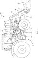
- FIG. 1 an agricultural vehicle in the form of a tractor 10 (carrier vehicle) is shown.
- the tractor 10 has an attached front loader assembly 12.
- the front loader assembly 12 includes a front loader 13, and on both sides of the tractor 10 attached to a vehicle frame 14 of the tractor 12 mounting frame 16 for coupling the front loader 13.
- the front loader 13 also has a boom on both sides of the tractor 18 on, by means of which the front loader 13 is coupled to the mounting frame 16 of the front loader assembly 12 and thus to the tractor 10.
- the front loader assembly 12 and the front loader 13 has a front loader rocker 20, which is pivotally attached to the attachment keys 18 and is adjoined by a pivotable front loader tool 22.
- the front loader rocker 20 extends on both sides of the tractor and comprises on both sides of the tractor 10 parallel support 21, which are interconnected via one or more cross members (not shown).
- the front loader tool 22 is designed, for example, in the form of a loading shovel, wherein the front loader tool 22 could also be designed as a loading fork, gripper, etc.
- the front loader swing arm 20 is connected via hydraulic lifting cylinders 24, which extend on both sides of the tractor 10 between the respective application keys 18 and the front loader rocker 20, pivotable.
- the front loader tool 22 is pivotable on both sides of the front loader rocker 20 via a pivot linkage 27 connected to the front loader rocker 20 and the front loader tool 22, and via a hydraulic swivel cylinder 28 connected to the respective pivot linkage 27 and the respective link 25.
- the attachment frame 16 has a receiving region 32 for receiving or coupling the add-on branch 18 and a fastening region 34 for attaching the attachment frame 16 to the vehicle frame 14. At the mounting portion 34 of the mounting frame 16 is screwed via screw (not shown) to the vehicle frame 14.
- the attachment frame 16 has a first catch hook 36 at a lower region of the receiving region 32 and a second catch hook 38 or respectively hook-shaped bearing points at an upper region of the receiving region 32.
- FIGS. 2 to 8 is a respective combination of add-on boom 18 and mounting frame 16 of the front loader assembly 12 shown enlarged in several side views and in several cross-sectional views, are shown in more detail the front loader assembly 12 in detail.
- the mounting frame 16 has a ramp 40 or ramp-shaped configuration which extends between the two catch hooks 36, 38 and in the lower region, starting from the upper Fanghaken 38 along the ramp 40, immediately before the lower fishing hook 36 has a recess 42 or notch.
- the attachment boom 18 comprises an upper and lower bearing in the form of an upper bearing pin 44 and a lower bearing pin 46. It is conceivable that the combination of fishing hooks 36, 38 and bearing pins 44, 46 can also be executed in the reverse manner, so that the Bearing bolts 44, 46 on the mounting frame 16 and the fishing hooks 36, 38 are formed on the mounting post 18.
- an upper, a middle and a lower pivot pin 48, 50, 52 are further arranged, which connect the steering linkage 26, the front loader rocker 20, and the hydraulic cylinder 24 each pivotally connected to the cultivation boom 18.
- the attachment post 18 further includes a pivot bar 54 which has a first pivot arm 56 and a second pivot arm 58 and is pivotally mounted about a pivot axis 60 (see also FIG. 9 ).
- a pivot bar 54 which has a first pivot arm 56 and a second pivot arm 58 and is pivotally mounted about a pivot axis 60 (see also FIG FIG. 9 ).
- an adjusting means in the form of a support means 62 is arranged, which is formed in the form of a support hinge.
- the support means 62 is hinged at the end of the first pivot arm 56 by means of a hinge 63 and biased by a coil spring 64 so that it is pressed or urged against the end of the first pivot arm 56 and in an extreme position at the end of the pivot arm 56 and . comes to rest on an end face 66 formed there.
- the underside of the first pivot arm 56 that is, the ramp 40 facing side of the pivot arm 56, has a shoulder 68 which is complementary to the formed on the ramp 40 recess 42 is formed.
- the second pivot arm 58 of the pivot bolt 54 is shorter and above the first pivot arm 56, at an angle of about 70 °, arranged (in the counterclockwise direction in the figures) and forms next to the first pivot arm 56 a further lever arm about the pivot axis 60th of the pivoting bolt 54.
- the second pivoting arm 58 is connected via a tension spring 70 to a frame part 72 of the attachment rode 18, so that a bias of the pivoting bolt 54 is generated in the direction of the ramp 40.
- an actuating element 74 is arranged (see FIG. 10 ), via which the pivot bolt 54 can be actuated.
- the actuating element 74 has an actuating lever 76 which is accessible on the outside of the add-on branch 18 and extends radially from a shaft 78.
- the shaft 78 is rotatably supported on the Anabaumast 18 between the two pivoting arms 56, 58.
- an actuating arm 80 is formed, which extends radially from the shaft 78 and is designed and arranged such that it can be brought into engagement by levering the shaft 78 with the second pivot arm 58 of the pivoting bolt 54 and levering it out or can put in a pivoting movement.
- the shaft is thereby rotated by pivoting the actuating lever 76 from a basic position ( FIGS. 2 to 5 . 7 and 8 ) in an engaged position (corresponding FIG. 6 ) is rotated, whereupon the actuating arm 80 is also pivoted and brought into engagement with the upper pivot arm 58 and thus with the pivot bolt 54 and the pivot bolt 54 from a locking position (see FIG. 5 ) in an unlocked position (see FIG. 6 ) can be moved. By pivoting back the pivot arm 58 and thus also the pivot bolt 54 is released again.
- a coupling or uncoupling of the front loader 13 or the add-on load 18 from the mounting frame 16 is as follows on the basis of FIGS. 2 to 8 described.
- the mounting frame 16 is moved from a disconnected state, in which the front loader 13 and hydraulically and mechanically separated from the tractor, according to the movement indicated by the arrow V in the direction of the attachment load 18 moves ( FIG. 2 ).
- the upper bearing pin 44 begins to engage the ramp 40 and slides up the inclined plane of the ramp 40 or along the ramp surface until it engages the upper catch hook 38 (FIG. Figures 3 and 4 ).
- the lower bearing pin 46 engages with the lower catch hook 36 ( Figures 3 and 4 ).
- the bearing pins 44, 46 engage the catch hooks 38, 36 ( FIG.
- FIGS. 6 to 8 show the unlocking of the front loader, ie the uncoupling of the add-on branch 18 from the mounting frame 16.
- the pivot bolt 54 is thereby brought by means of the actuating element 74 as described above from its locking position into an unlocked position ( FIG. 6 ).
- the spring-biased support means 62 assume its support position and the pivot bolt 54 are released from the actuator 74 again by the actuating lever is returned to its normal position.
- the pivot bolt 54 is now held by the support means 62 in the unlocked position.
- the mounting post 18 is unlocked in this state from the mounting frame 16, so that the mounting frame 18 can be removed from the mounting post 18, as indicated by the arrow R in the FIGS. 7 and 8th is indicated.
- the support means 62 is urged against the end face 66 of the pivot arm 56, whereby it maintains its support position and the pivot bolt 54 can not snap back into the recess ( FIG. 7 ).
- the attachment frame 16 By moving the attachment frame 16, ie by resetting the tractor 10, the attachment frame 16 can now be removed from the attachment boom 18, ie from the front loader 13, so that the uncoupling of the attachment boom 18 from the attachment frame 16 is completed ( FIG. 8 ). So that the front loader 13 can be completely separated and removed from the tractor 10, the hydraulic supply of the lifting cylinder 24 must be disconnected beforehand become. This can be done by the operator parallel to unlocking the pivot bolt 54, ie in a workflow, the pivot bolt 54 are unlocked and disconnected the hydraulic supply.
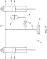
- the attachment boom 18 can adapt as freely as possible when coupling the position of the attachment frame 16, so that the bearing pins 44, 46 are guided as precisely and precisely as possible into the catch hooks. This is achieved in that the rigid connection between add-on boom 18 and loader rocker 20, in which the lift cylinders remain in their last occupied position with the hydraulic supply disconnected and hold the attachment boom 18 rigidly to the loader rocker 20, is canceled. The attachment boom 18 is thereby moved to a movable state in which it is pivotable relative to the loader rocker 20. This is how the Figures 11 and 12 schematically show a shut-off valve 82 and a hydraulic accumulator 84 is provided, wherein in FIG.
- FIG. 11 a hydraulic circuit for a single-acting and in FIG. 12 a hydraulic circuit for a double-acting lifting cylinder is shown.
- the check valve 82 is formed manually operable and can be operated by an operator when coupling and uncoupling of the front loader 13 when the hydraulic supply is connected or disconnected.
- FIG. 11 is a part of a hydraulic system 85 for the hydraulic supply of two unidirectional lifting cylinders 24 shown having a piston 86 and are hydraulically powered via a hydraulic supply line 87, wherein the supply line 87 of a Clutch part 88 of a hydraulic quick coupler (not shown) to piston bottom side chambers 90 of the lifting cylinder 24 extends.
- the lifting cylinder 24 piston bottom side are connected to the loader arm 20 and piston rod side with the boom 18, so that 90 can be raised by hydraulic filling of the piston bottom side chambers 90, the loader.
- a lowering of the loader rocker 20 takes place due to gravity, with a corresponding control of a control valve (not shown) of the hydraulic system 85 for raising and lowering the front loader takes place and by the weight of the front loader, the hydraulic oil from the piston bottom side chambers 90 can be pressed.
- the two lifting cylinders 24 are further connected by a connecting line 92 with each other and with the supply line 87, so both lifting cylinders 24 are equally pressurized.
- the shut-off valve 82 is arranged in a connecting line 94, which connects the supply line 87 with the hydraulic accumulator 84.
- Opening the shut-off valve 82 ensures that when the hydraulic supply is disconnected, the hydraulic fluid is not trapped in the piston-bottom side chambers 90 but can escape into the hydraulic accumulator 84, and vice versa.
- the lifting cylinders 24 can assume a floating position, in which the pistons 86 are freely movable. This state, in turn, allows a relatively free movement of the attachment boom 18 relative to the loader rocker 20, so that the attachment boom 18 can be aligned freely pivotable when coupling open when the shut-off valve 82 is open.
- the opening of the shut-off valve 82 is already ideally when disconnecting the front loader 13 and can in a workflow with unlocking the pivot bolt 54 and the disconnection of the hydraulic supply (disconnecting the Schnellkopplers) by an operator to be made. Because the shut-off valve 82 is already opened when the front loader 13 is uncoupled, it is already prepared for the next coupling process, so that an operator can leave the front loader 13 with freely movable attachment boom 18 without leaving the tractor 10. After coupling the front loader 13, the shut-off valve must be closed during start-up of the hydraulic function (connection of the hydraulic supply) to ensure hydraulic operation of the front loader 13. This can also be done in a workflow with the connection of the quick coupler.
- Fig. 1 shows a part of a hydraulic system 85 for the hydraulic supply of two double-acting lifting cylinders 24, which have a piston 86 and are hydraulically supplied via a hydraulic supply line 87 and a hydraulic supply line 95.
- the supply line 87 extends from a coupling part 88 of a hydraulic quick coupler (not shown) to piston crown side chambers 90 of the lift cylinders 24, the supply line 95 extending from the coupling part 88 to piston rod side chambers 96.
- the lifting cylinder 24 are piston bottom side connected to the loader rocker 20 and piston rod side with the boom 18, so that lifted by hydraulic filling of the piston bottom chambers 90, the loader rocker 20 and lowered, in a known manner, a corresponding control of a control valve (not shown) hydraulic system 85 for raising and lowering the front loader takes place.
- the two lifting cylinders 24 are piston bottom side connected by a connecting line 92 to each other and to the supply line 87. Furthermore, the lifting cylinders 24 piston rod side by a connecting line 98 with each other and connected to the supply line 95. Both hydraulic cylinders 24 are thereby equally pressurized.
- the hydraulic accumulator 84 is connected via a connecting line 100 to the supply line 95 and thus also to the connecting line 98 and the piston rod side chambers 96.
- the shut-off valve 82 is arranged in a connecting line 94, which connects the supply line 87 with the supply line 100. Opening the shut-off valve 82 ensures that when the hydraulic supply is disconnected, the hydraulic fluid is not trapped in the chambers 90, 96 but can escape into the hydraulic accumulator 84 and into the respective other chamber 90, 96, and vice versa.
- the lifting cylinders 24 can assume a floating position, in which the pistons 86 are freely movable, volume differences between the piston bottom side chambers 90 and the piston rod side chambers 96 being compensated by the hydraulic accumulator 84.
- This state allows a relatively free movement of the attachment boom 18 relative to the loader rocker 20, so that the attachment boom 18 can be aligned freely pivotable when coupling open when the shut-off valve 82 is open.
- the opening of the shut-off valve 82 when uncoupling the front loader 13 can be carried out in a workflow with an unlocking of the pivot bolt 54 and the disconnection of the hydraulic supply (disconnecting the quick coupler) by an operator.
- the shut-off valve are closed to ensure a hydraulic operation of the front loader 13.
- this can also be done in a workflow with the connection of the quick coupler.
Landscapes
- Engineering & Computer Science (AREA)
- Mechanical Engineering (AREA)
- General Engineering & Computer Science (AREA)
- Civil Engineering (AREA)
- Mining & Mineral Resources (AREA)
- Structural Engineering (AREA)
- Life Sciences & Earth Sciences (AREA)
- Soil Sciences (AREA)
- Environmental Sciences (AREA)
- Fluid Mechanics (AREA)
- Physics & Mathematics (AREA)
- Lifting Devices For Agricultural Implements (AREA)
- Agricultural Machines (AREA)
- Shovels (AREA)
Claims (4)
- Agencement à chargeur frontal (12) avec un cadre rapporté (16) et un mât rapporté (18), le mât rapporté (18) pouvant être couplé au cadre rapporté (16) et être découplé de lui, une coulisse de chargeur (20) reliée au mât rapporté (18) et pouvant pivoter via un vérin hydraulique (24) s'étendant entre la coulisse de chargeur (20) et le mât rapporté (18), caractérisé en ce que des moyens de réglage sont prévus au niveau de l'agencement à chargeur frontal (12) à travers lesquels le vérin hydraulique (24) peut être amené dans une position flottante lorsque l'alimentation hydraulique est découplée.
- Agencement à chargeur frontal (12) selon la revendication 1, caractérisé en ce que les moyens de réglage comprennent un accumulateur hydraulique (84) et une soupape de déblocage (82) via laquelle le vérin hydraulique (24) doté d'une chambre (90) située du côté de fond de piston peut être relié de façon hydraulique à l'accumulateur hydraulique (84).
- Agencement à chargeur frontal (12) selon la revendication 1 ou 2, caractérisé en ce que le vérin hydraulique (24) est réalisé avec une double action avec une chambre (90, 96) située du côté de tige de piston et située du côté de fond de piston, la soupape de déblocage (82) étant disposée entre les deux chambres (90, 96) et l'accumulateur hydraulique (84) prévu entre la soupape de déblocage (82) et la chambre (96) située du côté de tige de piston.
- Véhicule agricole (10) doté d'un agencement à chargeur frontal (12) selon l'une quelconque des revendications 1 à 3.
Applications Claiming Priority (1)
| Application Number | Priority Date | Filing Date | Title |
|---|---|---|---|
| DE102013219936 | 2013-10-01 |
Publications (2)
| Publication Number | Publication Date |
|---|---|
| EP2857593A1 EP2857593A1 (fr) | 2015-04-08 |
| EP2857593B1 true EP2857593B1 (fr) | 2016-12-28 |
Family
ID=51494189
Family Applications (1)
| Application Number | Title | Priority Date | Filing Date |
|---|---|---|---|
| EP14184211.2A Active EP2857593B1 (fr) | 2013-10-01 | 2014-09-10 | Système de chargeur frontal |
Country Status (3)
| Country | Link |
|---|---|
| US (1) | US9226439B2 (fr) |
| EP (1) | EP2857593B1 (fr) |
| CN (1) | CN104514236A (fr) |
Families Citing this family (6)
| Publication number | Priority date | Publication date | Assignee | Title |
|---|---|---|---|---|
| US10119242B1 (en) | 2018-03-27 | 2018-11-06 | Deere & Company | Front loader mounting arrangement for a work vehicle |
| US10982693B2 (en) * | 2018-04-10 | 2021-04-20 | Deere & Company | Automatically actuated shunt valve system |
| US10570581B2 (en) | 2018-06-01 | 2020-02-25 | Deere & Company | Latching arrangement for coupling a front loader to a work vehicle |
| US10676893B1 (en) * | 2019-09-10 | 2020-06-09 | Larry Irby Williams | Self-leveling front-end loader having a double boom with a dogleg bend of 105 to 135 degrees including an extension powered by hydraulic cylinders |
| US12398529B2 (en) | 2022-10-20 | 2025-08-26 | Deere & Company | Loader latching assist method and apparatus |
| USD1026968S1 (en) * | 2022-11-04 | 2024-05-14 | Deere & Company | Loader carrier for implements |
Family Cites Families (19)
| Publication number | Priority date | Publication date | Assignee | Title |
|---|---|---|---|---|
| US2946144A (en) * | 1957-05-28 | 1960-07-26 | Allis Chalmers Mfg Co | Hydraulic control system |
| US2936039A (en) * | 1959-03-23 | 1960-05-10 | Allis Chalmers Mfg Co | Vehicle steering and control apparatus |
| DE1294895B (de) * | 1961-08-31 | 1969-05-08 | Cordes | Gleiskettenfahrzeug mit einem zwischen den Gleisketten angeordneten Schuerfkuebel |
| NL7600034A (en) * | 1976-01-05 | 1977-07-07 | Hengstler Hydraulik | Hydraulic control for tractor:drawn swivel plough - has accumulator, valve to hydraulic pump, and valve bypassing swivel actuator piston |
| DK240490A (da) * | 1990-10-04 | 1992-04-05 | Thrige Agro As | Til- og afkoblingssystem for traktorredskaber saasom frontlaessere |
| GB2338470B (en) * | 1998-06-18 | 2002-03-20 | Agco Gmbh & Co | Detachable front loader |
| US6386821B1 (en) * | 1999-12-16 | 2002-05-14 | Bush Hog, L.L.C. | Mounting system for mid-mount front end loaders |
| SE524812C2 (sv) * | 2003-02-14 | 2004-10-05 | Hultdin System Ab | Dämpningsanordning hos ett hydraulsystem hos en arbetsmaskin och hydraulsystem innefattande en dämpningsanordning |
| SE525738C2 (sv) | 2003-09-09 | 2005-04-19 | Aaloe Ab | Anordning för montering av en lastare till ett fordon |
| US6986634B2 (en) * | 2003-11-21 | 2006-01-17 | Westendorf Manufacturing Co., Inc. | Loader/attachment assembly, method for using a loader/attachment assembly, and combination motor vehicle and loader/attachment assembly |
| FR2871485B1 (fr) | 2004-06-10 | 2006-09-01 | Etude Et D Innovation Dans Le | Dispositif d'accouplement d'un chargeur sur un tracteur |
| DE102006003768A1 (de) * | 2006-01-25 | 2007-07-26 | Wilhelm Stoll Maschinenfabrik Gmbh | Frontlader und Traktorkabine für einen Traktor |
| US9932721B2 (en) * | 2007-11-21 | 2018-04-03 | Volvo Construction Equipment Ab | System, working machine comprising the system, and method of springing an implement of a working machine during transport |
| FR2937827B1 (fr) * | 2008-10-30 | 2013-02-15 | Hubert Defrancq | Dispositif de relevage avant pour tracteur. |
| DE102009016571A1 (de) * | 2009-04-06 | 2010-10-07 | Agco Gmbh | Hydraulische Steueranordnung |
| JP5143858B2 (ja) * | 2010-04-20 | 2013-02-13 | 住友重機械工業株式会社 | 建設機械 |
| DE102010043135A1 (de) * | 2010-10-29 | 2012-05-03 | Deere & Company | Hydraulische Anordnung |
| DE102013222165A1 (de) * | 2013-10-01 | 2015-04-02 | Deere & Company | Frontladeranordnung |
| EP2857594B1 (fr) * | 2013-10-01 | 2016-12-28 | Deere & Company | Système de chargeur frontal avec un mechanism de verrouillage |
-
2014
- 2014-09-01 CN CN201410440876.8A patent/CN104514236A/zh active Pending
- 2014-09-10 EP EP14184211.2A patent/EP2857593B1/fr active Active
- 2014-09-30 US US14/501,203 patent/US9226439B2/en active Active
Non-Patent Citations (1)
| Title |
|---|
| None * |
Also Published As
| Publication number | Publication date |
|---|---|
| US9226439B2 (en) | 2016-01-05 |
| US20150093226A1 (en) | 2015-04-02 |
| EP2857593A1 (fr) | 2015-04-08 |
| CN104514236A (zh) | 2015-04-15 |
Similar Documents
| Publication | Publication Date | Title |
|---|---|---|
| EP2857594B1 (fr) | Système de chargeur frontal avec un mechanism de verrouillage | |
| EP2857592B1 (fr) | Circuit hydraulique pour le système de chargeur frontal d'un vehicule | |
| EP1239087B1 (fr) | Attache rapide | |
| EP1624116B1 (fr) | Attache rapide hydraulique | |
| EP2857593A1 (fr) | Système de chargeur frontal | |
| DE69120320T2 (de) | Erdbewegungsmaschine | |
| EP1362956B1 (fr) | Dispositif pour verrouiller un outil sur un bras élévateur | |
| EP0182091B1 (fr) | Elévateur de puissance pour un dispositif de levage | |
| DE102009046213B4 (de) | Wechselrahmen für einen Frontlader | |
| DE10159417C2 (de) | Schnellkupplung | |
| EP1813730A2 (fr) | Chargeur frontal et cabine pour tracteur | |
| DE102018206628A1 (de) | Dreipunkt-Kraftheber für einen landwirtschaftlichen Traktor | |
| DE4412115A1 (de) | Vorrichtung zum Anschluß einer Ausrüstung an eine Maschine, insbesondere eines Erntevorsatzes an eine Erntemaschine | |
| EP1008284A2 (fr) | Accouplement télescopique d'outil pour véhicule motorisé | |
| EP2829662B1 (fr) | Système de chargeur frontal | |
| EP1362957B1 (fr) | Dispositif pour verrouiller un outil sur an bras élévateur | |
| EP2412876B1 (fr) | Agencement de chargeur frontal | |
| EP0978592B1 (fr) | Chargeur et véhicule comprenant un chargeur | |
| EP3159452A1 (fr) | Chargeur frontal | |
| EP1389250A1 (fr) | Excavatrice sur roues | |
| DE102022109553B4 (de) | Fahrzeugkran mit einem Teleskopausleger mit einer Sicherungs- und Verriegelungseinheit | |
| EP2433483B1 (fr) | Dispositif de sécurité pour appareils de montage issus de la technique agricole | |
| DE10354957A1 (de) | Hydraulische Steueranordnung für ein mobiles Arbeitsgerät | |
| DE202009000858U1 (de) | Landmaschine | |
| CH713758A1 (de) | Schnellwechselkupplung zum Befestigen eines Anbaugeräts an einer Baumaschine, vorzugsweise an einem Baggerarm. |
Legal Events
| Date | Code | Title | Description |
|---|---|---|---|
| PUAI | Public reference made under article 153(3) epc to a published international application that has entered the european phase |
Free format text: ORIGINAL CODE: 0009012 |
|
| 17P | Request for examination filed |
Effective date: 20140910 |
|
| AK | Designated contracting states |
Kind code of ref document: A1 Designated state(s): AL AT BE BG CH CY CZ DE DK EE ES FI FR GB GR HR HU IE IS IT LI LT LU LV MC MK MT NL NO PL PT RO RS SE SI SK SM TR |
|
| AX | Request for extension of the european patent |
Extension state: BA ME |
|
| R17P | Request for examination filed (corrected) |
Effective date: 20151008 |
|
| RBV | Designated contracting states (corrected) |
Designated state(s): AL AT BE BG CH CY CZ DE DK EE ES FI FR GB GR HR HU IE IS IT LI LT LU LV MC MK MT NL NO PL PT RO RS SE SI SK SM TR |
|
| REG | Reference to a national code |
Ref country code: DE Ref legal event code: R079 Ref document number: 502014002315 Country of ref document: DE Free format text: PREVIOUS MAIN CLASS: E02F0003627000 Ipc: A01B0063108000 |
|
| GRAP | Despatch of communication of intention to grant a patent |
Free format text: ORIGINAL CODE: EPIDOSNIGR1 |
|
| RIC1 | Information provided on ipc code assigned before grant |
Ipc: A01B 63/10 20060101ALI20160615BHEP Ipc: E02F 9/22 20060101ALI20160615BHEP Ipc: A01B 63/108 20060101AFI20160615BHEP Ipc: F15B 1/02 20060101ALI20160615BHEP Ipc: B62D 49/06 20060101ALI20160615BHEP Ipc: E02F 3/43 20060101ALI20160615BHEP Ipc: E02F 3/627 20060101ALI20160615BHEP Ipc: E02F 3/36 20060101ALI20160615BHEP |
|
| INTG | Intention to grant announced |
Effective date: 20160718 |
|
| GRAS | Grant fee paid |
Free format text: ORIGINAL CODE: EPIDOSNIGR3 |
|
| GRAA | (expected) grant |
Free format text: ORIGINAL CODE: 0009210 |
|
| AK | Designated contracting states |
Kind code of ref document: B1 Designated state(s): AL AT BE BG CH CY CZ DE DK EE ES FI FR GB GR HR HU IE IS IT LI LT LU LV MC MK MT NL NO PL PT RO RS SE SI SK SM TR |
|
| REG | Reference to a national code |
Ref country code: GB Ref legal event code: FG4D Free format text: NOT ENGLISH |
|
| REG | Reference to a national code |
Ref country code: CH Ref legal event code: EP |
|
| REG | Reference to a national code |
Ref country code: AT Ref legal event code: REF Ref document number: 856492 Country of ref document: AT Kind code of ref document: T Effective date: 20170115 |
|
| REG | Reference to a national code |
Ref country code: IE Ref legal event code: FG4D Free format text: LANGUAGE OF EP DOCUMENT: GERMAN |
|
| REG | Reference to a national code |
Ref country code: DE Ref legal event code: R096 Ref document number: 502014002315 Country of ref document: DE |
|
| PG25 | Lapsed in a contracting state [announced via postgrant information from national office to epo] |
Ref country code: LV Free format text: LAPSE BECAUSE OF FAILURE TO SUBMIT A TRANSLATION OF THE DESCRIPTION OR TO PAY THE FEE WITHIN THE PRESCRIBED TIME-LIMIT Effective date: 20161228 |
|
| REG | Reference to a national code |
Ref country code: LT Ref legal event code: MG4D |
|
| PG25 | Lapsed in a contracting state [announced via postgrant information from national office to epo] |
Ref country code: GR Free format text: LAPSE BECAUSE OF FAILURE TO SUBMIT A TRANSLATION OF THE DESCRIPTION OR TO PAY THE FEE WITHIN THE PRESCRIBED TIME-LIMIT Effective date: 20170329 Ref country code: SE Free format text: LAPSE BECAUSE OF FAILURE TO SUBMIT A TRANSLATION OF THE DESCRIPTION OR TO PAY THE FEE WITHIN THE PRESCRIBED TIME-LIMIT Effective date: 20161228 Ref country code: NO Free format text: LAPSE BECAUSE OF FAILURE TO SUBMIT A TRANSLATION OF THE DESCRIPTION OR TO PAY THE FEE WITHIN THE PRESCRIBED TIME-LIMIT Effective date: 20170328 Ref country code: LT Free format text: LAPSE BECAUSE OF FAILURE TO SUBMIT A TRANSLATION OF THE DESCRIPTION OR TO PAY THE FEE WITHIN THE PRESCRIBED TIME-LIMIT Effective date: 20161228 |
|
| REG | Reference to a national code |
Ref country code: NL Ref legal event code: MP Effective date: 20161228 |
|
| PG25 | Lapsed in a contracting state [announced via postgrant information from national office to epo] |
Ref country code: HR Free format text: LAPSE BECAUSE OF FAILURE TO SUBMIT A TRANSLATION OF THE DESCRIPTION OR TO PAY THE FEE WITHIN THE PRESCRIBED TIME-LIMIT Effective date: 20161228 Ref country code: FI Free format text: LAPSE BECAUSE OF FAILURE TO SUBMIT A TRANSLATION OF THE DESCRIPTION OR TO PAY THE FEE WITHIN THE PRESCRIBED TIME-LIMIT Effective date: 20161228 Ref country code: RS Free format text: LAPSE BECAUSE OF FAILURE TO SUBMIT A TRANSLATION OF THE DESCRIPTION OR TO PAY THE FEE WITHIN THE PRESCRIBED TIME-LIMIT Effective date: 20161228 |
|
| PG25 | Lapsed in a contracting state [announced via postgrant information from national office to epo] |
Ref country code: NL Free format text: LAPSE BECAUSE OF FAILURE TO SUBMIT A TRANSLATION OF THE DESCRIPTION OR TO PAY THE FEE WITHIN THE PRESCRIBED TIME-LIMIT Effective date: 20161228 |
|
| PG25 | Lapsed in a contracting state [announced via postgrant information from national office to epo] |
Ref country code: SK Free format text: LAPSE BECAUSE OF FAILURE TO SUBMIT A TRANSLATION OF THE DESCRIPTION OR TO PAY THE FEE WITHIN THE PRESCRIBED TIME-LIMIT Effective date: 20161228 Ref country code: EE Free format text: LAPSE BECAUSE OF FAILURE TO SUBMIT A TRANSLATION OF THE DESCRIPTION OR TO PAY THE FEE WITHIN THE PRESCRIBED TIME-LIMIT Effective date: 20161228 Ref country code: CZ Free format text: LAPSE BECAUSE OF FAILURE TO SUBMIT A TRANSLATION OF THE DESCRIPTION OR TO PAY THE FEE WITHIN THE PRESCRIBED TIME-LIMIT Effective date: 20161228 Ref country code: IS Free format text: LAPSE BECAUSE OF FAILURE TO SUBMIT A TRANSLATION OF THE DESCRIPTION OR TO PAY THE FEE WITHIN THE PRESCRIBED TIME-LIMIT Effective date: 20170428 Ref country code: RO Free format text: LAPSE BECAUSE OF FAILURE TO SUBMIT A TRANSLATION OF THE DESCRIPTION OR TO PAY THE FEE WITHIN THE PRESCRIBED TIME-LIMIT Effective date: 20161228 |
|
| PG25 | Lapsed in a contracting state [announced via postgrant information from national office to epo] |
Ref country code: PL Free format text: LAPSE BECAUSE OF FAILURE TO SUBMIT A TRANSLATION OF THE DESCRIPTION OR TO PAY THE FEE WITHIN THE PRESCRIBED TIME-LIMIT Effective date: 20161228 Ref country code: SM Free format text: LAPSE BECAUSE OF FAILURE TO SUBMIT A TRANSLATION OF THE DESCRIPTION OR TO PAY THE FEE WITHIN THE PRESCRIBED TIME-LIMIT Effective date: 20161228 Ref country code: PT Free format text: LAPSE BECAUSE OF FAILURE TO SUBMIT A TRANSLATION OF THE DESCRIPTION OR TO PAY THE FEE WITHIN THE PRESCRIBED TIME-LIMIT Effective date: 20170428 Ref country code: IT Free format text: LAPSE BECAUSE OF FAILURE TO SUBMIT A TRANSLATION OF THE DESCRIPTION OR TO PAY THE FEE WITHIN THE PRESCRIBED TIME-LIMIT Effective date: 20161228 Ref country code: BG Free format text: LAPSE BECAUSE OF FAILURE TO SUBMIT A TRANSLATION OF THE DESCRIPTION OR TO PAY THE FEE WITHIN THE PRESCRIBED TIME-LIMIT Effective date: 20170328 Ref country code: ES Free format text: LAPSE BECAUSE OF FAILURE TO SUBMIT A TRANSLATION OF THE DESCRIPTION OR TO PAY THE FEE WITHIN THE PRESCRIBED TIME-LIMIT Effective date: 20161228 |
|
| REG | Reference to a national code |
Ref country code: FR Ref legal event code: PLFP Year of fee payment: 4 |
|
| REG | Reference to a national code |
Ref country code: DE Ref legal event code: R097 Ref document number: 502014002315 Country of ref document: DE |
|
| PLBE | No opposition filed within time limit |
Free format text: ORIGINAL CODE: 0009261 |
|
| STAA | Information on the status of an ep patent application or granted ep patent |
Free format text: STATUS: NO OPPOSITION FILED WITHIN TIME LIMIT |
|
| PG25 | Lapsed in a contracting state [announced via postgrant information from national office to epo] |
Ref country code: DK Free format text: LAPSE BECAUSE OF FAILURE TO SUBMIT A TRANSLATION OF THE DESCRIPTION OR TO PAY THE FEE WITHIN THE PRESCRIBED TIME-LIMIT Effective date: 20161228 |
|
| 26N | No opposition filed |
Effective date: 20170929 |
|
| PG25 | Lapsed in a contracting state [announced via postgrant information from national office to epo] |
Ref country code: SI Free format text: LAPSE BECAUSE OF FAILURE TO SUBMIT A TRANSLATION OF THE DESCRIPTION OR TO PAY THE FEE WITHIN THE PRESCRIBED TIME-LIMIT Effective date: 20161228 |
|
| REG | Reference to a national code |
Ref country code: CH Ref legal event code: PL |
|
| PG25 | Lapsed in a contracting state [announced via postgrant information from national office to epo] |
Ref country code: MC Free format text: LAPSE BECAUSE OF FAILURE TO SUBMIT A TRANSLATION OF THE DESCRIPTION OR TO PAY THE FEE WITHIN THE PRESCRIBED TIME-LIMIT Effective date: 20161228 |
|
| REG | Reference to a national code |
Ref country code: IE Ref legal event code: MM4A |
|
| REG | Reference to a national code |
Ref country code: BE Ref legal event code: MM Effective date: 20170930 |
|
| PG25 | Lapsed in a contracting state [announced via postgrant information from national office to epo] |
Ref country code: LU Free format text: LAPSE BECAUSE OF NON-PAYMENT OF DUE FEES Effective date: 20170910 |
|
| PG25 | Lapsed in a contracting state [announced via postgrant information from national office to epo] |
Ref country code: IE Free format text: LAPSE BECAUSE OF NON-PAYMENT OF DUE FEES Effective date: 20170910 Ref country code: CH Free format text: LAPSE BECAUSE OF NON-PAYMENT OF DUE FEES Effective date: 20170930 Ref country code: LI Free format text: LAPSE BECAUSE OF NON-PAYMENT OF DUE FEES Effective date: 20170930 |
|
| PG25 | Lapsed in a contracting state [announced via postgrant information from national office to epo] |
Ref country code: BE Free format text: LAPSE BECAUSE OF NON-PAYMENT OF DUE FEES Effective date: 20170930 |
|
| REG | Reference to a national code |
Ref country code: FR Ref legal event code: PLFP Year of fee payment: 5 |
|
| PG25 | Lapsed in a contracting state [announced via postgrant information from national office to epo] |
Ref country code: MT Free format text: LAPSE BECAUSE OF FAILURE TO SUBMIT A TRANSLATION OF THE DESCRIPTION OR TO PAY THE FEE WITHIN THE PRESCRIBED TIME-LIMIT Effective date: 20161228 |
|
| PG25 | Lapsed in a contracting state [announced via postgrant information from national office to epo] |
Ref country code: HU Free format text: LAPSE BECAUSE OF FAILURE TO SUBMIT A TRANSLATION OF THE DESCRIPTION OR TO PAY THE FEE WITHIN THE PRESCRIBED TIME-LIMIT; INVALID AB INITIO Effective date: 20140910 |
|
| PG25 | Lapsed in a contracting state [announced via postgrant information from national office to epo] |
Ref country code: CY Free format text: LAPSE BECAUSE OF FAILURE TO SUBMIT A TRANSLATION OF THE DESCRIPTION OR TO PAY THE FEE WITHIN THE PRESCRIBED TIME-LIMIT Effective date: 20161228 |
|
| PG25 | Lapsed in a contracting state [announced via postgrant information from national office to epo] |
Ref country code: MK Free format text: LAPSE BECAUSE OF FAILURE TO SUBMIT A TRANSLATION OF THE DESCRIPTION OR TO PAY THE FEE WITHIN THE PRESCRIBED TIME-LIMIT Effective date: 20161228 |
|
| PG25 | Lapsed in a contracting state [announced via postgrant information from national office to epo] |
Ref country code: TR Free format text: LAPSE BECAUSE OF FAILURE TO SUBMIT A TRANSLATION OF THE DESCRIPTION OR TO PAY THE FEE WITHIN THE PRESCRIBED TIME-LIMIT Effective date: 20161228 |
|
| PG25 | Lapsed in a contracting state [announced via postgrant information from national office to epo] |
Ref country code: AL Free format text: LAPSE BECAUSE OF FAILURE TO SUBMIT A TRANSLATION OF THE DESCRIPTION OR TO PAY THE FEE WITHIN THE PRESCRIBED TIME-LIMIT Effective date: 20161228 |
|
| REG | Reference to a national code |
Ref country code: AT Ref legal event code: MM01 Ref document number: 856492 Country of ref document: AT Kind code of ref document: T Effective date: 20190910 |
|
| PG25 | Lapsed in a contracting state [announced via postgrant information from national office to epo] |
Ref country code: AT Free format text: LAPSE BECAUSE OF NON-PAYMENT OF DUE FEES Effective date: 20190910 |
|
| PGFP | Annual fee paid to national office [announced via postgrant information from national office to epo] |
Ref country code: DE Payment date: 20240821 Year of fee payment: 11 |
|
| PGFP | Annual fee paid to national office [announced via postgrant information from national office to epo] |
Ref country code: GB Payment date: 20240927 Year of fee payment: 11 |
|
| PGFP | Annual fee paid to national office [announced via postgrant information from national office to epo] |
Ref country code: FR Payment date: 20240925 Year of fee payment: 11 |