EP2857597B1 - Machine de construction avec échelles et un couvercle pour un compartiment - Google Patents
Machine de construction avec échelles et un couvercle pour un compartiment Download PDFInfo
- Publication number
- EP2857597B1 EP2857597B1 EP13798155.1A EP13798155A EP2857597B1 EP 2857597 B1 EP2857597 B1 EP 2857597B1 EP 13798155 A EP13798155 A EP 13798155A EP 2857597 B1 EP2857597 B1 EP 2857597B1
- Authority
- EP
- European Patent Office
- Prior art keywords
- step member
- indentation
- flat plate
- compartment cover
- plate
- Prior art date
- Legal status (The legal status is an assumption and is not a legal conclusion. Google has not performed a legal analysis and makes no representation as to the accuracy of the status listed.)
- Active
Links
Images


Classifications
-
- E—FIXED CONSTRUCTIONS
- E02—HYDRAULIC ENGINEERING; FOUNDATIONS; SOIL SHIFTING
- E02F—DREDGING; SOIL-SHIFTING
- E02F9/00—Component parts of dredgers or soil-shifting machines, not restricted to one of the kinds covered by groups E02F3/00 - E02F7/00
- E02F9/08—Superstructures; Supports for superstructures
-
- E—FIXED CONSTRUCTIONS
- E02—HYDRAULIC ENGINEERING; FOUNDATIONS; SOIL SHIFTING
- E02F—DREDGING; SOIL-SHIFTING
- E02F9/00—Component parts of dredgers or soil-shifting machines, not restricted to one of the kinds covered by groups E02F3/00 - E02F7/00
- E02F9/16—Cabins, platforms, or the like, for drivers
-
- B—PERFORMING OPERATIONS; TRANSPORTING
- B60—VEHICLES IN GENERAL
- B60R—VEHICLES, VEHICLE FITTINGS, OR VEHICLE PARTS, NOT OTHERWISE PROVIDED FOR
- B60R3/00—Arrangements of steps or ladders facilitating access to or on the vehicle, e.g. running-boards
-
- B—PERFORMING OPERATIONS; TRANSPORTING
- B62—LAND VEHICLES FOR TRAVELLING OTHERWISE THAN ON RAILS
- B62D—MOTOR VEHICLES; TRAILERS
- B62D33/00—Superstructures for load-carrying vehicles
- B62D33/06—Drivers' cabs
- B62D33/0617—Drivers' cabs for tractors or off-the-road vehicles
-
- E—FIXED CONSTRUCTIONS
- E02—HYDRAULIC ENGINEERING; FOUNDATIONS; SOIL SHIFTING
- E02F—DREDGING; SOIL-SHIFTING
- E02F9/00—Component parts of dredgers or soil-shifting machines, not restricted to one of the kinds covered by groups E02F3/00 - E02F7/00
- E02F9/08—Superstructures; Supports for superstructures
- E02F9/0833—Improving access, e.g. for maintenance, steps for improving driver's access, handrails
-
- E—FIXED CONSTRUCTIONS
- E02—HYDRAULIC ENGINEERING; FOUNDATIONS; SOIL SHIFTING
- E02F—DREDGING; SOIL-SHIFTING
- E02F9/00—Component parts of dredgers or soil-shifting machines, not restricted to one of the kinds covered by groups E02F3/00 - E02F7/00
- E02F9/08—Superstructures; Supports for superstructures
- E02F9/0858—Arrangement of component parts installed on superstructures not otherwise provided for, e.g. electric components, fenders, air-conditioning units
- E02F9/0875—Arrangement of valve arrangements on superstructures
-
- E—FIXED CONSTRUCTIONS
- E02—HYDRAULIC ENGINEERING; FOUNDATIONS; SOIL SHIFTING
- E02F—DREDGING; SOIL-SHIFTING
- E02F9/00—Component parts of dredgers or soil-shifting machines, not restricted to one of the kinds covered by groups E02F3/00 - E02F7/00
- E02F9/08—Superstructures; Supports for superstructures
- E02F9/0858—Arrangement of component parts installed on superstructures not otherwise provided for, e.g. electric components, fenders, air-conditioning units
- E02F9/0891—Lids or bonnets or doors or details thereof
-
- E—FIXED CONSTRUCTIONS
- E02—HYDRAULIC ENGINEERING; FOUNDATIONS; SOIL SHIFTING
- E02F—DREDGING; SOIL-SHIFTING
- E02F9/00—Component parts of dredgers or soil-shifting machines, not restricted to one of the kinds covered by groups E02F3/00 - E02F7/00
- E02F9/26—Indicating devices
-
- Y—GENERAL TAGGING OF NEW TECHNOLOGICAL DEVELOPMENTS; GENERAL TAGGING OF CROSS-SECTIONAL TECHNOLOGIES SPANNING OVER SEVERAL SECTIONS OF THE IPC; TECHNICAL SUBJECTS COVERED BY FORMER USPC CROSS-REFERENCE ART COLLECTIONS [XRACs] AND DIGESTS
- Y02—TECHNOLOGIES OR APPLICATIONS FOR MITIGATION OR ADAPTATION AGAINST CLIMATE CHANGE
- Y02T—CLIMATE CHANGE MITIGATION TECHNOLOGIES RELATED TO TRANSPORTATION
- Y02T10/00—Road transport of goods or passengers
- Y02T10/60—Other road transportation technologies with climate change mitigation effect
- Y02T10/72—Electric energy management in electromobility
Definitions
- This invention relates to a construction machine, such as a hydraulic excavator, which is provided with steps and a compartment cover laterally to a seat.
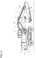
- FIG. 4 is a side view showing a wheeled excavator as a hydraulic excavator referred to as an example of a construction machine.
- the wheeled excavator shown in FIG. 4 is provided with a travel base 1, a upperstructure 2 mounted on the travel base 1, and working equipment 3 attached tiltably in an up-and-down direction to the upperstructure 2.
- a body is constituted by the travel base 1 and upperstructure 2.
- the working equipment 3 includes a boom 4 attached to the upperstructure 2, an arm 5 connected to a free end of the boom 4, and a bucket 6 attached to a free end of the arm 5.
- the working equipment 3 also includes boom cylinders 4a for driving the boom 4, an arm cylinder 5a for driving the arm 5, and a bucket cylinder 6a for driving the bucket 6.
- the upperstructure 2 is provided on a revolving frame 2a thereof with a cab 7 in which a seat is disposed, and is provided at a rear position thereof with a counterweight 8 that ensures weight balance.
- the above-mentioned working equipment 3 is arranged laterally to, specifically on a right side of the cab 7.
- steps 11 are arranged including plural step members that allow an operator to ascend to or descend from the upperstructure 2 by stepping on them.
- a compartment cover 9 is arranged on a right side of the steps 11.
- control valves that control actuators for example, the boom cylinders 4a, the arm cylinder 5a and the like are disposed in an accommodation space formed, for example, by the steps 11 and compartment cover 9.
- Patent Document 1 As a conventional technology of this sort, there is one disclosed in Patent Document 1.
- Patent Document 1 JP-A-2010-106450
- US 3 997 183 A relates to a step-grab element system for a vehicle being provided for ascending to or descending from an elevated position on a vehicle.
- a step and a grab element are each pivotally connected to the vehicle and are connected to one another for moving the step between an operable position and an inoperable, protected position in response to moving the grab element between an operable position and an inoperable, protected position.
- JP 2008 111253 A relates to a mount of a working lamp while securing storage space for mounting devices in a right front cover.
- the working lamp is disposed outside the right front cover containing the mounting devices such as a control valve group and a hydraulic hose/pipe group.
- WO 2007/062464 A1 relates to an access device for earthmoving equipment to allow a person to move from ground level to an elevated position.
- the present invention has as an object thereof the provision of a construction machine that can realize the assurance of good vision for an operator sitting in a seat.
- the present invention relates to a construction machine provided with a body, working equipment attached to the body, a seat disposed on the body, steps arranged laterally to the seat and comprising plural step members, and a compartment cover arranged on a side opposite to the seat with respect to the steps, an indentation is formed in the compartment cover at a part thereof that faces a space defined between the plural step members.
- an operator sitting in the seat can see out of the compartment cover through the space, which is defined between the step members, and the indentation in the compartment cover, said indentation corresponding to the space .
- the present invention can, therefore, realize the assurance of good vision for the operator sitting in the seat.
- the indentation has been formed upon press working to fabricate the compartment cover, and comprises an arcuate indentation as seen in a side view. According to the present invention configured as described above, the indentation is also formed upon press working to fabricate the compartment cover, thereby making it possible to decrease the man-hour needed for the formation of the indentation.
- the steps further comprise plates on which the plural step members are secured, the plural step members comprise an upper step member arranged at an upper position, and a lower step member arranged at a position immediately below the upper step member, and the indentation is located at an upper extremity thereof in a neighborhood of a lower surface of the upper step member and at an lower extremity thereof in a neighborhood of an upper surface of the lower step member, and as seen in a side view, is formed such that a most indented portion thereof is as proximate as possible to the associated one of the plates.
- the present invention configured as described above can assure, by the indentation, the formation of a large open space in the compartment cover, and therefore, can realize the assurance of better vision for the operator sitting in the seat.
- a plurality of indentations as defined above are formed along a direction to arrangement of the steps.
- the present invention configured as described above can assure, for the operator sitting in the seat, a wide range of vision along the direction to arrangement of the steps, and therefore, can realize the assurance of still better vision for the operator sitting in the seat.
- the construction machine has a cab, in which the seat is disposed, on a left side of the body, the working equipment on a right side of the cab, the steps on a right side of the working equipment, and the compartment cover on a right side of the steps, all as viewed toward a front of the body, and control valves that control flows of hydraulic oil to actuators are disposed in an accommodation space formed by the steps and the compartment cover.
- the present invention configured as described above can realize the assurance of good, right side vision for the operator sitting in the seat inside the cab.
- the present invention can realize the conventionally-desired assurance of good vision for an operator sitting in a seat, and can provide a construction machine with work performance and work safety improved over those of conventional construction machines.
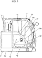
- FIG. 1 is a fragmentary side view showing the embodiment of the present invention
- FIG. 2 is a fragmentary perspective view depicting this embodiment
- FIG. 3 is an enlarged side view illustrating a relationship in layout between steps and indentations formed in a compartment cover, with all of which this embodiment is provided.
- the construction machine according to this embodiment is, for example, a wheeled excavator as a hydraulic excavator.
- the fundamental configuration of the wheeled excavator according to this embodiment is similar, for example, to the one mentioned above and shown in FIG. 4 . It is the matter associated with the compartment cover that this embodiment is different from the one shown in FIG. 4 . Therefore, a description will hereinafter be made by also using, as needed, the signs and terms employed in connection with the above-mentioned wheeled excavator shown in FIG. 4 .
- the wheeled excavator As described with reference to FIG. 4 , the wheeled excavator according to this embodiment is provided with the travel base 1 and upperstructure 2 that constitute a body, and on the revolving frame 2a, is also provided with the cab 7. On a right side of the cab 7, the working equipment 3 is arranged including the boom, the arm 5, and the like. It is to be noted that in FIG. 2 , the wheeled excavator is depicted with the working equipment 3 detached therefrom.
- the boom 4 is connected to a bracket 15 such that it is pivotable in an up-and-down direction, and the boom cylinders 4a are connected to brackets 16 such that they are pivotable in an up-and-down direction.
- the steps 11 are arranged on a right side of the working equipment 3 attached to the upperstructure 2 via the brackets 15,16, and the compartment cover 13 is arranged on a right side of the steps 11.
- the seat is disposed on a base 14 arranged in the cab 7.
- the steps 11 include plural step members, and plates on which these plural step members are secured. Described specifically, as shown in FIGS. 2 and 3 , the step members are provided, with a first plate 20 arranged on a lower side and a second plate 21 fixed on the first plate 20 by bolts, and also with a first step member 22, second step member 23 and third step member 24.
- the first plate 20 has a lower flat plate part 20a fixed on a member arranged on the revolving frame 2a, a vertical riser part 20b formed by bending from the lower flat plate part 20a, an inclined riser part 20c formed by bending from the vertical riser part 20b, and an upper flat plate part 20d formed by bending from the inclined riser part 20c.
- the second plate 21 has, a lower flat plate part 21a placed on the upper flat plate part 20d of the first plate 20 and fixed on the upper flat plate part 20d by bolts, an inclined riser part 21b formed by bending from the lower flat plate part 21a, and an upper flat plate part 21c formed by bending from the inclined riser part 21b and fixed on a member arranged on the revolving frame 2a.
- the first step member 22 is fixed on the lower flat plate part 20a of the first plate 20.
- the second step member 23 is fixed by welding on the inclined riser part 20c of the first plate 20 such that its upper wall 23a lies in flush with the lower flat plate part 21a of the second plate 21.
- the third step member 24 is fixed by welding on the inclined riser part 21b of the second plate 21 such that its upper wall 24a lies in flush with the upper flat plate part 21c of the second plate 21.
- the tread depth S1 of the first step member 22, the tread depth S2 including the upper wall 23a of the second step member 23 and the lower flat plate part 21a of the second plate 21, and the tread depth S3 including the upper wall 24a of the third step member 24 and the upper flat plate part 21c of the second plate 21, all of which are illustrated in FIG. 3 , are set at predetermined standard dimensions or greater, respectively.
- a space 25 is defined between the second step member 23 and the third step member 24, and in addition, a space 26 is defined between the first step member 22 and the second step member 23.
- control valves 12 and the like which control actuators such as the boom cylinders 4a and arm cylinder 5a, are disposed in an accommodation space formed by the steps 11 and the compartment cover 13.
- plural indentations are formed, along the direction to arrangement of the steps 11 in the compartment cover 13 at parts thereof that face the spaces 25,26, respectively. Described specifically, as shown in FIGS. 2 and 3 , an upper indentation 13a is formed in an edge part of the compartment cover 13 such that it faces the space 25, and a lower indentation 13b is formed in the edge part of the compartment cover 13 such that it faces the space 26.
- upper indentation 13a and lower indentation 13b are formed upon pressing work to fabricate the compartment cover 13, and as illustrated in FIG. 3 , comprise arcuate indentations, respectively, as seen in a side view.
- the upper indentation 13a is formed such that its upper extremity is located in a neighborhood of a lower surface 24b of the third step member 24 forming an upper step member arranged at an upper position relative to the second step member 23, its lower extremity is located in a neighborhood of an upper surface 23a of the second step member 23 forming a lower step member arranged at a position immediately below the third step member 24, and as seen in the side view illustrated in FIG. 3 , a most indented portion 13a1 of the upper indentation 13a is as proximate as possible to the inclined riser part 21b of the second plate 21 from the manufacturing standpoint.
- the above-mentioned “in a neighborhood of a lower surface 24b" of the third step member 24 includes a lower surface 24b and its adjacent portion or portions. It is also to be noted that the above-mentioned “in a neighborhood of an upper surface 23a" of the second step member 23 includes an upper wall 23a and its adjacent portion or portions.
- the lower indentation 13a is also formed such that its upper extremity is located in a neighborhood of a lower surface 23b of the second step member 23 forming an upper step member arranged at an upper position relative to the first step member 22, its lower extremity is located in a neighborhood of an upper surface 22a of the first step member 22 forming a lower step member arranged at a position immediately below the second step member 23, and as seen in the side view illustrated in FIG. 3 , a most indented portion 13b1 of the lower indentation 13b is as proximate as possible to the vertical riser part 20b of the first plate 20 from the manufacturing standpoint.
- the above-mentioned “in a neighborhood of lower surface 23b" of the second step member 23 includes a lower surface 23b and its adjacent portion or portions. It is also to be noted that the above-mentioned “in a neighborhood of upper surface 22a" of the first step member 22 includes the upper surface 22a and its adjacent portion or portions.
- This embodiment configured as described above allows an operator, who is sitting in the unillustrated seat disposed on the base 14 inside the cab 7 depicted in FIG. 2 , to see the right side of the compartment cover 13 through the space 25 defined between the second step member 23 and the third step member 24 and the upper indentation 13a formed in the compartment cover 13 in correspondence to the space 25, and also through the space 26 defined between the first step member 22 and the second step member 23 and the lower indentation 13b formed in the compartment cover 13 in correspondence to the space 26.
- This embodiment therefore, can realize the assurance of good right side vision for the operator sitting in the seat. As a consequence, this embodiment can provide the wheeled excavator with improved work performance and work safety.
- this embodiment can decrease the man-hour needed for the formation of the upper indentation 13a and lower indentation 13b, thereby making it possible to reduce an increase in manufacturing cost.
- This embodiment is provided with the upper indentation 13a formed to extend along the space 26 as much as possible from the manufacturing standpoint and the lower indentation 13b formed to extend along the space 26 as much as possible from the manufacturing standpoint. Therefore, this embodiment can assure, by the indentations, the formation of large open spaces in the compartment cover 13, and can realize the assurance of still better vision for the operator sitting in the seat.
- the plural indentations that is, the upper indentation 13a and lower indentation 13 bare formed in the compartment cover 13. Accordingly, this embodiment can assure, for the operator sitting in the seat, a wide range of vision along the direction to arrangement of the steps 11, and can realize the assurance of still better vision for the operator sitting in the seat.
- the present invention is not limited to wheeled excavators although the construction machine according to the above-described embodiment is configured as a wheeled excavator.
- the present invention can be applied to crawler hydraulic excavators .
- the present invention can also be applied even to construction machines different from hydraulic excavators provided that they are each provided with a compartment cover on a side opposite to a seat with respect to steps including plural step members and arranged laterally to the seat.
- the construction machine may be configured to form such indentations as substantially conforming to the steps as seen in a side view in place of such arcuate upper indentation 13a and lower indentation 13b as in this embodiment.
- the construction machine may be configured to form such indentations as substantially conforming to the steps as seen in a side view in place of such arcuate upper indentation 13a and lower indentation 13b as in this embodiment.
Landscapes
- Engineering & Computer Science (AREA)
- Mining & Mineral Resources (AREA)
- Civil Engineering (AREA)
- General Engineering & Computer Science (AREA)
- Structural Engineering (AREA)
- Mechanical Engineering (AREA)
- Chemical & Material Sciences (AREA)
- Combustion & Propulsion (AREA)
- Transportation (AREA)
- Component Parts Of Construction Machinery (AREA)
- Body Structure For Vehicles (AREA)
Claims (1)
- Machine de chantier comprenant :- un corps, dans lequel le corps est constitué d'une structure de base de déplacement (1) et d'une structure supérieure (2), dans laquelle la structure supérieure (2) a un châssis pivotant (2a) ;- un siège ;- une base (14) ;- une cabine (7), dans laquelle le siège est disposé sur la base (14) qui est agencée dans la cabine (7) ;- un équipement de travail (3) attaché au corps sur un côté droit de la cabine (7) ;- des marches (11) agencées sur un côté droit de l'équipement de travail (3) et incluant une pluralité d'éléments formant marches (22, 23, 24) et une pluralité de plaques (20, 21) sur lesquelles la pluralité d'éléments formant marches (22, 23, 24) sont attachées ; et- un couvercle de compartiment (13) agencé sur un côté droit des marches (11),
caractérisée en ce que
les plaques (20, 21) incluent :une première plaque (20) qui est dotée d'une partie de plaque plate inférieure (20a) fixée sur un élément disposé sur le châssis pivotant (2a), une partie de contremarche verticale (20b) formée par pliage à partir de la partie de plaque plate inférieure (20a), une partie de contremarche inclinée (20c) formée par pliage à partir de la partie de contremarche verticale (20b), et une partie de plaque plate supérieure (20d) formée par pliage à partir de la partie de contremarche inclinée (20c) ; etune deuxième plaque (21) qui est dotée d'une partie de plaque plate inférieure (21a) placée sur la partie de plaque plate supérieure (20d) de la première plaque (20) et qui est fixée sur la partie de plaque plate supérieure (20d) au moyen de boulons, une partie de contremarche inclinée (21b) formée par pliage à partir de la partie de plaque plate inférieure (21a), et une partie de plaque plate supérieure (21c) formée par pliage à partir de la partie de contremarche inclinée (21 b) et qui est fixée sur un élément disposé sur le châssis pivotant (2a),un premier élément formant marche (22) est fixé sur la partie de plaque plate inférieure (20a) de la première plaque (20),un deuxième élément formant marche (23) est fixé par soudage sur la partie de contremarche inclinée (20c) de la première plaque (20),un troisième élément formant marche (24) est fixé par soudage sur la partie de contremarche inclinée (21b) de la deuxième plaque (21),des espaces (25, 26) dans lesquels un premier espace (25) est prévu entre le deuxième élément formant marche (23) et le troisième élément formant marche (24), et un deuxième espace (26) est prévu entre le premier élément formant marche (22) et le deuxième élément formant marche (24),une entaille supérieure (13a) est réalisée dans une partie formant bord du couvercle de compartiment (13) au niveau d'une partie de celui-ci qui fait face au premier espace (25) entre le troisième élément formant marche (24) et le deuxième élément formant marche (23), et une entaille inférieure (13b) est réalisée dans la partie formant bord du couvercle de compartiment (13) au niveau d'une partie de celui-ci qui fait face au deuxième espace (26) entre le deuxième élément formant marche (23) et le premier élément formant marche (22),l'entaille supérieure (13a) et l'entaille inférieure (13b) ont été réalisées par un travail de pressage pour fabriquer le couvercle de compartiment (13), et comprennent respectivement une entaille arquée, observée dans une vue latérale,l'entaille supérieure (13a) est agencée de sorte que son extrémité supérieure est située de manière adjacente à une surface inférieure (24b) du troisième élément formant marche (24), réalisant un élément formant marche supérieur qui est agencé à une position supérieure relativement au deuxième élément formant marche (23), et de sorte que son extrémité inférieure est située de manière adjacente à une surface supérieure (23a) du deuxième élément formant marche (23), réalisant un élément formant marche inférieur qui est agencé à une position immédiatement en dessous du troisième élément formant marche (24), et, observée dans une vue latérale, une portion la plus entaillée (13a1) de l'entaille supérieure (13a) est aussi proche que possible de la partie de contremarche inclinée (21b) de la deuxième plaque (21), etl'entaille inférieure (13b) est agencée de sorte que son extrémité supérieure est située de manière adjacente à une surface inférieure (23b) du deuxième élément formant marche (23), réalisant un élément formant marche supérieur qui est agencé à une position supérieure relativement au premier élément formant marche (22), et de sorte que son extrémité inférieure est située de manière adjacente à une surface supérieure (22a) du premier élément formant marche (22), réalisant un élément formant marche inférieur qui est agencé à une position immédiatement en dessous du deuxième élément formant marche (23), et, observée dans une vue latérale, une portion la plus entaillée (13b1) de l'entaille inférieure (13b) est aussi proche que possible de la partie de contremarche verticale (20b) de la première plaque (20).
Applications Claiming Priority (2)
| Application Number | Priority Date | Filing Date | Title |
|---|---|---|---|
| JP2012121052A JP5824414B2 (ja) | 2012-05-28 | 2012-05-28 | 建設機械 |
| PCT/JP2013/059361 WO2013179755A1 (fr) | 2012-05-28 | 2013-03-28 | Machine de construction |
Publications (3)
| Publication Number | Publication Date |
|---|---|
| EP2857597A1 EP2857597A1 (fr) | 2015-04-08 |
| EP2857597A4 EP2857597A4 (fr) | 2016-09-07 |
| EP2857597B1 true EP2857597B1 (fr) | 2020-02-12 |
Family
ID=49672963
Family Applications (1)
| Application Number | Title | Priority Date | Filing Date |
|---|---|---|---|
| EP13798155.1A Active EP2857597B1 (fr) | 2012-05-28 | 2013-03-28 | Machine de construction avec échelles et un couvercle pour un compartiment |
Country Status (6)
| Country | Link |
|---|---|
| US (1) | US9309644B2 (fr) |
| EP (1) | EP2857597B1 (fr) |
| JP (1) | JP5824414B2 (fr) |
| KR (1) | KR101688499B1 (fr) |
| CN (1) | CN104334804B (fr) |
| WO (1) | WO2013179755A1 (fr) |
Families Citing this family (3)
| Publication number | Priority date | Publication date | Assignee | Title |
|---|---|---|---|---|
| CN104520514B (zh) * | 2013-08-08 | 2016-07-06 | 株式会社小松制作所 | 轮式装载机 |
| JP2021155972A (ja) * | 2020-03-26 | 2021-10-07 | 株式会社日立建機ティエラ | 建設機械 |
| USD936709S1 (en) * | 2020-05-15 | 2021-11-23 | Deere & Company | Excavator steps |
Family Cites Families (16)
| Publication number | Priority date | Publication date | Assignee | Title |
|---|---|---|---|---|
| US3997183A (en) * | 1975-09-22 | 1976-12-14 | Caterpillar Tractor Co. | Step-grab element system for a vehicle |
| JP3481871B2 (ja) * | 1998-10-14 | 2003-12-22 | 日立建機株式会社 | 建設機械 |
| JP2002206253A (ja) * | 2001-01-12 | 2002-07-26 | Komatsu Ltd | 油圧ショベル |
| JP2002256593A (ja) * | 2001-03-01 | 2002-09-11 | Shin Caterpillar Mitsubishi Ltd | 建設機械における昇降用ステップ構造 |
| JP2004068290A (ja) * | 2002-08-01 | 2004-03-04 | Komatsu Ltd | スイング式油圧ショベル |
| CN1786356A (zh) * | 2004-12-09 | 2006-06-14 | 日立建机株式会社 | 工程机械的踏板罩 |
| JP4355954B2 (ja) * | 2005-08-12 | 2009-11-04 | 日立建機株式会社 | 建設機械のハンドレール |
| ATE466751T1 (de) * | 2005-12-02 | 2010-05-15 | Barjoh Pty Ltd | Zugangsvorrichtung |
| JP2007315129A (ja) * | 2006-05-29 | 2007-12-06 | Shin Caterpillar Mitsubishi Ltd | 建設車両の乗降用目印 |
| JP2008011253A (ja) | 2006-06-29 | 2008-01-17 | Toshiba Corp | 放送受信装置 |
| JP4725476B2 (ja) * | 2006-10-10 | 2011-07-13 | コベルコ建機株式会社 | 建設機械 |
| JP4676412B2 (ja) * | 2006-10-30 | 2011-04-27 | 日立建機株式会社 | 旋回式作業機 |
| KR100861562B1 (ko) * | 2006-11-24 | 2008-10-02 | 볼보 컨스트럭션 이키프먼트 홀딩 스웨덴 에이비 | 접이식 건설중장비용 핸드레일 |
| JP4851506B2 (ja) | 2008-10-28 | 2012-01-11 | 日立建機株式会社 | 建設機械 |
| JP2011099284A (ja) * | 2009-11-09 | 2011-05-19 | Caterpillar Sarl | ドア装置 |
| EP2855783A4 (fr) * | 2012-05-24 | 2016-05-25 | Industrea Mining Equipment Pty Ltd | Véhicule de chargement-transport-déchargement pour espaces confinés |
-
2012
- 2012-05-28 JP JP2012121052A patent/JP5824414B2/ja active Active
-
2013
- 2013-03-28 CN CN201380027567.1A patent/CN104334804B/zh active Active
- 2013-03-28 US US14/403,654 patent/US9309644B2/en active Active
- 2013-03-28 WO PCT/JP2013/059361 patent/WO2013179755A1/fr not_active Ceased
- 2013-03-28 EP EP13798155.1A patent/EP2857597B1/fr active Active
- 2013-03-28 KR KR1020147036630A patent/KR101688499B1/ko active Active
Non-Patent Citations (1)
| Title |
|---|
| None * |
Also Published As
| Publication number | Publication date |
|---|---|
| US9309644B2 (en) | 2016-04-12 |
| EP2857597A4 (fr) | 2016-09-07 |
| KR20150024352A (ko) | 2015-03-06 |
| WO2013179755A1 (fr) | 2013-12-05 |
| EP2857597A1 (fr) | 2015-04-08 |
| JP5824414B2 (ja) | 2015-11-25 |
| CN104334804B (zh) | 2016-10-05 |
| US20150176247A1 (en) | 2015-06-25 |
| KR101688499B1 (ko) | 2016-12-21 |
| JP2013245503A (ja) | 2013-12-09 |
| CN104334804A (zh) | 2015-02-04 |
Similar Documents
| Publication | Publication Date | Title |
|---|---|---|
| CN101550711B (zh) | 作业机的上部构造 | |
| JP6340068B2 (ja) | 油圧ショベル | |
| WO2017032670A1 (fr) | Engin de chantier | |
| EP2960380B1 (fr) | Machine de construction | |
| EP2857597B1 (fr) | Machine de construction avec échelles et un couvercle pour un compartiment | |
| CN203049665U (zh) | 工程机械的上框架 | |
| EP2995726B1 (fr) | Engin de chantier | |
| US10843556B2 (en) | Resin-made fuel tank mounting structure and construction machine | |
| KR101778827B1 (ko) | 건설 기계 | |
| EP3530816B1 (fr) | Pelle hydraulique | |
| JP2003020683A (ja) | 旋回作業車のターニングフレーム | |
| WO2002070827A1 (fr) | Structure de marche de levage/d'abaissement pour machines de construction | |
| JP4175985B2 (ja) | ステップおよび建設機械 | |
| JP6782217B2 (ja) | 作業機械 | |
| EP2796622A1 (fr) | Structure de fixation de vanne pilote d'une machine de construction | |
| CN107075836B (zh) | 建筑机械 | |
| CN101454512A (zh) | 滑行转向装载机的提升臂 | |
| EP2182121A1 (fr) | Structure de cadre d'une machine de construction | |
| EP1997965A1 (fr) | Excavatrice | |
| KR101144760B1 (ko) | 건설 기계 | |
| JP5507348B2 (ja) | 建設機械 | |
| JP4459027B2 (ja) | 旋回作業機 | |
| JP7150665B2 (ja) | 作業機 | |
| JP6002397B2 (ja) | 作業機械 | |
| JP6237735B2 (ja) | 建設機械のフロントガード構造 |
Legal Events
| Date | Code | Title | Description |
|---|---|---|---|
| PUAI | Public reference made under article 153(3) epc to a published international application that has entered the european phase |
Free format text: ORIGINAL CODE: 0009012 |
|
| 17P | Request for examination filed |
Effective date: 20150105 |
|
| AK | Designated contracting states |
Kind code of ref document: A1 Designated state(s): AL AT BE BG CH CY CZ DE DK EE ES FI FR GB GR HR HU IE IS IT LI LT LU LV MC MK MT NL NO PL PT RO RS SE SI SK SM TR |
|
| AX | Request for extension of the european patent |
Extension state: BA ME |
|
| DAX | Request for extension of the european patent (deleted) | ||
| RIC1 | Information provided on ipc code assigned before grant |
Ipc: B60R 3/00 20060101ALI20160331BHEP Ipc: B62D 33/06 20060101ALI20160331BHEP Ipc: E02F 9/16 20060101AFI20160331BHEP Ipc: E02F 9/08 20060101ALI20160331BHEP Ipc: E02F 9/26 20060101ALI20160331BHEP |
|
| RA4 | Supplementary search report drawn up and despatched (corrected) |
Effective date: 20160804 |
|
| RIC1 | Information provided on ipc code assigned before grant |
Ipc: E02F 9/16 20060101AFI20160729BHEP Ipc: E02F 9/08 20060101ALI20160729BHEP Ipc: E02F 9/26 20060101ALI20160729BHEP Ipc: B60R 3/00 20060101ALI20160729BHEP Ipc: B62D 33/06 20060101ALI20160729BHEP |
|
| STAA | Information on the status of an ep patent application or granted ep patent |
Free format text: STATUS: EXAMINATION IS IN PROGRESS |
|
| 17Q | First examination report despatched |
Effective date: 20170915 |
|
| GRAP | Despatch of communication of intention to grant a patent |
Free format text: ORIGINAL CODE: EPIDOSNIGR1 |
|
| STAA | Information on the status of an ep patent application or granted ep patent |
Free format text: STATUS: GRANT OF PATENT IS INTENDED |
|
| INTG | Intention to grant announced |
Effective date: 20191031 |
|
| GRAS | Grant fee paid |
Free format text: ORIGINAL CODE: EPIDOSNIGR3 |
|
| GRAA | (expected) grant |
Free format text: ORIGINAL CODE: 0009210 |
|
| STAA | Information on the status of an ep patent application or granted ep patent |
Free format text: STATUS: THE PATENT HAS BEEN GRANTED |
|
| AK | Designated contracting states |
Kind code of ref document: B1 Designated state(s): AL AT BE BG CH CY CZ DE DK EE ES FI FR GB GR HR HU IE IS IT LI LT LU LV MC MK MT NL NO PL PT RO RS SE SI SK SM TR |
|
| REG | Reference to a national code |
Ref country code: GB Ref legal event code: FG4D |
|
| REG | Reference to a national code |
Ref country code: CH Ref legal event code: EP |
|
| REG | Reference to a national code |
Ref country code: AT Ref legal event code: REF Ref document number: 1232264 Country of ref document: AT Kind code of ref document: T Effective date: 20200215 |
|
| REG | Reference to a national code |
Ref country code: IE Ref legal event code: FG4D |
|
| REG | Reference to a national code |
Ref country code: DE Ref legal event code: R096 Ref document number: 602013065750 Country of ref document: DE |
|
| PG25 | Lapsed in a contracting state [announced via postgrant information from national office to epo] |
Ref country code: FI Free format text: LAPSE BECAUSE OF FAILURE TO SUBMIT A TRANSLATION OF THE DESCRIPTION OR TO PAY THE FEE WITHIN THE PRESCRIBED TIME-LIMIT Effective date: 20200212 Ref country code: NO Free format text: LAPSE BECAUSE OF FAILURE TO SUBMIT A TRANSLATION OF THE DESCRIPTION OR TO PAY THE FEE WITHIN THE PRESCRIBED TIME-LIMIT Effective date: 20200512 Ref country code: RS Free format text: LAPSE BECAUSE OF FAILURE TO SUBMIT A TRANSLATION OF THE DESCRIPTION OR TO PAY THE FEE WITHIN THE PRESCRIBED TIME-LIMIT Effective date: 20200212 |
|
| REG | Reference to a national code |
Ref country code: LT Ref legal event code: MG4D |
|
| REG | Reference to a national code |
Ref country code: NL Ref legal event code: MP Effective date: 20200212 |
|
| PG25 | Lapsed in a contracting state [announced via postgrant information from national office to epo] |
Ref country code: GR Free format text: LAPSE BECAUSE OF FAILURE TO SUBMIT A TRANSLATION OF THE DESCRIPTION OR TO PAY THE FEE WITHIN THE PRESCRIBED TIME-LIMIT Effective date: 20200513 Ref country code: BG Free format text: LAPSE BECAUSE OF FAILURE TO SUBMIT A TRANSLATION OF THE DESCRIPTION OR TO PAY THE FEE WITHIN THE PRESCRIBED TIME-LIMIT Effective date: 20200512 Ref country code: HR Free format text: LAPSE BECAUSE OF FAILURE TO SUBMIT A TRANSLATION OF THE DESCRIPTION OR TO PAY THE FEE WITHIN THE PRESCRIBED TIME-LIMIT Effective date: 20200212 Ref country code: LV Free format text: LAPSE BECAUSE OF FAILURE TO SUBMIT A TRANSLATION OF THE DESCRIPTION OR TO PAY THE FEE WITHIN THE PRESCRIBED TIME-LIMIT Effective date: 20200212 Ref country code: SE Free format text: LAPSE BECAUSE OF FAILURE TO SUBMIT A TRANSLATION OF THE DESCRIPTION OR TO PAY THE FEE WITHIN THE PRESCRIBED TIME-LIMIT Effective date: 20200212 Ref country code: IS Free format text: LAPSE BECAUSE OF FAILURE TO SUBMIT A TRANSLATION OF THE DESCRIPTION OR TO PAY THE FEE WITHIN THE PRESCRIBED TIME-LIMIT Effective date: 20200612 |
|
| PG25 | Lapsed in a contracting state [announced via postgrant information from national office to epo] |
Ref country code: NL Free format text: LAPSE BECAUSE OF FAILURE TO SUBMIT A TRANSLATION OF THE DESCRIPTION OR TO PAY THE FEE WITHIN THE PRESCRIBED TIME-LIMIT Effective date: 20200212 |
|
| PG25 | Lapsed in a contracting state [announced via postgrant information from national office to epo] |
Ref country code: ES Free format text: LAPSE BECAUSE OF FAILURE TO SUBMIT A TRANSLATION OF THE DESCRIPTION OR TO PAY THE FEE WITHIN THE PRESCRIBED TIME-LIMIT Effective date: 20200212 Ref country code: PT Free format text: LAPSE BECAUSE OF FAILURE TO SUBMIT A TRANSLATION OF THE DESCRIPTION OR TO PAY THE FEE WITHIN THE PRESCRIBED TIME-LIMIT Effective date: 20200705 Ref country code: RO Free format text: LAPSE BECAUSE OF FAILURE TO SUBMIT A TRANSLATION OF THE DESCRIPTION OR TO PAY THE FEE WITHIN THE PRESCRIBED TIME-LIMIT Effective date: 20200212 Ref country code: CZ Free format text: LAPSE BECAUSE OF FAILURE TO SUBMIT A TRANSLATION OF THE DESCRIPTION OR TO PAY THE FEE WITHIN THE PRESCRIBED TIME-LIMIT Effective date: 20200212 Ref country code: LT Free format text: LAPSE BECAUSE OF FAILURE TO SUBMIT A TRANSLATION OF THE DESCRIPTION OR TO PAY THE FEE WITHIN THE PRESCRIBED TIME-LIMIT Effective date: 20200212 Ref country code: SM Free format text: LAPSE BECAUSE OF FAILURE TO SUBMIT A TRANSLATION OF THE DESCRIPTION OR TO PAY THE FEE WITHIN THE PRESCRIBED TIME-LIMIT Effective date: 20200212 Ref country code: EE Free format text: LAPSE BECAUSE OF FAILURE TO SUBMIT A TRANSLATION OF THE DESCRIPTION OR TO PAY THE FEE WITHIN THE PRESCRIBED TIME-LIMIT Effective date: 20200212 Ref country code: SK Free format text: LAPSE BECAUSE OF FAILURE TO SUBMIT A TRANSLATION OF THE DESCRIPTION OR TO PAY THE FEE WITHIN THE PRESCRIBED TIME-LIMIT Effective date: 20200212 Ref country code: DK Free format text: LAPSE BECAUSE OF FAILURE TO SUBMIT A TRANSLATION OF THE DESCRIPTION OR TO PAY THE FEE WITHIN THE PRESCRIBED TIME-LIMIT Effective date: 20200212 |
|
| REG | Reference to a national code |
Ref country code: CH Ref legal event code: PL |
|
| REG | Reference to a national code |
Ref country code: DE Ref legal event code: R097 Ref document number: 602013065750 Country of ref document: DE |
|
| REG | Reference to a national code |
Ref country code: AT Ref legal event code: MK05 Ref document number: 1232264 Country of ref document: AT Kind code of ref document: T Effective date: 20200212 |
|
| PG25 | Lapsed in a contracting state [announced via postgrant information from national office to epo] |
Ref country code: MC Free format text: LAPSE BECAUSE OF FAILURE TO SUBMIT A TRANSLATION OF THE DESCRIPTION OR TO PAY THE FEE WITHIN THE PRESCRIBED TIME-LIMIT Effective date: 20200212 |
|
| PLBE | No opposition filed within time limit |
Free format text: ORIGINAL CODE: 0009261 |
|
| STAA | Information on the status of an ep patent application or granted ep patent |
Free format text: STATUS: NO OPPOSITION FILED WITHIN TIME LIMIT |
|
| REG | Reference to a national code |
Ref country code: BE Ref legal event code: MM Effective date: 20200331 |
|
| PG25 | Lapsed in a contracting state [announced via postgrant information from national office to epo] |
Ref country code: LU Free format text: LAPSE BECAUSE OF NON-PAYMENT OF DUE FEES Effective date: 20200328 |
|
| 26N | No opposition filed |
Effective date: 20201113 |
|
| PG25 | Lapsed in a contracting state [announced via postgrant information from national office to epo] |
Ref country code: IE Free format text: LAPSE BECAUSE OF NON-PAYMENT OF DUE FEES Effective date: 20200328 Ref country code: FR Free format text: LAPSE BECAUSE OF NON-PAYMENT OF DUE FEES Effective date: 20200412 Ref country code: AT Free format text: LAPSE BECAUSE OF FAILURE TO SUBMIT A TRANSLATION OF THE DESCRIPTION OR TO PAY THE FEE WITHIN THE PRESCRIBED TIME-LIMIT Effective date: 20200212 Ref country code: CH Free format text: LAPSE BECAUSE OF NON-PAYMENT OF DUE FEES Effective date: 20200331 Ref country code: LI Free format text: LAPSE BECAUSE OF NON-PAYMENT OF DUE FEES Effective date: 20200331 Ref country code: IT Free format text: LAPSE BECAUSE OF FAILURE TO SUBMIT A TRANSLATION OF THE DESCRIPTION OR TO PAY THE FEE WITHIN THE PRESCRIBED TIME-LIMIT Effective date: 20200212 |
|
| PG25 | Lapsed in a contracting state [announced via postgrant information from national office to epo] |
Ref country code: PL Free format text: LAPSE BECAUSE OF FAILURE TO SUBMIT A TRANSLATION OF THE DESCRIPTION OR TO PAY THE FEE WITHIN THE PRESCRIBED TIME-LIMIT Effective date: 20200212 Ref country code: BE Free format text: LAPSE BECAUSE OF NON-PAYMENT OF DUE FEES Effective date: 20200331 Ref country code: SI Free format text: LAPSE BECAUSE OF FAILURE TO SUBMIT A TRANSLATION OF THE DESCRIPTION OR TO PAY THE FEE WITHIN THE PRESCRIBED TIME-LIMIT Effective date: 20200212 |
|
| GBPC | Gb: european patent ceased through non-payment of renewal fee |
Effective date: 20200512 |
|
| PG25 | Lapsed in a contracting state [announced via postgrant information from national office to epo] |
Ref country code: GB Free format text: LAPSE BECAUSE OF NON-PAYMENT OF DUE FEES Effective date: 20200512 |
|
| PG25 | Lapsed in a contracting state [announced via postgrant information from national office to epo] |
Ref country code: TR Free format text: LAPSE BECAUSE OF FAILURE TO SUBMIT A TRANSLATION OF THE DESCRIPTION OR TO PAY THE FEE WITHIN THE PRESCRIBED TIME-LIMIT Effective date: 20200212 Ref country code: MT Free format text: LAPSE BECAUSE OF FAILURE TO SUBMIT A TRANSLATION OF THE DESCRIPTION OR TO PAY THE FEE WITHIN THE PRESCRIBED TIME-LIMIT Effective date: 20200212 Ref country code: CY Free format text: LAPSE BECAUSE OF FAILURE TO SUBMIT A TRANSLATION OF THE DESCRIPTION OR TO PAY THE FEE WITHIN THE PRESCRIBED TIME-LIMIT Effective date: 20200212 |
|
| PG25 | Lapsed in a contracting state [announced via postgrant information from national office to epo] |
Ref country code: MK Free format text: LAPSE BECAUSE OF FAILURE TO SUBMIT A TRANSLATION OF THE DESCRIPTION OR TO PAY THE FEE WITHIN THE PRESCRIBED TIME-LIMIT Effective date: 20200212 Ref country code: AL Free format text: LAPSE BECAUSE OF FAILURE TO SUBMIT A TRANSLATION OF THE DESCRIPTION OR TO PAY THE FEE WITHIN THE PRESCRIBED TIME-LIMIT Effective date: 20200212 |
|
| PGFP | Annual fee paid to national office [announced via postgrant information from national office to epo] |
Ref country code: DE Payment date: 20260204 Year of fee payment: 14 |