EP2857729A2 - Manueller Wahlschalter für Hydrauliksteuerventil - Google Patents
Manueller Wahlschalter für Hydrauliksteuerventil Download PDFInfo
- Publication number
- EP2857729A2 EP2857729A2 EP14187152.5A EP14187152A EP2857729A2 EP 2857729 A2 EP2857729 A2 EP 2857729A2 EP 14187152 A EP14187152 A EP 14187152A EP 2857729 A2 EP2857729 A2 EP 2857729A2
- Authority
- EP
- European Patent Office
- Prior art keywords
- selector
- flow
- control valve
- hydraulic control
- fluid
- Prior art date
- Legal status (The legal status is an assumption and is not a legal conclusion. Google has not performed a legal analysis and makes no representation as to the accuracy of the status listed.)
- Withdrawn
Links
Images





Classifications
-
- F—MECHANICAL ENGINEERING; LIGHTING; HEATING; WEAPONS; BLASTING
- F16—ENGINEERING ELEMENTS AND UNITS; GENERAL MEASURES FOR PRODUCING AND MAINTAINING EFFECTIVE FUNCTIONING OF MACHINES OR INSTALLATIONS; THERMAL INSULATION IN GENERAL
- F16K—VALVES; TAPS; COCKS; ACTUATING-FLOATS; DEVICES FOR VENTING OR AERATING
- F16K31/00—Actuating devices; Operating means; Releasing devices
- F16K31/12—Actuating devices; Operating means; Releasing devices actuated by fluid
- F16K31/36—Actuating devices; Operating means; Releasing devices actuated by fluid in which fluid from the circuit is constantly supplied to the fluid motor
- F16K31/40—Actuating devices; Operating means; Releasing devices actuated by fluid in which fluid from the circuit is constantly supplied to the fluid motor with electrically-actuated member in the discharge of the motor
- F16K31/402—Actuating devices; Operating means; Releasing devices actuated by fluid in which fluid from the circuit is constantly supplied to the fluid motor with electrically-actuated member in the discharge of the motor acting on a diaphragm
-
- F—MECHANICAL ENGINEERING; LIGHTING; HEATING; WEAPONS; BLASTING
- F16—ENGINEERING ELEMENTS AND UNITS; GENERAL MEASURES FOR PRODUCING AND MAINTAINING EFFECTIVE FUNCTIONING OF MACHINES OR INSTALLATIONS; THERMAL INSULATION IN GENERAL
- F16K—VALVES; TAPS; COCKS; ACTUATING-FLOATS; DEVICES FOR VENTING OR AERATING
- F16K31/00—Actuating devices; Operating means; Releasing devices
- F16K31/12—Actuating devices; Operating means; Releasing devices actuated by fluid
- F16K31/36—Actuating devices; Operating means; Releasing devices actuated by fluid in which fluid from the circuit is constantly supplied to the fluid motor
- F16K31/38—Actuating devices; Operating means; Releasing devices actuated by fluid in which fluid from the circuit is constantly supplied to the fluid motor in which the fluid works directly on both sides of the fluid motor, one side being connected by means of a restricted passage and the motor being actuated by operating a discharge from that side
- F16K31/385—Actuating devices; Operating means; Releasing devices actuated by fluid in which fluid from the circuit is constantly supplied to the fluid motor in which the fluid works directly on both sides of the fluid motor, one side being connected by means of a restricted passage and the motor being actuated by operating a discharge from that side the fluid acting on a diaphragm
Definitions
- the present invention generally pertains to a system and method for controlling flow of water in a watering system, with the flow normally controlled automatically but where the flow of water can be stopped manually in a rapid and efficient manner.
- Hydraulic control valves are commonly used in control of liquid flow, especially in watering systems such as sprinkler and dripper systems for watering lawns, for irrigation and the like. Such valves are commonly controlled by a solenoid; the movable plunger of the solenoid (the actuator), in the closed position, stops the flow of liquid by blocking the liquid flow, usually by closing a nozzle gate lock in the control flow path, and, in the open position, the solenoid allows liquid flow by removing the plunger from its blocking position.
- Manual shutoff is a desirable feature for such valves.
- An example of the desirability of a manual shutoff is the situation where a valve has a leak or a problem has occurred in the water system but repair or replacement of the valve or repair of the problem in the water system must be delayed until a part or parts is available or the maintenance is completed. In order to avoid waste of water, it is desirable to shut the valve or valves off completely; no water should flow through the valve even if the automatic control is in the unblocking condition.
- valves often only provide "fully automatic” or “manual off/on” operation; the valve can be turned on and off automatically and it can be turned off or on manually if the plunger is in blocking position, but when the plunger is in the unblocking position, putting the manual control in the shutoff position returns the device to automatic operation; there is no "manual off” setting in which automatic control is ignored so that no water flows even if the automatic control is in the unblocking position.
- U.S. Patent US3500844 discloses a lawn sprinkling system or the like including at least one solenoid actuated flow valve for controlling the flow of water to a sprinkling device, timer mechanism for regulating the operation of said valve and the flow of water there through, and an override arrangement for effecting the closing of said valve during periods of actual rainfall and for automatically restoring the operation of the valve to the control of the timer mechanism when the rainfall ceases.
- this system lacks a "manual on" feature, as described above.
- U. S. Patent US3865138 discloses a device having an inlet and an outlet and adapted to be connected directly to an outdoor water faucet by the inlet and be self-supporting thereby, and including an electrically controlled solenoid valve interposed between the inlet and outlet to control water flow there through, the solenoid valve being connected to an electrically operated timer and to a source of electrical power for the timed operation of the solenoid valve, and with there being a pair of key operated switches associated with the timer and solenoid valve for selecting either manual or automatic operation of the solenoid valve along with selectively de-energizing the solenoid valve during a timed operation cycle without having to wait for the timed cycle to end.
- this system lacks a "manual on" feature, as described above.
- the invention further relates to a hydraulic control valve as described, comprising an actuator and a selector according to the invention. Further, the invention also relates to a selector for a hydraulic control valve according to the invention.
- 'automatic control' hereinafter refers to a configuration of the hydraulic control valve wherein liquid flow is controlled by operation of an automatic control mechanism, typically a solenoid comprising a plunger.
- 'always on' hereinafter refers to a configuration of the hydraulic control valve wherein liquid flows through the valve independent of the automatic control system. In the always-on configuration, water flows through the hydraulic control valve even when the automatic control system is in its stop-flow configuration.
- the term 'outside-in' hereinafter refers to a liquid flow path in the region of the actuator that is from the outside to the inside, in this case, from the well ( 530 ) into the bore ( 540 ). In a device with inside-out flow, the flow would be from the diaphragm space ( 650 ) through the bore ( 540 ) to the well ( 530 ), and from thence into the outlet ( 420 ).
- Fig. 1 shows examples of typical hydraulic control valves of the prior art.
- Fig. 1A shows a typical automatic hydraulic control valve lacking a manual shutoff.
- the valve When the diaphragm is in its upper position (left), the valve is open and water flows from left to right, over the barrier, and through the valve.
- the barrier When the diaphragm is in its lower position (right), the barrier blocks the flow and water is present only in the left side of the valve.
- Fig. 1B functions in a manner similar to Fig. 1A and also lacks a manual shutoff.
- Fig. 1C includes a manual flow control. However, the manual flow control puts the device in the automatic configuration, rather than preventing flow at all times.
- the solenoid must be used to stop the flow of liquid through the valve.
- the manual control is a separate handle (sometimes a screw) in addition to the automatic on/off control on the valve.
- the manual control bypasses the automatic valve features allowing the valve to be closed in an emergency by turning a handle just like a standard manual valve. Therefore, although the manual control allows stopping flow independently of the automatic on/off control, the manual control does not have an "always on" feature; it is not possible to have flow which is independent of the automatic on/off control.
- Table 1A shows the effect on fluid flow of the automatic and manual settings of typical prior-art devices
- Table 1B shows the effect on fluid flow of the device disclosed in U. S. Patent US3500844
- Table 1A Effect on fluid flow of the settings of the automatic and manual controls for typical prior-art devices.
- Table 1B Effect on fluid flow of the settings of the automatic and manual controls for the device disclosed in U. S. Patent US3500844. Automatic Control Setting Manual Control Setting Blocking (Off) Not Blocking (On) Off No flow No flow On No flow Flow
- Fig. 2 shows a schematic of a hydraulic control valve in which the mechanism of operation is more clearly visible than in Fig. 1 .
- Fig. 2A shows the valve in its open configuration, while Fig. 2B shows it in its closed configuration.
- Flow control in hydraulic control valves is via an actuator ( 200 ), which is typically a solenoid.
- actuators include pneumatic actuators and electric motors. All actuators for automatic shutoff valves of this type function by blocking or unblocking a small aperture and thereby permitting or preventing flow of fluid from the space between the diaphragm and the cover.
- Solenoids comprise a plunger ( 210 ) with at least two states. When the plunger ( 210 ) is in a first state, it is retracted into the body of the solenoid ( 200 , Fig. 2A ); in a second state, the plunger ( 210 ) extends from the body of the solenoid ( 200 , Fig. 2B ).
- the valve is "open” and liquid flows when the solenoid is in the first state and "closed", without liquid flow, when the solenoid is in the second state.
- Any automatically-controllable mechanism known in the art that has at least two states, one adapted to block liquid flow through an opening and one adapted to allow liquid flow through the same opening can be used.
- the solenoid ( 200 ) is ON, which has retracted the plunger ( 210 ) into the body of the solenoid ( 200 ). This opens the outlet-side channel ( 230 ), allowing liquid flow (dotted arrow) from the inlet ( 410 ) to the outlet ( 420 ) via the inlet-side channel ( 220 ), the diaphragm space ( 650 ) between the diaphragm ( 300 ) and the body ( 400 ) of the hydraulic control valve ( 1000 ), and the outlet channel ( 230 ).
- water flow ( 1100 , heavy arrow) is from left to right; the darker area on the left is water under the higher inlet pressure; the lighter area on the right is water under the lower outlet pressure.
- the barrier ( 450 ) provides only a small restriction to the flow when the valve is open.
- the exemplary solenoid-controlled hydraulic control valve is off; the solenoid is in its "OFF" state, with the plunger ( 210 ) extended from the body of the solenoid ( 200 ). This closes the outlet-side channel ( 230 ), preventing liquid flow through the outlet-side channel ( 230 ). Liquid flowing into the diaphragm space ( 650 ) via the inlet side channel ( 220 ) will cause pressure to build up in the diaphragm space ( 650 ), allowing the return spring ( 370 ) to force the diaphragm ( 600 ) down onto the barrier ( 450 ), sealing the main channel ( 420 ) and preventing liquid flow through the main channel ( 430 ).
- the device of the present invention comprises an outside-in type valve for controlling liquid flow, especially water flow.
- the device is intended for use in systems where automatic control of flow is desired, but where a manual override is desirable.
- the automatic control system is typically via a solenoid, although other automatic control systems can be used.
- the manual override has three positions - closed, wherein no liquid flows through the valve no matter what the position of the solenoid; always on, wherein liquid flows through the valve no matter what the position of the solenoid; and automatic, wherein the flow of liquid is regulated by the solenoid.
- Table 2 shows the effect on fluid flow of the automatic and manual settings of the present device. Table 2. Effect on fluid flow of the settings of the automatic and manual controls for the present device.
- rotation of a portion of the valve effects the change in action of the valve, altering the action from any one of always off, automatic, and always on to any of the others, as shown in Table 2.
- the rotation is effected by pressure on a manual control means ( 550 ), where the manual control means ( 550 ) is a protrusion on the side of the main section ( 560 ) of the selector ( 500 )
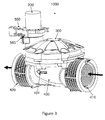
- the valve ( 1000 ) comprises a body ( 400 ) with inlet ( 410 ) and outlet ( 420 ).
- the direction of water flow is from inlet ( 410 ) to outlet ( 420 ), as shown by the heavy arrows and, representationally, by the outlined arrow ( 401 ) on the body ( 400 ).
- the device further comprises a cover ( 300 ) and a manual control means ( 550 ).
- an actuator ( 200 ) typically a solenoid, is attached to the device to automatically control water flow; the device can be supplied without solenoid and the user can supply one.
- a cross-section of the device is shown in the automatic-control position ( 1030 ), with the diaphragm ( 600 ) lifted so that liquid can flow through the valve.
- the actuator ( 200 ) is not shown.
- the diaphragm ( 600 ) is in a raised position; liquid flows ( 1100 ) from the inlet ( 410 ), over the edge of the barrier ( 450 ), and through the outlet ( 420 ).
- the diaphragm ( 600 ) has a small hole in it ( 610 ); the hole can be at any convenient position and need not be at the location indicated conceptually in Fig. 4 .
- the hole ( 610 ) enables water to pass into the diaphragm space ( 650 ) between the diaphragm ( 600 ) and the cover ( 300 ) and keeps the diaphragm space ( 650 ) filled with water.
- the body ( 400 ) has a second hole ( 430 ) which is blockable by the selector ( 500 ).
- liquid can not flow of the diaphragm space ( 650 ), pressure behind the diaphragm ( 600 ) rises, and the diaphragm ( 600 ) seals against the barrier ( 450 ), blocking flow from inlet ( 410 ) to outlet ( 420 ).
- the body hole ( 430 ) is fluidly connected to the automatic operation hole ( 510 ) in the selector ( 500 ) for the solenoid.
- This hole connects the diaphragm space ( 650 ) with a well ( 530 ) in the selector ( 500 ), the well ( 530 ) being fluidly connected with the nozzle gate ( 542 ) of the bore ( 540 ) of the selector ( 500 ), with the bottom end ( 544 ) of the bore ( 540 ) being fluidly connected to the outlet ( 420 ).
- the plunger ( 210 , not shown) If the plunger ( 210 , not shown) is in contact with the nozzle gate ( 542 ) of the bore ( 540 ), it blocks liquid flow from the diaphragm space ( 650 ) to the outlet ( 420 ), thereby, as described above, causing the diaphragm to lower and stopping flow ( 1100 ) between inlet ( 410 ) and outlet ( 420 ).
- the flow is outside-in, such that the liquid flow path in the region of the actuator is from the outside to the inside, in this case, from the well ( 530 ) into the bore ( 540 ).
- the flow would be from the diaphragm space ( 650 ) through the bore ( 540 ) to the well ( 530 ), and from thence into the outlet ( 420 ).
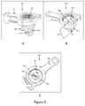
- the selector ( 500 ) is shown in Fig. 5A-C.
- Fig. 5A shows the selector ( 500 ) from the side, showing the main section ( 560 ) and the manual control means ( 550 ), in this embodiment, a lever.
- the manual control means ( 550 ) can be a knob, a button, a slider, or any other means known in the art for mechanically rotating the main section ( 560 ) about its main longitudinal axis, which is typically parallel to the bore ( 540 ) of the selector ( 500 ).
- the main section ( 560 ) comprises two liquid connection holes ( 510 , 520 ).
- the automatic operation hole ( 510 ) fluidly connects the diaphragm space ( 650 ) to the outlet ( 420 ) via the interior ( 530 ) of the main section ( 560 ), and the always-on hole ( 520 ) provides a fluid connection between the diaphragm space ( 650 ) and the outlet ( 420 ) which bypasses the interior ( 530 ) of the main section ( 560 ).
- Fig. 5B shows the selector ( 500 ) from an angle such that the interior ( 530 ) can be seen.
- the solenoid ( 200 in its closed position, blocks the nozzle gate ( 542 ) of the bore ( 540 ) of the selector ( 500 ). Therefore, in the solenoid's ( 200 ) closed position, the diaphragm space ( 650 ) has no fluid connection to the outlet ( 420 ) and no liquid flows.
- the solenoid ( 200 ) In use, in the solenoid's ( 200 , not shown) open position, the solenoid ( 200 ) does not block the bore ( 54 0), so that there can be a fluid connection between the diaphragm space ( 650 ) and the outlet ( 420 ) via the interior ( 530 ) of the base unit and the bore ( 540 ).
- That fluid connection is effectuated by the automatic operation hole ( 510 ); the water flows from the diaphragm space ( 650 ) via the body hole ( 430 , not shown) and the automatic operation hole ( 510 ) to the interior ( 530 ) of the main section ( 560 ), through the bore's nozzle gate ( 542 ) into the bore ( 540 ) and from thence into the outlet ( 420 , not shown), as shown by the dashed line ( 1200 ) in Fig. 4 .
- Fig. 5C shows the selector ( 500 ) from an angle such that the tubule ( 525 ) providing fluid connection between the diaphragm space ( 650 ) and the outlet ( 420 ) in the 'always on' setting can be seen.
- the always-on hole ( 520 , not shown) is connected to the bore ( 540 ) via the tubule ( 525 ).
- the tubule ( 525 ) is in the lower half of the main section ( 560 ).
- the liquid In the always-on position, the liquid never enters the interior ( 530 ) of the base unit; it flows directly from the diaphragm space ( 650 , not shown) through the always-on hole ( 520 , not shown) and the tubule ( 525 ) to the bore ( 540 ).
- the liquid enters the bore ( 540 ) from the side, typically in the lower half of the bore ( 540 ), and from thence passes to the outlet ( 420 ), bypassing completely the nozzle gate of the bore ( 542 ) and the automatic control unit contactable thereunto.
- Fig. 6 schematically illustrates the direction of liquid flow when the selector ( 500 ) is in the always-on position ( 1040 ).
- the heavy arrow ( 1100 ) shows the main liquid flow and the dashed line ( 1200 ), the direction of flow for allowing pressure reduction and opening of the diaphragm ( 600 ).
- the main flow as before, is from the inlet ( 410 ), over the barrier ( 450 ), and through the outlet ( 420 ).
- the pressure reduction flow ( 1200 ) passes through the diaphragm hole ( 610 , not shown), through the diaphragm space ( 650 ), and, via the body hole ( 430 ), the always-on hole ( 520 ), and the tubule ( 525 ), to the lower part of the bore ( 540 ), and, via the bottom end ( 544 ) of the bore into the outlet ( 420 ).
- Fig. 7 schematically illustrates the always-off configuration ( 1050 ).
- the selector ( 500 ) blocks ( 530 ) the body hole ( 430 ), thereby preventing liquid flow from the diaphragm space ( 650 ) to the outlet ( 420 ), thereby, as described above, keeping the diaphragm ( 600 ) sealed against the barrier ( 450 ) and preventing liquid flow from the inlet ( 410 ) to the outlet ( 420 ).
- the selector comprises at least one, and preferably three, check mechanisms.
- the check mechanism provides a positive indication that the selector is properly aligned to at least one position (always-on, always-off and automatic).
- a check mechanism can comprise any means known in the art, such as a stop, a detent, a catch, a pawl, a dog, a pin, a stud, a lever, and any combination thereof.
- the valve of the present invention is typically used to control flow of water, for example, in sprinkler or irrigation systems. It can also be used to control flow of any liquid of low viscosity, for example, oil, alcohol, milk, juice, tea, coffee, and any mixture of these with water.
- Table 3 comprises, for reference, a list of the numbers used herein and the portion of the device or the function of the device to which they refer.
- Table 3 A list of the numbers used herein and the portion of the device or the function of the device to which they refer.
Landscapes
- Engineering & Computer Science (AREA)
- General Engineering & Computer Science (AREA)
- Mechanical Engineering (AREA)
- Mechanically-Actuated Valves (AREA)
- Multiple-Way Valves (AREA)
- Fluid-Pressure Circuits (AREA)
Applications Claiming Priority (2)
| Application Number | Priority Date | Filing Date | Title |
|---|---|---|---|
| US14/044,012 US8881759B1 (en) | 2013-10-02 | 2013-10-02 | Manual selector for hydraulic control valve |
| IL228692A IL228692A (en) | 2013-10-02 | 2013-10-02 | Manual selector for hydraulic control valve |
Publications (2)
| Publication Number | Publication Date |
|---|---|
| EP2857729A2 true EP2857729A2 (de) | 2015-04-08 |
| EP2857729A3 EP2857729A3 (de) | 2015-04-29 |
Family
ID=52102370
Family Applications (1)
| Application Number | Title | Priority Date | Filing Date |
|---|---|---|---|
| EP20140187152 Withdrawn EP2857729A3 (de) | 2013-10-02 | 2014-09-30 | Manueller Wahlschalter für Hydrauliksteuerventil |
Country Status (1)
| Country | Link |
|---|---|
| EP (1) | EP2857729A3 (de) |
Citations (3)
| Publication number | Priority date | Publication date | Assignee | Title |
|---|---|---|---|---|
| US3500844A (en) | 1965-05-18 | 1970-03-17 | George E Sanner | Controls for lawn sprinkling systems and the like |
| US3865138A (en) | 1974-05-15 | 1975-02-11 | Wayne D Jones | Automatic sprinkler control device |
| EP0521485A2 (de) * | 1991-07-02 | 1993-01-07 | Bang Yan Wen | Automatisches Regelventil mit Trenneinrichtung zwischen Servoventil und Haptventil |
Family Cites Families (3)
| Publication number | Priority date | Publication date | Assignee | Title |
|---|---|---|---|---|
| US4893645A (en) * | 1988-11-07 | 1990-01-16 | L. R. Nelson Corporation | Control valve with improved dual mode operation and flow adjustment |
| US6263901B1 (en) * | 1999-05-26 | 2001-07-24 | The Toro Company | Self cleaning irrigation valve with offset manual on actuator, body/bonnet alignment, and captured screws |
| US8235352B2 (en) * | 2007-05-21 | 2012-08-07 | Rain Bird Corporation | Diaphragm valve for irrigation systems |
-
2014
- 2014-09-30 EP EP20140187152 patent/EP2857729A3/de not_active Withdrawn
Patent Citations (3)
| Publication number | Priority date | Publication date | Assignee | Title |
|---|---|---|---|---|
| US3500844A (en) | 1965-05-18 | 1970-03-17 | George E Sanner | Controls for lawn sprinkling systems and the like |
| US3865138A (en) | 1974-05-15 | 1975-02-11 | Wayne D Jones | Automatic sprinkler control device |
| EP0521485A2 (de) * | 1991-07-02 | 1993-01-07 | Bang Yan Wen | Automatisches Regelventil mit Trenneinrichtung zwischen Servoventil und Haptventil |
Also Published As
| Publication number | Publication date |
|---|---|
| EP2857729A3 (de) | 2015-04-29 |
Similar Documents
| Publication | Publication Date | Title |
|---|---|---|
| US8881759B1 (en) | Manual selector for hydraulic control valve | |
| DE60006928T2 (de) | Vorrichtung zum Abgeben und Mischen von Wasser | |
| DE4328064C2 (de) | Spülventil für Sanitärzwecke | |
| EP1130177B1 (de) | Wasserauslaufventilanordnung | |
| US8505566B2 (en) | Valve glue diverter | |
| DE19723312A1 (de) | Wassserauslaufventilanordnung | |
| EP2711560B1 (de) | Hydraulikantrieb für ein hydraulisch betätigbares Werkzeug | |
| DE4241023C2 (de) | Vorrichtung zur Verhinderung oder Verminderung der durch Waschbecken, Spülbecken, Badewannen o. dgl. verursachten Keime | |
| WO2008116242A1 (de) | Vorrichtung und verfahren zum kontrollieren der wassertemperatur an zumindest einem wasserausgang | |
| EP0367043B1 (de) | Sanitärarmatur mit Rohrunterbrecher | |
| DE4418088A1 (de) | Filter- und Beipaßöffnung für ein Spülventil | |
| EP0432440A1 (de) | Elektrisch gesteuerte Armatur | |
| DE69719196T2 (de) | Schwimmerventil | |
| US10571040B2 (en) | Irrigation valve with three-way solenoid actuation train | |
| EP2857729A2 (de) | Manueller Wahlschalter für Hydrauliksteuerventil | |
| EP4341498A1 (de) | Wasserauslaufarmatur mit spüleinrichtung | |
| CA2540944C (en) | Frost-proof exterior-wall valve | |
| IL228692A (en) | Manual selector for hydraulic control valve | |
| DE102015001208A1 (de) | Sanitärarmatur | |
| EP3877681B1 (de) | Wasserablenker und -verfahren | |
| DE3400545C2 (de) | ||
| DE19753101C2 (de) | Wasserversorgungsanlage | |
| DE102005061031B4 (de) | Wasserauslaufventilanordnung | |
| EP1502530B1 (de) | Ventilmechanismus für eine Brühvorrichtung | |
| DE3509720C2 (de) |
Legal Events
| Date | Code | Title | Description |
|---|---|---|---|
| PUAL | Search report despatched |
Free format text: ORIGINAL CODE: 0009013 |
|
| PUAI | Public reference made under article 153(3) epc to a published international application that has entered the european phase |
Free format text: ORIGINAL CODE: 0009012 |
|
| 17P | Request for examination filed |
Effective date: 20140930 |
|
| AK | Designated contracting states |
Kind code of ref document: A2 Designated state(s): AL AT BE BG CH CY CZ DE DK EE ES FI FR GB GR HR HU IE IS IT LI LT LU LV MC MK MT NL NO PL PT RO RS SE SI SK SM TR |
|
| AX | Request for extension of the european patent |
Extension state: BA ME |
|
| AK | Designated contracting states |
Kind code of ref document: A3 Designated state(s): AL AT BE BG CH CY CZ DE DK EE ES FI FR GB GR HR HU IE IS IT LI LT LU LV MC MK MT NL NO PL PT RO RS SE SI SK SM TR |
|
| AX | Request for extension of the european patent |
Extension state: BA ME |
|
| RIC1 | Information provided on ipc code assigned before grant |
Ipc: F16K 31/385 20060101AFI20150324BHEP Ipc: F16K 31/40 20060101ALI20150324BHEP |
|
| R17P | Request for examination filed (corrected) |
Effective date: 20151029 |
|
| RBV | Designated contracting states (corrected) |
Designated state(s): AL AT BE BG CH CY CZ DE DK EE ES FI FR GB GR HR HU IE IS IT LI LT LU LV MC MK MT NL NO PL PT RO RS SE SI SK SM TR |
|
| STAA | Information on the status of an ep patent application or granted ep patent |
Free format text: STATUS: EXAMINATION IS IN PROGRESS |
|
| 17Q | First examination report despatched |
Effective date: 20170807 |
|
| GRAP | Despatch of communication of intention to grant a patent |
Free format text: ORIGINAL CODE: EPIDOSNIGR1 |
|
| STAA | Information on the status of an ep patent application or granted ep patent |
Free format text: STATUS: GRANT OF PATENT IS INTENDED |
|
| INTG | Intention to grant announced |
Effective date: 20180629 |
|
| STAA | Information on the status of an ep patent application or granted ep patent |
Free format text: STATUS: THE APPLICATION IS DEEMED TO BE WITHDRAWN |
|
| 18D | Application deemed to be withdrawn |
Effective date: 20181110 |