EP2857731A1 - Vorpressrohr - Google Patents
Vorpressrohr Download PDFInfo
- Publication number
- EP2857731A1 EP2857731A1 EP14186344.9A EP14186344A EP2857731A1 EP 2857731 A1 EP2857731 A1 EP 2857731A1 EP 14186344 A EP14186344 A EP 14186344A EP 2857731 A1 EP2857731 A1 EP 2857731A1
- Authority
- EP
- European Patent Office
- Prior art keywords
- tube
- prepress
- layer
- fiber composite
- composite material
- Prior art date
- Legal status (The legal status is an assumption and is not a legal conclusion. Google has not performed a legal analysis and makes no representation as to the accuracy of the status listed.)
- Granted
Links
- 229920005989 resin Polymers 0.000 claims abstract description 27
- 239000011347 resin Substances 0.000 claims abstract description 27
- 230000006835 compression Effects 0.000 claims abstract description 26
- 238000007906 compression Methods 0.000 claims abstract description 26
- 239000000835 fiber Substances 0.000 claims abstract description 25
- 239000002131 composite material Substances 0.000 claims abstract description 17
- 239000004567 concrete Substances 0.000 claims abstract description 14
- 239000000463 material Substances 0.000 claims abstract description 13
- 239000000126 substance Substances 0.000 claims abstract description 7
- 239000011159 matrix material Substances 0.000 claims abstract description 6
- 239000010410 layer Substances 0.000 claims description 31
- IISBACLAFKSPIT-UHFFFAOYSA-N bisphenol A Chemical compound C=1C=C(O)C=CC=1C(C)(C)C1=CC=C(O)C=C1 IISBACLAFKSPIT-UHFFFAOYSA-N 0.000 claims description 8
- 239000002344 surface layer Substances 0.000 claims description 8
- 238000000576 coating method Methods 0.000 claims description 7
- 239000004645 polyester resin Substances 0.000 claims description 7
- 229920001225 polyester resin Polymers 0.000 claims description 7
- 230000005540 biological transmission Effects 0.000 claims description 6
- 229910052500 inorganic mineral Inorganic materials 0.000 claims description 6
- 239000011707 mineral Substances 0.000 claims description 6
- 239000003513 alkali Substances 0.000 claims description 4
- 239000011248 coating agent Substances 0.000 claims description 4
- 230000002093 peripheral effect Effects 0.000 claims description 4
- 239000003365 glass fiber Substances 0.000 claims description 3
- 229910000831 Steel Inorganic materials 0.000 claims description 2
- 239000003822 epoxy resin Substances 0.000 claims description 2
- 229920000647 polyepoxide Polymers 0.000 claims description 2
- 229920006395 saturated elastomer Polymers 0.000 claims description 2
- 239000010959 steel Substances 0.000 claims description 2
- 229920001567 vinyl ester resin Polymers 0.000 claims description 2
- 229940106691 bisphenol a Drugs 0.000 claims 2
- 238000005096 rolling process Methods 0.000 claims 1
- 239000000945 filler Substances 0.000 description 4
- 239000011150 reinforced concrete Substances 0.000 description 3
- 238000007127 saponification reaction Methods 0.000 description 3
- 238000007689 inspection Methods 0.000 description 2
- 238000009434 installation Methods 0.000 description 2
- 238000004519 manufacturing process Methods 0.000 description 2
- 238000000034 method Methods 0.000 description 2
- 239000004576 sand Substances 0.000 description 2
- 239000004971 Cross linker Substances 0.000 description 1
- 238000010521 absorption reaction Methods 0.000 description 1
- 238000004891 communication Methods 0.000 description 1
- 230000002706 hydrostatic effect Effects 0.000 description 1
- 239000012764 mineral filler Substances 0.000 description 1
- 229920005906 polyester polyol Polymers 0.000 description 1
- 239000004814 polyurethane Substances 0.000 description 1
- 229920002635 polyurethane Polymers 0.000 description 1
- 238000003825 pressing Methods 0.000 description 1
Images


Classifications
-
- F—MECHANICAL ENGINEERING; LIGHTING; HEATING; WEAPONS; BLASTING
- F16—ENGINEERING ELEMENTS AND UNITS; GENERAL MEASURES FOR PRODUCING AND MAINTAINING EFFECTIVE FUNCTIONING OF MACHINES OR INSTALLATIONS; THERMAL INSULATION IN GENERAL
- F16L—PIPES; JOINTS OR FITTINGS FOR PIPES; SUPPORTS FOR PIPES, CABLES OR PROTECTIVE TUBING; MEANS FOR THERMAL INSULATION IN GENERAL
- F16L9/00—Rigid pipes
- F16L9/08—Rigid pipes of concrete, cement, or asbestos cement, with or without reinforcement
- F16L9/085—Reinforced pipes
-
- B—PERFORMING OPERATIONS; TRANSPORTING
- B32—LAYERED PRODUCTS
- B32B—LAYERED PRODUCTS, i.e. PRODUCTS BUILT-UP OF STRATA OF FLAT OR NON-FLAT, e.g. CELLULAR OR HONEYCOMB, FORM
- B32B1/00—Layered products having a non-planar shape
- B32B1/08—Tubular products
-
- B—PERFORMING OPERATIONS; TRANSPORTING
- B32—LAYERED PRODUCTS
- B32B—LAYERED PRODUCTS, i.e. PRODUCTS BUILT-UP OF STRATA OF FLAT OR NON-FLAT, e.g. CELLULAR OR HONEYCOMB, FORM
- B32B13/00—Layered products comprising a a layer of water-setting substance, e.g. concrete, plaster, asbestos cement, or like builders' material
- B32B13/14—Layered products comprising a a layer of water-setting substance, e.g. concrete, plaster, asbestos cement, or like builders' material next to a fibrous or filamentary layer
-
- B—PERFORMING OPERATIONS; TRANSPORTING
- B32—LAYERED PRODUCTS
- B32B—LAYERED PRODUCTS, i.e. PRODUCTS BUILT-UP OF STRATA OF FLAT OR NON-FLAT, e.g. CELLULAR OR HONEYCOMB, FORM
- B32B5/00—Layered products characterised by the non- homogeneity or physical structure, i.e. comprising a fibrous, filamentary, particulate or foam layer; Layered products characterised by having a layer differing constitutionally or physically in different parts
- B32B5/22—Layered products characterised by the non- homogeneity or physical structure, i.e. comprising a fibrous, filamentary, particulate or foam layer; Layered products characterised by having a layer differing constitutionally or physically in different parts characterised by the presence of two or more layers which are next to each other and are fibrous, filamentary, formed of particles or foamed
- B32B5/24—Layered products characterised by the non- homogeneity or physical structure, i.e. comprising a fibrous, filamentary, particulate or foam layer; Layered products characterised by having a layer differing constitutionally or physically in different parts characterised by the presence of two or more layers which are next to each other and are fibrous, filamentary, formed of particles or foamed one layer being a fibrous or filamentary layer
- B32B5/26—Layered products characterised by the non- homogeneity or physical structure, i.e. comprising a fibrous, filamentary, particulate or foam layer; Layered products characterised by having a layer differing constitutionally or physically in different parts characterised by the presence of two or more layers which are next to each other and are fibrous, filamentary, formed of particles or foamed one layer being a fibrous or filamentary layer another layer next to it also being fibrous or filamentary
-
- B—PERFORMING OPERATIONS; TRANSPORTING
- B32—LAYERED PRODUCTS
- B32B—LAYERED PRODUCTS, i.e. PRODUCTS BUILT-UP OF STRATA OF FLAT OR NON-FLAT, e.g. CELLULAR OR HONEYCOMB, FORM
- B32B7/00—Layered products characterised by the relation between layers; Layered products characterised by the relative orientation of features between layers, or by the relative values of a measurable parameter between layers, i.e. products comprising layers having different physical, chemical or physicochemical properties; Layered products characterised by the interconnection of layers
- B32B7/04—Interconnection of layers
- B32B7/12—Interconnection of layers using interposed adhesives or interposed materials with bonding properties
-
- F—MECHANICAL ENGINEERING; LIGHTING; HEATING; WEAPONS; BLASTING
- F16—ENGINEERING ELEMENTS AND UNITS; GENERAL MEASURES FOR PRODUCING AND MAINTAINING EFFECTIVE FUNCTIONING OF MACHINES OR INSTALLATIONS; THERMAL INSULATION IN GENERAL
- F16L—PIPES; JOINTS OR FITTINGS FOR PIPES; SUPPORTS FOR PIPES, CABLES OR PROTECTIVE TUBING; MEANS FOR THERMAL INSULATION IN GENERAL
- F16L9/00—Rigid pipes
- F16L9/14—Compound tubes, i.e. made of materials not wholly covered by any one of the preceding groups
-
- B—PERFORMING OPERATIONS; TRANSPORTING
- B32—LAYERED PRODUCTS
- B32B—LAYERED PRODUCTS, i.e. PRODUCTS BUILT-UP OF STRATA OF FLAT OR NON-FLAT, e.g. CELLULAR OR HONEYCOMB, FORM
- B32B2260/00—Layered product comprising an impregnated, embedded, or bonded layer wherein the layer comprises an impregnation, embedding, or binder material
- B32B2260/02—Composition of the impregnated, bonded or embedded layer
- B32B2260/021—Fibrous or filamentary layer
-
- B—PERFORMING OPERATIONS; TRANSPORTING
- B32—LAYERED PRODUCTS
- B32B—LAYERED PRODUCTS, i.e. PRODUCTS BUILT-UP OF STRATA OF FLAT OR NON-FLAT, e.g. CELLULAR OR HONEYCOMB, FORM
- B32B2260/00—Layered product comprising an impregnated, embedded, or bonded layer wherein the layer comprises an impregnation, embedding, or binder material
- B32B2260/04—Impregnation, embedding, or binder material
- B32B2260/046—Synthetic resin
-
- B—PERFORMING OPERATIONS; TRANSPORTING
- B32—LAYERED PRODUCTS
- B32B—LAYERED PRODUCTS, i.e. PRODUCTS BUILT-UP OF STRATA OF FLAT OR NON-FLAT, e.g. CELLULAR OR HONEYCOMB, FORM
- B32B2262/00—Composition or structural features of fibres which form a fibrous or filamentary layer or are present as additives
- B32B2262/10—Inorganic fibres
- B32B2262/101—Glass fibres
-
- B—PERFORMING OPERATIONS; TRANSPORTING
- B32—LAYERED PRODUCTS
- B32B—LAYERED PRODUCTS, i.e. PRODUCTS BUILT-UP OF STRATA OF FLAT OR NON-FLAT, e.g. CELLULAR OR HONEYCOMB, FORM
- B32B2605/00—Vehicles
Definitions
- the invention relates to a walk-in pre-compression tube, in particular for the transport of aggressive media, comprising an inner tube made of a chemical-resistant material and an outer tube made of concrete.
- Prepress pipes are used in pipe jacking, ie in a method for trenchless laying of pipes.
- a walk-through pre-compression tube is understood to mean a pre-compression tube having a nominal diameter of at least 1400 mm.
- pre-pressure pipes are usually made of concrete or reinforced concrete. These materials have sufficient stability to absorb the occurring normal forces.
- concrete-based pipes are only partially suitable for the transport of some aggressive media. The aggressive media can attack the concrete material and the structural stability of the pre-compression pipes can be affected.
- the present invention has for its object to provide a Vorpressrohr, ie a pipe which can be laid in the pipe jacking, which is suitable for the transport of aggressive media and can be produced and laid in a simple and economical manner.
- a Vorpressrohr of the aforementioned type that according to the invention is characterized in that the inner tube is formed by a fiber composite, that the fiber composite material has at least one supporting layer, which 50 wt .-% to 80 wt .-% of fibers which are wound in a circumferential direction and / or helical, and also multi-layered and that the supporting layer 20 wt .-% to 40 wt .-% of matrix material which is based on reactive resin, that the fiber composite material has a radially outer surface layer, which comprises at least 70% by weight of alkali-resistant reactive resin, in particular substantially completely saturated reactive resin, and in that the outer tube of concrete is cast onto the fully reacted radially outer surface layer.
- the pre-compression tube according to the invention has the advantage that during pipe jacking in the direction of advance, i. occurring in the tube longitudinal direction normal forces are absorbed by the outer tube made of concrete, while the inner tube by its nature provides a high resistance to chemicals induced material damage.
- the inventive nature of the inner tube also ensures that the inner tube forces that act in the installed state, in particular in the radial direction of the tube, even in case of failure or damage to the outer tube can accommodate.
- a force is for example hydrostatic pressure, which is relevant when laying at great depths.
- the inner tube is therefore self-supporting in the installed state.
- the supporting layer comprises, based on the weight of the supporting layer, up to 20% by weight, in particular 10% by weight to 20% by weight, of fibers which run essentially along a longitudinal direction of the pre-pressing tube ,
- a pre-compression tube which comprises fibers of the aforementioned orientation, has advantageous mechanical properties, in particular normal forces, ie forces along the longitudinal direction, can be absorbed by the inner tube.
- the alkali-resistant reactive resin of the radially outer surface layer is a bisphenol A-based reactive resin, in particular a bisphenol A-based vinyl ester resin.
- Reactive resins of the type just mentioned are particularly resistant to alkaline media.
- the radially outer surface layer of the inner tube is in contact with the outer tube, which is made of concrete. Moisture makes components of the concrete alkaline. With unsuitable reactive resins, this can lead to a saponification reaction of the reactive resin. Such saponification leads to increased material damage of the inner tube. This allows the mechanical integrity of the inner tube are affected.
- the use of said reactive resins according to the invention reliably prevents such a saponification reaction.
- the inner tube comprises ECR glass fibers.
- ECR glass fibers have a particularly high chemical resistance.
- the matrix material of the supporting layer is a polyester resin.
- the use of a polyester resin enables an economical production of the preform tube according to the invention.
- the pre-compression tube can advantageously have on an inner side of the supporting layer a further layer which comprises a resin, in particular a polyester resin, and a random fiber web.
- a resin in particular a polyester resin
- a random fiber web a resin, in particular a polyester resin
- the above-mentioned further layer according to the invention offers a further improved protection of the inner tube from chemical-induced material damage and mechanical stress by the aggressive media transported in the pre-compression tube. It is thus prevented that the bearing layer is exposed to harmful influences.
- the pre-compression tube has at least one circumferential seal, in particular a sliding seal or a rolling-ring seal in the region of a spigot end, which is arranged circumferentially on a radially outer surface of the spigot end in the circumferential direction.
- a circumferential seal prevents leakage of the medium to be transported in the pipeline.
- a pre-compression tube which has at least two peripheral seals in the region of a spigot, which in the circumferential direction circumferentially on a radially outer surface of the spigot end in an axial Spaced apart, so that between the peripheral seals an annular space is formed.
- at least one test opening is provided which extends inwards from the annular space and opens into an inner surface of the pre-press pipe.
- the tightness of the annulus limiting circumferential seals can be checked in the installed state.
- an end face of a spigot end and an end face of a stub end of the pre-compression tube have a thin-bed coating based on epoxy resin.
- a further preferred embodiment of the pre-compression tube is characterized in that the fiber composite material has interference, in particular mineral interference, which are visually detectable with respect to the fiber composite material, and in particular are black.
- the said mineral interference according to the invention allow orientation of an automated inspection system for checking the laid pipe, for example for damage.
- an inner surface of the pre-press tube is formed by a nonwoven-reinforced resin layer which comprises at least 80% by weight of reactive resin, in particular polyester resin.
- the aforementioned nonwoven reinforced resin layer is particularly resistant to corrosive media.
- the pre-compression tube has a cylindrical sleeve, in particular of steel, at one end of the stub.
- This cylindrical cuff is supported a flush and coaxial installation of several pre-pressure pipes to a pipe string.
- the sleeve is anchored in a form-fitting manner in the outer tube, preferably, a fastening element of the sleeve is cast into the outer tube.
- the inner surface of the inner tube has a roughness, so that the inner surface has a coefficient of friction of at least 0.7. Such roughness allows the use of automated mobile inspection systems in the pre-compression tube and provides a good "grip" for this purpose.
- the coefficient of friction is determined here on a plane with an adjustable, readable inclination angle.
- the level consists of a plate, which has the same structure as the corresponding inner tube.
- a specimen with a smooth surface made of VULKOLLAN 18 is placed on the plane.
- VULKOLLAN 18 is a polyurethane material from Bayer, which is produced by polyaddition using only Desmodur 15, polyester polyol and a crosslinker.
- the inclination angle of the plane is increased. An inclination angle at which the test piece begins to slip down the plane is measured.
- the coefficient of friction corresponds to the tangent of the angle of inclination at which the test piece begins to slip down the plane.
- the outer tube of the pre-compression tube is made using reinforced concrete.
- reinforced concrete for the production of the outer tube allows the absorption of large normal forces in the pipe jacking.
- Vorpressrohrstrang which comprises a plurality of coaxially extending Vorpressrohre invention, in which in a laid state an end face of a butt end of a first pre-compression tube is spaced from an end face of a tip end of a second pre-compression tube.
- Vorpressrohrstrangs invention is in the installed state in each case a force transmission element, between the end face of the stub end of the first Vorpressrohres and the end face of the spigot end of the second Vorpressrohres arranged and preferably only between the outer tubes made of concrete.
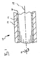
- FIG. 1 shows a schematic size not scaled sectional view of a Vorpressrohrs invention 10
- the pre-compression tube 10 comprises an inner tube 12 which is formed of a chemical resistant fiber composite material 13 and an outer tube 14 made of concrete.
- a circumferential direction is designated by the reference numeral 16 and a longitudinal axis of the pre-press tube bears the reference numeral 18.
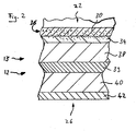
- FIG. 2 shows a detailed schematic representation of an enlarged portion of the inner tube 12 from FIG. 1 ,
- the inner tube 12 forming fiber composite material 13 is constructed multi-layered. Viewed from an inner side 22 to an outer side 26, the fiber composite material 13 and thus also the inner tube are constructed of a flow-reinforced resin layer 30, a further layer 34, wherein the flow-reinforced resin layer 30 and the further layer 34 comprise punctiform mineral interferences 36, one first supporting layer 38, a filler layer 39 and a second supporting layer 40, and a radially outer surface layer 42.
- the filler layer comprises sand which is embedded in a reactive resin matrix. However, the sand of such a filler layer 39 can also be replaced by other filler materials, in particular mineral fillers.
- the mineral interspersions 36 may be contained in each of the layers 30, 34, 38, 39, 40, 42 of the fiber composite material 13.
- the mineral interspersions 36 are preferably contained at least in the flow-reinforced resin layer 30 and / or the further layer 34.
- FIG. 3 shows a spigot 46 and a butt end 50 of a pre-compression tube 10.
- An end face 54 of the spigot 46 has a thin bed coating 56.
- An end face 58 of the butt end 50 has a thin-bed coating 60.
- a cylindrical sleeve 64 is arranged.
- the cylindrical sleeve 64 is fastened via a fastening element 68, which is cast into the outer tube 14.
- a first circumferential seal 72 and a second circumferential seal 73 are circumferentially arranged in the circumferential direction 16. Between the peripheral seals 72, 73 an annular space 76 is formed. From the annular space 76, a test opening 80 extends and opens into an inner surface 82 of the Vorpressrohrs 10th
- FIG. 4 shows the connection of a first Vorpressrohrs 10a with a second Vorpressrohr 10b to a Vorpressrohrstrang 11 according to the invention.
- Corresponding reference numerals are related by the addition of a or b to the respective tube 10a, 10b.
- the butt end 50a of the first pre-compression tube 10a is in operative communication with the spigot end 46b of the second pre-compression tube 10b.
- the spigot 46b is inserted into the cylindrical sleeve 64a.
- a force transmission element 84 is arranged between the thin-bed coatings 58a, 54b of the two tubes 10a, 10b.
- the second pipe 10b pushes the first pipe 10a forward via contact by means of the power transmission element 84.
- the medium to be transported flows through the tube interior spaces 82a and 82b.
- the medium to be transported comes into contact with the inner tubes 12a, 12b and the thin-bed coatings 58, 54.
- the inner tubes 12a, b in cooperation with the thin-bed coatings 58a, 54b and the circumferential seals 72b, 73b and the cylindrical sleeve 64, prevent the medium to be transported from coming into contact with the outer tube 14. As a result, damage to the material of the outer tube 14 is prevented.
Landscapes
- Engineering & Computer Science (AREA)
- General Engineering & Computer Science (AREA)
- Mechanical Engineering (AREA)
- Structural Engineering (AREA)
- Rigid Pipes And Flexible Pipes (AREA)
- Laminated Bodies (AREA)
Abstract
Description
- Die Erfindung betrifft ein begehbares Vorpressrohr, insbesondere zum Transport von aggressiven Medien, umfassend ein Innenrohr aus einem chemikalienbeständigen Material und ein Außenrohr aus Beton.
- Vorpressrohre werden beim Rohrvortrieb, also bei einer Methode zum grabenlosen Verlegen von Rohren, verwendet. Unter einem begehbaren Vorpressrohr versteht man hierbei ein Vorpressrohr mit einem Nenndurchmesser von mindestens 1400mm. Beim Rohrvortrieb wird, zumeist ausgehend von einem Vertikalschacht, eine dem geplanten Rohrverlauf entsprechende Medienleitung mittels einer Tunnelbohrmaschine ins Erdreich eingebracht. Eine solche Medienleitung verläuft teilweise in großen Tiefen. Der Tunnelbohrmaschine direkt folgend werden die Vorpressrohre in den Vertikalschacht abgelassen, eingebaut und anschließend vorgepresst. Die vorangegangenen Rohre werden dabei jeweils von den nachfolgenden Rohren vorwärts geschoben bzw. getrieben. Durch diese Verlegetechnik entfallen ein Ausheben und ein dem Verlegen folgendes Zuschütten eines Grabens, was ein Verlegen in großen Verlegetiefen erst ermöglicht. Bei einem solchen Rohrvortrieb treten hohe Normalkräfte auf, welche durch das Rohrmaterial aufgenommen werden müssen. Herkömmliche Vorpressrohre sind üblicherweise aus Beton oder Stahlbeton gefertigt. Diese Werkstoffe haben eine ausreichende Stabilität, um die auftretenden Normalkräfte aufzunehmen. Betonbasierte Rohre sind jedoch nur bedingt für den Transport mancher aggressiver Medien geeignet. Die aggressiven Medien können den Betonwerkstoff angreifen und die strukturelle Beständigkeit der Vorpressrohre kann hierdurch beeinträchtigt werden.
- Der vorliegenden Erfindung liegt die Aufgabe zugrunde, ein Vorpressrohr zu schaffen, also ein Rohr, welches im Rohrvortrieb verlegt werden kann, welches sich zum Transport von aggressiven Medien eignet und auf einfache und wirtschaftliche Weise herstellbar und verlegbar ist.
- Diese Aufgabe wird durch ein Vorpressrohr der eingangs genannten Art gelöst, dass erfindungsgemäß dadurch gekennzeichnet ist, dass das Innenrohr von einem Faserverbundwerkstoff gebildet ist, dass der Faserverbundwerkstoff mindestens eine tragende Schicht aufweist, welche 50 Gew.-% bis 80 Gew.-% an Fasern umfasst, die in einer Umfangsrichtung und/oder schraubenförmig, und zudem mehrlagig gewickelt sind und dass die tragende Schicht 20 Gew.-% bis 40 Gew.-% an Matrixmaterial umfasst, welches auf Reaktivharz basiert, dass der Faserverbundwerkstoff eine radial äußere Oberflächenschicht aufweist, welche mindestens 70 Gew.-% an alkalibeständigem Reaktivharz, insbesondere an im Wesentlichen vollständig gesättigtem Reaktivharz, umfasst, und dass das Außenrohr aus Beton an die vollständig ausreagierte radial äußere Oberflächenschicht angegossen ist.
- Das erfindungsgemäße Vorpressrohr hat den Vorteil, dass beim Rohrvortrieb in Vortriebsrichtung, d.h. in Rohrlängsrichtung auftretende Normalkräfte durch das Außenrohr aus Beton aufgenommen werden, während das Innenrohr durch seine Beschaffenheit eine hohe Resistenz gegen chemikalieninduzierte Werkstoffschädigung bietet. Die erfindungsgemäße Beschaffenheit des Innenrohrs gewährleistet überdies, dass das Innenrohr Kräfte, welche im verlegten Zustand insbesondere in radialer Richtung auf das Rohr wirken, auch bei Ausfall oder Beschädigung des Außenrohrs aufnehmen kann. Eine solche Kraft ist beispielsweise hydrostatischer Druck, welcher bei Verlegung in großen Tiefen relevant ist. Das Innenrohr ist daher im verlegten Zustand selbsttragend.
- Nach einer bevorzugten Ausführungsform der vorliegenden Erfindung umfasst die tragende Schicht bezogen auf das Gewicht der tragenden Schicht bis zu 20 Gew.-%, insbesondere 10 Gew.-% bis 20 Gew.-% an Fasern, welche im Wesentlichen entlang einer Längsrichtung des Vorpressrohrs verlaufen. Ein Vorpressrohr, welches Fasern der eben genannten Ausrichtung umfasst, besitzt vorteilhafte mechanische Eigenschaften, insbesondere können Normalkräfte, also Kräfte entlang der Längsrichtung durch das Innenrohr aufgenommen werden.
- Nach einer weiteren bevorzugten Ausführungsform der Erfindung ist das alkalibeständige Reaktivharz der radial äußeren Oberflächenschicht ein Bisphenol-A-basiertes Reaktivharz, insbesondere ein Bisphenol-A-basiertes Vinylesterharz. Reaktivharze der eben genannten Art sind besonders beständig gegen alkalische Medien. Die radial äußere Oberflächenschicht des Innenrohres steht in Kontakt mit dem Außenrohr, welches aus Beton ist. Feuchtigkeit lässt Bestandteile des Betons alkalisch wirken. Bei ungeeigneten Reaktivharzen kann es dadurch zu einer Verseifungsreaktion des Reaktivharzes kommen. Eine solche Verseifung führt zu einer erhöhten Werkstoffschädigung des Innenrohres. Hierdurch kann die mechanische Integrität des Innenrohres beeinträchtigt werden. Die Verwendung der genannten erfindungsgemäßen Reaktivharze verhindert eine solche Verseifungsreaktion zuverlässig.
- Als vorteilhaft hat sich ebenso erwiesen, wenn das Innenrohr ECR-Glasfasern umfasst. ECR-Glasfasern weisen eine besonders hohe Chemikalienbeständigkeit auf.
- Erfindungsgemäß ist ebenso, dass das Matrixmaterial der tragenden Schicht ein Polyesterharz ist. Die Verwendung eines Polyesterharzes ermöglicht eine wirtschaftliche Herstellung des erfindungsgemäßen Vorpressrohrs.
- Das Vorpressrohr kann vorteilhafter Weise auf einer Innenseite der tragenden Schicht eine weitere Schicht aufweisen, welche ein Harz, insbesondere ein Polyesterharz, und ein Wirrfasergelege umfasst. Die eben genannte erfindungsgemäße weitere Schicht bietet einen weiter verbesserten Schutz des Innenrohres vor chemikalienbedingter Werkstoffschädigung und mechanischer Beanspruchung durch die in dem Vorpressrohr transportierten aggressiven Medien. Es wird also verhindert, dass die tragende Schicht schädigenden Einflüssen ausgesetzt wird.
- Als vorteilhaft hat sich des Weiteren erwiesen, dass das Vorpressrohr im Bereich eines Spitzendes mindestens eine Umfangsdichtung, insbesondere eine Gleitkeildichtung oder eine Rollringdichtung, aufweist, welche in der Umfangsrichtung umlaufend auf einer radial äußeren Oberfläche des Spitzendes angeordnet ist. Durch eine solche Umfangsdichtung wird eine Leckage des in der Rohrleitung zu transportierenden Mediums verhindert.
- Im Sinne der Erfindung ist auch ein Vorpressrohr, das im Bereich eines Spitzendes mindestens zwei Umfangsdichtungen aufweist, welche in der Umfangsrichtung umlaufend auf einer radial äußeren Oberfläche des Spitzendes in einem axialen Abstand zueinander angeordnet sind, so dass zwischen den Umfangsdichtungen ein Ringraum gebildet ist. Vorteilhafterweise ist von dem Ringraum ausgehend mindestens eine Prüföffnung vorgesehen, die sich von dem Ringraum nach innen erstreckt und in einer Innenoberfläche des Vorpressrohrs mündet. Über die Prüföffnung kann die Dichtigkeit der den Ringraum begrenzenden Umfangsdichtungen im verlegten Zustand geprüft werden.
- Vorteilhaft ist ebenso, wenn eine Stirnfläche eines Spitzendes und eine Stirnfläche eines Stumpfendes des Vorpressrohres eine Dünnbettbeschichtung auf Epoxidharzbasis aufweisen. Hierdurch wird eine Werkstoffschädigung des Außenrohrs aus Beton aufgrund von Kontakt mit den transportierten aggressiven Medien verhindert.
- Eine weitere bevorzugte Ausführungsform des Vorpressrohrs zeichnet sich dadurch aus, dass der Faserverbundwerkstoff Einstreuungen, insbesondere mineralische Einstreuungen aufweist, die gegenüber dem Faserverbundwerkstoff optisch erfassbar sind, und insbesondere schwarz sind. Die genannten erfindungsgemäßen mineralischen Einstreuungen erlauben eine Orientierung eines automatisierten Inspektionssystems zur Kontrolle des verlegten Rohrs, beispielsweise auf Schädigungen.
- Als vorteilhaft hat sich ebenso erwiesen, wenn eine innere Oberfläche des Vorpressrohrs durch eine vliesverstärkte Harzschicht gebildet ist, welche mindestens 80 Gew.-% Reaktivharz insbesondere Polyesterharz umfasst. Die genannte vliesverstärkte Harzschicht ist besonders resistent gegen korrosive Medien.
- Im Sinne der Erfindung ist es ebenso, dass das Vorpressrohr an einem Stumpfende eine zylindrische Manschette, insbesondere aus Stahl aufweist. Diese zylindrische Manschette unterstützt eine bündige und koaxiale Verlegung mehrerer Vorpressrohre zu einem Rohrstrang.
- Als besonders vorteilhaft hat sich herausgestellt, wenn die Manschette formschlüssig in dem Außenrohr verankert ist, vorzugsweise, ein Befestigungselement der Manschette in das Außenrohr eingegossen ist.
- Als vorteilhaft hat sich ebenso erwiesen, wenn die innere Oberfläche des Innenrohrs eine Rauigkeit aufweist, so dass die innere Oberfläche eine Reibungszahl von mindestens 0,7 aufweist. Eine solche Rauigkeit ermöglicht die Verwendung von automatisierten fahrbaren Inspektionssystemen in dem Vorpressrohr und bietet hierfür einen guten "Grip".
- Die Reibungszahl wird hierbei an einer Ebene mit verstellbarem, ablesbarem Neigungswinkel ermittelt. Die Ebene besteht aus einer Platte, die den gleichen Aufbau aufweist wie das entsprechende Innenrohr. Ein Prüfkörper mit einer glatten Oberfläche aus VULKOLLAN 18 wird auf der Ebene platziert. VULKOLLAN 18 ist ein Polyurethan-Werkstoff der Firma Bayer, welcher durch Polyaddition unter ausschließlicher Verwendung von Desmodur 15, Polyester-Polyol und einem Vernetzer hergestellt wird. Der Neigungswinkel der Ebene wird erhöht. Ein Neigungswinkel bei welchem der Prüfkörper beginnt die Ebene herabzurutschen wird gemessen. Die Reibungszahl entspricht dem Tangens des Neigungswinkels, bei welchem der Prüfkörper beginnt, die Ebene herabzurutschen.
- In einer bevorzugten Ausführungsform ist das Außenrohr des Vorpressrohrs unter Verwendung von Stahlbeton hergestellt. Die Verwendung von Stahlbeton zur Herstellung des Außenrohrs ermöglicht im Rohrvortrieb die Aufnahme großer Normalkräfte.
- Im Sinne der Erfindung ist ebenso ein Vorpressrohrstrang, welcher mehrere koaxial verlaufende erfindungsgemäße Vorpressrohre umfasst, bei welchen in einem verlegten Zustand eine Stirnfläche eines Stumpfendes eines ersten Vorpressrohrs zu einer Stirnfläche eines Spitzendes eines zweiten Vorpressrohrs beabstandet angeordnet ist.
- In einer Weiterbildung des erfindungsgemäßen Vorpressrohrstrangs ist im verlegten Zustand jeweils ein Kraftübertragungselement, insbesondere eine Holzringscheibe, zwischen der Stirnfläche des Stumpfendes des ersten Vorpressrohres und der Stirnfläche des Spitzendes des zweiten Vorpressrohres angeordnet und zwar vorzugsweise nur zwischen den Außenrohren aus Beton.
- Die Verwendung eines solchen Kraftübertragungselements ermöglicht den beschädigungsfreien Vortrieb des erfindungsgemäßen Vorpressrohrstrangs, da durch das Kraftübertragungselement ein direkter Kontakt der Stirnflächen des Spitz- und des Stumpfendes und eine Krafteinwirkung auf das Innenrohr vermieden wird.
- Weitere Merkmale, Einzelheiten und Vorteile der Erfindung ergeben sich aus den beigefügten Patentansprüchen, der zeichnerischen Darstellung und nachfolgenden Beschreibung mehrerer bevorzugter Ausführungsformen des erfindungsgemäßen Vortriebsrohrs sowie des erfindungsgemäßen Vortriebsrohrstrangs.
- In der Zeichnung zeigt:
- Figur 1
- eine vereinfachte schematische Schnittansicht eines erfindungsgemäßen Vorpressrohres;
- Figur 2
- eine vergrößerte Schnittansicht eines Teils des Innenrohres aus
Figur 1 ; - Figur 3
- eine Schnittansicht eines Teils einer weiteren Ausführungsform eines erfindungsgemäßen Vorpressrohres; und
- Figur 4
- eine schematische Schnittansicht eines Teils eines Vorpressrohrstrangs.
-
Figur 1 zeigt eine schematische größenmäßig nicht skalierte Schnittansicht eines erfindungsgemäßen Vorpressrohrs 10. Das Vorpressrohr 10 umfasst ein Innenrohr 12, welches aus einem chemikalienbeständigen Faserverbundwerkstoff 13 gebildet ist und ein Außenrohr 14 aus Beton. Eine Umfangsrichtung trägt das Bezugszeichen 16 und eine Längsachse des Vorpressrohrs trägt das Bezugszeichen 18. -
Figur 2 zeigt eine detaillierte schematische Darstellung eines vergrößerten Bereichs des Innenrohres 12 ausFigur 1 . Der das Innenrohr 12 bildende Faserverbundwerkstoff 13 ist mehrschichtig aufgebaut. Von einer Innenseite 22 zu einer Außenseite 26 hin gesehen ist der Faserverbundwerkstoff 13 und damit auch das Innenrohr aufgebaut aus, einer fließverstärkten Harzschicht 30, einer weiteren Schicht 34, wobei die fließverstärkte Harzschicht 30 und die weitere Schicht 34 punktförmig dargestellte mineralische Einstreuungen 36 umfassen, einer ersten tragenden Schicht 38, einer Füllstoffschicht 39 sowie einer zweiten tragenden Schicht 40, und einer radial äußeren Oberflächenschicht 42. Die Füllstoffschicht umfasst Sand, welcher in einer Reaktivharzmatrix eingebettet ist. Der Sand einer solchen Füllstoffschicht 39 kann jedoch ebenso durch andere Füllmaterialien, insbesondere mineralische Füllmaterialien ersetzt werden. Die mineralischen Einstreuungen 36 können in jeder der Schichten 30, 34, 38, 39, 40, 42 des Faserverbundwerkstoffs 13 enthalten sein. Bevorzugter Weise sind die mineralischen Einstreuungen 36 mindestens in der fließverstärkten Harzschicht 30 und/oder der weiteren Schicht 34 enthalten. -
Figur 3 zeigt ein Spitzende 46 sowie ein Stumpfende 50 eines Vorpressrohrs 10. Eine Stirnseite 54 des Spitzendes 46 weist eine Dünnbettbeschichtung 56 auf. Eine Stirnseite 58 des Stumpfendes 50 weist eine Dünnbettbeschichtung 60 auf. An dem Stumpfende 50 des Vorpressrohrs 10 ist eine zylindrische Manschette 64 angeordnet. Die zylindrische Manschette 64 ist über ein Befestigungselement 68, welches in das Außenrohr 14 eingegossen ist, befestigt. Im Bereich des Spitzendes 46 ist eine erste Umfangsdichtung 72 und eine zweite Umfangsdichtung 73 in der Umfangsrichtung 16 umlaufend angeordnet. Zwischen den Umfangsdichtungen 72, 73 ist ein Ringraum 76 gebildet. Von dem Ringraum 76 erstreckt sich eine Prüföffnung 80 und mündet in einer Innenoberfläche 82 des Vorpressrohrs 10. -
Figur 4 zeigt die Verbindung eines ersten Vorpressrohrs 10a mit einem zweiten Vorpressrohr 10b zu einem erfindungsgemäßen Vorpressrohrstrang 11. Entsprechende Bezugszeichen sind durch den Zusatz a oder b auf das jeweilige Rohr 10a, 10b bezogen. Das Stumpfende 50a des ersten Vorpressrohrs 10a steht in Betriebsverbindung mit dem Spitzende 46b des zweiten Vorpressrohrs 10b. Das Spitzende 46b ist dabei in die zylindrische Manschette 64a eingeführt. Zwischen den Dünnbettbeschichtungen 58a, 54b der beiden Rohre 10a, 10b ist ein Kraftübertragungselement 84 angeordnet. - Im Rohrvortrieb schiebt das zweite Rohr 10b das erste Rohr 10a über den Kontakt mittels des Kraftübertragungselements 84 vorwärts. Im verlegten Zustand fließt zu transportierendes Medium durch die Rohrinnenräume 82a bzw. 82b. Das zu transportierende Medium kommt dabei mit den Innenrohren 12a, 12b sowie den Dünnbettbeschichtungen 58, 54 in Kontakt.
- Die Innenrohre 12a,b verhindern im Zusammenspiel mit den Dünnbettbeschichtungen 58a, 54b sowie den Umfangsdichtungen 72b, 73b und der zylindrische Manschette 64, dass zu transportierendes Medium in Kontakt mit dem Außenrohr 14 tritt. Hierdurch wird eine Werkstoffschädigung des Außenrohrs 14 verhindert.
Claims (15)
- Begehbares Vorpressrohr (10), insbesondere zum Transport von aggressiven Medien, umfassend ein Innenrohr (12) aus einem chemikalienbeständigen Material und ein Außenrohr (14) aus Beton, dadurch gekennzeichnet, dass das Innenrohr (12) von einem Faserverbundwerkstoff (13) gebildet ist,
dass der Faserverbundwerkstoff (13) mindestens eine tragende Schicht (38, 40) aufweist, welche 50 Gew.-% bis 80 Gew.-% an Fasern umfasst, die in einer Umfangsrichtung (16) und/oder schraubenförmig, und zudem mehrlagig gewickelt sind, und
dass die tragende Schicht (38, 40) 20 Gew.-% bis 40 Gew.-% an Matrixmaterial umfasst, welches auf Reaktivharz basiert,
dass der Faserverbundwerkstoff (13) eine radial äußere Oberflächenschicht (42) aufweist, welche mindestens 70 Gew.-% an alkalibeständigem Reaktivharz, insbesondere an im Wesentlichen vollständig gesättigtem Reaktivharz, umfasst,
und dass das Außenrohr (14) aus Beton an die vollständig ausreagierte radial äußere Oberflächenschicht (42) angegossen ist. - Vorpressrohr (10) nach Anspruch 1, dadurch gekennzeichnet, dass die tragende Schicht (38, 40) bezogen auf das Gewicht der tragenden Schicht(38, 40) bis zu 20 Gew.-%, insbesondere 10 Gew.-% bis 20 Gew.-% an Fasern umfasst, welche im Wesentlichen entlang einer Längsrichtung des Vorpressrohrs (10) verlaufen.
- Vorpressrohr (10) nach Anspruch 1 und/oder Anspruch 2, dadurch gekennzeichnet, dass das alkalibeständige Reaktivharz der radial äußeren Oberflächenschicht (42) ein Bisphenol-A basiertes Reaktivharz, insbesondere ein Bisphenol-A basiertes Vinylesterharz ist.
- Vorpressrohr (10) nach einem oder mehreren der vorangegangenen Ansprüche, dadurch gekennzeichnet, dass das Innenrohr (12) ECR-Glas-Fasern umfasst.
- Vorpressrohr (10) nach einem oder mehreren der vorangegangenen Ansprüche, dadurch gekennzeichnet, dass das Matrixmaterial der tragenden Schicht (38, 40) ein Polyesterharz ist.
- Vorpressrohr (10) nach einem oder mehreren der vorangegangenen Ansprüche, dadurch gekennzeichnet, dass der Faserverbundwerkstoff (13) auf einer Innenseite der tragenden Schicht (38, 40) eine weitere Schicht (34) aufweist, welche ein Polyesterharz und ein Wirrfasergelege umfasst.
- Vorpressrohr (10) nach einem oder mehreren der vorangegangenen Ansprüche, dadurch gekennzeichnet, dass es im Bereich eines Spitzendes (46) mindestens eine Umfangsdichtung (72, 73), insbesondere eine Gleitkeildichtung oder eine Rollringdichtung aufweist, welche in der Umfangsrichtung (16) umlaufend auf einer radial äußeren Oberfläche des Spitzendes (46) angeordnet ist.
- Vorpressrohr nach einem oder mehreren der vorangegangenen Ansprüche, dadurch gekennzeichnet, dass es im Bereich eines Spitzendes (46) mindestens zwei Umfangsdichtungen (72, 73) aufweist, welche in der Umfangsrichtung (16) umlaufend auf einer radial äußeren Oberfläche des Spitzendes (46) in einem axialen Abstand zueinander angeordnet sind, so dass zwischen den Umfangsdichtungen (72, 73) ein Ringraum (76) gebildet ist, und dass mindestens eine Prüföffnung (80) vorgesehen ist, die sich von dem Ringraum (76) nach innen erstreckt und in einer Innenoberfläche (22) des Vorpressrohrs (10) mündet.
- Vorpressrohr (10) nach einem oder mehreren der vorangegangenen Ansprüche, dadurch gekennzeichnet, dass eine Stirnfläche (54) eines Spitzendes (46) und eine Stirnfläche (58) eines Stumpfendes (50) eine Dünnbettbeschichtung (56, 60) auf Epoxidharzbasis aufweisen.
- Vorpressrohr (10) nach einem oder mehreren der vorangegangenen Ansprüche, dadurch gekennzeichnet, dass der Faserverbundwerkstoff (13) Einstreuungen (36), insbesondere mineralische Einstreuungen (36) aufweist, die gegenüber dem Faserverbundwerkstoff (13) optisch erfassbar sind, und insbesondere schwarz sind.
- Vorpressrohr (10) nach einem oder mehreren der vorangegangenen Ansprüche, dadurch gekennzeichnet, dass eine innere Oberfläche des Vorpressrohrs (10) durch eine vliesverstärkte Harzschicht (30) gebildet ist, welche mindestens 80 Gew.-% Reaktivharz, insbesondere Polyesterharz umfasst.
- Vorpressrohr (10) nach einem oder mehreren der vorangegangenen Ansprüche, dadurch gekennzeichnet, dass es an einem Stumpfende (50) eine zylindrische Manschette (64), insbesondere aus Stahl aufweist.
- Vorpressrohr (10) nach Anspruch 12, dadurch gekennzeichnet, dass die Manschette (64) formschlüssig in dem Außenrohr (14) verankert ist, vorzugsweise, dass ein Befestigungselement (68) der Manschette (64) in das Außenrohr (14) eingegossen ist.
- Vorpressrohr (10) nach einem oder mehreren der vorangegangenen Ansprüche, dadurch gekennzeichnet, dass eine innere Oberfläche des Innenrohrs (12) eine Rauigkeit aufweist, so dass die innere Oberfläche eine Reibungszahl von mindestens 0,7 aufweist.
- Vorpressrohrstrang (11), welcher mindestens zwei koaxial verlaufende Vorpressrohre (10) nach einem oder mehreren der vorangegangenen Ansprüche umfasst, dadurch gekennzeichnet, dass in einem verlegten Zustand eine Stirnfläche (58) eines Stumpfendes (50) eines ersten Vorpressrohrs (10) zu einer Stirnfläche (54) eines Spitzendes (46) eines zweiten Vorpressrohrs (10) beabstandet angeordnet ist, insbesondere im Bereich der Außenrohre (14a,b) des ersten Vorpressrohrs (10a) und des zweiten Vorpressrohrs (10b) ein Kraftübertragungselement (84) zwischen der Stirnfläche (58a) des Stumpfendes (50a) des ersten Vorpressrohrs (10a) und der Stirnfläche (54b) des Spitzendes (46b) des zweiten Vorpressrohrs (10b) angeordnet ist.
Applications Claiming Priority (2)
| Application Number | Priority Date | Filing Date | Title |
|---|---|---|---|
| DE102013220150.8A DE102013220150A1 (de) | 2013-10-04 | 2013-10-04 | Vorpressrohr |
| DE202013009289U DE202013009289U1 (de) | 2013-10-04 | 2013-10-04 | Vorpressrohr |
Publications (2)
| Publication Number | Publication Date |
|---|---|
| EP2857731A1 true EP2857731A1 (de) | 2015-04-08 |
| EP2857731B1 EP2857731B1 (de) | 2016-11-02 |
Family
ID=51661871
Family Applications (1)
| Application Number | Title | Priority Date | Filing Date |
|---|---|---|---|
| EP14186344.9A Not-in-force EP2857731B1 (de) | 2013-10-04 | 2014-09-25 | Vorpressrohr |
Country Status (3)
| Country | Link |
|---|---|
| EP (1) | EP2857731B1 (de) |
| DE (1) | DE202013009289U1 (de) |
| DK (1) | DK2857731T3 (de) |
Citations (5)
| Publication number | Priority date | Publication date | Assignee | Title |
|---|---|---|---|---|
| DE6913721U (de) * | 1969-03-27 | 1969-11-27 | Betonkeramik Gmbh Fa | Als vorpressrohr ausgebildetes, betonummanteltes rohr. |
| US3742985A (en) * | 1967-01-31 | 1973-07-03 | Chemstress Ind Inc | Reinforced pipe |
| EP0151930A2 (de) * | 1984-01-19 | 1985-08-21 | Peter Hartmann Beteiligungen AG | Verfahren zum Herstellen eines Rohrstückes und danach hergestelltes Verbundrohr |
| EP0360758A2 (de) * | 1988-09-23 | 1990-03-28 | Hobas Engineering AG | Verfahren zur Herstellung von Rohrleitungsteilen aus Kunststoff, anorganischem Füllstoff und Glasfasern im Schleuderguss-Verfahren sowie ein nach diesem Verfahren hergestelltes Rohrleitungsteil |
| DE10359912A1 (de) * | 2003-12-18 | 2005-07-21 | Plasticon Germany Gmbh | Verbundhalbzeuge |
-
2013
- 2013-10-04 DE DE202013009289U patent/DE202013009289U1/de not_active Expired - Lifetime
-
2014
- 2014-09-25 EP EP14186344.9A patent/EP2857731B1/de not_active Not-in-force
- 2014-09-25 DK DK14186344.9T patent/DK2857731T3/en active
Patent Citations (5)
| Publication number | Priority date | Publication date | Assignee | Title |
|---|---|---|---|---|
| US3742985A (en) * | 1967-01-31 | 1973-07-03 | Chemstress Ind Inc | Reinforced pipe |
| DE6913721U (de) * | 1969-03-27 | 1969-11-27 | Betonkeramik Gmbh Fa | Als vorpressrohr ausgebildetes, betonummanteltes rohr. |
| EP0151930A2 (de) * | 1984-01-19 | 1985-08-21 | Peter Hartmann Beteiligungen AG | Verfahren zum Herstellen eines Rohrstückes und danach hergestelltes Verbundrohr |
| EP0360758A2 (de) * | 1988-09-23 | 1990-03-28 | Hobas Engineering AG | Verfahren zur Herstellung von Rohrleitungsteilen aus Kunststoff, anorganischem Füllstoff und Glasfasern im Schleuderguss-Verfahren sowie ein nach diesem Verfahren hergestelltes Rohrleitungsteil |
| DE10359912A1 (de) * | 2003-12-18 | 2005-07-21 | Plasticon Germany Gmbh | Verbundhalbzeuge |
Also Published As
| Publication number | Publication date |
|---|---|
| DK2857731T3 (en) | 2017-02-13 |
| EP2857731B1 (de) | 2016-11-02 |
| DE202013009289U1 (de) | 2013-11-08 |
Similar Documents
| Publication | Publication Date | Title |
|---|---|---|
| EP3695056B1 (de) | Dichtung | |
| DE102005021216A1 (de) | Verfahren und Vorrichtungen zur grabenlosen Verlegung von Rohrleitungen | |
| EP2013438A1 (de) | Verfahren und vorrichtungen zur grabenlosen verlegung von rohrleitungen | |
| EP0044468A2 (de) | Wärmeisoliertes Rohrleitungselement und Rohrleitungssystem aus diesen Rohrleitungselementen sowie Verfahren zur Herstellung des Rohrleitungselementes und des Rohrleitungssystems | |
| EP1772657A2 (de) | Rohranordnung | |
| EP2857731B1 (de) | Vorpressrohr | |
| DE102013220150A1 (de) | Vorpressrohr | |
| DE69311803T2 (de) | Verfahren zum Verlegen vom Unterwasserrohrleitungen in tiefen Gewässern | |
| EP2226543A2 (de) | Kunststoffrohr mit strukturierter Außenschicht | |
| AT522351A4 (de) | Schachtbodenauskleidung | |
| EP0670446B1 (de) | Stahlbetonvortriebsrohr | |
| EP3980679B1 (de) | Anordnung und verfahren zum sanieren eines rohres, insbesondere eines abwasserrohres | |
| DE3926879A1 (de) | Muffenrohrverbindung mit doppeldichtung | |
| DE19645346C2 (de) | Verfahren zum Erneuern eines im Boden verlegten Schutzrohres für eine Produktenleitung | |
| DE202008015669U1 (de) | Anordnung zum Sanieren schadhafter Rohrleitungen eines Kanalnetzes | |
| EP0356911A2 (de) | Schlauch zur Sanierung von Rohrleitungen, insbesondere von Abwasserkanälen | |
| DE102018132949A1 (de) | Rohr aus Stahl mit einer Kunststoffummantelung als Schutzschicht gegen mechanische Beschädigungen, Herstellverfahren hierzu und Rohrleitung hieraus | |
| DE102012017720A1 (de) | Vorrichtung zum Verlegen zumindest einer aus Einzelrohren zusammengesetzten Rohrleitung in einem Bohrloch und Verfahren zum Verlegen zumindest einer Rohrleitung in einem Bohrloch | |
| DE3801472A1 (de) | Verfahren zum sanieren einer im erdreich verlegten rohrleitung | |
| EP4261385B1 (de) | Richtpresseinheit für richtpressgerät für grabenlosen leitungsbau | |
| EP2927377B1 (de) | Verfahren und Anordnung zum Sanieren eines Gründungselementes aus Betonmaterial | |
| WO2005050080A1 (de) | Vortriebsrohr zur verlegung im boden | |
| DE102018106360B4 (de) | Kanalrohrinspektions- und/oder Kanalrohrsanierungsvorrichtung mit einem Schiebestab | |
| DE29611452U1 (de) | Rohrstrang für die grabenlose Herstellung von Rohrleitungen | |
| DE102020113575A1 (de) | Rohrverlegung in geschlossener bauweise unter verwendung von dehnerstationen |
Legal Events
| Date | Code | Title | Description |
|---|---|---|---|
| PUAI | Public reference made under article 153(3) epc to a published international application that has entered the european phase |
Free format text: ORIGINAL CODE: 0009012 |
|
| 17P | Request for examination filed |
Effective date: 20140925 |
|
| AK | Designated contracting states |
Kind code of ref document: A1 Designated state(s): AL AT BE BG CH CY CZ DE DK EE ES FI FR GB GR HR HU IE IS IT LI LT LU LV MC MK MT NL NO PL PT RO RS SE SI SK SM TR |
|
| AX | Request for extension of the european patent |
Extension state: BA ME |
|
| R17P | Request for examination filed (corrected) |
Effective date: 20150914 |
|
| RBV | Designated contracting states (corrected) |
Designated state(s): AL AT BE BG CH CY CZ DE DK EE ES FI FR GB GR HR HU IE IS IT LI LT LU LV MC MK MT NL NO PL PT RO RS SE SI SK SM TR |
|
| GRAP | Despatch of communication of intention to grant a patent |
Free format text: ORIGINAL CODE: EPIDOSNIGR1 |
|
| RIC1 | Information provided on ipc code assigned before grant |
Ipc: F16L 9/08 20060101AFI20160419BHEP Ipc: B32B 1/08 20060101ALI20160419BHEP Ipc: B32B 7/12 20060101ALI20160419BHEP Ipc: B32B 13/14 20060101ALI20160419BHEP Ipc: B32B 5/26 20060101ALI20160419BHEP |
|
| INTG | Intention to grant announced |
Effective date: 20160517 |
|
| GRAS | Grant fee paid |
Free format text: ORIGINAL CODE: EPIDOSNIGR3 |
|
| GRAA | (expected) grant |
Free format text: ORIGINAL CODE: 0009210 |
|
| AK | Designated contracting states |
Kind code of ref document: B1 Designated state(s): AL AT BE BG CH CY CZ DE DK EE ES FI FR GB GR HR HU IE IS IT LI LT LU LV MC MK MT NL NO PL PT RO RS SE SI SK SM TR |
|
| REG | Reference to a national code |
Ref country code: GB Ref legal event code: FG4D Free format text: NOT ENGLISH |
|
| REG | Reference to a national code |
Ref country code: AT Ref legal event code: REF Ref document number: 842188 Country of ref document: AT Kind code of ref document: T Effective date: 20161115 Ref country code: CH Ref legal event code: EP |
|
| REG | Reference to a national code |
Ref country code: CH Ref legal event code: NV Representative=s name: DREISS PATENTANWAELTE PARTG MBB, DE Ref country code: IE Ref legal event code: FG4D Free format text: LANGUAGE OF EP DOCUMENT: GERMAN |
|
| REG | Reference to a national code |
Ref country code: DE Ref legal event code: R096 Ref document number: 502014001842 Country of ref document: DE |
|
| REG | Reference to a national code |
Ref country code: NL Ref legal event code: FP |
|
| REG | Reference to a national code |
Ref country code: DK Ref legal event code: T3 Effective date: 20170206 |
|
| PG25 | Lapsed in a contracting state [announced via postgrant information from national office to epo] |
Ref country code: LV Free format text: LAPSE BECAUSE OF FAILURE TO SUBMIT A TRANSLATION OF THE DESCRIPTION OR TO PAY THE FEE WITHIN THE PRESCRIBED TIME-LIMIT Effective date: 20161102 |
|
| REG | Reference to a national code |
Ref country code: LT Ref legal event code: MG4D |
|
| PG25 | Lapsed in a contracting state [announced via postgrant information from national office to epo] |
Ref country code: SE Free format text: LAPSE BECAUSE OF FAILURE TO SUBMIT A TRANSLATION OF THE DESCRIPTION OR TO PAY THE FEE WITHIN THE PRESCRIBED TIME-LIMIT Effective date: 20161102 Ref country code: GR Free format text: LAPSE BECAUSE OF FAILURE TO SUBMIT A TRANSLATION OF THE DESCRIPTION OR TO PAY THE FEE WITHIN THE PRESCRIBED TIME-LIMIT Effective date: 20170203 Ref country code: LT Free format text: LAPSE BECAUSE OF FAILURE TO SUBMIT A TRANSLATION OF THE DESCRIPTION OR TO PAY THE FEE WITHIN THE PRESCRIBED TIME-LIMIT Effective date: 20161102 Ref country code: NO Free format text: LAPSE BECAUSE OF FAILURE TO SUBMIT A TRANSLATION OF THE DESCRIPTION OR TO PAY THE FEE WITHIN THE PRESCRIBED TIME-LIMIT Effective date: 20170202 |
|
| PG25 | Lapsed in a contracting state [announced via postgrant information from national office to epo] |
Ref country code: IS Free format text: LAPSE BECAUSE OF FAILURE TO SUBMIT A TRANSLATION OF THE DESCRIPTION OR TO PAY THE FEE WITHIN THE PRESCRIBED TIME-LIMIT Effective date: 20170302 Ref country code: ES Free format text: LAPSE BECAUSE OF FAILURE TO SUBMIT A TRANSLATION OF THE DESCRIPTION OR TO PAY THE FEE WITHIN THE PRESCRIBED TIME-LIMIT Effective date: 20161102 Ref country code: PL Free format text: LAPSE BECAUSE OF FAILURE TO SUBMIT A TRANSLATION OF THE DESCRIPTION OR TO PAY THE FEE WITHIN THE PRESCRIBED TIME-LIMIT Effective date: 20161102 Ref country code: PT Free format text: LAPSE BECAUSE OF FAILURE TO SUBMIT A TRANSLATION OF THE DESCRIPTION OR TO PAY THE FEE WITHIN THE PRESCRIBED TIME-LIMIT Effective date: 20170302 Ref country code: RS Free format text: LAPSE BECAUSE OF FAILURE TO SUBMIT A TRANSLATION OF THE DESCRIPTION OR TO PAY THE FEE WITHIN THE PRESCRIBED TIME-LIMIT Effective date: 20161102 Ref country code: HR Free format text: LAPSE BECAUSE OF FAILURE TO SUBMIT A TRANSLATION OF THE DESCRIPTION OR TO PAY THE FEE WITHIN THE PRESCRIBED TIME-LIMIT Effective date: 20161102 Ref country code: FI Free format text: LAPSE BECAUSE OF FAILURE TO SUBMIT A TRANSLATION OF THE DESCRIPTION OR TO PAY THE FEE WITHIN THE PRESCRIBED TIME-LIMIT Effective date: 20161102 |
|
| PG25 | Lapsed in a contracting state [announced via postgrant information from national office to epo] |
Ref country code: CZ Free format text: LAPSE BECAUSE OF FAILURE TO SUBMIT A TRANSLATION OF THE DESCRIPTION OR TO PAY THE FEE WITHIN THE PRESCRIBED TIME-LIMIT Effective date: 20161102 Ref country code: SK Free format text: LAPSE BECAUSE OF FAILURE TO SUBMIT A TRANSLATION OF THE DESCRIPTION OR TO PAY THE FEE WITHIN THE PRESCRIBED TIME-LIMIT Effective date: 20161102 Ref country code: RO Free format text: LAPSE BECAUSE OF FAILURE TO SUBMIT A TRANSLATION OF THE DESCRIPTION OR TO PAY THE FEE WITHIN THE PRESCRIBED TIME-LIMIT Effective date: 20161102 Ref country code: EE Free format text: LAPSE BECAUSE OF FAILURE TO SUBMIT A TRANSLATION OF THE DESCRIPTION OR TO PAY THE FEE WITHIN THE PRESCRIBED TIME-LIMIT Effective date: 20161102 |
|
| REG | Reference to a national code |
Ref country code: DE Ref legal event code: R097 Ref document number: 502014001842 Country of ref document: DE |
|
| PG25 | Lapsed in a contracting state [announced via postgrant information from national office to epo] |
Ref country code: IT Free format text: LAPSE BECAUSE OF FAILURE TO SUBMIT A TRANSLATION OF THE DESCRIPTION OR TO PAY THE FEE WITHIN THE PRESCRIBED TIME-LIMIT Effective date: 20161102 Ref country code: BG Free format text: LAPSE BECAUSE OF FAILURE TO SUBMIT A TRANSLATION OF THE DESCRIPTION OR TO PAY THE FEE WITHIN THE PRESCRIBED TIME-LIMIT Effective date: 20170202 Ref country code: SM Free format text: LAPSE BECAUSE OF FAILURE TO SUBMIT A TRANSLATION OF THE DESCRIPTION OR TO PAY THE FEE WITHIN THE PRESCRIBED TIME-LIMIT Effective date: 20161102 |
|
| PLBE | No opposition filed within time limit |
Free format text: ORIGINAL CODE: 0009261 |
|
| STAA | Information on the status of an ep patent application or granted ep patent |
Free format text: STATUS: NO OPPOSITION FILED WITHIN TIME LIMIT |
|
| REG | Reference to a national code |
Ref country code: FR Ref legal event code: PLFP Year of fee payment: 4 |
|
| 26N | No opposition filed |
Effective date: 20170803 |
|
| PG25 | Lapsed in a contracting state [announced via postgrant information from national office to epo] |
Ref country code: SI Free format text: LAPSE BECAUSE OF FAILURE TO SUBMIT A TRANSLATION OF THE DESCRIPTION OR TO PAY THE FEE WITHIN THE PRESCRIBED TIME-LIMIT Effective date: 20161102 |
|
| PG25 | Lapsed in a contracting state [announced via postgrant information from national office to epo] |
Ref country code: MC Free format text: LAPSE BECAUSE OF FAILURE TO SUBMIT A TRANSLATION OF THE DESCRIPTION OR TO PAY THE FEE WITHIN THE PRESCRIBED TIME-LIMIT Effective date: 20161102 |
|
| REG | Reference to a national code |
Ref country code: FR Ref legal event code: PLFP Year of fee payment: 5 |
|
| PG25 | Lapsed in a contracting state [announced via postgrant information from national office to epo] |
Ref country code: MT Free format text: LAPSE BECAUSE OF FAILURE TO SUBMIT A TRANSLATION OF THE DESCRIPTION OR TO PAY THE FEE WITHIN THE PRESCRIBED TIME-LIMIT Effective date: 20161102 |
|
| PG25 | Lapsed in a contracting state [announced via postgrant information from national office to epo] |
Ref country code: HU Free format text: LAPSE BECAUSE OF FAILURE TO SUBMIT A TRANSLATION OF THE DESCRIPTION OR TO PAY THE FEE WITHIN THE PRESCRIBED TIME-LIMIT; INVALID AB INITIO Effective date: 20140925 |
|
| PG25 | Lapsed in a contracting state [announced via postgrant information from national office to epo] |
Ref country code: CY Free format text: LAPSE BECAUSE OF FAILURE TO SUBMIT A TRANSLATION OF THE DESCRIPTION OR TO PAY THE FEE WITHIN THE PRESCRIBED TIME-LIMIT Effective date: 20161102 |
|
| PGFP | Annual fee paid to national office [announced via postgrant information from national office to epo] |
Ref country code: DK Payment date: 20190926 Year of fee payment: 6 Ref country code: FR Payment date: 20190923 Year of fee payment: 6 Ref country code: IE Payment date: 20190927 Year of fee payment: 6 Ref country code: LU Payment date: 20190923 Year of fee payment: 6 Ref country code: NL Payment date: 20190923 Year of fee payment: 6 |
|
| PG25 | Lapsed in a contracting state [announced via postgrant information from national office to epo] |
Ref country code: MK Free format text: LAPSE BECAUSE OF FAILURE TO SUBMIT A TRANSLATION OF THE DESCRIPTION OR TO PAY THE FEE WITHIN THE PRESCRIBED TIME-LIMIT Effective date: 20161102 |
|
| PGFP | Annual fee paid to national office [announced via postgrant information from national office to epo] |
Ref country code: AT Payment date: 20190924 Year of fee payment: 6 Ref country code: GB Payment date: 20190923 Year of fee payment: 6 |
|
| PGFP | Annual fee paid to national office [announced via postgrant information from national office to epo] |
Ref country code: DE Payment date: 20191125 Year of fee payment: 6 Ref country code: CH Payment date: 20190924 Year of fee payment: 6 |
|
| PGFP | Annual fee paid to national office [announced via postgrant information from national office to epo] |
Ref country code: BE Payment date: 20190923 Year of fee payment: 6 |
|
| PG25 | Lapsed in a contracting state [announced via postgrant information from national office to epo] |
Ref country code: TR Free format text: LAPSE BECAUSE OF FAILURE TO SUBMIT A TRANSLATION OF THE DESCRIPTION OR TO PAY THE FEE WITHIN THE PRESCRIBED TIME-LIMIT Effective date: 20161102 |
|
| PG25 | Lapsed in a contracting state [announced via postgrant information from national office to epo] |
Ref country code: AL Free format text: LAPSE BECAUSE OF FAILURE TO SUBMIT A TRANSLATION OF THE DESCRIPTION OR TO PAY THE FEE WITHIN THE PRESCRIBED TIME-LIMIT Effective date: 20161102 |
|
| REG | Reference to a national code |
Ref country code: DE Ref legal event code: R119 Ref document number: 502014001842 Country of ref document: DE |
|
| REG | Reference to a national code |
Ref country code: DK Ref legal event code: EBP Effective date: 20200930 |
|
| REG | Reference to a national code |
Ref country code: CH Ref legal event code: PL |
|
| REG | Reference to a national code |
Ref country code: NL Ref legal event code: MM Effective date: 20201001 |
|
| REG | Reference to a national code |
Ref country code: AT Ref legal event code: MM01 Ref document number: 842188 Country of ref document: AT Kind code of ref document: T Effective date: 20200925 |
|
| GBPC | Gb: european patent ceased through non-payment of renewal fee |
Effective date: 20200925 |
|
| REG | Reference to a national code |
Ref country code: BE Ref legal event code: MM Effective date: 20200930 |
|
| PG25 | Lapsed in a contracting state [announced via postgrant information from national office to epo] |
Ref country code: LU Free format text: LAPSE BECAUSE OF NON-PAYMENT OF DUE FEES Effective date: 20200925 Ref country code: NL Free format text: LAPSE BECAUSE OF NON-PAYMENT OF DUE FEES Effective date: 20201001 |
|
| PG25 | Lapsed in a contracting state [announced via postgrant information from national office to epo] |
Ref country code: DE Free format text: LAPSE BECAUSE OF NON-PAYMENT OF DUE FEES Effective date: 20210401 Ref country code: FR Free format text: LAPSE BECAUSE OF NON-PAYMENT OF DUE FEES Effective date: 20200930 |
|
| PG25 | Lapsed in a contracting state [announced via postgrant information from national office to epo] |
Ref country code: CH Free format text: LAPSE BECAUSE OF NON-PAYMENT OF DUE FEES Effective date: 20200930 Ref country code: BE Free format text: LAPSE BECAUSE OF NON-PAYMENT OF DUE FEES Effective date: 20200930 Ref country code: AT Free format text: LAPSE BECAUSE OF NON-PAYMENT OF DUE FEES Effective date: 20200925 Ref country code: LI Free format text: LAPSE BECAUSE OF NON-PAYMENT OF DUE FEES Effective date: 20200930 Ref country code: IE Free format text: LAPSE BECAUSE OF NON-PAYMENT OF DUE FEES Effective date: 20200925 Ref country code: GB Free format text: LAPSE BECAUSE OF NON-PAYMENT OF DUE FEES Effective date: 20200925 |
|
| PG25 | Lapsed in a contracting state [announced via postgrant information from national office to epo] |
Ref country code: DK Free format text: LAPSE BECAUSE OF NON-PAYMENT OF DUE FEES Effective date: 20200930 |