EP2857738A2 - Bougie d'imitation avec fausse mèche allumée - Google Patents
Bougie d'imitation avec fausse mèche allumée Download PDFInfo
- Publication number
- EP2857738A2 EP2857738A2 EP14200595.8A EP14200595A EP2857738A2 EP 2857738 A2 EP2857738 A2 EP 2857738A2 EP 14200595 A EP14200595 A EP 14200595A EP 2857738 A2 EP2857738 A2 EP 2857738A2
- Authority
- EP
- European Patent Office
- Prior art keywords
- light
- imitation candle
- light source
- imitation
- light pipe
- Prior art date
- Legal status (The legal status is an assumption and is not a legal conclusion. Google has not performed a legal analysis and makes no representation as to the accuracy of the status listed.)
- Withdrawn
Links
Images

Classifications
-
- F—MECHANICAL ENGINEERING; LIGHTING; HEATING; WEAPONS; BLASTING
- F21—LIGHTING
- F21S—NON-PORTABLE LIGHTING DEVICES; SYSTEMS THEREOF; VEHICLE LIGHTING DEVICES SPECIALLY ADAPTED FOR VEHICLE EXTERIORS
- F21S10/00—Lighting devices or systems producing a varying lighting effect
- F21S10/04—Lighting devices or systems producing a varying lighting effect simulating flames
-
- F—MECHANICAL ENGINEERING; LIGHTING; HEATING; WEAPONS; BLASTING
- F21—LIGHTING
- F21S—NON-PORTABLE LIGHTING DEVICES; SYSTEMS THEREOF; VEHICLE LIGHTING DEVICES SPECIALLY ADAPTED FOR VEHICLE EXTERIORS
- F21S6/00—Lighting devices intended to be free-standing
- F21S6/001—Lighting devices intended to be free-standing candle-shaped
-
- G—PHYSICS
- G02—OPTICS
- G02B—OPTICAL ELEMENTS, SYSTEMS OR APPARATUS
- G02B6/00—Light guides; Structural details of arrangements comprising light guides and other optical elements, e.g. couplings
- G02B6/0001—Light guides; Structural details of arrangements comprising light guides and other optical elements, e.g. couplings specially adapted for lighting devices or systems
- G02B6/0005—Light guides; Structural details of arrangements comprising light guides and other optical elements, e.g. couplings specially adapted for lighting devices or systems the light guides being of the fibre type
- G02B6/0008—Light guides; Structural details of arrangements comprising light guides and other optical elements, e.g. couplings specially adapted for lighting devices or systems the light guides being of the fibre type the light being emitted at the end of the fibre
-
- F—MECHANICAL ENGINEERING; LIGHTING; HEATING; WEAPONS; BLASTING
- F21—LIGHTING
- F21W—INDEXING SCHEME ASSOCIATED WITH SUBCLASSES F21K, F21L, F21S and F21V, RELATING TO USES OR APPLICATIONS OF LIGHTING DEVICES OR SYSTEMS
- F21W2121/00—Use or application of lighting devices or systems for decorative purposes, not provided for in codes F21W2102/00 – F21W2107/00
-
- F—MECHANICAL ENGINEERING; LIGHTING; HEATING; WEAPONS; BLASTING
- F21—LIGHTING
- F21Y—INDEXING SCHEME ASSOCIATED WITH SUBCLASSES F21K, F21L, F21S and F21V, RELATING TO THE FORM OR THE KIND OF THE LIGHT SOURCES OR OF THE COLOUR OF THE LIGHT EMITTED
- F21Y2115/00—Light-generating elements of semiconductor light sources
- F21Y2115/10—Light-emitting diodes [LED]
-
- Y—GENERAL TAGGING OF NEW TECHNOLOGICAL DEVELOPMENTS; GENERAL TAGGING OF CROSS-SECTIONAL TECHNOLOGIES SPANNING OVER SEVERAL SECTIONS OF THE IPC; TECHNICAL SUBJECTS COVERED BY FORMER USPC CROSS-REFERENCE ART COLLECTIONS [XRACs] AND DIGESTS
- Y10—TECHNICAL SUBJECTS COVERED BY FORMER USPC
- Y10S—TECHNICAL SUBJECTS COVERED BY FORMER USPC CROSS-REFERENCE ART COLLECTIONS [XRACs] AND DIGESTS
- Y10S362/00—Illumination
- Y10S362/806—Ornamental or decorative
- Y10S362/81—Imitation candle
Definitions
- the invention relates to decorative, imitation candles and, more particularly, to an imitation candle simulating a lighted wick.
- United States Patent 6,616,308 teaches an imitation candle configured to dirninsh any expectation on the part of an observer of seeing an open flame.
- the key visual element of a real flame is a rather intense spot of light, which when viewed directly, could be bright enough in a dark environment to be a source of glare.
- a dark environment for example, when the human eye is adjusted for scotopic vision, the eye cannot tolerate the large contrasts in brightness and as a result the physical outline of the flame is often lost to the eye.
- artificial flame structures often the outer surface is frosted, or the body has some pigmentation so that the flame structure is itself lit up.
- the intensity of light at the surface is much less than the driving source. Because of this lack of point source intensity, the brain does not interpret the flame structure as a real flame. Incandescent lamps that have clear glass flame structures reveal an intense filament, but the filaments are linear, so these only appear as point sources when viewed from some distance.
- Imitation candles that use incandescent lamps located at the tip of the candle do not produce a bright spot with the same effect as desired, at least at close distances, because the coil used in the bulb is not a true point source. The coil instead appears as a horizontal line source.
- Decorative applications of fiber optics have used fiber optic rods to transmit light from a central light source to a variety of emission points. Because the lighted fiber ends are small, they create a lighting effect that looks like lighted 'hairs', which cannot be produced by traditional light sources.
- an imitation candle having a translucent body with an upper surface.
- a light source is located within the translucent body under the upper surface for illuminating the upper portion of the translucent body.
- a light pipe pierces the upper surface near its center.
- the light pipe has a buried portion beneath the upper surface and an exposed portion above the upper surface. The exposed portion terminates in a light diffusing tip end and the buried portion terminates sufficiently proximate to the light source to capture an effective quanta of light emitting from the light source for illuminating the light diffusing tip end at a desired intensity.
- Most of the rest of the exposed portion of the light pipe is modified to appear to be a burnt wick.
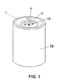
- Imitation candle body 10 is a squat element, configured to resemble a self supporting candle which has burned down by the center.
- Imitation candle body 10 which can be fabricated in wax or translucent plastic, contains an internal light source positioned within the imitation candle body so as to illuminate the candle body with a diffuse, flickering glow that simulates the appearance of a lit candle.
- a light pipe 12 extends upwardly from a central depressed section 14 in the upper surface 19 of imitation candle body 10.
- a buried end of a light pipe 12 is positioned in sufficiently close proximity to the internal light source to capture a portion of the light emitted by the light source sufficient to generate a bright point source of light at an exposed tip end 18 at the opposite end of the light pipe.
- This opposite, exposed end of the light pipe 12 extends from candle body 10 at a location where a candle wick would normally be positioned.
- the extreme tip end 18 of light pipe 12 is roughened or faceted to diffuse the captured light and create the visible bright point source of light.
- a dark colored sleeve 16 extends from tip end 18 at least to the depressed surface 14 and covers the all but the tip end 18 of the exposed portion of light pipe 12 to simulate the look of a real, previously burned wick. Emission of light from the internal light source is indicated at letter "A" by phantom lines.
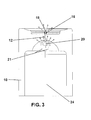
- Fig. 2 shows a cross-sectional view of the imitation candle body 10 shown in Figure 1 illustrating a possible internal configuration thereof.
- a cavity 24 within the lower portion of imitation candle body 10 allows space for the installation of an electronics module (not shown) that provides the power source, switch and circuitry needed to drive the internal light source 20.
- Internal light source 20 is preferably a super bright light emitting diode (LED) as described in United States Patent 6,616,308 but could be an incandescent source.
- an electronics module may include on/off timers, daylight sensors and a flicker energization circuit to cause the light source 20 to flicker after the fashion on an unstable candle flame.
- Light pipe 12 is disposed with one end 15 located near to and open with respect to light source 20. When light source 20 is illuminated light pipe 12 captures a small portion of the light emitted thereby.
- Light pipe 12 is preferably constructed using a single fiber optic cable with a diameter similar to a candle wick. Alternatively light pipe 12 could be a small bundle of smaller fiber optic filaments.
- the light captured by light pipe 12 from light source 20 is directed to the opposite end of the light pipe where it strikes a light diffusing tip 18.
- Light diffusing tip 18 is preferably made by roughening or faceting the end of the light pipe so that it scatters light over a broad viewing angle to form a near point source of bright light. Still other alternate schemes may also be used to diffuse the light when it reaches the exposed end of the light pipe 12.
- Dark colored, opaque sleeve 16 surrounds the expose portion of light pipe 12 excluding the light diffusing tip end 18 and serves to disguise the light pipe 12 and give it the appearance of a real wick which has burned down. Alternatives to the sleeve 16 could be used to disguise the light pipe 12 as a wick, but care must be taken not to interfere with the light transmitting properties of the light pipe 12.
- An opaque barrier 22 is disposed over cavity 24 and under light source 20. Opaque barrier 22 controls illumination levels from top to bottom of the imitation candle body 10, limiting light emission to the upper portion of the body.
- Fig. 3 shows an alternative embodiment for the internal configuration of imitation candle body 10.
- An array of LED's 21 are disposed around light source (LED) 20 within imitation candle body 10.
- the primary role of the additional LED's 21 is to more fully illuminate imitation candle body 10 thus allowing more of the light from main light source 20 to be captured by the light pipe 12 increasing the intensity of light emitted at the light diffusing tip end 18.
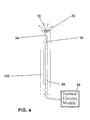
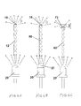
- Fig. 4 shows an embodiment of the invention in a taper style candle body 100.
- Taper style candle body 100 has a small channel 26 running nearly the length of the body from near its top out through the bottom of the body is used to allow connection of the light source 28 to an external circuit 30. External circuit 30 would typically be hidden in a candle pedestal. Alternatively the electronics could be miniaturized to fit in the imitation candle body at some expense.
- the upper end of taper style candle body 100 is closed and forms a depressed surface 32 with a fiber optic light pipe 34 passing through the depressed surface from a lower end adjacent light source 28 to an exposed tip end 38. Again, most of the exposed portion of light pipe 34 is enclosed in a darkened, opaque sleeve 36, except for the light diffusing tip end 38.
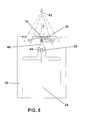
- Fig. 5 shows an alternative embodiment of the invention wherein the light pipe 40 is designed to capture a large portion of the light emanating from the light source 20.
- the end of light pipe 40 adjacent light source is bulbous, and extends around the light source forming a cylindrical receptacle 44 in which LED 20 is disposed.
- An external LED 42 located above the imitation candle body 10 and typically hidden within a fixture that contains the candle, is used to illuminate the imitation candle body from above.
- Figs. 6A-C shows detailed views of three possible implementations of the light source 20 and various light pipes.
- Fig. 6A shows a simple light pipe 12 one end of which has been scratched and roughened to form a light diffusing tip 18. A portion of the light emanating from the light source 20 is captured by the light pipe 12 and directed to the light diffusing tip 18 where it is scattered to form a bright point source of light.
- Fig. 6B shows a light pipe 50 which has been molded as an integral part of the epoxy body 27 that encapsulates the LED 20 and operates as an optical coupling element between the LED and the light pipe.
- Fig. 6A shows a simple light pipe 12 one end of which has been scratched and roughened to form a light diffusing tip 18. A portion of the light emanating from the light source 20 is captured by the light pipe 12 and directed to the light diffusing tip 18 where it is scattered to form a bright point source of light.
- Fig. 6B shows a light pipe 50 which has been molded as an integral part of
- 6C shows an alternate construction that using a light pipe 60 that is polished on both ends and uses a separate diffuser 70 to redirect the light coming from the exposed end 80 of the light pipe 60.
- all three light pipes 12, 50 and 60 light is illustrated as being transmitted through the pipes, being reflected inwardly by the surface of the pipe until encountering an irregular, light diffusing, terminating end.
- the letter D illustrates scattering of the light.
- the invention provides an imitation candle giving a realistic illusion of supporting an exposed flame while retaining flickering, illuminated body.
Landscapes
- Engineering & Computer Science (AREA)
- General Engineering & Computer Science (AREA)
- Physics & Mathematics (AREA)
- General Physics & Mathematics (AREA)
- Optics & Photonics (AREA)
- Non-Portable Lighting Devices Or Systems Thereof (AREA)
Applications Claiming Priority (3)
| Application Number | Priority Date | Filing Date | Title |
|---|---|---|---|
| US11/053,397 US7360935B2 (en) | 2005-03-31 | 2005-03-31 | Imitation candle with simulated lighted wick |
| EP06748667A EP1869360B1 (fr) | 2005-03-31 | 2006-03-24 | Bougie d' imitation avec fausse meche allumee |
| EP11188478.9A EP2418418B1 (fr) | 2005-03-31 | 2006-03-24 | Bougie d'imitation avec une fausse mèche éclairante |
Related Parent Applications (2)
| Application Number | Title | Priority Date | Filing Date |
|---|---|---|---|
| EP11188478.9A Division EP2418418B1 (fr) | 2005-03-31 | 2006-03-24 | Bougie d'imitation avec une fausse mèche éclairante |
| EP06748667A Division EP1869360B1 (fr) | 2005-03-31 | 2006-03-24 | Bougie d' imitation avec fausse meche allumee |
Publications (2)
| Publication Number | Publication Date |
|---|---|
| EP2857738A2 true EP2857738A2 (fr) | 2015-04-08 |
| EP2857738A3 EP2857738A3 (fr) | 2016-03-09 |
Family
ID=36576956
Family Applications (3)
| Application Number | Title | Priority Date | Filing Date |
|---|---|---|---|
| EP11188478.9A Expired - Lifetime EP2418418B1 (fr) | 2005-03-31 | 2006-03-24 | Bougie d'imitation avec une fausse mèche éclairante |
| EP14200595.8A Withdrawn EP2857738A3 (fr) | 2005-03-31 | 2006-03-24 | Bougie d'imitation avec fausse mèche allumée |
| EP06748667A Expired - Lifetime EP1869360B1 (fr) | 2005-03-31 | 2006-03-24 | Bougie d' imitation avec fausse meche allumee |
Family Applications Before (1)
| Application Number | Title | Priority Date | Filing Date |
|---|---|---|---|
| EP11188478.9A Expired - Lifetime EP2418418B1 (fr) | 2005-03-31 | 2006-03-24 | Bougie d'imitation avec une fausse mèche éclairante |
Family Applications After (1)
| Application Number | Title | Priority Date | Filing Date |
|---|---|---|---|
| EP06748667A Expired - Lifetime EP1869360B1 (fr) | 2005-03-31 | 2006-03-24 | Bougie d' imitation avec fausse meche allumee |
Country Status (5)
| Country | Link |
|---|---|
| US (1) | US7360935B2 (fr) |
| EP (3) | EP2418418B1 (fr) |
| AT (1) | ATE533992T1 (fr) |
| CA (1) | CA2604497C (fr) |
| WO (1) | WO2006104898A1 (fr) |
Families Citing this family (57)
| Publication number | Priority date | Publication date | Assignee | Title |
|---|---|---|---|---|
| US7824627B2 (en) | 2004-02-03 | 2010-11-02 | S.C. Johnson & Son, Inc. | Active material and light emitting device |
| US7538473B2 (en) * | 2004-02-03 | 2009-05-26 | S.C. Johnson & Son, Inc. | Drive circuits and methods for ultrasonic piezoelectric actuators |
| US7723899B2 (en) * | 2004-02-03 | 2010-05-25 | S.C. Johnson & Son, Inc. | Active material and light emitting device |
| WO2007041574A1 (fr) * | 2005-10-03 | 2007-04-12 | S. C. Johnson & Son, Inc. | Appareil lumineux |
| ES2536412T3 (es) * | 2008-04-15 | 2015-05-25 | D. Swarovski Kg | Dispositivo luminiscente |
| US8342712B2 (en) | 2008-09-30 | 2013-01-01 | Disney Enterprises, Inc. | Kinetic flame device |
| US8132936B2 (en) * | 2008-09-30 | 2012-03-13 | Disney Enterprises, Inc. | Kinetic flame device |
| US8210708B2 (en) | 2008-11-18 | 2012-07-03 | Smart Candle, Llc | Induction rechargeable electronic candle system |
| US20100207538A1 (en) * | 2009-02-13 | 2010-08-19 | Nature Candle Corporation | Electronic candle structure |
| USD613898S1 (en) | 2009-03-20 | 2010-04-13 | S.C. Johnson & Son, Inc. | Decorative candle holder |
| US20100254155A1 (en) * | 2009-04-07 | 2010-10-07 | Rensselaer Polytechnic Institute | Simulated Candle and Method For Simulating a Candle |
| US8215789B2 (en) * | 2009-05-14 | 2012-07-10 | Mary Elle Fashions | Light-emitting apparatus |
| CN201547593U (zh) * | 2009-06-05 | 2010-08-11 | 北京汇冠新技术股份有限公司 | 一种用于触摸屏的光源 |
| USD619274S1 (en) | 2009-10-16 | 2010-07-06 | Osram Sylvania Inc. | Candelabra for LED candle lights |
| US8482186B2 (en) * | 2010-05-03 | 2013-07-09 | Young Lighting Technology Inc. | Lighting device |
| CN101865413B (zh) | 2010-06-28 | 2012-08-01 | 李晓锋 | 模拟真火的电子发光装置及其模拟真火的方法 |
| US9371973B2 (en) | 2010-06-28 | 2016-06-21 | Shenzhen Liown Electronics Company Ltd. | Electronic lighting device and method for manufacturing same |
| CN102418856A (zh) * | 2011-06-01 | 2012-04-18 | 南通亚泰蜡业工艺品有限公司 | 一种电子蜡烛 |
| CN102418903A (zh) * | 2011-06-01 | 2012-04-18 | 南通亚泰蜡业工艺品有限公司 | 电子蜡烛 |
| DK2570714T3 (en) * | 2011-09-16 | 2016-08-22 | Nantong Ya Tai Candle Arts & Crafts Co Ltd | Electronic candles |
| CN102287762A (zh) * | 2011-09-16 | 2011-12-21 | 南通亚泰蜡业工艺品有限公司 | 一种电子蜡烛 |
| DE202011106610U1 (de) * | 2011-09-27 | 2011-11-22 | Gms Gmbh | Elektrische Kerze |
| US9068706B2 (en) | 2012-03-07 | 2015-06-30 | Winvic Sales Inc. | Electronic luminary device with simulated flame |
| CN102853368A (zh) * | 2012-03-30 | 2013-01-02 | 南通亚泰蜡业工艺品有限公司 | 摇摆电子蜡烛 |
| US9341342B2 (en) | 2012-10-09 | 2016-05-17 | Young March Co., Ltd. | Colored lens LED simulated wick flameless candle |
| US20140211499A1 (en) * | 2013-01-25 | 2014-07-31 | Peter Sui Lun Fong | Device with simulated flame |
| US9572236B2 (en) | 2013-01-30 | 2017-02-14 | Luminara Worldwide, Llc | Systems and methods for controlling a plurality of electric candles |
| US9360181B2 (en) | 2013-03-15 | 2016-06-07 | Xiaofeng Li | Electronic flameless candle |
| US9371972B2 (en) * | 2013-03-15 | 2016-06-21 | Xiaofeng Li | Electronic flameless candle |
| USD729424S1 (en) * | 2013-05-20 | 2015-05-12 | Xiaofeng Li | Electronic lighting device |
| USD706484S1 (en) * | 2013-09-27 | 2014-06-03 | Nga Tik Poon | LED candle wick |
| DE202013105564U1 (de) | 2013-12-06 | 2014-01-16 | Nantong Ya Tai Candle Arts & Crafts Co., Ltd. | Elektronische Kerze mit farbigem Licht |
| CN203940345U (zh) | 2014-06-24 | 2014-11-12 | 李晓锋 | 一种模拟真火发光的照明装置 |
| CN203927447U (zh) * | 2014-07-10 | 2014-11-05 | 深圳市亚美特科技有限公司 | 一种无光源连接导线的电子蜡烛 |
| USD739090S1 (en) * | 2014-12-16 | 2015-09-15 | Banks Outdoors Corporation | Animal watering tank |
| USD739091S1 (en) * | 2014-12-16 | 2015-09-15 | Banks Outdoors Corporation | Stump watering tank |
| US9401468B2 (en) | 2014-12-24 | 2016-07-26 | GE Lighting Solutions, LLC | Lamp with LED chips cooled by a phase transformation loop |
| EP3307321A4 (fr) | 2015-08-26 | 2019-04-17 | Bison Therapeutics Inc. | Plate-forme d'anticorps multi-spécifiques et procédés associés |
| KR102427644B1 (ko) * | 2015-11-16 | 2022-08-02 | 삼성전자주식회사 | 광원 모듈, 광원 모듈의 제조방법 및 이를 포함하는 디스플레이 장치 |
| US9709230B2 (en) | 2015-12-14 | 2017-07-18 | Luminara Worldwide, Llc | Electric candle having flickering effect |
| WO2017132224A1 (fr) | 2016-01-25 | 2017-08-03 | Lowe's Companies, Inc. | Simulateur de flamme à faisceau lumineux mobile |
| US9739432B2 (en) | 2016-01-27 | 2017-08-22 | Xiaofeng Li | Imitation candle and flame simulation assembly thereof |
| US9605824B1 (en) | 2016-05-03 | 2017-03-28 | Xiaofeng Li | Imitation candle device with enhanced control features |
| CN107514597A (zh) | 2016-06-17 | 2017-12-26 | 李晓锋 | 用于远程控制仿真蜡烛装置的系统和方法 |
| CN107543113B (zh) | 2016-06-27 | 2020-07-28 | 李晓锋 | 香味电子蜡烛装置 |
| WO2018035841A1 (fr) * | 2016-08-26 | 2018-03-01 | Xiaofeng Li | Bougie artificielle et ensemble de simulation de flamme présentant un éclairage multicolore |
| CN206410036U (zh) | 2016-11-16 | 2017-08-15 | 谭志明 | 电子蜡烛 |
| CA3065757A1 (fr) | 2017-03-28 | 2018-10-04 | MerchSource, LLC | Bougie electronique sans flamme |
| CN108653785B (zh) | 2017-04-01 | 2024-11-29 | 深圳市里阳电子有限公司 | 一种香味生成装置、香薰装置及电子蜡烛 |
| US10393332B2 (en) | 2017-04-20 | 2019-08-27 | L & L Candle Company, LLC | Electric candle having flickering effect |
| CN109140367B (zh) | 2017-06-17 | 2025-06-27 | 深圳市里阳电子有限公司 | 电子香薰蜡烛及香料容器 |
| CN207146265U (zh) * | 2017-07-31 | 2018-03-27 | 宁波隆升家居饰品有限公司 | 一种新型触控式电子蜡烛灯 |
| US10352517B2 (en) | 2017-09-07 | 2019-07-16 | Sterno Home Inc. | Artificial candle with moveable projection screen position |
| US11506351B1 (en) * | 2022-03-23 | 2022-11-22 | Chang Zhou Man Mei Industrial Co., Ltd. | Highly simulated electronic candle |
| USD1032918S1 (en) * | 2022-09-20 | 2024-06-25 | Qiong DU | Electronic candle |
| USD1084467S1 (en) * | 2023-02-01 | 2025-07-15 | deluxe holding ApS | LED candle |
| CN223216143U (zh) * | 2024-08-20 | 2025-08-12 | 厦门智慧灯工贸有限公司 | 电子蜡烛的仿真烛火结构 |
Citations (1)
| Publication number | Priority date | Publication date | Assignee | Title |
|---|---|---|---|---|
| US6616308B2 (en) | 2001-08-14 | 2003-09-09 | Jenesis International, Inc. | Imitation candle |
Family Cites Families (18)
| Publication number | Priority date | Publication date | Assignee | Title |
|---|---|---|---|---|
| US1351562A (en) * | 1919-09-10 | 1920-08-31 | J B Wadman | Illusion apparatus |
| US2080259A (en) * | 1936-08-06 | 1937-05-11 | Jr John Frei | Light transmitting means |
| US2435811A (en) * | 1945-03-30 | 1948-02-10 | Harry E Waters | Artificial candle |
| US3681588A (en) * | 1970-11-16 | 1972-08-01 | Carolina Enterprises | Candelabrum and light transmitting means therefor |
| US3749904A (en) | 1971-02-25 | 1973-07-31 | R Graff | Illuminated wax form and method of making same |
| GB2322185A (en) * | 1997-02-15 | 1998-08-19 | Raymond Walter Harcombe | Battery powered Christmas tree decoration shaped like a candle |
| US6074199A (en) * | 1998-02-10 | 2000-06-13 | Song; Jin | Sound producing candle |
| US6504648B2 (en) * | 2000-09-21 | 2003-01-07 | George Mauro | Compensation mechanism for component and assembly deviation in a component precision positioning stage |
| US20020093834A1 (en) * | 2001-01-12 | 2002-07-18 | Chun-Chien Yu | Light-effect producing candle |
| US20020110319A1 (en) | 2001-02-14 | 2002-08-15 | Yin-Su Chung | Optical fiber having decorative effect |
| GB2380539B (en) | 2001-09-29 | 2003-12-24 | Paul Dayan Metcalfe | Illuminated paving slab |
| US7229201B2 (en) | 2003-03-26 | 2007-06-12 | Optim Inc. | Compact, high-efficiency, high-power solid state light source using a single solid state light-emitting device |
| CN2637894Y (zh) * | 2003-11-25 | 2004-09-01 | 李晓锋 | 闪光彩虹蜡烛 |
| US7063526B2 (en) * | 2004-02-13 | 2006-06-20 | Yoon Ho Ham | Refillable melody candle |
| US20050239009A1 (en) * | 2004-04-22 | 2005-10-27 | Keith Holmburg | Sound-producing candle assembly |
| US7093961B2 (en) | 2004-05-12 | 2006-08-22 | Jenesis International, Inc. | Lantern with imitation flame source |
| US20060046220A1 (en) * | 2004-09-01 | 2006-03-02 | Hui Lin | Photo-controlled electronic music candle |
| US7121686B1 (en) * | 2005-11-03 | 2006-10-17 | Paul Chu | Candle light-diversifying device |
-
2005
- 2005-03-31 US US11/053,397 patent/US7360935B2/en not_active Expired - Lifetime
-
2006
- 2006-03-24 AT AT06748667T patent/ATE533992T1/de active
- 2006-03-24 EP EP11188478.9A patent/EP2418418B1/fr not_active Expired - Lifetime
- 2006-03-24 EP EP14200595.8A patent/EP2857738A3/fr not_active Withdrawn
- 2006-03-24 CA CA2604497A patent/CA2604497C/fr not_active Expired - Fee Related
- 2006-03-24 WO PCT/US2006/010818 patent/WO2006104898A1/fr not_active Ceased
- 2006-03-24 EP EP06748667A patent/EP1869360B1/fr not_active Expired - Lifetime
Patent Citations (1)
| Publication number | Priority date | Publication date | Assignee | Title |
|---|---|---|---|---|
| US6616308B2 (en) | 2001-08-14 | 2003-09-09 | Jenesis International, Inc. | Imitation candle |
Also Published As
| Publication number | Publication date |
|---|---|
| EP1869360A1 (fr) | 2007-12-26 |
| US20080074875A1 (en) | 2008-03-27 |
| EP2857738A3 (fr) | 2016-03-09 |
| US7360935B2 (en) | 2008-04-22 |
| EP2418418A3 (fr) | 2012-10-31 |
| CA2604497A1 (fr) | 2006-10-05 |
| EP2418418B1 (fr) | 2014-12-31 |
| EP1869360B1 (fr) | 2011-11-16 |
| ATE533992T1 (de) | 2011-12-15 |
| CA2604497C (fr) | 2012-04-10 |
| EP2418418A2 (fr) | 2012-02-15 |
| WO2006104898A1 (fr) | 2006-10-05 |
Similar Documents
| Publication | Publication Date | Title |
|---|---|---|
| EP2418418B1 (fr) | Bougie d'imitation avec une fausse mèche éclairante | |
| US7093961B2 (en) | Lantern with imitation flame source | |
| US7828462B2 (en) | Imitation candle with simulated lighted wick using external light source | |
| EP1419345B1 (fr) | Bougie artificielle | |
| US20140035483A1 (en) | Two ended faux candle | |
| US6808297B2 (en) | Decorative candle lamp | |
| US6575613B2 (en) | Portable special effects illumination device | |
| US20080304289A1 (en) | LED night light with more than 1 optics means | |
| US7611261B2 (en) | Decorating with a lighted device | |
| US10436396B2 (en) | Artificial candle and its light bulb | |
| JP2016143598A (ja) | 芳香器機能付きキャンドルライト | |
| CN210035151U (zh) | 一种全息影像结构的投影装置 | |
| JP3249181U (ja) | ランタン型照明器具 | |
| CN219414537U (zh) | 一种通过透孔出光方式实现具有火焰仿真效果的灯具 | |
| CA2605301C (fr) | Bougie artificielle | |
| JP3029834U (ja) | 仏壇の内部照明器具 | |
| EP1500338A1 (fr) | Fleur artificielle avec dispositif d'illumination pour usage intérieur et extérieur | |
| JP2006066230A (ja) | ライティング装置 | |
| HK1143198B (en) | Imitation candle |
Legal Events
| Date | Code | Title | Description |
|---|---|---|---|
| PUAI | Public reference made under article 153(3) epc to a published international application that has entered the european phase |
Free format text: ORIGINAL CODE: 0009012 |
|
| 17P | Request for examination filed |
Effective date: 20141230 |
|
| AC | Divisional application: reference to earlier application |
Ref document number: 2418418 Country of ref document: EP Kind code of ref document: P Ref document number: 1869360 Country of ref document: EP Kind code of ref document: P |
|
| AK | Designated contracting states |
Kind code of ref document: A2 Designated state(s): AT BE BG CH CY CZ DE DK EE ES FI FR GB GR HU IE IS IT LI LT LU LV MC NL PL PT RO SE SI SK TR |
|
| PUAL | Search report despatched |
Free format text: ORIGINAL CODE: 0009013 |
|
| AK | Designated contracting states |
Kind code of ref document: A3 Designated state(s): AT BE BG CH CY CZ DE DK EE ES FI FR GB GR HU IE IS IT LI LT LU LV MC NL PL PT RO SE SI SK TR |
|
| R17P | Request for examination filed (corrected) |
Effective date: 20160909 |
|
| RBV | Designated contracting states (corrected) |
Designated state(s): AT BE BG CH CY CZ DE DK EE ES FI FR GB GR HU IE IS IT LI LT LU LV MC NL PL PT RO SE SI SK TR |
|
| RIN1 | Information on inventor provided before grant (corrected) |
Inventor name: MCCAVIT, KIM I. Inventor name: BENTLEY, ROGER D. Inventor name: JENSEN, BRADFORD B. |
|
| RAP1 | Party data changed (applicant data changed or rights of an application transferred) |
Owner name: NII NORTHERN INTERNATIONAL INC. |
|
| RIC1 | Information provided on ipc code assigned before grant |
Ipc: F21Y 115/10 20160101ALI20180130BHEP Ipc: F21V 8/00 20060101ALI20180130BHEP Ipc: F21S 6/00 20060101AFI20180130BHEP Ipc: F21S 10/04 20060101ALI20180130BHEP Ipc: F21W 121/00 20060101ALI20180130BHEP |
|
| GRAP | Despatch of communication of intention to grant a patent |
Free format text: ORIGINAL CODE: EPIDOSNIGR1 |
|
| STAA | Information on the status of an ep patent application or granted ep patent |
Free format text: STATUS: GRANT OF PATENT IS INTENDED |
|
| RAP1 | Party data changed (applicant data changed or rights of an application transferred) |
Owner name: STERNO HOME INC. |
|
| INTG | Intention to grant announced |
Effective date: 20180327 |
|
| STAA | Information on the status of an ep patent application or granted ep patent |
Free format text: STATUS: THE APPLICATION IS DEEMED TO BE WITHDRAWN |
|
| 18D | Application deemed to be withdrawn |
Effective date: 20180807 |
|
| RIC1 | Information provided on ipc code assigned before grant |
Ipc: F21W 121/00 20060101ALI20180130BHEP Ipc: F21Y 115/10 20160101ALI20180130BHEP Ipc: F21S 6/00 20060101AFI20180130BHEP Ipc: F21S 10/04 20060101ALI20180130BHEP Ipc: F21V 8/00 20060101ALI20180130BHEP |