EP2857745A2 - Système de refroidissement de phare à DEL pour automobile - Google Patents
Système de refroidissement de phare à DEL pour automobile Download PDFInfo
- Publication number
- EP2857745A2 EP2857745A2 EP14187452.9A EP14187452A EP2857745A2 EP 2857745 A2 EP2857745 A2 EP 2857745A2 EP 14187452 A EP14187452 A EP 14187452A EP 2857745 A2 EP2857745 A2 EP 2857745A2
- Authority
- EP
- European Patent Office
- Prior art keywords
- fluid
- evaporator
- radiator
- light source
- lighting assembly
- Prior art date
- Legal status (The legal status is an assumption and is not a legal conclusion. Google has not performed a legal analysis and makes no representation as to the accuracy of the status listed.)
- Granted
Links
Images


Classifications
-
- F—MECHANICAL ENGINEERING; LIGHTING; HEATING; WEAPONS; BLASTING
- F21—LIGHTING
- F21K—NON-ELECTRIC LIGHT SOURCES USING LUMINESCENCE; LIGHT SOURCES USING ELECTROCHEMILUMINESCENCE; LIGHT SOURCES USING CHARGES OF COMBUSTIBLE MATERIAL; LIGHT SOURCES USING SEMICONDUCTOR DEVICES AS LIGHT-GENERATING ELEMENTS; LIGHT SOURCES NOT OTHERWISE PROVIDED FOR
- F21K9/00—Light sources using semiconductor devices as light-generating elements, e.g. using light-emitting diodes [LED] or lasers
- F21K9/20—Light sources comprising attachment means
-
- F—MECHANICAL ENGINEERING; LIGHTING; HEATING; WEAPONS; BLASTING
- F21—LIGHTING
- F21S—NON-PORTABLE LIGHTING DEVICES; SYSTEMS THEREOF; VEHICLE LIGHTING DEVICES SPECIALLY ADAPTED FOR VEHICLE EXTERIORS
- F21S41/00—Illuminating devices specially adapted for vehicle exteriors, e.g. headlamps
- F21S41/10—Illuminating devices specially adapted for vehicle exteriors, e.g. headlamps characterised by the light source
- F21S41/14—Illuminating devices specially adapted for vehicle exteriors, e.g. headlamps characterised by the light source characterised by the type of light source
- F21S41/141—Light emitting diodes [LED]
- F21S41/151—Light emitting diodes [LED] arranged in one or more lines
- F21S41/153—Light emitting diodes [LED] arranged in one or more lines arranged in a matrix
-
- F—MECHANICAL ENGINEERING; LIGHTING; HEATING; WEAPONS; BLASTING
- F21—LIGHTING
- F21S—NON-PORTABLE LIGHTING DEVICES; SYSTEMS THEREOF; VEHICLE LIGHTING DEVICES SPECIALLY ADAPTED FOR VEHICLE EXTERIORS
- F21S45/00—Arrangements within vehicle lighting devices specially adapted for vehicle exteriors, for purposes other than emission or distribution of light
- F21S45/40—Cooling of lighting devices
- F21S45/47—Passive cooling, e.g. using fins, thermal conductive elements or openings
-
- F—MECHANICAL ENGINEERING; LIGHTING; HEATING; WEAPONS; BLASTING
- F21—LIGHTING
- F21V—FUNCTIONAL FEATURES OR DETAILS OF LIGHTING DEVICES OR SYSTEMS THEREOF; STRUCTURAL COMBINATIONS OF LIGHTING DEVICES WITH OTHER ARTICLES, NOT OTHERWISE PROVIDED FOR
- F21V29/00—Protecting lighting devices from thermal damage; Cooling or heating arrangements specially adapted for lighting devices or systems
- F21V29/50—Cooling arrangements
- F21V29/51—Cooling arrangements using condensation or evaporation of a fluid, e.g. heat pipes
-
- F—MECHANICAL ENGINEERING; LIGHTING; HEATING; WEAPONS; BLASTING
- F21—LIGHTING
- F21S—NON-PORTABLE LIGHTING DEVICES; SYSTEMS THEREOF; VEHICLE LIGHTING DEVICES SPECIALLY ADAPTED FOR VEHICLE EXTERIORS
- F21S8/00—Lighting devices intended for fixed installation
- F21S8/04—Lighting devices intended for fixed installation intended only for mounting on a ceiling or the like overhead structures
-
- F—MECHANICAL ENGINEERING; LIGHTING; HEATING; WEAPONS; BLASTING
- F21—LIGHTING
- F21Y—INDEXING SCHEME ASSOCIATED WITH SUBCLASSES F21K, F21L, F21S and F21V, RELATING TO THE FORM OR THE KIND OF THE LIGHT SOURCES OR OF THE COLOUR OF THE LIGHT EMITTED
- F21Y2115/00—Light-generating elements of semiconductor light sources
- F21Y2115/10—Light-emitting diodes [LED]
Definitions
- provisional application serial number 61/886,032 filed October 2, 2013 , and entitled "Automotive Led Highlight Cooling System", by these same inventors.
- This application incorporates U.S. patent application serial number 13/921,067 , U.S. provisional application serial number 61/665,179 , U.S. provisional application serial number 61/673,660 and U.S. provisional application serial number 61/886,032 , in their entireties by reference.
- the present invention is generally directed to the field of light emitting diode (LED) lighting. More specifically, the present invention is directed to a cooling system for a LED device.
- LED light emitting diode
- a light-emitting diode is a semiconductor light source. LEDs are increasingly being used in a wide variety of lighting applications. LEDs continue growing in popularity due in part to their efficiency and extended lifetimes. In some high power applications, such as LEDs designed to operate at a few hundred watts, a lot of heat is generated, which needs to be dissipated.
- a lighting assembly includes a cooling system configured to enable the dissipation of a large amount of energy in the form of heaf generated by a light source. Heat is dissipated without heating surrounding components, such as power supply units and device electronics.
- the cooling system is configured as a gravity feed system that does not require a powered fluid pump.
- the cooling loop is configured as a thermal siphon that uses a boiling fluid to transport heat between the evaporator and the radiator.
- the evaporator also functions as a device chassis, which reduces the overall part count.
- the light source is a plurality of LEDs mounted on a printed circuit board (PCB).
- the PCB is aligned and mounted vertically onto the evaporator.
- the evaporator is configured to enable the vertical alignment of the PCB and to cool the PCB while in this vertical alignment. The vertical alignment of the PCB enables horizontal projection of light emitted by the LEDs, such as in an automotive headlight application.
- a lighting assembly for cooling a light source includes a light source, an evaporator and a cooling loop.
- the light source has a vertically aligned thermal exchange surface.
- the evaporator has a side thermal exchange surface thermally coupled to the vertically aligned thermal exchange surface of the light source.
- the evaporator also has a reservoir and a fluid within the reservoir. The evaporator is configured such that at least a portion of the fluid is vaporized by heat transferred from the light source.
- the cooling loop is coupled to the evaporator.
- the cooling loop includes a transfer pipe coupled to the evaporator, a radiator coupled to the transfer pipe, and a return pipe coupled to the radiator and to the evaporator.
- the radiator is configured to receive vapor from the evaporator via the transfer pipe and to condense the vapor, and the radiator and the return pipe are configured to gravity feed fluid to the evaporator.
- the radiator includes a first end coupled to the transfer pipe and a second end, and the radiator is aligned along a non-horizontal plane with the first end positioned higher than the second end.
- the return pipe includes a first end coupled to the second end of the radiator and a second end coupled to the evaporator, the return pipe is configured and aligned having the first end of the return pipe positioned higher than the second end of the return pipe.
- the transfer pipe is configured to be vertically ascending.
- the radiator is a finned radiator.
- the transfer pipe is a finned pipe.
- the fluid is a fluid mixture having at least a first fluid and a second fluid having a higher boiling temperature than the first fluid, wherein the first fluid includes the portion of the fluid vaporized by heat transferred from the light source.
- the evaporator and the fluid mixture are configured such that when the portion of the fluid is vaporized by heat transferred from the light source a boiling fluid is formed, further wherein the evaporator and the transfer pipe are configured such that the boiling fluid is siphoned from the evaporator to the radiator.
- the light source includes a plurality of light emitting diodes.
- the light source also includes a printed circuit board coupled to the plurality of light emitting diodes.
- the light source is aligned to emit a horizontal projection of light.
- the lighting assembly includes a light source, an evaporator, a transfer pipe, a radiator and a return pipe.
- the light source has a vertically aligned thermal exchange surface.
- the evaporator has a side thermal exchange surface thermally coupled to the vertically aligned thermal exchange surface of the light source.
- the evaporator includes a reservoir and a fluid within the reservoir. The evaporator is configured such that at least a portion of the fluid is vaporized by heat transferred from the light source.
- the transfer pipe is coupled to the evaporator such that vapor formed in the evaporator rises through the transfer pipe.
- the radiator is coupled to the transfer pipe.
- the radiator includes a first end coupled to the transfer pipe and a second end.
- the radiator is aligned along a non-horizontal plane with the first end positioned higher than the second end.
- the radiator is configured such that vapor received from the transfer pipe is condensed to fluid and the fluid is gravity fed to the second end.
- the return pipe is coupled to the radiator.
- the return pipe includes a first end coupled to the second end of the radiator and a second end coupled to the evaporator.
- the return pipe is configured and aligned having the first end of the return pipe positioned higher than the second end of the return pipe such that fluid output from the second end of the radiator is gravity fed to the evaporator.
- the transfer pipe is configured to be vertically ascending.
- the radiator is a finned radiator.
- the transfer pipe is a finned pipe.
- the fluid is a fluid mixture having at least a first fluid and a second fluid having a higher boiling temperature than the first fluid, wherein the first fluid includes the portion of the fluid vaporized by heat transferred from the light source.
- the evaporator and the fluid mixture are configured such that when the portion of the fluid is vaporized by heat transferred from the light source a boiling fluid is formed, further wherein the evaporator and the transfer pipe are configured such that the boiling fluid is siphoned from the evaporator to the radiator.
- the light source includes a plurality of light emitting diodes.
- the light source also includes a printed circuit board coupled to the plurality of light emitting diodes.
- the light source is aligned to emit a horizontal projection of light.
- Embodiments of the present application are directed to a lighting assembly. Those of ordinary skill in the art will realize that the following detailed description of the lighting assembly is illustrative only and is not intended to be in any way limiting. Other embodiments of the lighting assembly will readily suggest themselves to such skilled persons having the benefit of this disclosure.
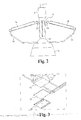
- Figure 1 illustrates a perspective view of a lighting assembly according to an embodiment.
- the lighting assembly includes a light source, a cooling system, one or more power supply units, device electronics, and a mounting structure.
- the cooling system includes one or more cooling loops, each cooling loop including an evaporator, a vertically ascending pipe, a radiator and a return pipe.
- the exemplary cooling system shown in Figure 1 includes two cooling loops, each cooling loop shares a comnon evaporator 14.
- Figure 2 illustrates a side view of the lighting assembly 2 of Figure 1 .
- a first cooling loop includes the evaporator 14, a vertically ascending pipe 16, a radiator 18, and a return pipe 20.
- a second cooling loop includes the evaporator 14, a vertically ascending pipe 26, a radiator 28 and a return pipe 30.
- Figures 1 and 2 also show an optional reflector 12.
- the light source is positioned within the reflector 12.
- the first cooling loop and the second cooling loop are each closed loop.
- two closed loop cooling systems are shown in the lighting assembly of Figures 1 and 2 , it is understood that a lighting assembly can be configured to include a single closed loop cooling system or three or more closed loop cooling systems.
- the lighting assembly includes a mounting structure 10 coupled to the evaporator 14 and to device electronics 8. In this exemplary configuration, the lighting assembly includes two power supplies 6.
- the power supplies 6 can be mounted to the mounting structure 10, a housing of the device electronics 8, the evaporator 14, the pipes 16 and 26 or some combination thereof.
- An external mounting base 7 is coupled to the housing of the device electronics 8.
- the external mounting base 7 is used to mount the lighting assembly.
- the external mounting base 7 is configured to receive a conduit, which in turn is mounted to an external
- the cooling system is configured to enable the dissipation of a large amount of energy in the form of heat without heating surrounding components, such as the one or more power supply units and device electronics.
- the cooling loop is configured as a thermal siphon that uses a boiling fluid to transport heat between the evaporator and the radiators.
- the evaporator also functions as a device chassis, which reduces the overall part count.
- the light source is a plurality of LEDs. LEDs have a well defined thermal performance and therefore operate properly within a defined temperature range.
- the cooling system is designed to maintain the LED temperatures within the defined temperature range.
- the one or more power supply units are arranged such that heat generated by the one or more power supply units does not negatively impact the thermal performance of the LED light source.
- the evaporator 14 is a fluid-based heat exchanger that conceptually functions as a boiling unit.
- the evaporator 14 includes a fluid reservoir that is filled, or partially filled, with a fluid or fluid mixture, herein referred to collectively as a fluid.
- the evaporator 14 is thermally coupled to the light source such that heat generated by the light source is transferred to the fluid within the evaporator 14. The heat causes fluid in the evaporator 14 to evaporate. The resulting vapor rises through the vertically ascending pipes 16, 26 to the radiators 18, 28.
- each pipe 16, 26 includes a first portion that extends straight up from the evaporator 14 and a second portion that bends at an angle from completely vertical, but not horizontal, which is coupled to the radiator 18, 28. In some embodiments, the angle of the second portion is 30 to 60 degrees relative to vertical or the first portion.
- the portion of pipes 16, 26 shown in Figure 2 is the second, angled portion. It is understood that the pipes 16, 26 can be alternatively shaped so as to provide an upward path from the evaporator 14 to the radiator 18, 28.
- the pipes 16, 20 are configured with fins, and the pipe with fins is made of thermally conductive materials. Heat from the rising vapor can be shed during transport through the pipes 15, 26.
- the pipes 16, 26 are configured having an oval cross-section to accommodate the internal pressure.
- the radiator 18 is aligned at a decline, or downward angle relative to horizontal, such that one end is higher than the other end.
- the pipe 16 is coupled to a top portion of the radiator 18 and the return pipe 20 is coupled to a bottom portion of the radiator 18.
- the pipe 16 is coupled to an end of the top portion of the radiator 18.
- the return pipe 20 is coupled to an end of the bottom portion of the radiator 18. Vapor entering the radiator 18 from the pipe 16 condenses and the liquid flows downward through the radiator 18 to the return pipe 20. Due to the declining orientation of the radiator 18, liquid within the radiator is gravity fed toward the bottom end and to the return pipe 20.
- the return pipe 20 is aligned at a decline such that one end is higher than the other end such that liquid received from the radiator 18 is gravity fed to the evaporator 14.
- the second cooling loop is configured similarly as the first cooling loop.
- the radiator 28 is aligned at a decline, or downward angle relative to horizontal, such that one end is higher than the other end.
- the pipe 26 is coupled to a top portion of the radiator 28 and the return pipe 30 is coupled to a bottom portion of the radiator 28.
- the pipe 26 is coupled to an end of the top portion of the radiator 28.
- the return pipe 30 is coupled to an end of the bottom portion of the radiator 28. Vapor entering the radiator 28 from the pipe 16 condenses and the liquid flows downward through the radiator 28 to the return pipe 30. Due to the declining orientation of the radiator 28, liquid within the radiator is gravity fed toward the bottom end and to the return pipe 30.
- the return pipe 30 is aligned at a decline such that one end is higher than the other end such that liquid received from the radiator 28 is gravity fed to the evaporator 14.
- the cooling loops are described above has having separate pipes 16 and 26 that couple the evaporator to the radiators 18 and 28, respectively.
- the pipes 16 and 26 can include a common portion that splits for coupling to the radiators 18 and 28.
- a single vertically ascending pipe can be coupled to the evaporator 14, and at a top portion of the pipe, the pipe branches, such as into two branches, each branch bends at an angle from completely vertical, but not horizontal.
- One or more branches are coupled to the radiator 18 and one or more branches are coupled to the radiator 28.
- multiple separate pipes can be coupled between the evaporator 14 and a single radiator.
- two or more pipes, each pipe similar to the pipe 16 can be coupled between the evaporator 14 and the radiator 18.
- each radiator 18 and 28 includes an input header coupled to the pipe 16 and 26, respectively.
- the input header laterally distributes the vapor received from the pipe.
- the radiator can also include one or more fluid conduits coupled to the input header and fins coupled to the fluid conduits.
- the fluid conduits can be arranged laterally and/or layered to form a vertical stack of fluid conduits, each layer separated by fins.
- the radiator can also include an output header coupled to the one or more fluid conduits.
- the output header is coupled to the return pipe.
- the radiators are designed to dissipate the heat to the atmosphere using convection cooling without the need for fans blowing over the radiators.
- the fluid is a fluid mixture consisting of at least two different types of fluids that each evaporate at a different temperature.
- the thermal characteristics of the cooling system and fluid mixture are configured such that the heat supplied to the fluid within the evaporator is sufficient to evaporate one of the fluids, but insufficient to evaporate the second fluid.
- the evaporated fluid forms vapor bubbles within the remaining non-evaporated fluid mixture. In this manner, heat transferred to the fluid mixture results in a boiling fluid, a portion of which is a vapor and another portion of which is a liquid.
- the configuration of the fluid mixture and the vertically ascending pipes enables a pumping means whereby the boiling fluid, including the vapor and liquid forms of fluid mixture, rises from the evaporator 14, through the pipes 16 and 26, to the radiators 18 and 28.
- the vapor bubbles within the boiling fluid are used to siphon non-evaporated fluid up the pipes 16 and 26 and into the radiators 18 and 28.
- a pumping means is integral to the cooling loop without including a discrete pumping component such as a powered pump.
- An example of such a pumping means is a bubble pump found in U.S. Patent Application Publication No. 2007/0273024 , which is hereby incorporated in its entirety be reference.
- the boiling fluid includes a non-evaporated liquid component
- this liquid component has been heated and as such the circulating liquid provides additional thermal transport from the evaporator to the radiator.
- the pipes 16 and 26 are finned pipes, heat from the rising boiling fluid can be shed during transport through the pipes 16 and 26.
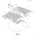
- Figure 6 illustrates a perspective view of a lighting assembly according to another embodiment.
- the lighting assembly includes a light source, a cooling system, one or more power supply units, and a mounting structure.
- the cooling system includes one or more cooling loops, each cooling loop including an evaporator, a vertically ascending pipe, a radiator and a return pipe.
- the lighting assembly of Figure 6 functions similarly as the lighting assembly of Figure 1 to provide cooling for the light source.
- the exemplary cooling system shown in Figure 6 includes two cooling loops, each cooling loop shares a common evaporator 114.
- Figure 7 illustrates a side view of the lighting assembly 102 of Figure 6 .
- a first cooling loop includes the evaporator 114, a vertically ascending pipe 116, a radiator 118, and a return pipe 120.
- a second cooling loop includes the evaporator 114, a vertically ascending pipe 126, a radiator 128 and another return pipe (not shown).
- Figures 6 and 7 also show an optional reflector 112. The light source is positioned within the reflector 112.
- the first cooling loop and the second cooling loop are each closed loop. Although two closed loop cooling systems are shown in the lighting assembly of Figures 6 and 7 , it is understood that a lighting assembly can be configured to include a single closed loop cooling system or three or more closed loop cooling systems.
- the radiator 118 and the radiator 128 are each coupled to an input header 119 and to an output header 121.
- a single condensing unit is formed having two separate radiator portions coupled via common input and output headers.
- separation of the radiators 118 and 128 forms a pathway therebetween within which accessory elements can be positioned.
- the vertically ascending pipes 116 and 126 are each coupled at one end to the evaporator 114 and at the other end to the input header 119.
- the return pipe 120 and the other return pipe (not shown) are each coupled at one end to the output header 121 and at the other end to the evaporator 114.
- the input header 119 laterally distributes the vapor received from the vertically ascending pipes 116 and 126.
- the radiators 118 and 128 can also include one or more fluid conduits coupled to the input header 119 and to the output header 121, and fins coupled to the fluid conduits.
- the fluid conduits can be arranged laterally and/or layered to form a vertical stack of fluid conduits, each layer separated by fins.
- the output header 121 collects the condensed liquid from the radiators 118 and 128.
- the lighting assembly includes a mounting structure 110 coupled to the evaporator 114 and positioned in the pathway between the radiators 118 and 128.
- the mounting structure 110 includes handles 111 for carrying the lighting assembly.
- the lighting assembly includes four power supplies 106.
- the power supplies 106 can be mounted to the mounting structure 110, as shown, the evaporator 114, the vertically ascending pipes 116 and 126 or some combination thereof.
- An external mounting base 107 is coupled to the mounting structure 110 and/or to the evaporator 114. Bracing elements 113 provide additional support and couple the radiators 118 and 128 to the mounting structure 110, the external mounting base 107, the evaporator 114 or some combination thereof.
- the external mounting base 107 is used to mount the lighting assembly.
- the external mounting base 107 is configured to receive a conduit, which in turn is mounted to an external support, such as a ceiling.
- a separate device electronics and housing such as device electronics 8 in Figures 1 and 2 , is not included.
- device electronics are included as part of a light source assembly, such as the light source 36 shown in Figure 3 and described below. It is understood that device electronics and housing such as the device electronics 8 in Figures 1 and 2 can be added to the lighting assembly 102, such as mounted to the mounting structure 110 and/or to the external mounting base 107.
- the evaporator is configured to transfer heat from a light source coupled to the evaporator to fluid within the evaporator.
- Figure 3 illustrates a bottom perspective exploded view of the evaporator 14 disassembled from an exemplary light source 36 according to an embodiment.
- the evaporator 14 includes a thermal exchange surface 32.
- the thermal exchange surface 32 is a rectangular, planar surface. Alternatively, the surface can be shaped other than a rectangle.
- the shape of the thermal exchange surface matches that of a corresponding thermal exchange surface of the light source.
- the thermal exchange surface 32 is made of a thermally conductive material, which can be the same or different than the material used to make the remainder of the evaporator.
- the light source 36 is thermally coupled to the thermal exchange surface 32 via a thermal interface material 34.
- the light source 36 is a plurality of LEDs mounted to a printed circuit board.
- Printed circuit boards are inherently flexible. Attaching such a flexible substrate to a rigid thermal exchange interface and achieving the requisite thermal interface between the two may require many fasteners, both along the perimeter and interior of the printed circuit board.
- the printed circuit board can be modified for enhanced rigidity.
- the printed circuit board is bonded thermally and physically to a thicker, rigid substrate, such as a metal plate, to form a board assembly.
- the rigid substrate is made of a thermally conductive material, such as aluminum. As such, the board assembly provides structural rigidity and thermal conductance. Bonding the metal plate to the printed circuit board also provides improved thermal communication over the entire overlapping areas of the metal plate and printed circuit board.
- the board assembly is fastened to the thermal interface surface 32 of the evaporator 14 via the thermal interface material 34.
- the rigid board assembly can be attached to the thermal interface surface 32 using fewer fasteners than if the printed circuit board alone is attached to the thermal interface surface 32.
- the board assembly can be attached to the thermal interface surface 32 using fasteners around the perimeter. No interior fasteners are needed in this case due to the rigidity of the board assembly. Due to the rigid structure, proper thermal communication is established across the entire board assembly and thermal interface surface even though fasteners are only sparsely applied, such as about the perimeter.
- mounting a printed circuit board may require a screw positioned every inch or so in a grid pattern to supply enough normal force to the printed circuit board to provide proper thermal communication with the thermal interface surface 32.
- the rigid substrate of the board assembly provides continuous contact of the substrate in response to a reduced number of normal force points, such as along the perimeter.
- the use of fewer fasteners provides a number of advantages including easier and faster assembly and lower costs. Additionally, fewer fasteners speeds the process of replacing a light source in an already installed lighting assembly.
- the board assembly is mounted to the evaporator 14 using any conventional mounting means including, but not limited to, screws, clamps, and/or brackets. To provide additional speed and ease for replacing an installed light source, the board assembly can be mounted using quick release latches or other mounting mechanisms that allow for quick and easy removal and replacement. In this manner, the rigid board assembly enables an installed lighting assembly to be "relampable" where the light source can be simply replaced.
- the thermal exchanging surface of the evaporator is a non-planar surface.
- a contour of the thermal exchanging surface is configured to match that of the corresponding thermal exchange surface of the light source.
- the light source is configured with a plurality of planar surfaces angled relative to each other.
- the light source is a multi-facet light source where each facet is a planar surface having a plurality of LEDs. Such a multi-facet light source is described in the co-pending U.S. Patent Application Serial No. 13/921,028, filed June 18, 2013 , and entitled "Multi-Facet Light Engine", which is hereby incorporated in its entirety be reference.
- the evaporator 14 has planar surfaces as in a rectangle or other trapezoidal configuration.
- the evaporator is configured as a hemispherical evaporator.
- a hemispherical design mimics the geometry of a pressure vessel with its spherical based shape.
- Such an evaporator configuration provides significantly improved hoop strength.
- the bottom side of the evaporator remains planar in order to interface with a planar light source.
- the bottom side is contoured to match some or all of a non-planar thermal exchange surface of the light source. Regardless of the bottom side configuration, at least an upper portion of the evaporator can have a hemispherical configuration.
- FIG 4 illustrates a top down perspective view of an exemplary evaporator 40 having a hemispherical configuration according to an embodiment.
- Figure 5 illustrates a cut out side view of the evaporator 40 of Figure 4 .
- the evaporator 40 includes an upper spherical casing 42 coupled to a lower base 44.
- the upper spherical casing 42 includes one or more openings. In the exemplary configuration shown in Figure 4 there are two opening 48 and 50. Each opening is coupled to a vertically ascending pipe.
- the opening 48 is coupled to the vertically ascending pipe 26 ( Figure 2 ) and the opening 50 is coupled to the vertically ascending pipe 16 ( Figure 2 ).
- the lower base 44 includes a support portion 52 configured to receive the upper spherical casing 42.
- the lower base 44 also includes a thermal interface plate 54.
- the thermal interface plate 54 includes an outer surface 56 and an inner surface 58.
- the outer surface 56 is thermally coupled to the light source.
- the outer surface 56 is planer, as shown in Figure 5 .
- the outer surface is non-planar and is configured to match some or all of a surface contour of the light source.
- the lower base 44 has a circular configuration, as shown in Figure 4 .
- the lower base 44 can also include additional threaded attachments for the light source, such as an external ring when the lower base has a circular shape.
- the lower base is alternatively shaped.
- the inner surface 58 is configured to promote nucleate boiling of the fluid.
- the inner surface 58 has an arrangement of fins and/or divots.
- the inner surface 58 includes a specialized surface finish that promotes nucleate boiling.
- the upper spherical casing 42 and the lower base 44 are designed with an interface that allows them to be made with different processes to optimize costs.
- the separation of the upper spherical casing and the lower base allows the upper portion to be cast, for example, while the lower base is machined, for example, to achieve higher precise and more optimal heat transfer.
- the lighting assembly is designed for high bay lighting, such as 40-50 feet high ceilings. In such an application, the lighting assembly generates 100-400 watts. In some applications, the lighting assembly generates more than 400 watts. In general, the lighting assembly is useful for those applications requiring lighting solutions with higher wattages than those found in typical office environments having 8-10 feet high ceilings.
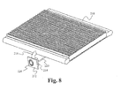
- FIG. 8 illustrates a perspective view of a lighting assembly configured for a vertically mounted light source according to an embodiment.
- Figure 9 illustrates an alternative perspective view of the lighting assembly of Figure 8 .
- the lighting assembly includes a vertically mounted light source, device electronics and a cooling system.
- the cooling system is a closed loop cooling system that includes an evaporator, a vertically ascending pipe, a radiator and a return pipe.
- the exemplary cooling system shown in Figures 8 and 9 includes an evaporator 214, a vertically ascending pipe 216, a radiator 218, and a return pipe 220.
- the cooling loop of Figures 8 and 9 functions similarly as the cooling loops of Figure 1 to provide cooling for the light source.
- the evaporator 214 is configured such that a side surface is the thermal exchange surface for transferring heat from the light source, as opposed to a bottom surface as in previous embodiments.
- the side thermal exchange surface of the evaporator 214 is configured and aligned on an opposing side of the PCB 212 than the LEDs 224.
- the side thermal exchange surface of the evaporator 214 is configured and aligned such that the side thermal exchange surface is in thermal contact with the entire back side of the PCB 212.
- the side thermal exchange surface is a rectangular, planar surface.
- the surface can be shaped other than a rectangle.
- the shape of the thermal exchange surface matches that of a corresponding thermal exchange surface of the light source.
- the thermal exchange surface is made of a thermally conductive material, which can be the same or different than the material used to make the remainder of the evaporator.
- the light source can be thermally coupled to the thermal exchange surface via a thermal interface material.
- the evaporator 214 is a fluid-based heat exchanger that conceptually functions as a boiling unit.
- the evaporator 214 includes a fluid reservoir that is filled or partially filled.
- a fluid level within the evaporator is at least as high as the highest edge of the light source.
- a fluid level in the evaporator 214 is at least as high as the top edge of the LEDs 224.
- the evaporator 214 is thermally coupled to the light source such that heat generated by the light source is transferred to the fluid within the evaporator 214.
- the heat causes fluid in the evaporator 14 to boil.
- the resulting vapor rises through the vertically ascending pipe 216 to the radiator 218.
- the configuration of the fluid and the vertically ascending pipe 216 enables a pumping means whereby the boiling fluid, including vapor and liquid, rise from the evaporator 214, through the pipe 216, and to the radiator 218 in a manner previously described.
- the radiator 218 is aligned at a decline, or downward angle relative to horizontal, such that one end is higher than the other end.
- the pipe 216 is coupled to a top portion of the radiator 218 and the return pipe 220 is coupled to a bottom portion of the radiator 218.
- the pipe 216 is coupled to an end of the top portion of the radiator 218.
- the return pipe 220 is coupled to an end of the bottom portion of the radiator 218. Vapor entering the radiator 218 from the pipe 216 condenses and the liquid flows downward through the radiator 218 to the return pipe 220. Due to the declining orientation of the radiator 218, liquid within the radiator is gravity fed toward the bottom end and to the return pipe 220.
- the return pipe 220 is aligned at a decline such that one end is higher than the other end such that liquid received from the radiator 218 is gravity fed to the evaporator 214.
- the radiator 218 can include an input header coupled to the pipe 216.
- the input header laterally distributes the vapor received from the pipe.
- the radiator can also include one or more fluid conduits coupled to the input header and fins coupled to the fluid conduits.
- the fluid conduits can be arranged laterally and/or layered to form a vertical stack of fluid conduits, each layer separated by fins.
- the radiator 218 can also include an output header coupled to the one or more fluid conduits.
- the output header is coupled to the return pipe.
- the radiator 218 is designed to dissipate the heat to the atmosphere using convection cooling without the need for fans blowing over the radiator.
- the light source can be a plurality of LEDs mounted to a PCB.
- PCBs are inherently flexible. Attaching such a flexible substrate to a rigid thermal exchange interface and achieving the requisite thermal interface between the two may require many fasteners, both along the perimeter and interior of the PCB.
- the PCB can be modified for enhanced rigidity, as described above.
- device electronics are included as part of a PCB 212. It is understood that device electronics separate from the light source, such as the device electronics in Figures 1-2 and 6-7 , can be added to the lighting assembly of Figures 8 and 9 .
- power is supplied via an external power supply cable coupled to the PCB 212.
- the lighting assembly of Figures 8 and 9 includes one or more power supplies such as the power supplies described in relation to Figures 1-2 and 6-7 .
- the lighting assembly of Figures 8 and 9 includes a mounting structure.
- a mounting structure can include any conventional mounting mechanisms for mounting and/or providing support to the radiator and/or the evaporator to a frame or other support element on the automobile.
- a mounting structure similar to those described above in relation to Figures 1-7 can be used.
Landscapes
- Engineering & Computer Science (AREA)
- General Engineering & Computer Science (AREA)
- Physics & Mathematics (AREA)
- Microelectronics & Electronic Packaging (AREA)
- Optics & Photonics (AREA)
- Mathematical Physics (AREA)
- Arrangement Of Elements, Cooling, Sealing, Or The Like Of Lighting Devices (AREA)
- Non-Portable Lighting Devices Or Systems Thereof (AREA)
Applications Claiming Priority (2)
| Application Number | Priority Date | Filing Date | Title |
|---|---|---|---|
| US201361886032P | 2013-10-02 | 2013-10-02 | |
| US14/502,805 US9366394B2 (en) | 2012-06-27 | 2014-09-30 | Automotive LED headlight cooling system |
Publications (4)
| Publication Number | Publication Date |
|---|---|
| EP2857745A2 true EP2857745A2 (fr) | 2015-04-08 |
| EP2857745A3 EP2857745A3 (fr) | 2015-07-29 |
| EP2857745C0 EP2857745C0 (fr) | 2023-07-05 |
| EP2857745B1 EP2857745B1 (fr) | 2023-07-05 |
Family
ID=51730332
Family Applications (1)
| Application Number | Title | Priority Date | Filing Date |
|---|---|---|---|
| EP14187452.9A Active EP2857745B1 (fr) | 2013-10-02 | 2014-10-02 | Ensemble d'eclairage avec systeme de refroidissement |
Country Status (2)
| Country | Link |
|---|---|
| US (1) | US9366394B2 (fr) |
| EP (1) | EP2857745B1 (fr) |
Families Citing this family (14)
| Publication number | Priority date | Publication date | Assignee | Title |
|---|---|---|---|---|
| US9117991B1 (en) | 2012-02-10 | 2015-08-25 | Flextronics Ap, Llc | Use of flexible circuits incorporating a heat spreading layer and the rigidizing specific areas within such a construction by creating stiffening structures within said circuits by either folding, bending, forming or combinations thereof |
| US9618185B2 (en) | 2012-03-08 | 2017-04-11 | Flextronics Ap, Llc | LED array for replacing flourescent tubes |
| US20140001496A1 (en) * | 2012-06-27 | 2014-01-02 | Flextronics Ap, Llc | Relampable led structure |
| US9366394B2 (en) | 2012-06-27 | 2016-06-14 | Flextronics Ap, Llc | Automotive LED headlight cooling system |
| US9748460B2 (en) | 2013-02-28 | 2017-08-29 | Flextronics Ap, Llc | LED back end assembly and method of manufacturing |
| US11026343B1 (en) | 2013-06-20 | 2021-06-01 | Flextronics Ap, Llc | Thermodynamic heat exchanger |
| US20150092410A1 (en) * | 2013-09-27 | 2015-04-02 | Lsi Industries, Inc. | Luminaire |
| CZ305708B6 (cs) * | 2014-12-16 | 2016-02-10 | Varroc Lighting Systems, s.r.o. | Světlomet |
| CA170038S (en) * | 2016-03-02 | 2017-03-23 | Dyson Technology Ltd | Lighting fixture |
| CA170044S (en) * | 2016-03-02 | 2017-03-23 | Dyson Technology Ltd | Lighting fixture |
| CA170043S (en) * | 2016-03-02 | 2017-03-23 | Dyson Technology Ltd | Lighting fixture |
| WO2017170153A1 (fr) * | 2016-03-31 | 2017-10-05 | 日本電気株式会社 | Refroidisseur à changement de phase et équipement électronique |
| IT201700082133A1 (it) * | 2017-07-19 | 2019-01-19 | Simaco Elettromeccanica S R L | Proiettore led raffreddato a liquidi |
| WO2021198851A1 (fr) * | 2020-03-31 | 2021-10-07 | Tvs Motor Company Limited | Ensemble phare |
Citations (1)
| Publication number | Priority date | Publication date | Assignee | Title |
|---|---|---|---|---|
| US20070273024A1 (en) | 2003-12-08 | 2007-11-29 | Henry Madsen | Cooling System with a Bubble Pump |
Family Cites Families (80)
| Publication number | Priority date | Publication date | Assignee | Title |
|---|---|---|---|---|
| US4069497A (en) | 1975-08-13 | 1978-01-17 | Emc Technology, Inc. | High heat dissipation mounting for solid state devices and circuits |
| FR2578638B1 (fr) * | 1985-03-08 | 1989-08-18 | Inst Francais Du Petrole | Procede de transfert de chaleur d'un fluide chaud a un fluide froid utilisant un fluide mixte comme agent caloporteur |
| US4712160A (en) | 1985-07-02 | 1987-12-08 | Matsushita Electric Industrial Co., Ltd. | Power supply module |
| US4899256A (en) | 1988-06-01 | 1990-02-06 | Chrysler Motors Corporation | Power module |
| US5101322A (en) | 1990-03-07 | 1992-03-31 | Motorola, Inc. | Arrangement for electronic circuit module |
| DE4015030C1 (fr) | 1990-05-10 | 1991-11-21 | Bicc-Vero Elektronics Gmbh, 2800 Bremen, De | |
| US5168919A (en) * | 1990-06-29 | 1992-12-08 | Digital Equipment Corporation | Air cooled heat exchanger for multi-chip assemblies |
| JP2642548B2 (ja) | 1991-09-26 | 1997-08-20 | 株式会社東芝 | 半導体装置およびその製造方法 |
| USRE36414E (en) | 1992-04-03 | 1999-11-30 | Sportlite, Inc. | Lighting apparatus |
| EP0605712B1 (fr) | 1992-07-17 | 1999-09-08 | Vlt Corporation | Empaquetage pour composants electroniques |
| US5272599A (en) | 1993-03-19 | 1993-12-21 | Compaq Computer Corporation | Microprocessor heat dissipation apparatus for a printed circuit board |
| US5838554A (en) | 1994-04-26 | 1998-11-17 | Comarco Wireless Technologies, Inc. | Small form factor power supply |
| US5502582A (en) * | 1994-09-02 | 1996-03-26 | Aavid Laboratories, Inc. | Light source cooler for LCD monitor |
| US5890794A (en) | 1996-04-03 | 1999-04-06 | Abtahi; Homayoon | Lighting units |
| US6274890B1 (en) | 1997-01-15 | 2001-08-14 | Kabushiki Kaisha Toshiba | Semiconductor light emitting device and its manufacturing method |
| US5920458A (en) | 1997-05-28 | 1999-07-06 | Lucent Technologies Inc. | Enhanced cooling of a heat dissipating circuit element |
| US6147869A (en) | 1997-11-24 | 2000-11-14 | International Rectifier Corp. | Adaptable planar module |
| US5933324A (en) | 1997-12-16 | 1999-08-03 | Intel Corporation | Apparatus for dissipating heat from a conductive layer in a circuit board |
| EP0981192A4 (fr) | 1998-03-14 | 2001-01-10 | Furukawa Electric Co Ltd | Dissipateur de chaleur destine a une ligne de transmission, ligne de transmission comprenant le dissipateur de chaleur et procede d'installation du dissipateur de chaleur sur la ligne de transmission |
| JP4121185B2 (ja) | 1998-06-12 | 2008-07-23 | 新電元工業株式会社 | 電子回路装置 |
| US6243269B1 (en) | 1998-12-29 | 2001-06-05 | Ncr Corporation | Centralized cooling interconnect for electronic packages |
| US20020008963A1 (en) | 1999-07-15 | 2002-01-24 | Dibene, Ii Joseph T. | Inter-circuit encapsulated packaging |
| AU2051001A (en) | 1999-12-01 | 2001-06-12 | Chip Coolers, Inc | Structural frame of thermally conductive material |
| US20010045297A1 (en) | 2000-02-01 | 2001-11-29 | Miller James D. | Molding of electrical devices with a thermally conductive and electrically insulative polymer composition |
| US6445580B1 (en) | 2000-06-09 | 2002-09-03 | International Business Machines Corporation | Adaptable heat dissipation device for a personal computer |
| US6549409B1 (en) | 2000-08-21 | 2003-04-15 | Vlt Corporation | Power converter assembly |
| JP2002168547A (ja) * | 2000-11-20 | 2002-06-14 | Global Cooling Bv | 熱サイホンによるcpu冷却装置 |
| JP3923258B2 (ja) | 2001-01-17 | 2007-05-30 | 松下電器産業株式会社 | 電力制御系電子回路装置及びその製造方法 |
| CN1464953A (zh) | 2001-08-09 | 2003-12-31 | 松下电器产业株式会社 | Led照明装置和卡型led照明光源 |
| US6775162B2 (en) | 2001-12-11 | 2004-08-10 | Cellex Power Products, Inc. | Self-regulated cooling system for switching power supplies using parasitic effects of switching |
| US6804117B2 (en) * | 2002-08-14 | 2004-10-12 | Thermal Corp. | Thermal bus for electronics systems |
| US7455444B2 (en) | 2004-07-06 | 2008-11-25 | Tseng-Lu Chien | Multiple light source night light |
| TW557119U (en) | 2003-01-24 | 2003-10-01 | Delta Electronics Inc | Casing structure capable of dissipating heat for electronic apparatus |
| TW592347U (en) | 2003-04-07 | 2004-06-11 | Leadtek Research Inc | Cooling device |
| US6882111B2 (en) | 2003-07-09 | 2005-04-19 | Tir Systems Ltd. | Strip lighting system incorporating light emitting devices |
| WO2005024331A1 (fr) * | 2003-09-02 | 2005-03-17 | Sharp Kabushiki Kaisha | Thermosiphon du type boucle, chambre de refroidissement a cycle stirling et appareil de refroidissement |
| TWI225713B (en) * | 2003-09-26 | 2004-12-21 | Bin-Juine Huang | Illumination apparatus of light emitting diodes and method of heat dissipation thereof |
| JP5004410B2 (ja) | 2004-04-26 | 2012-08-22 | Towa株式会社 | 光素子の樹脂封止成形方法および樹脂封止成形装置 |
| JP4252938B2 (ja) | 2004-07-07 | 2009-04-08 | 株式会社デンソー | 車両の車室照明装置 |
| JP5128047B2 (ja) | 2004-10-07 | 2013-01-23 | Towa株式会社 | 光デバイス及び光デバイスの生産方法 |
| US7858408B2 (en) | 2004-11-15 | 2010-12-28 | Koninklijke Philips Electronics N.V. | LED with phosphor tile and overmolded phosphor in lens |
| US7398818B2 (en) | 2004-12-28 | 2008-07-15 | California Institute Of Technology | Fluidic pump for heat management |
| KR100587017B1 (ko) | 2005-02-23 | 2006-06-08 | 삼성전기주식회사 | 발광 다이오드 패키지 및 그 제조 방법 |
| US7253744B2 (en) | 2005-05-23 | 2007-08-07 | The Boeing Company | Automatically adjusting passenger reading light system and method |
| KR100698009B1 (ko) * | 2005-07-05 | 2007-03-23 | 유기조 | 루프형 히트파이프를 구비한 엘이디 조명장치 |
| EP1904785A2 (fr) | 2005-07-08 | 2008-04-02 | Koninklijke Philips Electronics N.V. | Module d'eclairage pour la production de lumiere a motif de diffusion electriquement variable et son utilisation en tant qu'eclairage polyvalent |
| DE102005057154A1 (de) | 2005-11-30 | 2007-05-31 | BSH Bosch und Siemens Hausgeräte GmbH | Haushaltsgerät mit einem von einer Glastür her beleuchteten Innenraum |
| US7766511B2 (en) | 2006-04-24 | 2010-08-03 | Integrated Illumination Systems | LED light fixture |
| US7338186B1 (en) | 2006-08-30 | 2008-03-04 | Chaun-Choung Technology Corp. | Assembled structure of large-sized LED lamp |
| DE202006014933U1 (de) | 2006-09-28 | 2008-02-14 | Diehl Aerospace Gmbh | Beleuchtungsvorrichtung für eine Fahrzeugkabine |
| DE102006048323A1 (de) | 2006-10-06 | 2008-04-10 | Schefenacker Patents S.à.r.l. | Außenrückblickspiegel für Fahrzeuge, vorzugsweise für Kraftfahrzeuge |
| US7938558B2 (en) | 2007-05-04 | 2011-05-10 | Ruud Lighting, Inc. | Safety accommodation arrangement in LED package/lens structure |
| DE102007038911A1 (de) * | 2007-08-17 | 2009-02-19 | Osram Gesellschaft mit beschränkter Haftung | Kühlvorrichtung und Beleuchtungseinrichtung |
| US8262263B2 (en) * | 2007-11-16 | 2012-09-11 | Khanh Dinh | High reliability cooling system for LED lamps using dual mode heat transfer loops |
| US8878219B2 (en) | 2008-01-11 | 2014-11-04 | Cree, Inc. | Flip-chip phosphor coating method and devices fabricated utilizing method |
| KR100990640B1 (ko) | 2008-05-29 | 2010-10-29 | 삼성엘이디 주식회사 | 확산렌즈 및 확산렌즈를 이용한 발광소자 조립체 |
| DE102008031256A1 (de) | 2008-07-02 | 2010-01-07 | Osram Gesellschaft mit beschränkter Haftung | Beleuchtungseinheit für Fahrzeugscheinwerfer und Fahrzeugscheinwerfer |
| US9374856B2 (en) | 2008-09-23 | 2016-06-21 | Jeffrey Winton | Energy saving undercabinet lighting system using light emitting diodes |
| US20100097780A1 (en) | 2008-10-21 | 2010-04-22 | John Bryan Beatenbough | Refrigerated led illumination system |
| JP5757086B2 (ja) * | 2008-10-29 | 2015-07-29 | 日本電気株式会社 | 冷却構造及び電子機器並びに冷却方法 |
| CN105135238A (zh) | 2008-11-19 | 2015-12-09 | 罗姆股份有限公司 | Led照明装置 |
| JP4870826B2 (ja) | 2009-04-27 | 2012-02-08 | 株式会社エンプラス | 発光装置、面光源装置、及び表示装置 |
| US8227269B2 (en) | 2009-05-19 | 2012-07-24 | Intematix Corporation | Manufacture of light emitting devices with phosphor wavelength conversion |
| US8597963B2 (en) | 2009-05-19 | 2013-12-03 | Intematix Corporation | Manufacture of light emitting devices with phosphor wavelength conversion |
| US8440500B2 (en) | 2009-05-20 | 2013-05-14 | Interlight Optotech Corporation | Light emitting device |
| DE102009034841B4 (de) | 2009-07-27 | 2020-11-26 | Emz-Hanauer Gmbh & Co. Kgaa | Lichtabgabeeinrichtung für eine Trommel eines Haushaltsgeräts |
| US8378559B2 (en) * | 2009-08-20 | 2013-02-19 | Progressive Cooling Solutions, Inc. | LED bulb for high intensity discharge bulb replacement |
| JP5210997B2 (ja) * | 2009-08-28 | 2013-06-12 | 株式会社日立製作所 | 冷却システム、及び、それを用いる電子装置 |
| US20110063836A1 (en) | 2009-09-11 | 2011-03-17 | Glp German Light Products Gmbh | Support structure for a plurality of lenses, lens, lens system, and optical system |
| KR101054509B1 (ko) * | 2010-01-19 | 2011-08-05 | 박인택 | 발열체 냉각 장치 |
| EP3205958B1 (fr) | 2010-02-01 | 2019-11-13 | LG Electronics Inc. | Réfrigérateur |
| CN102753922B (zh) | 2010-03-03 | 2015-05-13 | 松下电器产业株式会社 | 冷藏库 |
| US8492977B2 (en) | 2010-07-23 | 2013-07-23 | Cree, Inc. | Lighting unit using a retro-formed component |
| US20120097985A1 (en) | 2010-10-21 | 2012-04-26 | Wen-Huang Liu | Light Emitting Diode (LED) Package And Method Of Fabrication |
| JP5276217B2 (ja) | 2010-10-22 | 2013-08-28 | パナソニック株式会社 | ランプ及び照明装置 |
| KR20120091839A (ko) | 2011-02-10 | 2012-08-20 | 삼성전자주식회사 | 플립칩 발광소자 패키지 및 그 제조 방법 |
| US8678611B2 (en) | 2011-08-25 | 2014-03-25 | Gt Biomescilt Light Limited | Light emitting diode lamp with light diffusing structure |
| KR101305437B1 (ko) * | 2012-03-22 | 2013-09-26 | 주식회사 루티마라이트 | 냉각 모듈 및 그를 포함하는 조명장치 |
| US9366394B2 (en) | 2012-06-27 | 2016-06-14 | Flextronics Ap, Llc | Automotive LED headlight cooling system |
| US20140001496A1 (en) | 2012-06-27 | 2014-01-02 | Flextronics Ap, Llc | Relampable led structure |
-
2014
- 2014-09-30 US US14/502,805 patent/US9366394B2/en not_active Expired - Fee Related
- 2014-10-02 EP EP14187452.9A patent/EP2857745B1/fr active Active
Patent Citations (1)
| Publication number | Priority date | Publication date | Assignee | Title |
|---|---|---|---|---|
| US20070273024A1 (en) | 2003-12-08 | 2007-11-29 | Henry Madsen | Cooling System with a Bubble Pump |
Also Published As
| Publication number | Publication date |
|---|---|
| US20150016123A1 (en) | 2015-01-15 |
| EP2857745C0 (fr) | 2023-07-05 |
| EP2857745A3 (fr) | 2015-07-29 |
| US9366394B2 (en) | 2016-06-14 |
| EP2857745B1 (fr) | 2023-07-05 |
Similar Documents
| Publication | Publication Date | Title |
|---|---|---|
| US9366394B2 (en) | Automotive LED headlight cooling system | |
| US9356214B2 (en) | Cooling system for LED device | |
| US7748876B2 (en) | LED lamp with a heat sink assembly | |
| US7994533B2 (en) | LED lamp | |
| US20090021944A1 (en) | Led lamp | |
| WO2020118629A1 (fr) | Dispositif électronique | |
| US20140184050A1 (en) | Lighting Apparatus | |
| US20130294070A1 (en) | High bay light | |
| KR100895694B1 (ko) | 히트 파이프형 방열장치 | |
| JP5769307B2 (ja) | 照明装置 | |
| CN101545622A (zh) | 发光二极管照明装置 | |
| US20150085503A1 (en) | Lighting apparatus | |
| KR100948955B1 (ko) | 조명장치 | |
| KR20170113178A (ko) | 방열 장치 및 그것을 구비하는 광 조사 장치 | |
| JP6816996B2 (ja) | 投光照明装置 | |
| JP5390781B2 (ja) | 光源冷却装置 | |
| KR200471596Y1 (ko) | Led 조명 장치를 위한 방열장치 | |
| US20130063933A1 (en) | Modular Integrated High Power LED Luminaire | |
| JP6813307B2 (ja) | 投光照明装置 | |
| CN101855494B (zh) | 均匀散热的照明组件 | |
| EP4237744B1 (fr) | Système de dissipation de la chaleur de lampe de véhicule | |
| TWI360620B (en) | Led lamp | |
| JP2013069607A (ja) | 沸騰冷却式led照明装置 | |
| JP2013069601A (ja) | 沸騰冷却式led照明装置 | |
| WO2020118628A1 (fr) | Structure de réduction des vibrations, procédé d'installation et dispositif électronique |
Legal Events
| Date | Code | Title | Description |
|---|---|---|---|
| PUAI | Public reference made under article 153(3) epc to a published international application that has entered the european phase |
Free format text: ORIGINAL CODE: 0009012 |
|
| 17P | Request for examination filed |
Effective date: 20141002 |
|
| AK | Designated contracting states |
Kind code of ref document: A2 Designated state(s): AL AT BE BG CH CY CZ DE DK EE ES FI FR GB GR HR HU IE IS IT LI LT LU LV MC MK MT NL NO PL PT RO RS SE SI SK SM TR |
|
| AX | Request for extension of the european patent |
Extension state: BA ME |
|
| PUAL | Search report despatched |
Free format text: ORIGINAL CODE: 0009013 |
|
| AK | Designated contracting states |
Kind code of ref document: A3 Designated state(s): AL AT BE BG CH CY CZ DE DK EE ES FI FR GB GR HR HU IE IS IT LI LT LU LV MC MK MT NL NO PL PT RO RS SE SI SK SM TR |
|
| AX | Request for extension of the european patent |
Extension state: BA ME |
|
| RIC1 | Information provided on ipc code assigned before grant |
Ipc: F21V 29/51 20150101AFI20150623BHEP Ipc: F21S 8/10 20060101ALN20150623BHEP Ipc: F21Y 101/02 20060101ALN20150623BHEP |
|
| R17P | Request for examination filed (corrected) |
Effective date: 20160128 |
|
| RBV | Designated contracting states (corrected) |
Designated state(s): AL AT BE BG CH CY CZ DE DK EE ES FI FR GB GR HR HU IE IS IT LI LT LU LV MC MK MT NL NO PL PT RO RS SE SI SK SM TR |
|
| STAA | Information on the status of an ep patent application or granted ep patent |
Free format text: STATUS: EXAMINATION IS IN PROGRESS |
|
| 17Q | First examination report despatched |
Effective date: 20170808 |
|
| REG | Reference to a national code |
Ref country code: DE Ref legal event code: R079 Free format text: PREVIOUS MAIN CLASS: F21V0029510000 Ipc: F21S0041153000 Ref country code: DE Ref legal event code: R079 Ref document number: 602014087520 Country of ref document: DE Free format text: PREVIOUS MAIN CLASS: F21V0029510000 Ipc: F21S0041153000 |
|
| RIC1 | Information provided on ipc code assigned before grant |
Ipc: F21S 45/47 20180101ALI20221108BHEP Ipc: F21V 29/51 20150101ALI20221108BHEP Ipc: F21K 9/20 20160101ALI20221108BHEP Ipc: F21S 41/153 20180101AFI20221108BHEP |
|
| GRAP | Despatch of communication of intention to grant a patent |
Free format text: ORIGINAL CODE: EPIDOSNIGR1 |
|
| STAA | Information on the status of an ep patent application or granted ep patent |
Free format text: STATUS: GRANT OF PATENT IS INTENDED |
|
| INTG | Intention to grant announced |
Effective date: 20230113 |
|
| GRAS | Grant fee paid |
Free format text: ORIGINAL CODE: EPIDOSNIGR3 |
|
| GRAA | (expected) grant |
Free format text: ORIGINAL CODE: 0009210 |
|
| STAA | Information on the status of an ep patent application or granted ep patent |
Free format text: STATUS: THE PATENT HAS BEEN GRANTED |
|
| AK | Designated contracting states |
Kind code of ref document: B1 Designated state(s): AL AT BE BG CH CY CZ DE DK EE ES FI FR GB GR HR HU IE IS IT LI LT LU LV MC MK MT NL NO PL PT RO RS SE SI SK SM TR |
|
| REG | Reference to a national code |
Ref country code: CH Ref legal event code: EP |
|
| REG | Reference to a national code |
Ref country code: AT Ref legal event code: REF Ref document number: 1585145 Country of ref document: AT Kind code of ref document: T Effective date: 20230715 |
|
| REG | Reference to a national code |
Ref country code: DE Ref legal event code: R096 Ref document number: 602014087520 Country of ref document: DE |
|
| REG | Reference to a national code |
Ref country code: IE Ref legal event code: FG4D |
|
| U01 | Request for unitary effect filed |
Effective date: 20230804 |
|
| U07 | Unitary effect registered |
Designated state(s): AT BE BG DE DK EE FI FR IT LT LU LV MT NL PT SE SI Effective date: 20230809 |
|
| REG | Reference to a national code |
Ref country code: LT Ref legal event code: MG9D |
|
| PG25 | Lapsed in a contracting state [announced via postgrant information from national office to epo] |
Ref country code: GR Free format text: LAPSE BECAUSE OF FAILURE TO SUBMIT A TRANSLATION OF THE DESCRIPTION OR TO PAY THE FEE WITHIN THE PRESCRIBED TIME-LIMIT Effective date: 20231006 |
|
| PG25 | Lapsed in a contracting state [announced via postgrant information from national office to epo] |
Ref country code: ES Free format text: LAPSE BECAUSE OF FAILURE TO SUBMIT A TRANSLATION OF THE DESCRIPTION OR TO PAY THE FEE WITHIN THE PRESCRIBED TIME-LIMIT Effective date: 20230705 |
|
| PG25 | Lapsed in a contracting state [announced via postgrant information from national office to epo] |
Ref country code: IS Free format text: LAPSE BECAUSE OF FAILURE TO SUBMIT A TRANSLATION OF THE DESCRIPTION OR TO PAY THE FEE WITHIN THE PRESCRIBED TIME-LIMIT Effective date: 20231105 |
|
| PG25 | Lapsed in a contracting state [announced via postgrant information from national office to epo] |
Ref country code: RS Free format text: LAPSE BECAUSE OF FAILURE TO SUBMIT A TRANSLATION OF THE DESCRIPTION OR TO PAY THE FEE WITHIN THE PRESCRIBED TIME-LIMIT Effective date: 20230705 Ref country code: NO Free format text: LAPSE BECAUSE OF FAILURE TO SUBMIT A TRANSLATION OF THE DESCRIPTION OR TO PAY THE FEE WITHIN THE PRESCRIBED TIME-LIMIT Effective date: 20231005 Ref country code: IS Free format text: LAPSE BECAUSE OF FAILURE TO SUBMIT A TRANSLATION OF THE DESCRIPTION OR TO PAY THE FEE WITHIN THE PRESCRIBED TIME-LIMIT Effective date: 20231105 Ref country code: HR Free format text: LAPSE BECAUSE OF FAILURE TO SUBMIT A TRANSLATION OF THE DESCRIPTION OR TO PAY THE FEE WITHIN THE PRESCRIBED TIME-LIMIT Effective date: 20230705 Ref country code: GR Free format text: LAPSE BECAUSE OF FAILURE TO SUBMIT A TRANSLATION OF THE DESCRIPTION OR TO PAY THE FEE WITHIN THE PRESCRIBED TIME-LIMIT Effective date: 20231006 Ref country code: ES Free format text: LAPSE BECAUSE OF FAILURE TO SUBMIT A TRANSLATION OF THE DESCRIPTION OR TO PAY THE FEE WITHIN THE PRESCRIBED TIME-LIMIT Effective date: 20230705 |
|
| PG25 | Lapsed in a contracting state [announced via postgrant information from national office to epo] |
Ref country code: PL Free format text: LAPSE BECAUSE OF FAILURE TO SUBMIT A TRANSLATION OF THE DESCRIPTION OR TO PAY THE FEE WITHIN THE PRESCRIBED TIME-LIMIT Effective date: 20230705 |
|
| REG | Reference to a national code |
Ref country code: DE Ref legal event code: R097 Ref document number: 602014087520 Country of ref document: DE |
|
| PG25 | Lapsed in a contracting state [announced via postgrant information from national office to epo] |
Ref country code: SM Free format text: LAPSE BECAUSE OF FAILURE TO SUBMIT A TRANSLATION OF THE DESCRIPTION OR TO PAY THE FEE WITHIN THE PRESCRIBED TIME-LIMIT Effective date: 20230705 Ref country code: RO Free format text: LAPSE BECAUSE OF FAILURE TO SUBMIT A TRANSLATION OF THE DESCRIPTION OR TO PAY THE FEE WITHIN THE PRESCRIBED TIME-LIMIT Effective date: 20230705 Ref country code: CZ Free format text: LAPSE BECAUSE OF FAILURE TO SUBMIT A TRANSLATION OF THE DESCRIPTION OR TO PAY THE FEE WITHIN THE PRESCRIBED TIME-LIMIT Effective date: 20230705 Ref country code: SK Free format text: LAPSE BECAUSE OF FAILURE TO SUBMIT A TRANSLATION OF THE DESCRIPTION OR TO PAY THE FEE WITHIN THE PRESCRIBED TIME-LIMIT Effective date: 20230705 |
|
| PLBE | No opposition filed within time limit |
Free format text: ORIGINAL CODE: 0009261 |
|
| STAA | Information on the status of an ep patent application or granted ep patent |
Free format text: STATUS: NO OPPOSITION FILED WITHIN TIME LIMIT |
|
| PG25 | Lapsed in a contracting state [announced via postgrant information from national office to epo] |
Ref country code: MC Free format text: LAPSE BECAUSE OF FAILURE TO SUBMIT A TRANSLATION OF THE DESCRIPTION OR TO PAY THE FEE WITHIN THE PRESCRIBED TIME-LIMIT Effective date: 20230705 |
|
| REG | Reference to a national code |
Ref country code: CH Ref legal event code: PL |
|
| 26N | No opposition filed |
Effective date: 20240408 |
|
| U90 | Renewal fees not paid: noting of loss of rights |
Free format text: RENEWAL FEE NOT PAID FOR YEAR 10 Effective date: 20240516 |
|
| GBPC | Gb: european patent ceased through non-payment of renewal fee |
Effective date: 20231005 |
|
| PG25 | Lapsed in a contracting state [announced via postgrant information from national office to epo] |
Ref country code: GB Free format text: LAPSE BECAUSE OF NON-PAYMENT OF DUE FEES Effective date: 20231005 |
|
| PG25 | Lapsed in a contracting state [announced via postgrant information from national office to epo] |
Ref country code: CH Free format text: LAPSE BECAUSE OF NON-PAYMENT OF DUE FEES Effective date: 20231031 |
|
| PG25 | Lapsed in a contracting state [announced via postgrant information from national office to epo] |
Ref country code: GB Free format text: LAPSE BECAUSE OF NON-PAYMENT OF DUE FEES Effective date: 20231005 Ref country code: CH Free format text: LAPSE BECAUSE OF NON-PAYMENT OF DUE FEES Effective date: 20231031 |
|
| PG25 | Lapsed in a contracting state [announced via postgrant information from national office to epo] |
Ref country code: IE Free format text: LAPSE BECAUSE OF NON-PAYMENT OF DUE FEES Effective date: 20231002 |
|
| U93 | Unitary patent lapsed |
Free format text: RENEWAL FEE NOT PAID Effective date: 20231031 |
|
| PG25 | Lapsed in a contracting state [announced via postgrant information from national office to epo] |
Ref country code: IE Free format text: LAPSE BECAUSE OF NON-PAYMENT OF DUE FEES Effective date: 20231002 |
|
| PG25 | Lapsed in a contracting state [announced via postgrant information from national office to epo] |
Ref country code: CY Free format text: LAPSE BECAUSE OF FAILURE TO SUBMIT A TRANSLATION OF THE DESCRIPTION OR TO PAY THE FEE WITHIN THE PRESCRIBED TIME-LIMIT; INVALID AB INITIO Effective date: 20141002 |
|
| PG25 | Lapsed in a contracting state [announced via postgrant information from national office to epo] |
Ref country code: HU Free format text: LAPSE BECAUSE OF FAILURE TO SUBMIT A TRANSLATION OF THE DESCRIPTION OR TO PAY THE FEE WITHIN THE PRESCRIBED TIME-LIMIT; INVALID AB INITIO Effective date: 20141002 |
|
| PG25 | Lapsed in a contracting state [announced via postgrant information from national office to epo] |
Ref country code: TR Free format text: LAPSE BECAUSE OF FAILURE TO SUBMIT A TRANSLATION OF THE DESCRIPTION OR TO PAY THE FEE WITHIN THE PRESCRIBED TIME-LIMIT Effective date: 20230705 |