EP2857768A1 - Klimaanlage - Google Patents
Klimaanlage Download PDFInfo
- Publication number
- EP2857768A1 EP2857768A1 EP20130777485 EP13777485A EP2857768A1 EP 2857768 A1 EP2857768 A1 EP 2857768A1 EP 20130777485 EP20130777485 EP 20130777485 EP 13777485 A EP13777485 A EP 13777485A EP 2857768 A1 EP2857768 A1 EP 2857768A1
- Authority
- EP
- European Patent Office
- Prior art keywords
- heat exchanger
- auxiliary heat
- indoor
- evaporation
- temperature
- Prior art date
- Legal status (The legal status is an assumption and is not a legal conclusion. Google has not performed a legal analysis and makes no representation as to the accuracy of the status listed.)
- Granted
Links
Images


Classifications
-
- F—MECHANICAL ENGINEERING; LIGHTING; HEATING; WEAPONS; BLASTING
- F24—HEATING; RANGES; VENTILATING
- F24F—AIR-CONDITIONING; AIR-HUMIDIFICATION; VENTILATION; USE OF AIR CURRENTS FOR SCREENING
- F24F13/00—Details common to, or for air-conditioning, air-humidification, ventilation or use of air currents for screening
- F24F13/30—Arrangement or mounting of heat-exchangers
-
- F—MECHANICAL ENGINEERING; LIGHTING; HEATING; WEAPONS; BLASTING
- F24—HEATING; RANGES; VENTILATING
- F24F—AIR-CONDITIONING; AIR-HUMIDIFICATION; VENTILATION; USE OF AIR CURRENTS FOR SCREENING
- F24F1/00—Room units for air-conditioning, e.g. separate or self-contained units or units receiving primary air from a central station
- F24F1/0007—Indoor units, e.g. fan coil units
- F24F1/0059—Indoor units, e.g. fan coil units characterised by heat exchangers
- F24F1/0063—Indoor units, e.g. fan coil units characterised by heat exchangers by the mounting or arrangement of the heat exchangers
-
- F—MECHANICAL ENGINEERING; LIGHTING; HEATING; WEAPONS; BLASTING
- F24—HEATING; RANGES; VENTILATING
- F24F—AIR-CONDITIONING; AIR-HUMIDIFICATION; VENTILATION; USE OF AIR CURRENTS FOR SCREENING
- F24F1/00—Room units for air-conditioning, e.g. separate or self-contained units or units receiving primary air from a central station
- F24F1/0007—Indoor units, e.g. fan coil units
- F24F1/0083—Indoor units, e.g. fan coil units with dehumidification means
-
- F—MECHANICAL ENGINEERING; LIGHTING; HEATING; WEAPONS; BLASTING
- F24—HEATING; RANGES; VENTILATING
- F24F—AIR-CONDITIONING; AIR-HUMIDIFICATION; VENTILATION; USE OF AIR CURRENTS FOR SCREENING
- F24F11/00—Control or safety arrangements
- F24F11/89—Arrangement or mounting of control or safety devices
-
- F—MECHANICAL ENGINEERING; LIGHTING; HEATING; WEAPONS; BLASTING
- F24—HEATING; RANGES; VENTILATING
- F24F—AIR-CONDITIONING; AIR-HUMIDIFICATION; VENTILATION; USE OF AIR CURRENTS FOR SCREENING
- F24F3/00—Air-conditioning systems in which conditioned primary air is supplied from one or more central stations to distributing units in the rooms or spaces where it may receive secondary treatment; Apparatus specially designed for such systems
- F24F3/12—Air-conditioning systems in which conditioned primary air is supplied from one or more central stations to distributing units in the rooms or spaces where it may receive secondary treatment; Apparatus specially designed for such systems characterised by the treatment of the air otherwise than by heating and cooling
- F24F3/14—Air-conditioning systems in which conditioned primary air is supplied from one or more central stations to distributing units in the rooms or spaces where it may receive secondary treatment; Apparatus specially designed for such systems characterised by the treatment of the air otherwise than by heating and cooling by humidification; by dehumidification
-
- F—MECHANICAL ENGINEERING; LIGHTING; HEATING; WEAPONS; BLASTING
- F25—REFRIGERATION OR COOLING; COMBINED HEATING AND REFRIGERATION SYSTEMS; HEAT PUMP SYSTEMS; MANUFACTURE OR STORAGE OF ICE; LIQUEFACTION SOLIDIFICATION OF GASES
- F25B—REFRIGERATION MACHINES, PLANTS OR SYSTEMS; COMBINED HEATING AND REFRIGERATION SYSTEMS; HEAT PUMP SYSTEMS
- F25B13/00—Compression machines, plants or systems, with reversible cycle
-
- F—MECHANICAL ENGINEERING; LIGHTING; HEATING; WEAPONS; BLASTING
- F25—REFRIGERATION OR COOLING; COMBINED HEATING AND REFRIGERATION SYSTEMS; HEAT PUMP SYSTEMS; MANUFACTURE OR STORAGE OF ICE; LIQUEFACTION SOLIDIFICATION OF GASES
- F25B—REFRIGERATION MACHINES, PLANTS OR SYSTEMS; COMBINED HEATING AND REFRIGERATION SYSTEMS; HEAT PUMP SYSTEMS
- F25B40/00—Subcoolers, desuperheaters or superheaters
- F25B40/02—Subcoolers
-
- F—MECHANICAL ENGINEERING; LIGHTING; HEATING; WEAPONS; BLASTING
- F24—HEATING; RANGES; VENTILATING
- F24F—AIR-CONDITIONING; AIR-HUMIDIFICATION; VENTILATION; USE OF AIR CURRENTS FOR SCREENING
- F24F2140/00—Control inputs relating to system states
- F24F2140/20—Heat-exchange fluid temperature
-
- F—MECHANICAL ENGINEERING; LIGHTING; HEATING; WEAPONS; BLASTING
- F25—REFRIGERATION OR COOLING; COMBINED HEATING AND REFRIGERATION SYSTEMS; HEAT PUMP SYSTEMS; MANUFACTURE OR STORAGE OF ICE; LIQUEFACTION SOLIDIFICATION OF GASES
- F25B—REFRIGERATION MACHINES, PLANTS OR SYSTEMS; COMBINED HEATING AND REFRIGERATION SYSTEMS; HEAT PUMP SYSTEMS
- F25B2313/00—Compression machines, plants or systems with reversible cycle not otherwise provided for
- F25B2313/023—Compression machines, plants or systems with reversible cycle not otherwise provided for using multiple indoor units
- F25B2313/0234—Compression machines, plants or systems with reversible cycle not otherwise provided for using multiple indoor units in series arrangements
-
- F—MECHANICAL ENGINEERING; LIGHTING; HEATING; WEAPONS; BLASTING
- F25—REFRIGERATION OR COOLING; COMBINED HEATING AND REFRIGERATION SYSTEMS; HEAT PUMP SYSTEMS; MANUFACTURE OR STORAGE OF ICE; LIQUEFACTION SOLIDIFICATION OF GASES
- F25B—REFRIGERATION MACHINES, PLANTS OR SYSTEMS; COMBINED HEATING AND REFRIGERATION SYSTEMS; HEAT PUMP SYSTEMS
- F25B2313/00—Compression machines, plants or systems with reversible cycle not otherwise provided for
- F25B2313/031—Sensor arrangements
- F25B2313/0314—Temperature sensors near the indoor heat exchanger
Definitions
- the present invention relates to an air conditioner configured to perform a dehumidification operation.
- an auxiliary heat exchanger is disposed rearward of a main heat exchanger; and a refrigerant evaporates only in the auxiliary heat exchanger to locally perform dehumidification so that dehumidification can be performed even under a low load (even when the number of revolution of a compressor is small), for example, when the difference between room temperature and a set temperature is sufficiently small and therefore the required cooling capacity is small.
- a low load even when the number of revolution of a compressor is small
- an evaporation region is limited to be within the auxiliary heat exchanger, and a temperature sensor is disposed downstream of the evaporation region, to make control so that the superheat degree is constant.
- Patent Literature 1 Japanese Unexamined Patent Publication No. 14727/1997 ( Tokukaihei 09-14727 )
- a temperature sensor for detecting the completion of the evaporation is provided in the vicinity of an outlet of the auxiliary heat exchanger in the above air conditioner, the sensor is situated nearer to a liquid side in the indoor heat exchanger. Therefore, in a cooling operation under a high load, the sensor detects a higher temperature which is improper as the evaporation temperature of the heat exchanger, on account of a pressure drop in the refrigerant. Meanwhile, in a heating operation, the sensor detects a temperature which is lower than the actual condensation temperature and is improper as the condensation temperature, on account of subcooling. Then, the liquid may be sucked by the compressor, resulting in a loss of reliability of the compressor.
- an object of the present invention is to provide an air conditioner in which a sensor for detecting the completion of the evaporation of a liquid refrigerant also serves as a sensor for detecting a condensation temperature in a heating operation and/or an evaporation temperature in a cooling operation.
- An air conditioner includes a refrigerant circuit in which a compressor, an outdoor heat exchanger, an expansion valve, and an indoor heat exchanger are connected to one another.
- the indoor heat exchanger includes an auxiliary heat exchanger which is disposed on a most windward side and to which a liquid refrigerant is supplied in a dehumidification operation, and a main heat exchanger disposed leeward from the auxiliary heat exchanger.
- the auxiliary heat exchanger includes an evaporation region where the liquid refrigerant evaporates and a superheat region downstream of the evaporation region.
- a temperature detecting means for detecting completion of the evaporation of the liquid refrigerant in the auxiliary heat exchanger is disposed downstream of the auxiliary heat exchanger.
- the temperature detecting means is disposed in or in the vicinity of a middle of a refrigerant path in the indoor heat exchanger.
- the condensation temperature in the heating operation and/or the evaporation temperature in the cooling operation is/are detected using the temperature detecting means for detecting the completion of the evaporation of the liquid refrigerant in the auxiliary heat exchanger in the dehumidification operation.
- a liquid inlet of the auxiliary heat exchanger is provided at a lower portion of the auxiliary heat exchanger; and the temperature detecting means is disposed in the vicinity of an upper end of the auxiliary heat exchanger.
- the main heat exchanger includes a front heat exchanger disposed on a front side in the indoor unit, and a rear heat exchanger disposed on a rear side in the indoor unit; and the auxiliary heat exchanger is disposed forward of the front heat exchanger.
- the present invention provides the following advantageous effects.
- first aspect of the present invention if the refrigerant is in a fully superheated state at an outlet of the auxiliary heat exchanger during the dehumidification operation, air passing through this superheat region is hardly cooled, and therefore does not cool heat-transfer tubes leeward from this region. Accordingly, by detecting the temperature of the refrigerant circuit leeward from the auxiliary heat exchanger, it is possible to determine whether the refrigerant is in the superheated state at the outlet of the auxiliary heat exchanger. Further, avoided is unstable operation resulting from the detection of an improper temperature, which is different from a proper temperature due to the subcooling in the heating operation or the pressure drop in the cooling operation.
- the condensation temperature in the heating operation and/or the evaporation temperature in the cooling operation is/are detected using the temperature detecting means for detecting the completion of the evaporation of the liquid refrigerant in the auxiliary heat exchanger in the dehumidification operation.
- the air conditioner 1 of this embodiment includes: an indoor unit 2 installed inside a room; and an outdoor unit 3 installed outside the room.
- the air conditioner 1 further includes a refrigerant circuit in which a compressor 10, a four-way valve 11, an outdoor heat exchanger 12, an expansion valve 13, and an indoor heat exchanger 14 are connected to one another.
- the outdoor heat exchanger 12 is connected to a discharge port of the compressor 10 via the four-way valve 11, and the expansion valve 13 is connected to the outdoor heat exchanger 12.
- one end of the indoor heat exchanger 14 is connected to the expansion valve 13, and the other end of the indoor heat exchanger 14 is connected to an intake port of the compressor 10 via the four-way valve 11.
- the indoor heat exchanger 14 includes an auxiliary heat exchanger 20 and a main heat exchanger 21.
- the air conditioner 1 operations in a cooling operation mode, in a predetermined dehumidification operation mode, and in a heating operation mode are possible.
- various operations are possible: selecting one of the operation modes to start the operation, changing the operation mode, stopping the operation, and the like. Further, using the remote controller, it is possible to adjust indoor temperature setting, and to change the air volume of the indoor unit 2 by changing the number of revolutions of an indoor fan.
- a refrigerant discharged from the compressor 10 flows, from the four-way valve 11, through the outdoor heat exchanger 12, the expansion valve 13, and the auxiliary heat exchanger 20, to the main heat exchanger 21 in order; and the refrigerant having passed through the main heat exchanger 21 returns back to the compressor 10 via the four-way valve 11. That is, the outdoor heat exchanger 12 functions as a condenser, and the indoor heat exchanger 14 (the auxiliary heat exchanger 20 and the main heat exchanger 21) functions as an evaporator.
- the state of the four-way valve 11 is switched, to form a heating cycle in which: the refrigerant discharged from the compressor 10 flows, from the four-way valve 11, through the main heat exchanger 21, the auxiliary heat exchanger 20, and the expansion valve 13, to the outdoor heat exchanger 12 in order; and the refrigerant having passed through the outdoor heat exchanger 12 returns back to the compressor 10 via the four-way valve 11, as indicated with broken arrows in the figure. That is, the indoor heat exchanger 14 (the auxiliary heat exchanger 20 and the main heat exchanger 21) functions as the condenser, and the outdoor heat exchanger 12 functions as the evaporator.
- the indoor unit 2 has, on its upper surface, an air inlet 2a through which indoor air is taken in.
- the indoor unit 2 further has, on a lower portion of its front surface, an air outlet 2b through which air for air conditioning comes out.
- an airflow path is formed from the air inlet 2a to the air outlet 2b.
- the indoor heat exchanger 14 and a cross-flow indoor fan 16 are disposed. Therefore, as the indoor fan 16 rotates, the indoor air is taken into the indoor unit 1 through the air inlet 2a.
- the air taken in through the air inlet 2a flows through the auxiliary heat exchanger 20 and the main heat exchanger 21 toward the indoor fan 16. Meanwhile, in a rear portion of the indoor unit 2, the air taken in through the air inlet 2a flows through the main heat exchanger 21 toward the indoor fan 16.
- the indoor heat exchanger 14 includes: the auxiliary heat exchanger 20; and the main heat exchanger 21 located downstream of the auxiliary heat exchanger 20 in an operation in the cooling operation mode or in the predetermined dehumidification operation mode.
- the main heat exchanger 21 includes: a front heat exchanger 21a disposed on a front side of the indoor unit 2; and a rear heat exchanger 21b disposed on a rear side of the indoor unit 2.
- the heat exchangers 21a and 21b are arranged in a shape of a counter-V around the indoor fan 16.
- the auxiliary heat exchanger 20 is disposed forward of the front heat exchanger 21a.
- Each of the auxiliary heat exchanger 20 and the main heat exchanger 21 includes heat exchanger pipes and a plurality of fins.
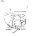
- a liquid refrigerant is supplied through a liquid inlet 17a provided in the vicinity of a lower end of the auxiliary heat exchanger 20, and the thus supplied liquid refrigerant flows toward an upper end of the auxiliary heat exchanger 20, as shown in FIG. 3 .
- the refrigerant is discharged through an outlet 17b provided in the vicinity of the upper end of the auxiliary heat exchanger 20, and then flows to a branching section 18a.
- the refrigerant is divided at the branching section 18a into branches, which are respectively supplied, via three inlets 17c of the main heat exchanger 21, to a lower portion and an upper portion of the front heat exchanger 21a and to the rear heat exchanger 21b.
- the branched refrigerant is discharged through outlets 17d, to merge together at a merging section 18b.
- the refrigerant flows in a reverse direction of the above direction.
- the liquid refrigerant supplied through the liquid inlet 17a of the auxiliary heat exchanger 20 all evaporates midway in the auxiliary heat exchanger 20, i.e., before reaching the outlet. Therefore, only a partial area in the vicinity of the liquid inlet 17a of the auxiliary heat exchanger 20 is an evaporation region where the liquid refrigerant evaporates.
- only the upstream partial area in the auxiliary heat exchanger 20 is the evaporation region, while (i) the area downstream of the evaporation region in the auxiliary heat exchanger 20 and (ii) the main heat exchanger 21 each functions as a superheat region, in the indoor heat exchanger 14.
- the refrigerant having flowed through the superheat region in the vicinity of the upper end of the auxiliary heat exchanger 20 flows through the lower portion of the front heat exchanger 21a disposed leeward from a lower portion of the auxiliary heat exchanger 20. Therefore, among the air taken in through the air inlet 2a, air having been cooled in the evaporation region of the auxiliary heat exchanger 20 is heated by the front heat exchanger 21a, and then blown out from the air outlet 2b.
- air having flowed through the superheat region of the auxiliary heat exchanger 20 and through the front heat exchanger 21a, and air having flowed through the rear heat exchanger 21b are blown out from the air outlet 2b at a temperature substantially the same as an indoor temperature.
- an evaporation temperature sensor 30 is attached to the outdoor unit 3, as shown in FIG. 1 .
- the evaporation temperature sensor 30 is configured to detect an evaporation temperature and is disposed downstream of the expansion valve 13 in the refrigerant circuit.
- an indoor temperature sensor 31 configured to detect the indoor temperature (the temperature of the air taken in through the air inlet 2a of the indoor unit 2); and an indoor heat exchanger temperature sensor 32 configured to detect whether evaporation of the liquid refrigerant is completed in the auxiliary heat exchanger 20.
- the indoor heat exchanger temperature sensor 32 is disposed in the vicinity of the upper end of the auxiliary heat exchanger 20 and leeward from the auxiliary heat exchanger 20. Further, in the superheat region in the vicinity of the upper end of the auxiliary heat exchanger 20, the air taken in through the air inlet 2a is hardly cooled. Therefore, when the temperature detected by the indoor heat exchanger temperature sensor 32 is substantially the same as the indoor temperature detected by the indoor temperature sensor 31, it is indicated that evaporation is completed midway in the auxiliary heat exchanger 20, and that the area in the vicinity of the upper end of the auxiliary heat exchanger 20 is the superheat region.
- the indoor heat exchanger temperature sensor 32 is provided to a heat-transfer tube in a middle portion of the indoor heat exchanger 14. Thus, in or in the vicinity of the middle portion of the indoor heat exchanger 14, detected is/are the condensation temperature in the heating operation and/or the evaporation temperature in the cooling operation.
- the control unit of the air conditioner 1 is connected with: the compressor 10; the four-way valve 11; the expansion valve 13; a motor 16a for driving the indoor fan 16; the evaporation temperature sensor 30; the indoor temperature sensor 31; and the indoor heat exchanger temperature sensor 32. Therefore, the control unit controls the operation of the air conditioner 1 based on: a command from the remote controller (for the start of the operation, for indoor temperature setting, or the like); the evaporation temperature detected by the evaporation temperature sensor 30; the indoor temperature detected by the indoor temperature sensor 31 (the temperature of the intake air); and a heat exchanger middle temperature detected by the indoor heat exchanger temperature sensor 32.
- the auxiliary heat exchanger 20 includes the evaporation region where the liquid refrigerant evaporates and the superheat region downstream of the evaporation region in the predetermined dehumidification operation mode.
- the compressor 10 and the expansion valve 13 are controlled so that the extent of the evaporation region varies depending on a load.
- the extent varies depending on a load means that the extent varies depending on the quantity of heat supplied to the evaporation region, and the quantity of heat is determined, for example, by the indoor temperature (the temperature of the intake air) and an indoor air volume.
- the load corresponds to a required dehumidification capacity (required cooling capacity), and the load is determined taking into account, for example, the difference between the indoor temperature and the set temperature.
- the compressor 10 is controlled based on the difference between the indoor temperature and the set temperature.
- the difference between the indoor temperature and the set temperature is large, the load is high, and therefore the compressor 10 is controlled so that its frequency increases.
- the difference between the indoor temperature and the set temperature is small, the load is low, and therefore the compressor 10 is controlled so that its frequency decreases.
- the expansion valve 13 is controlled based on the evaporation temperature detected by the evaporation temperature sensor 30. While the frequency of the compressor 10 is controlled as described above, the expansion valve 13 is controlled so that the evaporation temperature falls within a predetermined temperature range (10 to 14 degrees Celsius) close to a target evaporation temperature (12 degrees Celsius) . It is preferable that the predetermined evaporation temperature range is constant, irrespective of the frequency of the compressor 10. However, the predetermined range may be slightly changed with the change of the frequency as long as the predetermined range is substantially constant.
- the compressor 10 and the expansion valve 13 are controlled depending on the load in the predetermined dehumidification operation mode, and thereby changing the extent of the evaporation region of the auxiliary heat exchanger 20, and causing the evaporation temperature to fall within the predetermined temperature range.
- each of the auxiliary heat exchanger 20 and the front heat exchanger 21a has twelve rows of the heat-transfer tubes.
- the number of rows of the tubes functioning as the evaporation region in the auxiliary heat exchanger 20 in the predetermined dehumidification operation mode is not less than a half of the total number of rows of the tubes of the front heat exchanger 21a, it is possible to sufficiently increase the extent of the evaporation region of the auxiliary heat exchanger, and therefore a variation in the load is addressed sufficiently.
- This structure is effective especially under a high load.
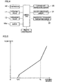
- FIG. 5 is a graph showing how the flow rate changes when the opening degree of the expansion valve 13 is changed.
- the opening degree of the expansion valve 13 continuously changes with the number of driving pulses input to the expansion valve 13. As the opening degree decreases, the flow rate of the refrigerant flowing through the expansion valve 13 decreases.
- the expansion valve 13 is fully closed when the opening degree is t0. In the range of the opening degrees t0 to t1, the flow rate increases at a first gradient as the opening degree increases. In the range of the opening degrees t1 to t2, the flow rate increases at a second gradient as the opening degree increases. Note that the first gradient is larger than the second gradient.
- the frequency of the compressor 10 is decreased and the opening degree of the expansion valve 13 is changed so as to decrease. Therefore, the extent of the evaporation region of the auxiliary heat exchanger 20 becomes smaller than that of the predetermined size, and this decreases the volume of the air actually passing through the evaporation region even when the volume of the air taken into the indoor unit 2 is constant.
- the air conditioner 1 of this embodiment if the refrigerant is in a fully superheated state at the outlet of the auxiliary heat exchanger 20 during the dehumidification operation, air passing through this superheat region is hardly cooled, and therefore does not cool heat-transfer tubes leeward from this region. Accordingly, by detecting the temperature of the refrigerant circuit leeward from the auxiliary heat exchanger 20, it is possible to determine whether the refrigerant is in the superheated state at the outlet of the auxiliary heat exchanger 20. Further, avoided is unstable operation resulting from the detection of an improper temperature, which is different from a proper temperature due to the subcooling in the heating operation or the pressure drop in the cooling operation.
- the indoor heat exchanger temperature sensor 32 is provided to the heat exchanger pipe in the middle portion of the indoor heat exchanger 14. Therefore, in or in the vicinity of the middle portion of the indoor heat exchanger 14, detected is/are the condensation temperature in the heating operation and/or the evaporation temperature in the cooling operation.
- the liquid inlet 17a of the auxiliary heat exchanger 20 is provided at the lower portion of the auxiliary heat exchanger 20, and the indoor heat exchanger temperature sensor 32 is disposed in the vicinity of the upper end of the auxiliary heat exchanger 20. This allows the extent of the evaporation region of the auxiliary heat exchanger 20 to be enlarged.
- the main heat exchanger 21 includes the front heat exchanger 21a disposed on the front side in the indoor unit 2, and the rear heat exchanger 21b disposed on the rear side in the indoor unit 2, and the auxiliary heat exchanger 20 is disposed forward of the front heat exchanger 21a.
- the auxiliary heat exchanger and the main heat exchanger may be formed into a single unit.
- the indoor heat exchanger is formed as a single unit, and a first portion corresponding to the auxiliary heat exchanger is provided on the most windward side of the indoor heat exchanger, and a second portion corresponding to the main heat exchanger is provided leeward from the first portion.
- the above-described embodiment deals with the air conditioner configured to operate in the cooling operation mode, in the predetermined dehumidification operation mode, and in the heating operation mode.
- the present invention may be applied to an air conditioner configured to conduct a dehumidification operation in a dehumidification operation mode other than the predetermined dehumidification operation mode, in addition to the dehumidification operation in the predetermined dehumidification operation mode.
- a sensor for detecting the completion of the evaporation of the liquid refrigerant also serves as a sensor for detecting a condensation temperature in a heating operation and/or an evaporation temperature in a cooling operation.
Landscapes
- Engineering & Computer Science (AREA)
- Mechanical Engineering (AREA)
- General Engineering & Computer Science (AREA)
- Chemical & Material Sciences (AREA)
- Combustion & Propulsion (AREA)
- Physics & Mathematics (AREA)
- Thermal Sciences (AREA)
- Air Conditioning Control Device (AREA)
- Air Filters, Heat-Exchange Apparatuses, And Housings Of Air-Conditioning Units (AREA)
Applications Claiming Priority (2)
| Application Number | Priority Date | Filing Date | Title |
|---|---|---|---|
| JP2012093126A JP5310904B1 (ja) | 2012-04-16 | 2012-04-16 | 空気調和機 |
| PCT/JP2013/060348 WO2013157401A1 (ja) | 2012-04-16 | 2013-04-04 | 空気調和機 |
Publications (3)
| Publication Number | Publication Date |
|---|---|
| EP2857768A1 true EP2857768A1 (de) | 2015-04-08 |
| EP2857768A4 EP2857768A4 (de) | 2016-04-06 |
| EP2857768B1 EP2857768B1 (de) | 2020-08-26 |
Family
ID=49383365
Family Applications (1)
| Application Number | Title | Priority Date | Filing Date |
|---|---|---|---|
| EP13777485.7A Active EP2857768B1 (de) | 2012-04-16 | 2013-04-04 | Klimaanlage |
Country Status (5)
| Country | Link |
|---|---|
| EP (1) | EP2857768B1 (de) |
| JP (1) | JP5310904B1 (de) |
| CN (1) | CN104246387B (de) |
| ES (1) | ES2822249T3 (de) |
| WO (1) | WO2013157401A1 (de) |
Families Citing this family (3)
| Publication number | Priority date | Publication date | Assignee | Title |
|---|---|---|---|---|
| US10513626B2 (en) | 2013-06-26 | 2019-12-24 | 3M Innovative Properties Company | Stain resistant microsphere articles |
| DE112019006833T5 (de) * | 2019-02-05 | 2021-11-11 | Mitsubishi Electric Corporation | Klimaanlage |
| JP6881641B2 (ja) * | 2019-03-25 | 2021-06-02 | ダイキン工業株式会社 | 空気調和機および空気調和システム |
Family Cites Families (9)
| Publication number | Priority date | Publication date | Assignee | Title |
|---|---|---|---|---|
| JP2757900B2 (ja) * | 1992-07-21 | 1998-05-25 | 株式会社富士通ゼネラル | 空気調和機 |
| JP3379864B2 (ja) * | 1995-09-29 | 2003-02-24 | 東芝キヤリア株式会社 | 空気調和機 |
| JP3410859B2 (ja) * | 1995-06-28 | 2003-05-26 | 東芝キヤリア株式会社 | 空気調和機 |
| JP3526367B2 (ja) * | 1995-06-28 | 2004-05-10 | 東芝キヤリア株式会社 | 空気調和機 |
| US5678417A (en) * | 1995-06-28 | 1997-10-21 | Kabushiki Kaisha Toshiba | Air conditioning apparatus having dehumidifying operation function |
| JP4312894B2 (ja) * | 1999-09-09 | 2009-08-12 | 東芝キヤリア株式会社 | 空気調和機の室内ユニット |
| EP1526343A3 (de) * | 1999-10-14 | 2005-11-23 | Sharp Kabushiki Kaisha | Klimaanlage mit Vorrichtung zur Entfeuchtung/Befeuchtung |
| JP2003232553A (ja) * | 2002-02-07 | 2003-08-22 | Daikin Ind Ltd | 空気調和機 |
| JP2010281548A (ja) * | 2009-06-08 | 2010-12-16 | Sharp Corp | 空気調和機 |
-
2012
- 2012-04-16 JP JP2012093126A patent/JP5310904B1/ja active Active
-
2013
- 2013-04-04 WO PCT/JP2013/060348 patent/WO2013157401A1/ja not_active Ceased
- 2013-04-04 ES ES13777485T patent/ES2822249T3/es active Active
- 2013-04-04 CN CN201380020149.XA patent/CN104246387B/zh active Active
- 2013-04-04 EP EP13777485.7A patent/EP2857768B1/de active Active
Also Published As
| Publication number | Publication date |
|---|---|
| JP5310904B1 (ja) | 2013-10-09 |
| CN104246387B (zh) | 2015-11-25 |
| WO2013157401A1 (ja) | 2013-10-24 |
| EP2857768A4 (de) | 2016-04-06 |
| EP2857768B1 (de) | 2020-08-26 |
| JP2013221672A (ja) | 2013-10-28 |
| ES2822249T3 (es) | 2021-04-29 |
| CN104246387A (zh) | 2014-12-24 |
Similar Documents
| Publication | Publication Date | Title |
|---|---|---|
| US9513041B2 (en) | Air conditioner | |
| US10281184B2 (en) | Air conditioner | |
| EP3059515B1 (de) | Klimaanlage | |
| US9618235B2 (en) | Air conditioner including an indoor auxiliary heat exchanger | |
| JP5749210B2 (ja) | 空気調和機 | |
| US10480837B2 (en) | Refrigeration apparatus | |
| US9546806B2 (en) | Air conditioner | |
| EP2857768B1 (de) | Klimaanlage | |
| JP6070624B2 (ja) | 空気調和機 | |
| AU2013250426B9 (en) | Air conditioner |
Legal Events
| Date | Code | Title | Description |
|---|---|---|---|
| PUAI | Public reference made under article 153(3) epc to a published international application that has entered the european phase |
Free format text: ORIGINAL CODE: 0009012 |
|
| 17P | Request for examination filed |
Effective date: 20141106 |
|
| AK | Designated contracting states |
Kind code of ref document: A1 Designated state(s): AL AT BE BG CH CY CZ DE DK EE ES FI FR GB GR HR HU IE IS IT LI LT LU LV MC MK MT NL NO PL PT RO RS SE SI SK SM TR |
|
| AX | Request for extension of the european patent |
Extension state: BA ME |
|
| DAX | Request for extension of the european patent (deleted) | ||
| RA4 | Supplementary search report drawn up and despatched (corrected) |
Effective date: 20160303 |
|
| RIC1 | Information provided on ipc code assigned before grant |
Ipc: F25B 40/02 20060101ALI20160226BHEP Ipc: F25B 13/00 20060101ALI20160226BHEP Ipc: F24F 11/02 20060101AFI20160226BHEP |
|
| REG | Reference to a national code |
Ref country code: DE Ref legal event code: R079 Ref document number: 602013071978 Country of ref document: DE Free format text: PREVIOUS MAIN CLASS: F24F0011020000 Ipc: F25B0013000000 |
|
| RIC1 | Information provided on ipc code assigned before grant |
Ipc: F25B 13/00 20060101AFI20200403BHEP Ipc: F25B 40/02 20060101ALI20200403BHEP |
|
| GRAP | Despatch of communication of intention to grant a patent |
Free format text: ORIGINAL CODE: EPIDOSNIGR1 |
|
| STAA | Information on the status of an ep patent application or granted ep patent |
Free format text: STATUS: GRANT OF PATENT IS INTENDED |
|
| INTG | Intention to grant announced |
Effective date: 20200519 |
|
| GRAS | Grant fee paid |
Free format text: ORIGINAL CODE: EPIDOSNIGR3 |
|
| GRAA | (expected) grant |
Free format text: ORIGINAL CODE: 0009210 |
|
| STAA | Information on the status of an ep patent application or granted ep patent |
Free format text: STATUS: THE PATENT HAS BEEN GRANTED |
|
| AK | Designated contracting states |
Kind code of ref document: B1 Designated state(s): AL AT BE BG CH CY CZ DE DK EE ES FI FR GB GR HR HU IE IS IT LI LT LU LV MC MK MT NL NO PL PT RO RS SE SI SK SM TR |
|
| REG | Reference to a national code |
Ref country code: GB Ref legal event code: FG4D |
|
| REG | Reference to a national code |
Ref country code: CH Ref legal event code: EP |
|
| REG | Reference to a national code |
Ref country code: AT Ref legal event code: REF Ref document number: 1306769 Country of ref document: AT Kind code of ref document: T Effective date: 20200915 |
|
| REG | Reference to a national code |
Ref country code: IE Ref legal event code: FG4D |
|
| REG | Reference to a national code |
Ref country code: DE Ref legal event code: R096 Ref document number: 602013071978 Country of ref document: DE |
|
| REG | Reference to a national code |
Ref country code: LT Ref legal event code: MG4D |
|
| PG25 | Lapsed in a contracting state [announced via postgrant information from national office to epo] |
Ref country code: SE Free format text: LAPSE BECAUSE OF FAILURE TO SUBMIT A TRANSLATION OF THE DESCRIPTION OR TO PAY THE FEE WITHIN THE PRESCRIBED TIME-LIMIT Effective date: 20200826 Ref country code: HR Free format text: LAPSE BECAUSE OF FAILURE TO SUBMIT A TRANSLATION OF THE DESCRIPTION OR TO PAY THE FEE WITHIN THE PRESCRIBED TIME-LIMIT Effective date: 20200826 Ref country code: FI Free format text: LAPSE BECAUSE OF FAILURE TO SUBMIT A TRANSLATION OF THE DESCRIPTION OR TO PAY THE FEE WITHIN THE PRESCRIBED TIME-LIMIT Effective date: 20200826 Ref country code: BG Free format text: LAPSE BECAUSE OF FAILURE TO SUBMIT A TRANSLATION OF THE DESCRIPTION OR TO PAY THE FEE WITHIN THE PRESCRIBED TIME-LIMIT Effective date: 20201126 Ref country code: LT Free format text: LAPSE BECAUSE OF FAILURE TO SUBMIT A TRANSLATION OF THE DESCRIPTION OR TO PAY THE FEE WITHIN THE PRESCRIBED TIME-LIMIT Effective date: 20200826 Ref country code: NO Free format text: LAPSE BECAUSE OF FAILURE TO SUBMIT A TRANSLATION OF THE DESCRIPTION OR TO PAY THE FEE WITHIN THE PRESCRIBED TIME-LIMIT Effective date: 20201126 Ref country code: PT Free format text: LAPSE BECAUSE OF FAILURE TO SUBMIT A TRANSLATION OF THE DESCRIPTION OR TO PAY THE FEE WITHIN THE PRESCRIBED TIME-LIMIT Effective date: 20201228 Ref country code: GR Free format text: LAPSE BECAUSE OF FAILURE TO SUBMIT A TRANSLATION OF THE DESCRIPTION OR TO PAY THE FEE WITHIN THE PRESCRIBED TIME-LIMIT Effective date: 20201127 |
|
| REG | Reference to a national code |
Ref country code: NL Ref legal event code: MP Effective date: 20200826 |
|
| REG | Reference to a national code |
Ref country code: AT Ref legal event code: MK05 Ref document number: 1306769 Country of ref document: AT Kind code of ref document: T Effective date: 20200826 |
|
| PG25 | Lapsed in a contracting state [announced via postgrant information from national office to epo] |
Ref country code: IS Free format text: LAPSE BECAUSE OF FAILURE TO SUBMIT A TRANSLATION OF THE DESCRIPTION OR TO PAY THE FEE WITHIN THE PRESCRIBED TIME-LIMIT Effective date: 20201226 Ref country code: NL Free format text: LAPSE BECAUSE OF FAILURE TO SUBMIT A TRANSLATION OF THE DESCRIPTION OR TO PAY THE FEE WITHIN THE PRESCRIBED TIME-LIMIT Effective date: 20200826 Ref country code: PL Free format text: LAPSE BECAUSE OF FAILURE TO SUBMIT A TRANSLATION OF THE DESCRIPTION OR TO PAY THE FEE WITHIN THE PRESCRIBED TIME-LIMIT Effective date: 20200826 Ref country code: RS Free format text: LAPSE BECAUSE OF FAILURE TO SUBMIT A TRANSLATION OF THE DESCRIPTION OR TO PAY THE FEE WITHIN THE PRESCRIBED TIME-LIMIT Effective date: 20200826 Ref country code: LV Free format text: LAPSE BECAUSE OF FAILURE TO SUBMIT A TRANSLATION OF THE DESCRIPTION OR TO PAY THE FEE WITHIN THE PRESCRIBED TIME-LIMIT Effective date: 20200826 |
|
| PG25 | Lapsed in a contracting state [announced via postgrant information from national office to epo] |
Ref country code: RO Free format text: LAPSE BECAUSE OF FAILURE TO SUBMIT A TRANSLATION OF THE DESCRIPTION OR TO PAY THE FEE WITHIN THE PRESCRIBED TIME-LIMIT Effective date: 20200826 Ref country code: SM Free format text: LAPSE BECAUSE OF FAILURE TO SUBMIT A TRANSLATION OF THE DESCRIPTION OR TO PAY THE FEE WITHIN THE PRESCRIBED TIME-LIMIT Effective date: 20200826 Ref country code: EE Free format text: LAPSE BECAUSE OF FAILURE TO SUBMIT A TRANSLATION OF THE DESCRIPTION OR TO PAY THE FEE WITHIN THE PRESCRIBED TIME-LIMIT Effective date: 20200826 Ref country code: CZ Free format text: LAPSE BECAUSE OF FAILURE TO SUBMIT A TRANSLATION OF THE DESCRIPTION OR TO PAY THE FEE WITHIN THE PRESCRIBED TIME-LIMIT Effective date: 20200826 Ref country code: DK Free format text: LAPSE BECAUSE OF FAILURE TO SUBMIT A TRANSLATION OF THE DESCRIPTION OR TO PAY THE FEE WITHIN THE PRESCRIBED TIME-LIMIT Effective date: 20200826 |
|
| REG | Reference to a national code |
Ref country code: DE Ref legal event code: R097 Ref document number: 602013071978 Country of ref document: DE |
|
| PG25 | Lapsed in a contracting state [announced via postgrant information from national office to epo] |
Ref country code: AT Free format text: LAPSE BECAUSE OF FAILURE TO SUBMIT A TRANSLATION OF THE DESCRIPTION OR TO PAY THE FEE WITHIN THE PRESCRIBED TIME-LIMIT Effective date: 20200826 Ref country code: AL Free format text: LAPSE BECAUSE OF FAILURE TO SUBMIT A TRANSLATION OF THE DESCRIPTION OR TO PAY THE FEE WITHIN THE PRESCRIBED TIME-LIMIT Effective date: 20200826 |
|
| PG25 | Lapsed in a contracting state [announced via postgrant information from national office to epo] |
Ref country code: SK Free format text: LAPSE BECAUSE OF FAILURE TO SUBMIT A TRANSLATION OF THE DESCRIPTION OR TO PAY THE FEE WITHIN THE PRESCRIBED TIME-LIMIT Effective date: 20200826 |
|
| PLBE | No opposition filed within time limit |
Free format text: ORIGINAL CODE: 0009261 |
|
| STAA | Information on the status of an ep patent application or granted ep patent |
Free format text: STATUS: NO OPPOSITION FILED WITHIN TIME LIMIT |
|
| 26N | No opposition filed |
Effective date: 20210527 |
|
| PG25 | Lapsed in a contracting state [announced via postgrant information from national office to epo] |
Ref country code: SI Free format text: LAPSE BECAUSE OF FAILURE TO SUBMIT A TRANSLATION OF THE DESCRIPTION OR TO PAY THE FEE WITHIN THE PRESCRIBED TIME-LIMIT Effective date: 20200826 |
|
| PG25 | Lapsed in a contracting state [announced via postgrant information from national office to epo] |
Ref country code: MC Free format text: LAPSE BECAUSE OF FAILURE TO SUBMIT A TRANSLATION OF THE DESCRIPTION OR TO PAY THE FEE WITHIN THE PRESCRIBED TIME-LIMIT Effective date: 20200826 |
|
| GBPC | Gb: european patent ceased through non-payment of renewal fee |
Effective date: 20210404 |
|
| PG25 | Lapsed in a contracting state [announced via postgrant information from national office to epo] |
Ref country code: LU Free format text: LAPSE BECAUSE OF NON-PAYMENT OF DUE FEES Effective date: 20210404 |
|
| REG | Reference to a national code |
Ref country code: BE Ref legal event code: MM Effective date: 20210430 |
|
| PG25 | Lapsed in a contracting state [announced via postgrant information from national office to epo] |
Ref country code: CH Free format text: LAPSE BECAUSE OF NON-PAYMENT OF DUE FEES Effective date: 20210430 Ref country code: LI Free format text: LAPSE BECAUSE OF NON-PAYMENT OF DUE FEES Effective date: 20210430 Ref country code: GB Free format text: LAPSE BECAUSE OF NON-PAYMENT OF DUE FEES Effective date: 20210404 |
|
| PG25 | Lapsed in a contracting state [announced via postgrant information from national office to epo] |
Ref country code: IE Free format text: LAPSE BECAUSE OF NON-PAYMENT OF DUE FEES Effective date: 20210404 |
|
| PG25 | Lapsed in a contracting state [announced via postgrant information from national office to epo] |
Ref country code: IS Free format text: LAPSE BECAUSE OF FAILURE TO SUBMIT A TRANSLATION OF THE DESCRIPTION OR TO PAY THE FEE WITHIN THE PRESCRIBED TIME-LIMIT Effective date: 20201226 |
|
| PG25 | Lapsed in a contracting state [announced via postgrant information from national office to epo] |
Ref country code: BE Free format text: LAPSE BECAUSE OF NON-PAYMENT OF DUE FEES Effective date: 20210430 |
|
| PG25 | Lapsed in a contracting state [announced via postgrant information from national office to epo] |
Ref country code: HU Free format text: LAPSE BECAUSE OF FAILURE TO SUBMIT A TRANSLATION OF THE DESCRIPTION OR TO PAY THE FEE WITHIN THE PRESCRIBED TIME-LIMIT; INVALID AB INITIO Effective date: 20130404 |
|
| PG25 | Lapsed in a contracting state [announced via postgrant information from national office to epo] |
Ref country code: CY Free format text: LAPSE BECAUSE OF FAILURE TO SUBMIT A TRANSLATION OF THE DESCRIPTION OR TO PAY THE FEE WITHIN THE PRESCRIBED TIME-LIMIT Effective date: 20200826 |
|
| P01 | Opt-out of the competence of the unified patent court (upc) registered |
Effective date: 20230525 |
|
| PG25 | Lapsed in a contracting state [announced via postgrant information from national office to epo] |
Ref country code: MK Free format text: LAPSE BECAUSE OF FAILURE TO SUBMIT A TRANSLATION OF THE DESCRIPTION OR TO PAY THE FEE WITHIN THE PRESCRIBED TIME-LIMIT Effective date: 20200826 |
|
| PG25 | Lapsed in a contracting state [announced via postgrant information from national office to epo] |
Ref country code: MT Free format text: LAPSE BECAUSE OF FAILURE TO SUBMIT A TRANSLATION OF THE DESCRIPTION OR TO PAY THE FEE WITHIN THE PRESCRIBED TIME-LIMIT Effective date: 20200826 |
|
| PGFP | Annual fee paid to national office [announced via postgrant information from national office to epo] |
Ref country code: DE Payment date: 20250305 Year of fee payment: 13 |
|
| PGFP | Annual fee paid to national office [announced via postgrant information from national office to epo] |
Ref country code: ES Payment date: 20250506 Year of fee payment: 13 |
|
| PG25 | Lapsed in a contracting state [announced via postgrant information from national office to epo] |
Ref country code: TR Free format text: LAPSE BECAUSE OF FAILURE TO SUBMIT A TRANSLATION OF THE DESCRIPTION OR TO PAY THE FEE WITHIN THE PRESCRIBED TIME-LIMIT Effective date: 20200826 |
|
| PGFP | Annual fee paid to national office [announced via postgrant information from national office to epo] |
Ref country code: IT Payment date: 20260320 Year of fee payment: 14 |
|
| PGFP | Annual fee paid to national office [announced via postgrant information from national office to epo] |
Ref country code: FR Payment date: 20260309 Year of fee payment: 14 |