EP2857771A1 - Verwaltungssystem für eine kühlvorrichtung - Google Patents
Verwaltungssystem für eine kühlvorrichtung Download PDFInfo
- Publication number
- EP2857771A1 EP2857771A1 EP20130800693 EP13800693A EP2857771A1 EP 2857771 A1 EP2857771 A1 EP 2857771A1 EP 20130800693 EP20130800693 EP 20130800693 EP 13800693 A EP13800693 A EP 13800693A EP 2857771 A1 EP2857771 A1 EP 2857771A1
- Authority
- EP
- European Patent Office
- Prior art keywords
- driving
- leakage detection
- section
- cooling device
- schedule
- Prior art date
- Legal status (The legal status is an assumption and is not a legal conclusion. Google has not performed a legal analysis and makes no representation as to the accuracy of the status listed.)
- Granted
Links
Images


Classifications
-
- F—MECHANICAL ENGINEERING; LIGHTING; HEATING; WEAPONS; BLASTING
- F25—REFRIGERATION OR COOLING; COMBINED HEATING AND REFRIGERATION SYSTEMS; HEAT PUMP SYSTEMS; MANUFACTURE OR STORAGE OF ICE; LIQUEFACTION SOLIDIFICATION OF GASES
- F25B—REFRIGERATION MACHINES, PLANTS OR SYSTEMS; COMBINED HEATING AND REFRIGERATION SYSTEMS; HEAT PUMP SYSTEMS
- F25B49/00—Arrangement or mounting of control or safety devices
- F25B49/005—Arrangement or mounting of control or safety devices of safety devices
-
- F—MECHANICAL ENGINEERING; LIGHTING; HEATING; WEAPONS; BLASTING
- F24—HEATING; RANGES; VENTILATING
- F24F—AIR-CONDITIONING; AIR-HUMIDIFICATION; VENTILATION; USE OF AIR CURRENTS FOR SCREENING
- F24F11/00—Control or safety arrangements
- F24F11/30—Control or safety arrangements for purposes related to the operation of the system, e.g. for safety or monitoring
-
- F—MECHANICAL ENGINEERING; LIGHTING; HEATING; WEAPONS; BLASTING
- F24—HEATING; RANGES; VENTILATING
- F24F—AIR-CONDITIONING; AIR-HUMIDIFICATION; VENTILATION; USE OF AIR CURRENTS FOR SCREENING
- F24F11/00—Control or safety arrangements
- F24F11/70—Control systems characterised by their outputs; Constructional details thereof
- F24F11/80—Control systems characterised by their outputs; Constructional details thereof for controlling the temperature of the supplied air
- F24F11/83—Control systems characterised by their outputs; Constructional details thereof for controlling the temperature of the supplied air by controlling the supply of heat-exchange fluids to heat-exchangers
-
- F—MECHANICAL ENGINEERING; LIGHTING; HEATING; WEAPONS; BLASTING
- F24—HEATING; RANGES; VENTILATING
- F24F—AIR-CONDITIONING; AIR-HUMIDIFICATION; VENTILATION; USE OF AIR CURRENTS FOR SCREENING
- F24F11/00—Control or safety arrangements
- F24F11/30—Control or safety arrangements for purposes related to the operation of the system, e.g. for safety or monitoring
- F24F11/32—Responding to malfunctions or emergencies
- F24F11/36—Responding to malfunctions or emergencies to leakage of heat-exchange fluid
-
- F—MECHANICAL ENGINEERING; LIGHTING; HEATING; WEAPONS; BLASTING
- F24—HEATING; RANGES; VENTILATING
- F24F—AIR-CONDITIONING; AIR-HUMIDIFICATION; VENTILATION; USE OF AIR CURRENTS FOR SCREENING
- F24F11/00—Control or safety arrangements
- F24F11/50—Control or safety arrangements characterised by user interfaces or communication
- F24F11/52—Indication arrangements, e.g. displays
-
- F—MECHANICAL ENGINEERING; LIGHTING; HEATING; WEAPONS; BLASTING
- F24—HEATING; RANGES; VENTILATING
- F24F—AIR-CONDITIONING; AIR-HUMIDIFICATION; VENTILATION; USE OF AIR CURRENTS FOR SCREENING
- F24F11/00—Control or safety arrangements
- F24F11/50—Control or safety arrangements characterised by user interfaces or communication
- F24F11/61—Control or safety arrangements characterised by user interfaces or communication using timers
-
- F—MECHANICAL ENGINEERING; LIGHTING; HEATING; WEAPONS; BLASTING
- F24—HEATING; RANGES; VENTILATING
- F24F—AIR-CONDITIONING; AIR-HUMIDIFICATION; VENTILATION; USE OF AIR CURRENTS FOR SCREENING
- F24F11/00—Control or safety arrangements
- F24F11/70—Control systems characterised by their outputs; Constructional details thereof
- F24F11/80—Control systems characterised by their outputs; Constructional details thereof for controlling the temperature of the supplied air
- F24F11/83—Control systems characterised by their outputs; Constructional details thereof for controlling the temperature of the supplied air by controlling the supply of heat-exchange fluids to heat-exchangers
- F24F11/84—Control systems characterised by their outputs; Constructional details thereof for controlling the temperature of the supplied air by controlling the supply of heat-exchange fluids to heat-exchangers using valves
-
- F—MECHANICAL ENGINEERING; LIGHTING; HEATING; WEAPONS; BLASTING
- F25—REFRIGERATION OR COOLING; COMBINED HEATING AND REFRIGERATION SYSTEMS; HEAT PUMP SYSTEMS; MANUFACTURE OR STORAGE OF ICE; LIQUEFACTION SOLIDIFICATION OF GASES
- F25B—REFRIGERATION MACHINES, PLANTS OR SYSTEMS; COMBINED HEATING AND REFRIGERATION SYSTEMS; HEAT PUMP SYSTEMS
- F25B2500/00—Problems to be solved
- F25B2500/22—Preventing, detecting or repairing leaks of refrigeration fluids
- F25B2500/222—Detecting refrigerant leaks
Definitions
- the present invention relates to a cooling device management system and in particular to a cooling device management system with a coolant leakage detection function.
- Cooling devices are being used in recent years with a coolant leakage detection function which was developed with the object of taking precautions against reductions in performance or malfunctions due to leaking of coolant.
- an air conditioning device which is a cooling device which is disclosed in PTL 1 (Japanese Laid-Open Patent Application Publication No. 2007-163099 ) has a function of the coolant leakage detection driving to periodically detect whether or not coolant is leaking from a coolant circuit to the outside.
- the amount of coolant (current amount) currently in the coolant circuit is calculated from the amounts in various types of driving states, and the presence or absence of coolant leaks is determined by comparing the current amount with a reference amount of coolant (initial amount) which is loaded in the initial arrangement of the air conditioning device and which is stored.
- the coolant leakage detection driving described above is performed to target, for example, time periods where air conditioning is unnecessary such as on holidays or late at night.
- a coolant leakage detection driving mode is selected and executed using an operation panel or an operation button which is attached to the cooling device by a maintenance worker travelling to the location where the cooling device is disposed.
- LEDs which are arranged on a print substrate in the cooling device flash to show the presence or absence of coolant leaks and the amount of coolant leakage.
- the object of the present invention is to provide a cooling device management system which reduces costs which are necessary for coolant leakage detection driving.
- a cooling device management system is connected to a cooling device and is provided with a transmission section, a reception section, a coolant leakage detection schedule setting section, a schedule executing section, and a display section.
- the cooling device has a function of carrying out coolant leakage detection driving.
- the coolant leakage detection driving is driving for detecting leaks of coolant in a coolant circuit to the outside.
- the transmission section transmits instructions to the cooling device.
- the reception section receives information from the cooling device.
- the coolant leakage detection schedule setting section receives inputting of settings for a coolant leakage detection schedule.
- the coolant leakage detection schedule is a schedule for carrying out the coolant leakage detection driving in the cooling device.
- the schedule executing section transmits instructions to carry out the coolant leakage detection driving from the transmission section to the cooling device based on the coolant leakage detection schedule which is received using the coolant leakage detection schedule setting section.
- the display section outputs the results of the coolant leakage detection driving which is based on information which is received from the cooling device.
- this cooling device management system it is possible to set the coolant leakage detection schedule for carrying out the coolant leakage detection driving.
- the instructions to carry out the coolant leakage detection driving are transmitted to the cooling device based on the coolant leakage detection schedule.
- information is received from the cooling device and the results of the coolant leakage detection driving are output based on the information which is received.
- a cooling device management system is the cooling device management system according to the first aspect of the present invention where a controller and a remote monitoring device are provided.
- the controller performs controlling of the cooling device and is arranged in the vicinity of the cooling device.
- the remote monitoring device is arranged at a distance from the cooling device and performs controlling of the cooling device through the controller.
- the controller has the transmission section, the reception section, the coolant leakage detection schedule setting section, the schedule executing section, and the display section.
- the controller has the transmission section, the reception section, the coolant leakage detection schedule setting section, the schedule executing section, and the display section, and the coolant leakage detection driving is executed based on a schedule which is set using the controller.
- a cooling device management system is the cooling device management system according to the first aspect or the second aspect of the present invention where the schedule executing section transmits instructions, which are for performing a specific display which accompanies the coolant leakage detection driving on the display section, from the transmission section to the cooling device in addition to the instructions to carry out the coolant leakage detection driving.
- the specific display is performed on a display unit in the cooling device. Thereby, it is possible to notify users of the cooling device that the cooling device is carrying out the coolant leakage detection driving.
- a cooling device management system is the cooling device management system according to any of the first aspect to the third aspect of the present invention where the schedule executing section transmits instructions, which are so that an operation inputting section of the cooling device does not receive inputting of specific operations during the coolant leakage detection driving, from the transmission section to the cooling device in addition to the instructions to carry out the coolant leakage detection driving.
- the specific operations are, for example, an operation of turning the power off, an operation of stopping driving, an operation of changing the driving mode, and the like. Thereby, it is possible to acquire accurate detection results since it is possible to execute the coolant leakage detection driving without being impeded by other operations.
- a cooling device management system is the cooling device management system according to any of the first aspect to the fourth aspect of the present invention where the schedule executing section does not transmit the instructions to carry out the coolant leakage detection driving when it is determined that it is an inappropriate state, where it is not appropriate to carry out the coolant leakage detection driving in the cooling device, from state information which relates to the state of the unit of the cooling device which is received by the receiving section.
- this cooling device management system it is determined whether or not the cooling device is in a state where it is possible to execute the coolant leakage detection driving before the instructions to carry out the coolant leakage detection driving is transmitted. That is, the coolant leakage detection driving is not performed in a case where accurate detection results will not be acquired. Thereby, it is possible to improve the reliability of the detection result.
- a cooling device management system is the cooling device management system according to any of the first aspect to the fifth aspect of the present invention where a normal schedule setting section is further provided.
- the normal schedule setting section receives inputting of settings for a normal schedule.
- the normal schedule includes at least a schedule for starting driving and stopping driving for a specific unit of the cooling device.
- the schedule executing section prioritizes the coolant leakage detection schedule over the normal schedule.
- the coolant leakage detection schedule is executed by being prioritized over the normal schedule. Thereby, it is possible to execute the coolant leakage detection driving as planned.
- a cooling device management system is the cooling device management system according to the sixth aspect of the present invention where the schedule executing section restarts driving of the cooling device which is based on the normal schedule after the coolant leakage detection driving is completed in the cooling device in a case where driving of the cooling device which is based on the normal schedule is cancelled in order to carry out the coolant leakage detection driving which is based on the coolant leakage detection schedule in the cooling device.
- cooling device management system driving of the cooling device which is based on the normal schedule is restarted after the coolant leakage detection driving is completed in a case where driving of the cooling device which is based on the normal schedule is cancelled in order to carry out the coolant leakage detection driving which is based on the coolant leakage detection schedule in the cooling device.
- driving of the cooling device which is based on the normal schedule is cancelled in order to carry out the coolant leakage detection driving which is based on the coolant leakage detection schedule in the cooling device.
- a cooling device management system is the cooling device management system according to any of the first aspect to the seventh aspect of the present invention where the cooling device is provided with a coolant circuit in which flows a simple R32 coolant.
- cooling device management system it is possible to perform detecting of coolant leaks at one time with regard to a plurality of air conditioning devices at the building where the air conditioning devices are disposed.
- the cooling device management system it is possible to notify users of the cooling device that the cooling device is carrying out the coolant leakage detection driving.
- cooling device management system it is possible to acquire accurate detection results since it is possible to execute the coolant leakage detection driving without being impeded by other operations.
- cooling device management system it is possible to automatically restart the normal schedule which is interrupted in order to execute the coolant leakage detection driving.
- cooling device management system it is possible to reliably discover coolant leaks in the cooling device which uses a simple R32 coolant.
- a cooling device management system 100 according to an embodiment of the present invention is described below with reference to the drawings.
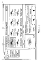
- the cooling device management system 100 which is shown in Fig. 1 is a system for managing an air conditioning device 10 which is a cooling device which is disposed in a building 90.
- the cooling device management system 100 is a system which monitors and controls the air conditioning device 10 at a location which is separate from the location where the air conditioning device 10 is disposed.
- the cooling device management system 100 is a system for detecting the presence or absence of coolant leaks in the air conditioning device 10 at a location which is separate from the location where the air conditioning device 10 is disposed.
- the cooling device management system 100 is mainly configured from the air conditioning device 10, a controller 20, and a remote management device 30.
- Each of the air conditioning devices 10 includes one unit of an outdoor unit 11 and a plurality of indoor units 12. In the present embodiment, a plurality of the air conditioning devices 10 are disposed in the building 90.
- the controller 20 has a function of monitoring and controlling the air conditioning devices 10.
- the controller 20 is disposed in a management personnel room or the like in the building 90.
- the plurality of the air conditioning devices 10 are connected to the controller 20.
- the controller 20 and the air conditioning devices 10 are connected using dedicated wiring 70.
- the controller 20 controls a plurality of the outdoor units 11 and the plurality of the indoor units 12 which are connected to each of the outdoor units 11.
- the remote management device 30 is a server which is provided in a remote management center 13 which is positioned at a distance from the building 90.
- the remote management device 30 is able to connect with the controller 20 through an Internet 60.
- instructions (detection control instructions) for executing a coolant leakage detection driving mode is transmitted from either of the controller 20 or the remote management device 30, which are disposed at locations which are separated from the outdoor units 11, with regard to the air conditioning devices 10.
- the coolant leakage detection driving mode is a driving mode for detecting the presence or absence of coolant leaks.
- all of the indoor units 12 which are connected to the outdoor units 11 which are the targets are compulsorily driven in a mode for cooling for a specific period of time (for example, 110 minutes).
- the state of the coolant which circulates in a coolant circuit is stabilized and the amount of coolant in the coolant circuit is calculated as described in Japanese Unexamined Patent Application Publication No. 2007-163099 , WO2007/069578 , EP1970652A1 , and the like by compulsorily driving to cool for a specific period of time
- the air conditioning device 10 includes one unit of the outdoor unit 11 and the plurality of indoor units 12. It is possible for a maximum of 64 units of the indoor units 12 to be connected with one unit of the outdoor unit 11. That is, one of the coolant circuits are configured from one unit of the outdoor unit 11 and a maximum of 64 units of the indoor units 12.
- the air conditioning device 10 has an overall configuration as the coolant circuit which is configured from a compressor, a heat exchanger, and the like which are not shown in the diagrams. Simple R32 coolant flows in the coolant circuit in the air conditioning device 10 according to the present embodiment.
- the outdoor unit 11 and the indoor units 12 are connected using the dedicated wiring 70 and coolant piping. As shown in Fig.
- a remote controller 12c which receives inputting of operations with regard to each of the indoor units 12 is separately attached to the air conditioning device 10.
- the remote controller 12c has an input section and a display section.
- the input section receives control instructions with regard to each of the indoor units 12.
- the display section displays the driving situation of each of the indoor units 12.
- Information on performing driving in either of driving for cooling, driving for heating, undergoing inspection, or coolant leakage detection driving and information such as the settings for temperature, the amount of air flow, and the air flow direction are included as the driving situation which is displayed on the display section of the remote controller 12c. That is, the remote controller 12c also functions as a display section for the air conditioning device 10 which displays each type of information on the air conditioning device 10.
- the input section invalidates input which is related to specific operations until cancelation instructions are received after restriction instructions which will be described later are received from the controller 20.
- the specific operations are, for example, an operation of turning the power off, an operation of stopping driving, an operation of changing the driving mode, and the like.
- the indoor unit 12 mainly has the communication section 12a and the control section 12b.
- the communication section 12a is an interface for performing communication with the outdoor unit 11.
- the control section 12b receives a control signal from the outdoor unit 11 through the communication section 12a and each section which configures the indoor unit 12 is run based on the control signal.
- the control section 12b sends data which relates to the driving state (the state of on or off, the suction temperature, and the like) with regard to the outdoor unit 11 through the control section 12a.
- the outdoor unit 11 mainly has a communication section 11 a, an output section 11b, an input section 11c, a memory section 11d, and a control section (an operation input section) 11e.
- the communication section 11 a is an interface for performing communication with the indoor units 12 as described above. In addition, the communication section 11a is an interface for performing communication with the controller 20.
- the output section 11b is a plurality of LEDs which flash or are turned off.
- the LEDs are provided on a print substrate which is not shown in the diagrams.
- the output section 11b expresses the state of the air conditioning device 10 by flashing and turning off the plurality of LEDs.
- the state of the air conditioning device 10 which is indicated by the output section 11b is the presence or absence of abnormalities being generated in the outdoor unit 11, the type of abnormalities which are generated, the presence or absence of coolant leaks, and the like. That is, the output section 11b changes the way in which the LED flash or are turned off according to the state of the air conditioning device 10.
- the input section 11c is a button for receiving instructions for executing the coolant leakage detection driving from a maintenance worker.
- the output section 11c is a button which is directly operated by a maintenance worker travelling to the location where the air conditioning device 10 is disposed.
- the button is provided on the casing of the outdoor unit 11 which is not shown in the diagrams.
- the coolant leakage detection driving is executed by the control section 11e when instructions for executing the coolant leakage detection driving are received using the input section 11 c.
- the memory section 11d is mainly configured from a ROM, a RAM, and a hard disk. Programs which are able to be executed by being read out by the control section 11e which will be described later are stored in the memory section 11d. In addition, driving data, initial amount data, and current amount data are stored in the memory section 11d as shown in Fig. 2 .
- Driving data for the outdoor unit 11 and driving data for the indoor units 12 are included in the driving data.
- the driving data for the outdoor unit 11 has the meaning of values for the state of the various types of components which are included in the outdoor unit 11, and the outdoor temperature and outdoor humidity which are detected by the outdoor unit 11.
- the values for the state of the various types of components which are included in the outdoor unit 11 are, for example, the frequency of the compressor, the number of rotations of an outdoor fan, and the temperature and pressure of the coolant at specific positions in the coolant circuit.
- Parameters for driving the indoor units 12, the indoor temperature, the indoor humidity, and values for the state of the various types of components which are included in the indoor unit 12 are included in the driving data for the indoor units 12.
- the parameters for driving the indoor unit 12 are, for example, the state of starting or stopping the indoor units 12, the settings for temperature, the settings for humidity, the settings for air flow, the settings for direction of air flow, and the driving modes such as cooling, heating, ventilating, dehumidifying, and the like.
- the values for the state of the various types of components which are included in the indoor unit 12 are, for example, the number of rotations of an indoor fan and the temperature and pressure of the coolant at specific positions in the coolant circuit.
- data where it is possible to identify whether the air conditioning device 10 is in any of the states of driving, undergoing inspection, or emergency shutdown and data where it is possible to identify normal or abnormal with regard to the air conditioning device 10 are included in the driving data.
- the initial amount data is data which relates to the amount of coolant which is filled using automatic driving for filling coolant which is carried out in the initial arrangement of the air conditioning device 10 and is data which relates to the amount of coolant which is filled into the coolant circuit according to the configuration of the air conditioning device 10 at the initial arrangement of the air conditioning device 10.
- the initial amount data is the amount of coolant which is a reference (reference amount of coolant).
- the initial amount data is stored in the memory section 11 d as initial amount data along with the date and time of when the first automatic driving for filling coolant is carried out.
- the current amount data is data which relates to the amount of coolant which is filled into the coolant circuit at the current point in time.
- the current amount data is data which is acquired by carrying out the coolant leakage detection driving.
- the current amount data is the latest data which relates to the amount of coolant which is acquired by executing the latest coolant leakage detection driving.
- the current amount data is stored in the memory section 11d as current amount data along with the date and time of when the coolant leakage detection driving is carried out after the coolant leakage detection driving is carried out.
- information which relates to errors which are generated during executing of the coolant leakage detection driving may be included in the memory section 11d.
- the control section 11e is mainly configured from a CPU.
- the control section 11e reads out and executes programs which are stored in the memory section 11d.
- the control section 11e functions as an operation inputting section.
- the operation inputting section receives various types of control instructions which are sent from the controller 20.
- the control section 11e runs the air conditioning device 10 (that is, the outdoor unit 11 and the indoor units 12) based on control instructions which are received using the operation inputting section.
- the operation inputting section invalidates input which is related to specific operations until cancelation instructions are received after restriction instructions which will be described later are received from the controller 20.
- the specific operations are, for example, an operation of turning the power off, an operation of stopping driving, an operation of changing the driving mode, and the like in the same manner as the content described above.
- control section 11e runs each of the sections which configures the outdoor unit 11 according to control instructions (the state of starting or stopping the indoor units 12, the settings for temperature, the settings for humidity, the settings for air flow, the settings for direction of air flow, and the driving mode) which are sent from the controller 20.
- control instructions the state of starting or stopping the indoor units 12, the settings for temperature, the settings for humidity, the settings for air flow, the settings for direction of air flow, and the driving mode
- control section 11e generates control instructions for performing adjusting of the frequency of the compressor, the number of rotations of a fan, the opening of various valve, and the like.
- control section 11e acquires the driving data from the indoor units 12 according to control instructions which are sent from the controller 20 and transmits the driving data on the indoor units 12 which is acquired to the controller 20.
- control section 11e acquires the driving data on the outdoor unit 11 from the memory section 11d and transmits the driving data on the outdoor units 11 which is acquired to the controller 20 according to control instructions which are sent from the controller 20.
- control section 11e executes the coolant leakage detection driving based on control instructions which are received using the input section 11c or control instructions (detection control instructions) which is sent from the controller 20. That is, driving for cooling is compulsorily carried out with regard to all of the indoor units 12 which configure the same coolant system of the outdoor unit 11, the state of the coolant which circulates in the coolant circuit is stabilized, and the amount of coolant in the coolant circuit is calculated.
- the control section 11e stores the current amount of coolant which is acquired using this calculation (the current amount), the date and time when the coolant leakage detection driving is executed, errors which are generated in the coolant leakage detection driving, and the like in the memory section 11d.
- the controller 20 has a function of monitoring and controlling the air conditioning device 10 as described above.
- the controller 20 is mainly configured from a communication section 21, a display section 22, an input section (a coolant leakage detection schedule setting section and a normal schedule setting section) 23, a memory section 24, and a control section 25.
- the communication section 21 is an interface where it is possible for the controller 20 to connect with the Internet 60 and the air conditioning device 10.
- the display section 22 is mainly configured from a display.
- the input section 23 receives various types of settings with regard to the controller 20.
- the input section 23 is configured from a touch panel which covers the display.
- the display section 22 displays a management screen 221 for the air conditioning device 10 which is mainly used by a user (refer to Fig. 4 ), screens 222 and 223 which relate to the coolant leakage detection driving and which are mainly used by a maintenance worker (refer to Fig. 5 and Fig. 6 ), and detection results of the coolant leakage detection driving (refer to Fig. 7 ).
- Driving information for each of the indoor units 12 is displayed in the management screen 221.
- states such as stopping, driving, abnormality, communication abnormality, and the like are included in the driving information which is displayed on the management screen 221.
- the driving information is stored in the memory section 24 which will be described later.
- buttons B1 to B7 for performing control of each of the indoor units 11 are provided in the management screen 221.
- the button B1 is a button for driving of all of the indoor units 12 all together (all driving button).
- the button B2 is a button for stopping of all of the indoor units 12 all together (all stopping button).
- the button B3 is a button for individual driving of the indoor units 12 (driving button).
- the button B4 is a button for individual stopping of the indoor units 12 (stopping button).
- the button B5 is a button for setting the specifics (driving mode, temperature, humidity, air flow, air flow direction, and the like) of the operations of each of the indoor units 12 (specifics button).
- the button B6 is a button for setting the driving schedule (normal schedule) for the indoor units 12 (driving schedule setting button).
- the driving schedule is a schedule which relates to the timing when the driving of the indoor units 12 is started, the timing when the driving of the indoor units 12 is stopped, and the driving content.
- the management screen 221 moves to the driving schedule setting screen which is not shown in the diagram due to any of the indoor units 12 being selected from the indoor units 12 which are displayed on the management screen and the driving schedule setting button B6 being pressed.
- the button B7 is a button which is used by a maintenance worker. When the button B7 is pressed, a screen (which is not shown in the diagrams) for inputting a specific ID or the like is displayed. When the specific ID is input into this screen, an operations screen for maintenance workers (refer to Fig. 5 and Fig. 6 ) is displayed.
- a screen which relates to the coolant leakage detection driving is included in the operations screen for maintenance workers.
- the screen (detection driving start screen) 222 for starting the coolant leakage detection driving as shown in Fig. 5 and the screen (detection schedule setting screen) 223 which receives inputting of settings for the schedule for the coolant leakage detection driving (detection schedule) as shown in Fig. 6 are included in the screen which relates to the coolant leakage detection driving.
- the detection schedule is a schedule which relates to the date and time when the coolant leakage detection driving mode is executed.
- a region R1 which displays a target for management and buttons B11 to B16 are provided in the detection driving start screen 222.
- the names of the outdoor units 11 which are to be the targets for management (for example, outdoor units 1 to 5), management addresses, the number of the indoor units 12 which configure the same coolant system in each of the outdoor units 11, the coolant filling situation, and the detection schedule (starting date and time) are displayed in the region R1.
- the detection schedule which is displayed in the region R1 is the date and time for the earliest out of the detection schedule which is set.
- the button B11 is a button which is used for newly registering a schedule for the coolant leakage detection driving (registration button).
- the button B12 is a button for starting the coolant leakage detection driving (detection start button).
- the button B13 is a button for stopping the coolant leakage detection driving (detection stop button).
- the button B 14 is a button for setting a schedule for the coolant leakage detection driving (detection schedule setting button).
- the detection schedule setting button B14 is pressed, the detection driving start screen 222 is switched to the detection schedule setting screen 223 (refer to Fig. 6 ).
- the detection schedule setting screen 223 is configured so that it is possible for four schedules to be set with regard to each of the outdoor units 11. In other words, it is possible for four starting dates and times for the coolant leakage detection driving with regard to the coolant circuit which includes each of the outdoor units 11 to be input into the detection schedule setting screen 223.
- the button B 15 is a button for outputting the detection result which is acquired using the coolant leakage detection driving in CSV format (detection result output button).
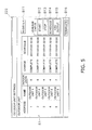
- the detection result output button B15 When the detection result output button B15 is pressed, information which relates to the date and time when the coolant leakage detection driving is carried out and the coolant leakage amount is output in CSV format as shown in Fig. 7 with regard to all of the outdoor units 11 which are registered. Information which relates to the coolant leakage detection driving up to 100 times in the past is shown for each of the outdoor units 11 in the detection results.
- the button B16 is a button for terminating the settings which relate to the coolant leakage detection driving (terminate button). By pressing the terminate button B16, the detection driving start screen 222 is switched to the management screen 221.
- buttons B1 to B7 in the management screen 221 are invalidated when the coolant leakage detection driving which will be described later starts.
- the various types of settings which are input using the input section 23 are stored in the memory section 24 which will be described later.
- the memory section 24 is mainly configured from a ROM, a RAM, and a hard disk. Programs which are able to be executed by being read out by the control section 25 which will be described later are stored in the memory section 24.
- the memory section 24 mainly has a driving data storage region 24a, a driving schedule storage region 24b, a detection schedule storage region 24c, and a detection related data storage region 24d.
- Driving data on the air conditioning device 10 which is acquired using an acquiring section 25a which will be described later is stored in the driving data storage region 24a.
- Driving data on the outdoor unit 11 and driving data on the indoor units 12 are included in the driving data as described above.
- the values for the state of the various types of components which are included in the outdoor unit 11, and the outdoor temperature and outdoor humidity which are detected by the outdoor unit 11 are included in the driving data for the outdoor unit 11, and the parameters for driving the indoor units 12, the indoor temperature, the indoor humidity, and values for the state of the various types of components which are included in the indoor unit 12 are included in the driving data for the indoor units 12.
- the driving schedule which is input through the input section 23 and the driving schedule which is sent from the remote management device 30 are stored in the driving schedule storage region 24b.
- the driving schedule is a schedule which relates to the timing when the driving of the indoor units 12 is started, the timing when the driving of the indoor units 12 is stopped, and the driving content.
- the driving schedule which is stored in the driving schedule storage region 24b is overwritten with a new driving schedule which is newly set.
- the detection schedule which is input through the input section 23 and the detection schedule which is sent from the remote management device 30 are stored in the detection schedule storage region 24c.
- the detection schedule is a schedule which relates to the date and time when the coolant leakage detection driving mode is carried out as described above.
- the detection schedule which is stored in the detection schedule storage region 24c is also overwritten with a detection schedule which is newly set.
- the initial amount data and the current amount data which are acquired using the acquiring section 25a which will be described later are stored in the detection related data storage region 24d.
- the initial amount data is data which relates to the amount of coolant which is acquired using automatic driving for filling coolant which is carried out in the initial arrangement of the air conditioning device 10 as described above.
- the current amount data is data which relates to the amount of coolant which is acquired using the coolant leakage detection driving and is data which relates to the amount of coolant which is filled into the coolant circuit at the current point in time as described above.
- determination history of the detection feasibility conditions which are determined using the detection feasibility determining section 25c which will be described later is also stored in the detection related data storage region 24d.
- Information which relates to errors which are generated prior to executing of the coolant leakage detection driving is included in the determination history.
- Information which relates to errors which are generated during executing of the coolant leakage detection driving may be included in the detection related data storage region 24d.
- Information which is acquired over a specific interval of time (an interval of one minute in the present embodiment) using the acquiring section 25a is included in the information which related to the errors.
- results which are determined using a leakage determining section 25d which will be described later are stored in the detection related data storage region 24d to be associated with the date and time when the coolant leakage detection driving is executed (refer to Fig. 7 ).
- the control section 25 is mainly configured from a CPU and is mainly run as the acquiring section (reception section) 25a, a control instructions generating section (schedule executing section) 25b, the detection feasibility determining section 25c, the leakage determining section 25d, and a transmission section 25e by reading out and executing programs which are stored in the memory section 24.
- the acquiring section 25a collects the driving data for each of the air conditioning devices 10 over a specific interval or time (an interval of one minute in the present embodiment). In detail, the acquiring section 25a acquires the driving data on the outdoor units 11 from the control section 11e of each of the outdoor units 11. In addition, the acquiring section 25a collects the driving data on the indoor units 12 through the outdoor units 11. The driving data which is collected by the acquiring section 25a is stored in the driving data storage region 24a.
- the acquiring section 25a acquires the initial amount data from the air conditioning device 10.
- the acquiring section 25a requests the initial amount data which is stored in the storage section 11d with regard to the outdoor units 11.
- the initial amount data which is acquired using the acquiring section 25a is stored in the detection related data storage region 24d.
- the acquiring section 25a acquires the current amount data from the air conditioning device 10 over a specific period of time (110 minutes in the present embodiment).
- the control section 11e of the outdoor unit 11 calculates the amount of coolant in the coolant circuit over 110 minutes and the acquiring section 25a acquires the results which are calculated (the current amount data).
- the current amount data which is acquired using the acquiring section 25a is stored in the detection related data storage region 24d.
- the control instructions generating section 25b generates various types of control instructions which are executed by the air conditioning device 10 based on the settings which are received using the input section 23 and the settings which are received using the remote management device 30.
- An immediate schedule, the driving schedule, and the detection schedule are included in the settings which are received using the input section 23 and settings which are received using the remote management device 30.
- the immediate schedule is settings which are immediately run with conditions which are desired by a user.
- the control instructions generating section 25b generates control instructions with priority given to control instructions based on the detection schedule over the driving schedule. In other words, the control instructions generating section 25b generates control instructions with priority given to control instructions (detection control instructions) for executing the coolant leakage detection driving with regard to the air conditioning device 10 in a case where the detection schedule which is to be executed is stored.
- the detection control instructions are instructions for all of the indoor units 12 which are included in the air conditioning device 10 to be compulsorily driven to cool and for the current amount data to be collected.
- control instructions generating section 25b generates control instructions for interrupting (or cancelling) controlling which is based on the driving schedule (interruption instructions) and transfers the interruption instructions to the transmission section 25e in a case where controlling which is based on the driving schedule is being performed in the air conditioning device 10 when control instructions which are based on the detection schedule are generated. Furthermore, the control instructions generating section 25b generates control instructions for restarting controlling which is based on the driving schedule which is interrupted (restarting instructions) and transfers the restarting instructions to the transmission section 25e when the coolant leakage detection driving is completed and detection results are acquired after the interruption instructions are generated.
- control instructions generating section 25b transfers the detection control instructions to the transmission section 25e after the detection feasibility determining section 25c which will be described later determines that the coolant leakage detection driving is possible.
- the detection control instructions are transmitted to the air conditioning device 10 using the transmission section 25e which will be described later.
- the detection control instructions are not transmitted to the transmission section 25e in a case where the detection feasibility determining section 25c determines that the coolant leakage detection driving is not possible.
- control instructions generating section 25b generates instructions for performing a specific display (display instructions) on the display section of the air conditioning device 10 (any or all of the display section of the remote controller 12c, the display section 22 of the controller 22, and a display section 32 of the remote management device 30) when the detection control instructions are transferred to the transmission section 25e and also transfers the display instructions to the transmission section 25e.
- the specific display is a display which accompanies the coolant leakage detection driving and is a display which indicates that the air conditioning device 10 is carrying out the coolant leakage detection driving. That is, the air conditioning device 10 shows the display that the coolant leakage detection driving is being carried out on the display section along with carrying out the coolant leakage detection driving when the detection control instructions are transmitted to the air conditioning device 10 using the transmission section 25e.
- control instructions generating section 25b further generates restriction instructions when the detection control instructions are transferred to the transmission section 25e and transfers the restriction instructions to the transmission section 25e at the same time.
- the restriction instructions are instructions for carrying out restrictions so that the operations inputting section of the air conditioning device 10 does not receive inputting of the specific operations.
- the specific operations are, for example, an operation of turning the power off, an operation of stopping driving, an operation of changing the driving mode, and the like as described above.
- control instructions generating section 25b generates instructions for terminating the specific display (display termination instructions) and instructions for cancelling the restricting of inputting operations (cancellation instructions) when acquiring of the current amount data using the acquiring section 25a is completed.
- the display termination instructions and the cancellation instructions are also transferred to the transmission section 25e.
- the detection feasibility determining section 25c determines the feasibility of the coolant leakage detection driving in the air conditioning device 10 which is the target based on specific detection feasibility conditions when the detection control instructions are generated using the control instructions generating section 25b as described above. In other words, the detection feasibility determining section 25c confirms that there is not a state where the coolant leakage detection driving is not possible (inappropriate state) in the air conditioning device 10 which is the target of the coolant leakage detection driving.
- the specific detection feasibility conditions are conditions which relate to the state of communications with the air conditioning device 10 and the driving state of the air conditioning device 10. In detail, the specific detection feasibility conditions are conditions which relate to the presence or absence of communication abnormalities, the coolant filling state, and the driving state of the air conditioning device 10 (undergoing inspection, in emergency shutdown, or abnormality generated).
- the detection feasibility determining section 25c determines the presence or absence of communication abnormalities between the controller 20 and the outdoor unit 11. In detail, the detection feasibility determining section 25c performs communication a specific number of times (four times in the present embodiment) with regard to the outdoor unit 11 and it is determined that the coolant leakage detection driving is not possible in a case where communication is not established within the specific number of times.
- the detection feasibility determining section 25c determines the coolant filling state in the coolant circuit based on the initial amount data which is stored in the detection related data storage region 24d. In detail, the detection feasibility determining section 25c determines whether or not the amount of the coolant filled in the air conditioning device 10 which is a target for the coolant leakage detection driving is not "0". The detection feasibility determining section 25c determines that the coolant leakage detection driving is not possible in a case where the value which indicates the initial amount (the amount of coolant which is initially filled into the coolant circuit) is "0".
- the detection feasibility determining section 25c determines whether or not the air conditioning device 10 is being driven normally based on the driving data which is stored in the driving date storage region 24a. In detail, the detection feasibility determining section 25c determines whether the air conditioning device 10 is undergoing inspection, is in emergency shutdown, or an abnormality has been generated. In more detail, the detection feasibility determining section 25c determines whether the outdoor unit 11 and the indoor units 12 which configure the same coolant circuit as the outdoor unit 11 are undergoing inspection, are in emergency shutdown, or an abnormality has been generated.
- the detection feasibility determining section 25c determines that the coolant leakage detection driving is not possible in a case where any device is undergoing inspection, any device is in emergency shutdown, or an abnormality has been generated in any device among the devices out of the outdoor unit 11 and the indoor units 12 which configure the coolant circuit.
- the detection feasibility determining section 25c stores the determination history of the detection feasibility conditions in the detection related data storage region 24d.
- the detection feasibility determining section 25c displays a dialogue which prompts confirming of executing of the coolant leakage detection driving on the display section 22 (refer to Fig. 8 ) before determining the feasibility of the coolant leakage detection driving in a case where the detection control instructions which are generated by the control instruction generating section 25b are based on the immediate schedule.
- the detection feasibility determining section 25c displays a dialogue which shows the reasoning for this on the display section 22 (refer to Fig. 9 ).
- the results which are determined using the leakage determining section 25d are stored in the detection related data storage region 24d to be associated with the date and time when the coolant leakage detection driving is executed (refer to Fig. 7 ).
- the transmission section 25e transmits various types of instructions which are set by the controller 20 and various types of instructions which are sent from the remote management device 30 to the air conditioning device 10.
- the transmission section 25e transmits the control instructions which are generated by the control instructions generating section 25b and the control instructions which are sent from the remote management device 30 with regard to the air conditioning device 10.
- the transmission section 25e transmits the driving data which is stored in the driving data storage region 24a to the remote management device 30 in specific intervals of time (every 30 minutes in the present embodiment).
- the remote management device 30 is a server computer which is mainly configured from a communication section 31, the display section 32, an input section (a coolant leakage detection schedule setting section and a normal schedule setting section) 33, a memory section 34, and a control section (a reception section, a transmission section, and a schedule executing section) 35.
- the remote management device 30 has a function of monitoring and controlling the air conditioning device 10 through the controller 20.
- the remote management device 30 according to the present embodiment executes the coolant leakage detection driving in the air conditioning device 10 through the controller 20.
- the communication section 31 is a network interface where it is possible for the remote management device 30 to connect with the Internet 60.
- the display section 32 is mainly configured from a display.
- a management screen 321 for the air conditioning device 10 is displayed on the display section 32 as shown in Fig. 11 .
- the driving data for the air conditioning device 10 is shown on the management screen 321. It is possible to monitor the driving situation of the air conditioning device 10 and to control the air conditioning device 10 from a distance from the building 90 by performing setting of the air conditioning device 10 using the management screen 321.
- buttons B31 and B32 are provided in the management screen 321 as shown in Fig. 11 .
- the button B31 is a button for setting the driving schedule (driving schedule setting button).
- the button B32 is a button for setting the detection schedule.
- the management screen 321 is switched to a screen which relates to the coolant leakage detection driving.
- the screen which relates to the coolant leakage detection driving is the same screen as the screen which is displayed in the display section 22 of the controller 20.
- the screen (detection driving start screen) 222 for starting the coolant leakage detection driving as shown in Fig. 5 and the screen (detection schedule setting screen) 223 for setting the schedule for the coolant leakage detection driving (detection schedule) as shown in Fig. 6 are included in the screen which relates to the coolant leakage detection driving.
- the input section 33 is mainly configured from a mouse and a keyboard.
- the memory section 34 is mainly configured from a ROM, a RAM, and a hard disk. Programs which are able to be executed by being read out by the control section 35 which will be described later are stored in the memory section 34.
- the memory section 34 stores the driving data and the detection related data for the air conditioning device 10 which the control section 35 which will be described later acquires through the controller 20.
- the memory section 34 stores various types of settings (the immediate schedule, settings for the driving schedule, and settings for the detection schedule) which are input through the input section 33.
- various types of information the driving data, various types of settings, and the like for the air conditioning device 10.
- the control section 35 is mainly configured from a CPU.
- the control section 35 reads out and executes programs which are stored in the memory section 34.
- the control section 35 generates the control instructions based on the settings (the immediate schedule, settings for the driving schedule, and settings for the detection schedule) which are input through the input section 33.
- the control section 35 transmits the control instructions to the controller 20 through the Internet 60.
- control section 35 acquires various types of information (the driving data, various types of settings, and the like) from the controller 20 and stores the information which is acquired in the memory section 34.
- Fig. 12 illustrates a process flow according to the coolant leakage detection driving which is based on the immediate schedule.
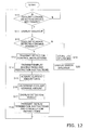
- Fig. 13 illustrates a process flow according to the coolant leakage detection driving which is based on the detection schedule.
- Fig. 14 illustrates a process flow where the detection schedule is prioritized with regard to the driving schedule.
- the immediate schedule is settings which are received using the input section 23 of the controller 20 or the input section 33 of the remote management device 30.
- step S10 it is determined whether or not there is a request for the coolant leakage detection driving. There is waiting in step S10 until there is a request for the coolant leakage detection driving and the process flow proceeds to step S 11 when there is a request.
- step S11 a dialogue which prompts confirming of executing of the coolant leakage detection driving is displayed (refer to Fig. 8 ).
- the dialogue is displayed in the device where the immediate schedule of the coolant leakage detection driving is set. That is, the dialogue is displayed in the display section 22 of the controller 20 if the immediate schedule is set using the controller 20, and the dialogue is displayed in the display section 32 of the remote management device 30 if the immediate schedule is set using the remote management device 30.
- step S12 feasibility of the coolant leakage detection driving is determined.
- the feasibility of the coolant leakage detection driving is determined based on the detection feasibility conditions. In detail, the presence or absence of communication abnormalities between the controller 20 and the air conditioning device 10 (the outdoor unit 11) which is the target of the coolant leakage detection driving, whether or not the coolant is filled in the coolant circuit of the air conditioning device 10 which is the target, whether or not the air conditioning device 10 which is the target is undergoing inspection, whether or not the air conditioning device 10 which is the target is in emergency shutdown, whether or not an abnormality has occurred in the air conditioning device 10 which is the target are each determined.
- step S12 the process flow proceeds to step S13 when it is determined that the coolant leakage detection driving is possible.
- step S 13 instructions for carrying out the coolant leakage detection driving (detection control instructions) are transmitted to the air conditioning device 10.
- the air conditioning device 10 which receives the detection control instructions switches to the coolant leakage detection driving mode, performs compulsorily driving for cooling, and starts to collect the current amount data.
- step S 14 instructions for carrying out the coolant leakage detection driving (detection control instructions) are transmitted to the air conditioning device 10.
- the air conditioning device 10 which receives the detection control instructions switches to the coolant leakage detection driving mode, performs compulsorily driving for cooling, and starts to collect the current amount data.
- step S 14 instructions for carrying out the coolant leakage detection driving
- step S 14 the display instructions and the restriction instructions are sent to the air conditioning device 10.
- the display instructions are instructions for performing the specific display in the air conditioning device 10 as described above.
- the specific display is a display which accompanies the coolant leakage detection driving and is a display which indicates that the air conditioning device 10 is carrying out the coolant leakage detection driving.
- the restriction instructions are instructions for carrying out restrictions so that inputting of the specific operations are not received by the air conditioning device 10 as described above. Thereby, that the coolant leakage detection driving is being carried out is shown in the air conditioning device 10 and there is a state where inputting of the specific operations are not received from the outside. After this, the process flow proceeds to step S15.
- step S 15 the current amount data is acquired from the air conditioning device 10 where the coolant leakage detection driving is carried out.
- data which relates to the amount of coolant which is currently included in the coolant circuit of the air conditioning device 10 (current amount data) is acquired from the control section 11e of the outdoor unit 11.
- the current amount data which is collected by the acquiring section 25a is stored in the detection related data storage region 24d. After this, the process flow proceeds to step S16.
- step S16 the coolant leakage amount is determined.
- the determination result (the detection result) in step S16 is stored in the detection related data storage region 24d to be associated with the date and time when the coolant leakage detection driving is executed (refer to Fig. 7 ).
- the process flow proceeds to step S 17.
- step S17 the detection results are displayed on the display sections 22 and 32.
- the detection results are displayed on the device where there is the request for the coolant leakage detection driving. That is, the detection results are displayed in the display section 22 of the controller 20 if the request for the coolant leakage detection driving is generated using the controller 20 and the detection results are displayed in the display section 32 of the remote management device 30 if the request for the coolant leakage detection driving is generated using the remote management device 30.
- the process flow proceeds to step S18.
- step S18 the display termination instructions and the cancellation instructions are transmitted to the air conditioning device 10.
- the display termination instructions are instructions for terminating the displaying of the specific display and the cancellation instructions are instructions for cancelling the restrictions on inputting. Thereby, the specific display disappears and the restriction on inputting are cancelled in the air conditioning device 10.
- step S12 determines whether the coolant leakage detection driving is not possible. If it is determined in step S12 that the coolant leakage detection driving is not possible, the process flow proceeds to step S 19. In step S 19, a log on items which are determined to be not possible (errors) is stored in the detection related data storage region. After this, the process flow proceeds to step S20.
- step S20 an error dialogue such as shown in Fig. 9 is displayed on the display sections 22 and 32.
- the error dialogue is also displayed on the device where the immediate schedule for the coolant leakage detection driving is set. That is, the error dialogue is displayed in the display section 22 of the controller 20 if the immediate schedule is set using the controller 20, and the error dialogue is displayed in the display section 32 of the remote management device 30 if the immediate schedule is set using the remote management device 30.
- the detection schedule is also settings which are received using the input section 23 of the controller 20 or the input section 33 of the remote management device 30.
- step S21 it is determined whether or not the coolant leakage detection driving is necessary based on the detection schedule. There is waiting in step S21 until the coolant leakage detection driving is necessary, and the process flow proceeds to step S22 when the coolant leakage detection driving is necessary.
- step S22 the feasibility of the coolant leakage detection driving is determined.
- the feasibility of the coolant leakage detection driving is determined based on the detection feasibility conditions. In detail, the presence or absence of communication abnormalities between the controller 20 and the air conditioning device 10 (the outdoor unit 11) which is the target of the coolant leakage detection driving, whether or not the coolant is filled in the coolant circuit of the air conditioning device 10 which is the target, whether or not the air conditioning device 10 which is the target is undergoing inspection, whether or not the air conditioning device 10 which is the target is in emergency shutdown, whether or not an abnormality has occurred in the air conditioning device 10 which is the target are each determined.
- the process flow proceeds to step S23 when it is determined that the coolant leakage detection driving is possible.
- step S23 instructions for carrying out the coolant leakage detection driving (detection control instructions) are transmitted to the air conditioning device 10.
- the air conditioning device 10 which receives the detection control instructions switches to the coolant leakage detection driving mode, all of the indoor units 12 perform compulsorily driving for cooling, and collecting of the current amount data is started.
- step S24 instructions for carrying out the coolant leakage detection driving
- step S24 the display instructions and the restriction instructions are sent to the air conditioning device 10. Thereby, that the coolant leakage detection driving is being carried out is shown in the air conditioning device 10 and there is a state where inputting of the specific operations are not received from the outside.
- step S25 the process flow proceeds to step S25.
- step S25 the current amount data is acquired from the air conditioning device 10 where the coolant leakage detection driving is carried out.
- data which relates to the amount of coolant which is currently included in the coolant circuit of the air conditioning device 10 (current amount data) is acquired from the control section 11e of the outdoor unit 11.
- the current amount data which is collected by the acquiring section 25a is stored in the detection related data storage region 24d. After this, the process flow proceeds to step S26.
- step S26 the coolant leakage amount is determined.
- the determination result (the detection result) in step S26 is stored in the detection related data storage region 24d to be associated with the date and time when the coolant leakage detection driving is executed (refer to Fig. 7 ).
- the detection results which are stored in the detection related data storage region are output in CSV format by receiving input using the button B15 in the detection driving start screen 222.
- step S27 the display termination instructions and the cancellation instructions are transmitted to the air conditioning device 10.
- the display termination instructions are instructions for terminating the displaying of the specific display and the cancellation instructions are instructions for cancelling the restrictions on inputting. Thereby, the specific display disappears and the restrictions on inputting are cancelled in the air conditioning device 10.
- step S22 if it is determined in step S22 that the coolant leakage detection driving is not possible, a log on items which are determined to be not possible (errors) is stored in the detection related data storage region in step S28.
- the log which is stored in the detection related data storage region is output in CSV format by receiving input using the button B 15 in the detection driving start screen 222.
- step S31 whether or not there is the detection schedule is determined.
- the process flow proceeds to step S32 in a case where there is the detection schedule in step S 31.
- step S32 whether or not there is the driving schedule which is currently being executed is determined.
- the process flow proceeds to step S33 in a case where there is the driving schedule which is currently being executed in step S32.
- step S34 in a case where there is no driving schedule which is currently being executed in step S 32.
- step S33 the driving schedule being executed is interrupted. In other words, the control content of the air conditioning device 10 which is based on the driving schedule is cancelled and the air conditioning device 10 is stopped. After this, the process flow proceeds to step S34.
- step S34 the detection control instructions are transmitted. That is, the driving leakage detection driving is executed in the air conditioning device 10. After this, the process flow proceeds to step S35.
- step S35 whether or not the driving leakage detection driving is completed is determined. There is waiting in step S35 until the coolant leakage detection driving is completed, and the process flow proceeds to step S36 when the coolant leakage detection driving is completed.
- step S36 whether or not there is the driving schedule which is being interrupted is determined.
- the process flow returns to step S31 in a case where there is no driving schedule which is being interrupted in step S36.
- the process flow proceeds to step S37 in a case where there is the driving schedule which is being interrupted in step S36.
- step S3 7 controlling of the air conditioning device 10 which is based on the driving schedule which is being interrupted is restarted. After this, the process flow proceeds to step S38 and returns to step S31 in a case where the driving schedule which is completed.
- the cooling device management system 100 it is possible to set the detection schedule according to the coolant leakage detection driving of the air conditioning device 10 using the controller 20 or the remote management device 30 which are at locations which are separated from the air conditioning device 10.
- the air conditioning device 10 executes the coolant leakage detection driving based on the detection schedule. Thereby, it is possible to carry out the coolant leakage detection driving with regard to the air conditioning device 10 without a maintenance worker travelling to the location where the air conditioning device 10 is disposed. Accordingly, it is possible to reduce the burden and costs even in a case where there is an increase in the number of the air conditioning devices 10 which are the targets for carrying out the coolant leakage detection driving.
- the display instructions are transmitted along with the instructions to carry out the coolant leakage detection driving (the detection control instructions) being transmitted to the air conditioning device 10.
- the display instructions are instructions for performing the specific display which indicates that the coolant leakage detection driving is being carried out in the display section (which is not shown in the diagrams) of the air conditioning device 10. Thereby, it is possible to notify users of the cooling device that the cooling device is carrying out the coolant leakage detection driving.
- the restriction instructions are transmitted along with the instructions to carry out the coolant leakage detection driving (the detection control instructions) being transmitted to the air conditioning device 10.
- the restriction instructions are instructions for carrying out restrictions so that inputting of the specific operations are not received in the air conditioning device 10. Thereby, there is a state in the air conditioning device 10 where inputting of the specific operations is not received from the outside while the coolant leakage detection driving is being carried out. Thereby, it is possible to acquire accurate detection results since it is possible to reliably execute and complete the coolant leakage detection driving.
- the state of communication with the air conditioning device 10, the driving state of the air conditioning device 10, and the like are determined before the coolant leakage detection driving is carried out with regard to the air conditioning device 10.
- the controller 20 determines whether or not there is a state, where it is possible to execute the coolant leakage detection driving in the air conditioning device 10, based on the specific detection feasibility conditions.
- the controller 20 does not generate the instructions to carry out the coolant leakage detection driving in a case where accurate detection results will not be acquired. As a result, it is possible to improve the reliability of the detection results.
- the controller 20 stores the history when the coolant leakage detection driving is not possible in a case where it is determined that it is not possible to carry out the coolant leakage detection driving. Thereby, it is possible to easily specify the reasons for not being able to carry out the coolant leakage detection driving.
- the driving schedule is a schedule for starting driving and stopping driving of the air conditioning device 10.
- the detection schedule is executed by being given priority over the driving schedule in a case where both the driving schedule and the detection schedule are set with the same timing or time zone.
- the coolant leakage detection driving is driving where data which relates to the amount of coolant which is currently filled in the coolant circuit (current amount data) is collected by all of the indoor units 12 being compulsorily driven to cool irrespective of the air conditioning environment which is desired by the users.
- the air conditioning device 10 which is used in the present embodiment uses a simple R32 coolant.
- R32 is a coolant which is slightly flammable. It is extremely important to prevent leaks of coolant which is slightly flammable. In addition, there are cases where it is a requirement that the results of periodic detections of coolant leaks are to be reported.
- the air conditioning device 10 is controlled so that the coolant leakage detection driving which is based on the detection schedule is executed by being given priority with regard to driving which is based on the normal driving schedule. Thereby, it is possible to reliably check for coolant leaks in the air conditioning device 10.
- cooling device management system 100 in the cooling device management system 100 according to the present embodiment described above, driving which is based on the normal schedule is restarted after the coolant leakage detection driving is completed in the air conditioning device 10 in a case where driving of the air conditioning device 10 which is based on the normal schedule is cancelled in order to carry out the coolant leakage detection driving which is based on the coolant leakage detection schedule.
- driving which is based on the driving schedule is restricted (cancelled) in order to carry out the coolant leakage detection driving.
- one controller 20 which is disposed in one building 90 is connected with the remote management device 30 as shown in Fig. 1 , but the number of the controllers 20 which are connected with the remote management device 30 is not limited to this. That is, the remote management device 30 may be connected with a plurality of the controllers 20 which are respectively disposed at a plurality of the buildings 90. In addition, a plurality of the controllers 20 may be disposed at one building 90, and the remote management device 30 may be connected with the plurality of controllers 20 which are disposed at the one building 90.
- the controller 20 generates control instructions based on the settings which are received using the remote management device 30.
- the remote management device 30 may be provided with a function which is the same as the control section 25 of the controller 20. Even in a case with this configuration, the coolant leakage detection driving is executed at a location which is separated from the location where the air conditioning device 10 is disposed, and it is possible to confirm the results of the coolant leakage detection driving at the location which is separated from the air conditioning device 10.
- transmitting of the detection control instructions is performed in a step different from a step in which the transmitting of the display instructions and the restriction instructions is performed, but all of the detection control instructions, the display instructions, and the restriction instructions may be transmitted at substantially the same time.
- the display termination instructions and the cancellation instructions are transmitted to the air conditioning device 10 in step S18 after the detection results are displayed in step S 17, but the display termination instructions and the cancellation instructions may be transmitted to the air conditioning device 10 before the detection results are displayed.
- the remote management device 30 it is possible to use the remote management device 30 to confirm the results of the coolant leakage detection driving (detection results) which are acquired using the controller 20, but there may be a configuration where it is possible to use another mobile terminal to confirm the detection results which are acquired using the controller 20.
- determining of the detection feasibility conditions may be performed in any order.
- a remote controller which has the same function as the controller 20 may be provided instead of the remote controller 12c which is provided for each of the indoor units 12.
Landscapes
- Engineering & Computer Science (AREA)
- Mechanical Engineering (AREA)
- General Engineering & Computer Science (AREA)
- Chemical & Material Sciences (AREA)
- Combustion & Propulsion (AREA)
- Physics & Mathematics (AREA)
- Thermal Sciences (AREA)
- Air Conditioning Control Device (AREA)
Applications Claiming Priority (2)
| Application Number | Priority Date | Filing Date | Title |
|---|---|---|---|
| JP2012127270A JP2013250038A (ja) | 2012-06-04 | 2012-06-04 | 冷凍装置管理システム |
| PCT/JP2013/063545 WO2013183414A1 (ja) | 2012-06-04 | 2013-05-15 | 冷凍装置管理システム |
Publications (3)
| Publication Number | Publication Date |
|---|---|
| EP2857771A1 true EP2857771A1 (de) | 2015-04-08 |
| EP2857771A4 EP2857771A4 (de) | 2015-06-10 |
| EP2857771B1 EP2857771B1 (de) | 2016-09-21 |
Family
ID=49711814
Family Applications (1)
| Application Number | Title | Priority Date | Filing Date |
|---|---|---|---|
| EP13800693.7A Active EP2857771B1 (de) | 2012-06-04 | 2013-05-15 | Verwaltungssystem für eine kühlvorrichtung |
Country Status (5)
| Country | Link |
|---|---|
| US (1) | US9791195B2 (de) |
| EP (1) | EP2857771B1 (de) |
| JP (1) | JP2013250038A (de) |
| CN (1) | CN104364585B (de) |
| WO (1) | WO2013183414A1 (de) |
Cited By (2)
| Publication number | Priority date | Publication date | Assignee | Title |
|---|---|---|---|---|
| EP3460360A4 (de) * | 2016-05-17 | 2019-05-08 | Mitsubishi Electric Corporation | Kältekreislaufvorrichtung |
| EP4043804A1 (de) * | 2021-02-10 | 2022-08-17 | Panasonic Intellectual Property Management Co., Ltd. | Klimaanlage |
Families Citing this family (33)
| Publication number | Priority date | Publication date | Assignee | Title |
|---|---|---|---|---|
| US10119738B2 (en) | 2014-09-26 | 2018-11-06 | Waterfurnace International Inc. | Air conditioning system with vapor injection compressor |
| CN104482631B (zh) * | 2014-12-18 | 2019-01-15 | 珠海格力电器股份有限公司 | 一种空调缺氟保护方法、装置及空调器 |
| CN107208919B (zh) * | 2015-04-02 | 2020-01-17 | 三菱电机株式会社 | 空气调节装置 |
| JPWO2016157538A1 (ja) * | 2015-04-03 | 2017-04-27 | 三菱電機株式会社 | 冷凍サイクル装置 |
| JP6640473B2 (ja) * | 2015-05-28 | 2020-02-05 | 日立ジョンソンコントロールズ空調株式会社 | 空気調和機、及び空気調和機の表示制御方法 |
| JP6333481B2 (ja) * | 2015-06-30 | 2018-05-30 | 三菱電機株式会社 | 冷媒漏洩検知装置 |
| WO2017006462A1 (ja) * | 2015-07-08 | 2017-01-12 | 三菱電機株式会社 | 空気調和機 |
| JP6490237B2 (ja) * | 2015-11-30 | 2019-03-27 | 三菱電機株式会社 | 冷媒量管理装置及び冷媒量管理システム |
| US10871314B2 (en) | 2016-07-08 | 2020-12-22 | Climate Master, Inc. | Heat pump and water heater |
| US10866002B2 (en) | 2016-11-09 | 2020-12-15 | Climate Master, Inc. | Hybrid heat pump with improved dehumidification |
| CN110199162B (zh) * | 2017-01-19 | 2021-09-14 | 三菱电机株式会社 | 冷冻循环装置 |
| EP3521717B1 (de) * | 2017-01-20 | 2022-02-23 | Mitsubishi Electric Corporation | Klimatisierungsvorrichtung |
| ES2968240T3 (es) * | 2017-05-24 | 2024-05-08 | Mitsubishi Electric Corp | Sistema de acondicionamiento de aire |
| CN110375468B (zh) | 2018-04-13 | 2022-10-11 | 开利公司 | 风冷热泵系统、用于其的制冷剂泄漏检测方法及检测系统 |
| US11592215B2 (en) | 2018-08-29 | 2023-02-28 | Waterfurnace International, Inc. | Integrated demand water heating using a capacity modulated heat pump with desuperheater |
| US11686491B2 (en) * | 2019-02-20 | 2023-06-27 | Johnson Controls Tyco IP Holdings LLP | Systems for refrigerant leak detection and management |
| JP7295386B2 (ja) * | 2019-02-27 | 2023-06-21 | ダイキン工業株式会社 | 検査実行方法、管理サーバ |
| CA3081986A1 (en) | 2019-07-15 | 2021-01-15 | Climate Master, Inc. | Air conditioning system with capacity control and controlled hot water generation |
| US11231198B2 (en) | 2019-09-05 | 2022-01-25 | Trane International Inc. | Systems and methods for refrigerant leak detection in a climate control system |
| DE102020104956B3 (de) * | 2020-02-26 | 2021-05-06 | Bender Gmbh & Co. Kg | Überwachungsvorrichtung und Verfahren sowie eine erweiterte Überwachungsvorrichtung und erweitertes Verfahren zur Isolationsüberwachung eines ungeerdeten elektrischen Systems mit geerdet betriebener Flüssigkeitskühlung |
| US11131471B1 (en) | 2020-06-08 | 2021-09-28 | Emerson Climate Technologies, Inc. | Refrigeration leak detection |
| US11359846B2 (en) | 2020-07-06 | 2022-06-14 | Emerson Climate Technologies, Inc. | Refrigeration system leak detection |
| US11885516B2 (en) | 2020-08-07 | 2024-01-30 | Copeland Lp | Refrigeration leak detection |
| JP6927397B1 (ja) * | 2020-09-24 | 2021-08-25 | ダイキン工業株式会社 | 空気調和システムおよびその室内機 |
| JP7137087B2 (ja) * | 2020-12-01 | 2022-09-14 | ダイキン工業株式会社 | 空調機制御システム、サーバ装置及び空調機制御方法 |
| JP7269508B2 (ja) * | 2021-07-09 | 2023-05-09 | ダイキン工業株式会社 | サーバ、システム、および方法 |
| US12181189B2 (en) | 2021-11-10 | 2024-12-31 | Climate Master, Inc. | Ceiling-mountable heat pump system |
| DE112022006405T5 (de) * | 2022-01-13 | 2024-11-14 | Mitsubishi Electric Corporation | Vorrichtungsverwaltungssystem und Verwaltungsverfahren |
| JP7601265B2 (ja) * | 2022-01-13 | 2024-12-17 | 三菱電機株式会社 | 機器管理システムおよび冷媒量推定方法 |
| US12487008B2 (en) | 2022-01-14 | 2025-12-02 | Trane International Inc. | Method of commissioning an HVAC system |
| US12117191B2 (en) | 2022-06-24 | 2024-10-15 | Trane International Inc. | Climate control system with improved leak detector |
| CN119816695A (zh) * | 2022-09-30 | 2025-04-11 | 大金工业株式会社 | 制冷循环装置的管理装置 |
| JP2024052431A (ja) * | 2022-09-30 | 2024-04-11 | ダイキン工業株式会社 | 冷媒漏洩点検システム及び冷媒漏洩点検方法 |
Family Cites Families (15)
| Publication number | Priority date | Publication date | Assignee | Title |
|---|---|---|---|---|
| KR100326126B1 (ko) | 1999-08-05 | 2002-02-27 | 윤종용 | 공기조화기의 성능검사방법 |
| JP2001115963A (ja) * | 1999-10-13 | 2001-04-27 | Daikin Ind Ltd | 圧縮機 |
| DE60037276T2 (de) * | 2000-01-04 | 2008-10-09 | Daikin Industries, Ltd. | Fahrzeugklimanlage und damit ausgestattenes fahrzeug |
| US7080522B2 (en) * | 2000-01-04 | 2006-07-25 | Daikin Industries, Ltd. | Car air conditioner and car with its conditioner |
| JP2002081725A (ja) * | 2000-09-11 | 2002-03-22 | Daikin Ind Ltd | 空気調和機 |
| JP4046575B2 (ja) * | 2002-08-26 | 2008-02-13 | 三洋電機株式会社 | 空気調和装置 |
| JP2004301480A (ja) * | 2003-04-01 | 2004-10-28 | Sanden Corp | 冷熱機器の制御装置 |
| KR20070032683A (ko) | 2004-06-11 | 2007-03-22 | 다이킨 고교 가부시키가이샤 | 공기 조화 장치 |
| JP4503646B2 (ja) * | 2005-02-24 | 2010-07-14 | 三菱電機株式会社 | 空気調和装置 |
| WO2007022779A1 (en) * | 2005-08-25 | 2007-03-01 | Knudsen Køling A/S | Refrigerant leakage detection |
| JP4124228B2 (ja) | 2005-12-16 | 2008-07-23 | ダイキン工業株式会社 | 空気調和装置 |
| JP2007263539A (ja) * | 2006-03-30 | 2007-10-11 | Daikin Ind Ltd | 空調室外機 |
| ES2742529T3 (es) * | 2006-09-21 | 2020-02-14 | Mitsubishi Electric Corp | Sistema de refrigeración/acondicionamiento de aire con función de detección de fugas de refrigerante, acondicionador de aire/refrigerador y método para detectar fugas de refrigerante |
| JP5245576B2 (ja) * | 2008-06-27 | 2013-07-24 | ダイキン工業株式会社 | 空気調和装置の冷媒量判定方法および空気調和装置 |
| KR20100069403A (ko) * | 2008-12-16 | 2010-06-24 | 엘지전자 주식회사 | 공기조화기 및 그 제어 방법 |
-
2012
- 2012-06-04 JP JP2012127270A patent/JP2013250038A/ja active Pending
-
2013
- 2013-05-15 WO PCT/JP2013/063545 patent/WO2013183414A1/ja not_active Ceased
- 2013-05-15 US US14/405,135 patent/US9791195B2/en active Active
- 2013-05-15 EP EP13800693.7A patent/EP2857771B1/de active Active
- 2013-05-15 CN CN201380029353.8A patent/CN104364585B/zh active Active
Cited By (2)
| Publication number | Priority date | Publication date | Assignee | Title |
|---|---|---|---|---|
| EP3460360A4 (de) * | 2016-05-17 | 2019-05-08 | Mitsubishi Electric Corporation | Kältekreislaufvorrichtung |
| EP4043804A1 (de) * | 2021-02-10 | 2022-08-17 | Panasonic Intellectual Property Management Co., Ltd. | Klimaanlage |
Also Published As
| Publication number | Publication date |
|---|---|
| WO2013183414A1 (ja) | 2013-12-12 |
| CN104364585A (zh) | 2015-02-18 |
| CN104364585B (zh) | 2017-12-05 |
| EP2857771B1 (de) | 2016-09-21 |
| US9791195B2 (en) | 2017-10-17 |
| US20150159931A1 (en) | 2015-06-11 |
| JP2013250038A (ja) | 2013-12-12 |
| EP2857771A4 (de) | 2015-06-10 |
Similar Documents
| Publication | Publication Date | Title |
|---|---|---|
| EP2857771A1 (de) | Verwaltungssystem für eine kühlvorrichtung | |
| US10190795B2 (en) | Air conditioner diagnostic system, air conditioner and mobile communication terminal | |
| US9702581B2 (en) | Air conditioning system | |
| CN101946131B (zh) | 空调管理装置、空调管理方法以及空调系统 | |
| CN110160206A (zh) | 一种空调故障处理方法、装置及空调 | |
| CN115210508B (zh) | 设备管理系统 | |
| KR20140061581A (ko) | 공기조화기용 제어장치 | |
| JP7784644B2 (ja) | 空調監視システム | |
| JP2019060539A (ja) | 空気調和装置 | |
| JP2017190942A (ja) | 空気調和装置の移設判断方法及び移設判断装置 | |
| US20160028559A1 (en) | Systems and methods for communicating with electric motors | |
| WO2011114827A1 (ja) | 空調機制御システム | |
| EP3441879A1 (de) | Steuergerätevorrichtung und verfahren zur aufgabenausführungsverwaltung für eine steuergerätevorrichtung | |
| JP2016196978A (ja) | 空気調和機の監視システム、モバイル端末及び空気調和機の情報収集アプリケーション | |
| EP3214384B1 (de) | Fernsteuerung eines klimatisierungssystems | |
| EP3982050B1 (de) | Vorrichtungsverwaltungssystem | |
| JP2015124901A (ja) | 空調システム | |
| JP2024052431A (ja) | 冷媒漏洩点検システム及び冷媒漏洩点検方法 | |
| US8001230B2 (en) | Group management apparatus and group management system | |
| WO2012086705A1 (ja) | 機器管理システム及び、機器管理システムに用いられる移動端末 | |
| JP2010112678A (ja) | 設備機器管理装置および設備機器管理システム | |
| JP6435352B2 (ja) | 空調管理装置およびその表示制御方法 | |
| EP3232132B1 (de) | Klimatisierungssystem | |
| KR20090033682A (ko) | 공기조화기 및 그 동작방법 | |
| JP7329759B2 (ja) | 機器情報管理システム |
Legal Events
| Date | Code | Title | Description |
|---|---|---|---|
| PUAI | Public reference made under article 153(3) epc to a published international application that has entered the european phase |
Free format text: ORIGINAL CODE: 0009012 |
|
| 17P | Request for examination filed |
Effective date: 20141219 |
|
| AK | Designated contracting states |
Kind code of ref document: A1 Designated state(s): AL AT BE BG CH CY CZ DE DK EE ES FI FR GB GR HR HU IE IS IT LI LT LU LV MC MK MT NL NO PL PT RO RS SE SI SK SM TR |
|
| AX | Request for extension of the european patent |
Extension state: BA ME |
|
| RA4 | Supplementary search report drawn up and despatched (corrected) |
Effective date: 20150512 |
|
| RIC1 | Information provided on ipc code assigned before grant |
Ipc: F25B 49/02 20060101ALI20150506BHEP Ipc: F24F 11/00 20060101ALI20150506BHEP Ipc: F24F 11/02 20060101AFI20150506BHEP Ipc: F25B 49/00 20060101ALI20150506BHEP |
|
| DAX | Request for extension of the european patent (deleted) | ||
| GRAP | Despatch of communication of intention to grant a patent |
Free format text: ORIGINAL CODE: EPIDOSNIGR1 |
|
| INTG | Intention to grant announced |
Effective date: 20160602 |
|
| GRAS | Grant fee paid |
Free format text: ORIGINAL CODE: EPIDOSNIGR3 |
|
| GRAA | (expected) grant |
Free format text: ORIGINAL CODE: 0009210 |
|
| AK | Designated contracting states |
Kind code of ref document: B1 Designated state(s): AL AT BE BG CH CY CZ DE DK EE ES FI FR GB GR HR HU IE IS IT LI LT LU LV MC MK MT NL NO PL PT RO RS SE SI SK SM TR |
|
| REG | Reference to a national code |
Ref country code: GB Ref legal event code: FG4D |
|
| REG | Reference to a national code |
Ref country code: CH Ref legal event code: EP |
|
| REG | Reference to a national code |
Ref country code: AT Ref legal event code: REF Ref document number: 831375 Country of ref document: AT Kind code of ref document: T Effective date: 20161015 |
|
| REG | Reference to a national code |
Ref country code: IE Ref legal event code: FG4D |
|
| REG | Reference to a national code |
Ref country code: DE Ref legal event code: R096 Ref document number: 602013011978 Country of ref document: DE |
|
| REG | Reference to a national code |
Ref country code: LT Ref legal event code: MG4D Ref country code: NL Ref legal event code: MP Effective date: 20160921 |
|
| PG25 | Lapsed in a contracting state [announced via postgrant information from national office to epo] |
Ref country code: NO Free format text: LAPSE BECAUSE OF FAILURE TO SUBMIT A TRANSLATION OF THE DESCRIPTION OR TO PAY THE FEE WITHIN THE PRESCRIBED TIME-LIMIT Effective date: 20161221 Ref country code: LT Free format text: LAPSE BECAUSE OF FAILURE TO SUBMIT A TRANSLATION OF THE DESCRIPTION OR TO PAY THE FEE WITHIN THE PRESCRIBED TIME-LIMIT Effective date: 20160921 Ref country code: FI Free format text: LAPSE BECAUSE OF FAILURE TO SUBMIT A TRANSLATION OF THE DESCRIPTION OR TO PAY THE FEE WITHIN THE PRESCRIBED TIME-LIMIT Effective date: 20160921 Ref country code: RS Free format text: LAPSE BECAUSE OF FAILURE TO SUBMIT A TRANSLATION OF THE DESCRIPTION OR TO PAY THE FEE WITHIN THE PRESCRIBED TIME-LIMIT Effective date: 20160921 |
|
| REG | Reference to a national code |
Ref country code: AT Ref legal event code: MK05 Ref document number: 831375 Country of ref document: AT Kind code of ref document: T Effective date: 20160921 |
|
| PG25 | Lapsed in a contracting state [announced via postgrant information from national office to epo] |
Ref country code: SE Free format text: LAPSE BECAUSE OF FAILURE TO SUBMIT A TRANSLATION OF THE DESCRIPTION OR TO PAY THE FEE WITHIN THE PRESCRIBED TIME-LIMIT Effective date: 20160921 Ref country code: NL Free format text: LAPSE BECAUSE OF FAILURE TO SUBMIT A TRANSLATION OF THE DESCRIPTION OR TO PAY THE FEE WITHIN THE PRESCRIBED TIME-LIMIT Effective date: 20160921 Ref country code: LV Free format text: LAPSE BECAUSE OF FAILURE TO SUBMIT A TRANSLATION OF THE DESCRIPTION OR TO PAY THE FEE WITHIN THE PRESCRIBED TIME-LIMIT Effective date: 20160921 Ref country code: GR Free format text: LAPSE BECAUSE OF FAILURE TO SUBMIT A TRANSLATION OF THE DESCRIPTION OR TO PAY THE FEE WITHIN THE PRESCRIBED TIME-LIMIT Effective date: 20161222 |
|
| PG25 | Lapsed in a contracting state [announced via postgrant information from national office to epo] |
Ref country code: RO Free format text: LAPSE BECAUSE OF FAILURE TO SUBMIT A TRANSLATION OF THE DESCRIPTION OR TO PAY THE FEE WITHIN THE PRESCRIBED TIME-LIMIT Effective date: 20160921 Ref country code: EE Free format text: LAPSE BECAUSE OF FAILURE TO SUBMIT A TRANSLATION OF THE DESCRIPTION OR TO PAY THE FEE WITHIN THE PRESCRIBED TIME-LIMIT Effective date: 20160921 |
|
| REG | Reference to a national code |
Ref country code: FR Ref legal event code: PLFP Year of fee payment: 5 |
|
| PG25 | Lapsed in a contracting state [announced via postgrant information from national office to epo] |
Ref country code: SM Free format text: LAPSE BECAUSE OF FAILURE TO SUBMIT A TRANSLATION OF THE DESCRIPTION OR TO PAY THE FEE WITHIN THE PRESCRIBED TIME-LIMIT Effective date: 20160921 Ref country code: SK Free format text: LAPSE BECAUSE OF FAILURE TO SUBMIT A TRANSLATION OF THE DESCRIPTION OR TO PAY THE FEE WITHIN THE PRESCRIBED TIME-LIMIT Effective date: 20160921 Ref country code: IS Free format text: LAPSE BECAUSE OF FAILURE TO SUBMIT A TRANSLATION OF THE DESCRIPTION OR TO PAY THE FEE WITHIN THE PRESCRIBED TIME-LIMIT Effective date: 20170121 Ref country code: AT Free format text: LAPSE BECAUSE OF FAILURE TO SUBMIT A TRANSLATION OF THE DESCRIPTION OR TO PAY THE FEE WITHIN THE PRESCRIBED TIME-LIMIT Effective date: 20160921 Ref country code: BG Free format text: LAPSE BECAUSE OF FAILURE TO SUBMIT A TRANSLATION OF THE DESCRIPTION OR TO PAY THE FEE WITHIN THE PRESCRIBED TIME-LIMIT Effective date: 20161221 Ref country code: PT Free format text: LAPSE BECAUSE OF FAILURE TO SUBMIT A TRANSLATION OF THE DESCRIPTION OR TO PAY THE FEE WITHIN THE PRESCRIBED TIME-LIMIT Effective date: 20170123 Ref country code: PL Free format text: LAPSE BECAUSE OF FAILURE TO SUBMIT A TRANSLATION OF THE DESCRIPTION OR TO PAY THE FEE WITHIN THE PRESCRIBED TIME-LIMIT Effective date: 20160921 Ref country code: ES Free format text: LAPSE BECAUSE OF FAILURE TO SUBMIT A TRANSLATION OF THE DESCRIPTION OR TO PAY THE FEE WITHIN THE PRESCRIBED TIME-LIMIT Effective date: 20160921 Ref country code: CZ Free format text: LAPSE BECAUSE OF FAILURE TO SUBMIT A TRANSLATION OF THE DESCRIPTION OR TO PAY THE FEE WITHIN THE PRESCRIBED TIME-LIMIT Effective date: 20160921 |
|
| REG | Reference to a national code |
Ref country code: DE Ref legal event code: R097 Ref document number: 602013011978 Country of ref document: DE |
|
| PLBE | No opposition filed within time limit |
Free format text: ORIGINAL CODE: 0009261 |
|
| STAA | Information on the status of an ep patent application or granted ep patent |
Free format text: STATUS: NO OPPOSITION FILED WITHIN TIME LIMIT |
|
| PG25 | Lapsed in a contracting state [announced via postgrant information from national office to epo] |
Ref country code: DK Free format text: LAPSE BECAUSE OF FAILURE TO SUBMIT A TRANSLATION OF THE DESCRIPTION OR TO PAY THE FEE WITHIN THE PRESCRIBED TIME-LIMIT Effective date: 20160921 |
|
| 26N | No opposition filed |
Effective date: 20170622 |
|
| PG25 | Lapsed in a contracting state [announced via postgrant information from national office to epo] |
Ref country code: LU Free format text: LAPSE BECAUSE OF NON-PAYMENT OF DUE FEES Effective date: 20170531 |
|
| REG | Reference to a national code |
Ref country code: DE Ref legal event code: R079 Ref document number: 602013011978 Country of ref document: DE Free format text: PREVIOUS MAIN CLASS: F24F0011020000 Ipc: F24F0011890000 |
|
| PG25 | Lapsed in a contracting state [announced via postgrant information from national office to epo] |
Ref country code: SI Free format text: LAPSE BECAUSE OF FAILURE TO SUBMIT A TRANSLATION OF THE DESCRIPTION OR TO PAY THE FEE WITHIN THE PRESCRIBED TIME-LIMIT Effective date: 20160921 |
|
| REG | Reference to a national code |
Ref country code: CH Ref legal event code: PL |
|
| PG25 | Lapsed in a contracting state [announced via postgrant information from national office to epo] |
Ref country code: MC Free format text: LAPSE BECAUSE OF FAILURE TO SUBMIT A TRANSLATION OF THE DESCRIPTION OR TO PAY THE FEE WITHIN THE PRESCRIBED TIME-LIMIT Effective date: 20160921 |
|
| REG | Reference to a national code |
Ref country code: IE Ref legal event code: MM4A |
|
| PG25 | Lapsed in a contracting state [announced via postgrant information from national office to epo] |
Ref country code: LI Free format text: LAPSE BECAUSE OF NON-PAYMENT OF DUE FEES Effective date: 20170531 Ref country code: CH Free format text: LAPSE BECAUSE OF NON-PAYMENT OF DUE FEES Effective date: 20170531 |
|
| PG25 | Lapsed in a contracting state [announced via postgrant information from national office to epo] |
Ref country code: LU Free format text: LAPSE BECAUSE OF NON-PAYMENT OF DUE FEES Effective date: 20170515 |
|
| REG | Reference to a national code |
Ref country code: FR Ref legal event code: PLFP Year of fee payment: 6 |
|
| PG25 | Lapsed in a contracting state [announced via postgrant information from national office to epo] |
Ref country code: IE Free format text: LAPSE BECAUSE OF NON-PAYMENT OF DUE FEES Effective date: 20170515 |
|
| PG25 | Lapsed in a contracting state [announced via postgrant information from national office to epo] |
Ref country code: MT Free format text: LAPSE BECAUSE OF NON-PAYMENT OF DUE FEES Effective date: 20170515 |
|
| PG25 | Lapsed in a contracting state [announced via postgrant information from national office to epo] |
Ref country code: AL Free format text: LAPSE BECAUSE OF FAILURE TO SUBMIT A TRANSLATION OF THE DESCRIPTION OR TO PAY THE FEE WITHIN THE PRESCRIBED TIME-LIMIT Effective date: 20160921 |
|
| PG25 | Lapsed in a contracting state [announced via postgrant information from national office to epo] |
Ref country code: HU Free format text: LAPSE BECAUSE OF FAILURE TO SUBMIT A TRANSLATION OF THE DESCRIPTION OR TO PAY THE FEE WITHIN THE PRESCRIBED TIME-LIMIT; INVALID AB INITIO Effective date: 20130515 |
|
| PG25 | Lapsed in a contracting state [announced via postgrant information from national office to epo] |
Ref country code: CY Free format text: LAPSE BECAUSE OF FAILURE TO SUBMIT A TRANSLATION OF THE DESCRIPTION OR TO PAY THE FEE WITHIN THE PRESCRIBED TIME-LIMIT Effective date: 20160921 |
|
| PG25 | Lapsed in a contracting state [announced via postgrant information from national office to epo] |
Ref country code: MK Free format text: LAPSE BECAUSE OF FAILURE TO SUBMIT A TRANSLATION OF THE DESCRIPTION OR TO PAY THE FEE WITHIN THE PRESCRIBED TIME-LIMIT Effective date: 20160921 |
|
| PG25 | Lapsed in a contracting state [announced via postgrant information from national office to epo] |
Ref country code: TR Free format text: LAPSE BECAUSE OF FAILURE TO SUBMIT A TRANSLATION OF THE DESCRIPTION OR TO PAY THE FEE WITHIN THE PRESCRIBED TIME-LIMIT Effective date: 20160921 |
|
| PG25 | Lapsed in a contracting state [announced via postgrant information from national office to epo] |
Ref country code: HR Free format text: LAPSE BECAUSE OF FAILURE TO SUBMIT A TRANSLATION OF THE DESCRIPTION OR TO PAY THE FEE WITHIN THE PRESCRIBED TIME-LIMIT Effective date: 20160921 |
|
| REG | Reference to a national code |
Ref country code: FR Ref legal event code: PLFP Year of fee payment: 11 |
|
| P01 | Opt-out of the competence of the unified patent court (upc) registered |
Effective date: 20230525 |
|
| PGFP | Annual fee paid to national office [announced via postgrant information from national office to epo] |
Ref country code: DE Payment date: 20250402 Year of fee payment: 13 |
|
| PGFP | Annual fee paid to national office [announced via postgrant information from national office to epo] |
Ref country code: IT Payment date: 20250422 Year of fee payment: 13 Ref country code: BE Payment date: 20250410 Year of fee payment: 13 |
|
| PGFP | Annual fee paid to national office [announced via postgrant information from national office to epo] |
Ref country code: FR Payment date: 20250401 Year of fee payment: 13 |
|
| PGFP | Annual fee paid to national office [announced via postgrant information from national office to epo] |
Ref country code: GB Payment date: 20260323 Year of fee payment: 14 |