EP2857792A1 - Système d'arme laser aérien - Google Patents
Système d'arme laser aérien Download PDFInfo
- Publication number
- EP2857792A1 EP2857792A1 EP14003386.1A EP14003386A EP2857792A1 EP 2857792 A1 EP2857792 A1 EP 2857792A1 EP 14003386 A EP14003386 A EP 14003386A EP 2857792 A1 EP2857792 A1 EP 2857792A1
- Authority
- EP
- European Patent Office
- Prior art keywords
- laser
- weapon system
- output stage
- rad
- laser weapon
- Prior art date
- Legal status (The legal status is an assumption and is not a legal conclusion. Google has not performed a legal analysis and makes no representation as to the accuracy of the status listed.)
- Granted
Links
Images

Classifications
-
- F—MECHANICAL ENGINEERING; LIGHTING; HEATING; WEAPONS; BLASTING
- F41—WEAPONS
- F41H—ARMOUR; ARMOURED TURRETS; ARMOURED OR ARMED VEHICLES; MEANS OF ATTACK OR DEFENCE, e.g. CAMOUFLAGE, IN GENERAL
- F41H13/00—Means of attack or defence not otherwise provided for
- F41H13/0043—Directed energy weapons, i.e. devices that direct a beam of high energy content toward a target for incapacitating or destroying the target
- F41H13/005—Directed energy weapons, i.e. devices that direct a beam of high energy content toward a target for incapacitating or destroying the target the high-energy beam being a laser beam
-
- F—MECHANICAL ENGINEERING; LIGHTING; HEATING; WEAPONS; BLASTING
- F41—WEAPONS
- F41H—ARMOUR; ARMOURED TURRETS; ARMOURED OR ARMED VEHICLES; MEANS OF ATTACK OR DEFENCE, e.g. CAMOUFLAGE, IN GENERAL
- F41H13/00—Means of attack or defence not otherwise provided for
- F41H13/0043—Directed energy weapons, i.e. devices that direct a beam of high energy content toward a target for incapacitating or destroying the target
- F41H13/005—Directed energy weapons, i.e. devices that direct a beam of high energy content toward a target for incapacitating or destroying the target the high-energy beam being a laser beam
- F41H13/0062—Directed energy weapons, i.e. devices that direct a beam of high energy content toward a target for incapacitating or destroying the target the high-energy beam being a laser beam causing structural damage to the target
-
- H—ELECTRICITY
- H04—ELECTRIC COMMUNICATION TECHNIQUE
- H04B—TRANSMISSION
- H04B10/00—Transmission systems employing electromagnetic waves other than radio-waves, e.g. infrared, visible or ultraviolet light, or employing corpuscular radiation, e.g. quantum communication
- H04B10/25—Arrangements specific to fibre transmission
-
- B—PERFORMING OPERATIONS; TRANSPORTING
- B64—AIRCRAFT; AVIATION; COSMONAUTICS
- B64U—UNMANNED AERIAL VEHICLES [UAV]; EQUIPMENT THEREFOR
- B64U2101/00—UAVs specially adapted for particular uses or applications
- B64U2101/15—UAVs specially adapted for particular uses or applications for conventional or electronic warfare
Definitions
- the present invention relates to weapon technology.
- the present invention relates to an airborne laser weapon system.
- laser-pumped lasers are also used.
- unmanned aerial vehicles which are to perform such tasks partly autonomously, partly remotely controlled by a base station or a carrier, but in any case without crew.
- UAV unmanned aerial vehicles
- UAVs for exploration ie the main purpose of such a vehicle is the detection of the situation / environment, which is not possible or difficult from a distance, for example, due to poor visibility or poor situation image.
- UAVs for combat ie the main purpose of such a vehicle is the destruction of an object by application / application of one or more on an aircraft entrained weapon systems.
- (missile) missiles also represent a special form of UAVs, whereby hybrid forms of the mentioned expressions are also known.
- optical signals (“fiber-steered") transmitted by optical waveguides, which may have a somewhat limited range, which, however, may be greater than in the case of electrical lines.
- the data exchange via optical waveguides can be a useful compromise, so that in particular airborne weapon systems can be equipped with such data transmission systems.
- a high-speed flying, airborne platform such as a missile, an optical fiber over long distances, eg many 10 km, nachzuschleppen can without this tearing off or the transmission collapses.
- a laser weapon system comprising at least one laser generating unit, at least one output stage element, a radiation optic element and a ground-based component and air-based component, wherein the ground-based component is designed at least for generating energy of the laser weapon system, wherein the air-based component is used for target acquisition or acquisition Target tracking of the laser weapon system is set up, wherein the Strahloptikelement and the at least one output stage element are arranged on the fully movable portion, characterized in that an optical fiber provides an energy transfer from ground-based portion to the airborne portion and in particular a communication link between ground-based portion and air-based portion.
- the present invention thus relates to a structure for an airborne laser weapon system based on laser-pumped lasers.
- the structure is designed such that a system is formed, in which the finally directed to a target output beam in the full surrounding half space or at least large parts thereof is directable, wherein the power transmission between the elements in which the energy conversion of another form of energy in optical Radiation energy and the final, optomechanical, responsible for the beam direction to the target element via fiber optic elements takes place. Especially the transmission of the optical energy to the airborne platform does not take place via a free-jet guidance.
- the beam source is funktonal divided so that, taking into account volume and mass, a separation of the components of the beam sources takes place in those which decisively co-determine the mode quality or beam divergence, the spectral properties, and the optical performance.
- an output stage which essentially determines the output beam quality but is responsible for only a fraction of the total volume and the total mass of a beam source may be coupled directly to a beam directing unit and be present on the airborne platform, while still being supplied with optical radiation power via fiber optic elements in which, together with the associated ancillary equipment such as power supply, cooling, etc., is generated for the majority of the total volume and the total mass of a beam source authoritative pump sources, said second portion arranged in a bottom part of the system and the transmission of power and optical signals between these two proportions may be via fiber optic elements.
- a tactical, airborne laser weapon system of relatively small dimensions, long stamina, and low cost is available without being significantly limited in its mobility and range, without the benefits of fiber optic power transmission over free jet transmission, such as ruggedness.
- Safety, adjustment independence, insensitivity to harmful environmental influences, flexible geometric design and low volume and mass, etc. to give up, and without significant loss of mode quality or beam divergence, the spectral properties or optical performance and thus ultimately available on a target Spectral irradiance and thus ultimately make the effect achievable.
- the operational reliability is increased.
- the supply of the beam emitter with radiant energy i. their transfer from a ground based carrier to the airborne platform by means of a towed fiber optic cable. It is possible to transmit optical radiated power in the high multi-kW range over long distances of several kilometers.
- the so-called "laser drilling” may be used for drilling in rocks, e.g. in oil and gas prospecting, the radiation of a laser is used to strongly heat the rock to be drilled, to reduce the mechanical strength and to facilitate the subsequent conveyance by means of a drill string. It may be so proceeded that the radiation of the laser is guided over an optical fiber to the head of the drill string and used there.
- so-called multimode lasers and multimode optical waveguides may be used, in the use of which the brilliance and the beam quality are largely lost.
- solid-state laser sources or fiber lasers and associated optics In the field of laser sources, in particular in the field of electrically pumped semiconductor lasers or diode lasers, solid-state laser sources or fiber lasers and associated optics, it may be possible to provide optical powers in the range of a few kilowatts to 100 kW and more with high efficiency, e.g. electrically / optically 25% and more, to produce, to handle and to focus.
- Such semiconductor or solid-state laser sources of highest power and efficiency may preferably work in the near infrared range (wavelength about 800 nm to about 1.5 ⁇ m).
- laser weapon systems may be used against different classes of targets, for the self-protection of platforms or for offensive use, on the basis of high-energy lasers.
- targets include applications against static targets, such as mines, locks, fortifications and The same, but also against dynamic targets, eg in the context of averting the threat of flying objects (RAM - Rocket, Artillery, Mortar), guided missiles with and without seeker, drones, UAVs, but also of vehicles, weapon systems, radars, etc.
- For effective To combat such targets may be provided optical radiant powers ranging in the range of 10 - 100 kW and higher. It is in the nature of a threat that this usually occurs without warning and from previously undefined direction and it is necessary to combat them in periods of fractions of seconds to a few seconds.
- Typical values for assumed directing speeds and accelerations are, for example, 1 rad / s and 1 rad / s 2 , with simultaneous final directivity of the emitted laser beam of 5 ⁇ rad.
- the presence of large moving masses is avoided according to the invention.
- an effect on a target object Z is not achieved directly starting from the location of the system unfolding the effect, but uses a further station as a relay.
- the concept of such a system is such that first of all a base station B generates a host laser beam of suitable power and other beam characteristics, which is directed onto a relay unit R located on an airborne platform and from this either by passive deflection by means of a mirror the target object is directed, or first by a beam receiver, eg a receiver telescope, recorded, focused, mode-adjusted, and then, after appropriate directional change from a beam emitter, e.g. Sending telescope to be directed to the target object.
- a beam emitter e.g. Sending telescope to be directed to the target object.
- Both may be ensured on a regular basis when the distance between the individual stations is not too great and the relay station is sufficiently high above the baseline between the other two points B and Z, the situation becoming more favorable with increasing altitude.
- the total resulting beam path on the B-to-R-Z route becomes increasingly larger.
- a small amount requires that the deflection angle between B to R and R to Z is very flat, so a passive deflection is unfavorable because of the then grazing incidence on the mirror.
- the installation of a high-power laser on the ground and the transmission of the generated laser radiation to the relay station via a free jet directed above the horizon poses certain safety risks.
- the beam spreads he says due to a fault is not completely caught by the relay platform, almost infinitely and without being significantly affected in intensity in the original direction, traversing the airspace and penetrating into space. There he may endanger air traffic and nearby satellites.
- Another conceivable method of controlling airborne (ground) targets may be to install the entire laser system aboard an airborne platform. e.g. like a high power laser of the 100 kW class, e.g. a chemical laser - COIL, to be installed aboard a transport aircraft and its generated radiation to be directed to a target via a beam pointing unit projecting from the fuselage of the aircraft.
- a high power laser of the 100 kW class e.g. a chemical laser - COIL
- the actual laser-active medium (as a rod, slab, fiber or disk laser) of a laser source
- a so-called diode-pumped laser eg designed as a solid-state laser, wherein liquid, gas or metal vapor lasers can be used, ie the conversion of the primary energy in the form of electrical energy into radiation energy for the optical excitation of the laser-active medium may take place by a (large) number of semiconductor lasers, diode lasers.
- a direct use of the radiation emitted by the semiconductor lasers may also be conceivable.
- the efficiency for the conversion of electrical energy into radiation energy for optical excitation on the one hand and for the conversion of this radiation energy for optical excitation in the optical output power of the laser system on the other hand due to physical laws below one. Efficiencies of approximately 50% can regularly be achieved for both operations, so that the overall efficiency of the conversion of electrical energy into radiant energy of a laser, often referred to as socket efficiency, is in the range of 25-50%, depending on the type of implementation. To like this in addition optical losses in the transmission of radiation energy and electrical losses in lines as well as in usually used for the controlled control of the semiconductor laser and energy conversion electronic circuits occur.
- a further large number of functional elements such as power supply, buffering, cooling, mechanical structure, optical elements, sensors and actuators etc., are required beyond these pumping elements and the laser medium for a functioning laser weapon system.
- the idea according to the invention is characterized in that an air-assisted laser weapon system is produced without the entire laser sources of the laser weapon system or at least their particularly voluminous or massive components, such as pump sources, power supply and storage, cooling, etc., together with the beam straightening unit on board the airborne platform must be carried. Furthermore, it is prevented that the available operating time is subject to the tight constraints of an airborne platform due to the entrained energy supply or a need for the guidance of a high accuracy free jet of high power through the atmosphere between two relatively moving objects and moving to a fixed reference frame (ground) (Ground station, relay), or must be accepted that by a necessary for a beam transmission of the output power of the laser system with a retarded fiber optic fiber length adversely affect the properties of the beam.
- ground Ground
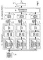
- FIG. 1 A global generic architecture of the functional components of a laser weapon system is presented.
- a power supply and conditioning acts on the pump sources, which generate an effective jet using the laser medium, which is subsequently entered into the beam control unit.
- the beam control unit consists of a beam (in) coupling with subsequent beam conditioning and elements in order to enable the beam to be aligned, for example, with a target.
- the active ray then spreads via possible optical elements in the beam path and regularly through the earth's atmosphere in the direction of the target, which can be marked by a target illuminator. On the target, an effect is caused by the beam.
- Sensors and control electronics can detect, for example, turbulence of the atmosphere as well as target movements and track or communicate the effective jet using a suitable controller.
- the overall system has a considerable mass and a considerable volume, which in the case of a system of the 100 kW power class can easily amount to several tons. It is reported in the literature that power weights of 50 kg / kW are not significantly lower than expected in the foreseeable future. Thus, it is clear that the air-supported platforms suitable for installing such a laser system as carriers of such a device are subject to certain restrictions in their minimum possible size.
- electrochemical energy storage bring a significant need for space and mass, which at a given total mass and / or given space of a possible carrier platform significant restrictions on a limited duration of use.
- a certain amount of time may be required to complete it, e.g. by charging or replacing the energy storage, ready for the next use. This severely limits the availability of such a system.
- a storage of electrical energy in principle for example by means of flywheel storage, electrochemical accumulators or high-capacitive capacitors, so-called supercaps occur.
- Such systems are expected to achieve, at best, gravimetric storage densities of 100 Wh / kg, corresponding to 360 kJ / kg, possibly 500 to 1000 Wh / kg, corresponding to 1800-3600 kJ / kg.
- working on a target by means of laser radiation from the air is preferable in comparison to working from the ground in that it reduces the hindering influence of the atmosphere in the form of turbulent disturbance or scattering on aerosols of the beam. This is partly because the cumulative influence of the The first section of the beam path for the overall result outweighs and both the turbulent influence and the aerosol concentration decreases rapidly with increasing altitude.
- FIG. 2 a plurality of exemplarily combined laser weapon systems for increasing energy. These are connected to a common power supply 24, but otherwise constitute separate units.
- the individual laser generating units are in turn connected to output stage elements 8 using optical fibers 18, in particular a single optical fiber 18. This entirety of the output stage elements 8 is arranged on the air-supported portion 12b.
- Each of the output stage elements 8 is connected to a (further) beam coupling unit 20 using an optical fiber 9 or an optical free jet 9.
- the individual beam components of the individual output stage elements 8 are now combined and forwarded via an optical fiber 9 or a further optical free jet 9 to a radiation optics element 10 for emitting the effective beam 22.
- An embodiment of FIG. 5 represents in particular a scalable system, since a desired or required output power can be realized by appropriate adaptation of the number of individual modules.
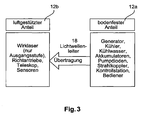
- FIG. 3 shows an exemplary division of the components of an airborne laser weapon system according to the invention in the soil-solid portion 12a and the airborne portion 12b.
- the comparatively heavy components of the laser weapon system such as generator, cooling elements with cooling fluid, accumulators, pump diodes, jet coupler and the control station of an operator are concentrated or arranged in the bottom-solid portion 12a.
- the comparatively easy or ultimately for the quality of the laser beam Necessary components such as active laser element (s), in particular its Ausganssaw (s), straightening, telescope and sensors required for this purpose may be provided on the air-supported platform 12b and connected by a comparatively long, eg several kilometers, optical waveguide 18 to the bottom portion 12a be.
- the optical waveguide 18 transmits energy, on the one hand, from the bottom platform 12a to the aerial platform 12b, as well as control and control data, on the other hand, between the bottom platform 12a and the aerial platform 12b.
- those components which are responsible for the final beam quality are preferably provided on the aerial platform 12b.
- the associated carrier will typically be a ground based platform, be it a land-based or anchored platform or a vehicle.
- the carrier is a watercraft, ship or underwater vehicle.
- the output stage described may in particular be a fiber laser, with the output stage either ending again with a fiber output of short length or finally a free jet emerging from it.
- the described output stage is another type of optically pumped laser source, in which the medium is pronounced as a rod, slab or disk laser or a number or combination of such geometries, in which case preferably Finally, a free jet is sent out. In all cases, the actual beam of high beam power and beam quality required for the effect is only generated aboard the airborne platform.
- the output stage contributes significantly to the optical output power of the laser source, that is, has a power amplification significantly greater than 1. Rather, an output stage is also conceivable which largely passively compensates only the deterioration of the beam properties caused by the upstream stages during the transmission with regard to mode quality or beam divergence or the spectral or time-dependent properties of the beam.
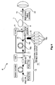
- FIG Fig. 4 Applied to a current fiber laser architecture is an exemplary embodiment in FIG Fig. 4 which may look such that the above-mentioned output stage consists of the labeled active fiber, the interfaces being made up of the locations marked B, C and D, which are distinguished in that, unlike a classical concept which the interface consists of the point marked A, which does not at the same time high performance and high demands on the transmission behavior exist.
- an optical waveguide of suitable shape and great length, eg many kilometers, may be spliced and connect the base to the aircraft in order to reach the intended destination.
- FIG. 4 shows, by way of example, two pump laser diodes and, with the active fiber or the master oscillator, generates a laser beam with the input power for the downstream fiber amplifier or an optically pumped fiber 16b.
- Seed laser unit 14 has an exemplary power of 1 kW and is coupled to the output stage element 8 using an optical fiber 18a.
- Pump laser units 16a are connected to a beam coupler unit 20 using optical fibers 18b, which in turn is connected to optical fiber 18c on the output stage member 8.
- the beam coupler unit 20 may in this case be part of the output stage element 8, or alternatively be arranged at least on the fully movable portion 12b.
- either the optical fibers 18a, b or 18a, c can pass between provide the stationary / partial mobile part 12a and the fully mobile part 12b.
- FIG. 4 shows various coupling points 11 of the pump laser units 16a and the beam coupler unit 20 in the output stage element 8, in particular before and after the fiber amplifier unit 16b.
- the effective beam in the optical fiber 18 within the output stage element 8 is now passed on using an optical fiber 9 or an optical free jet 9 to a radiation optics element 10, which may direct the targeted beam 22 or deliberately, especially in a half-space, depending on the configuration
- the effective beam 22 can thus be aligned with a target and there achieve a required or desired effect.
Landscapes
- Engineering & Computer Science (AREA)
- Physics & Mathematics (AREA)
- Optics & Photonics (AREA)
- Radar, Positioning & Navigation (AREA)
- Remote Sensing (AREA)
- General Engineering & Computer Science (AREA)
- Electromagnetism (AREA)
- Computer Networks & Wireless Communication (AREA)
- Signal Processing (AREA)
- Lasers (AREA)
- Optical Radar Systems And Details Thereof (AREA)
- Aviation & Aerospace Engineering (AREA)
Applications Claiming Priority (1)
| Application Number | Priority Date | Filing Date | Title |
|---|---|---|---|
| DE102013016646.2A DE102013016646A1 (de) | 2013-10-05 | 2013-10-05 | Luftgestütztes Laserwaffensystem |
Publications (3)
| Publication Number | Publication Date |
|---|---|
| EP2857792A1 true EP2857792A1 (fr) | 2015-04-08 |
| EP2857792B1 EP2857792B1 (fr) | 2017-12-06 |
| EP2857792B2 EP2857792B2 (fr) | 2020-09-23 |
Family
ID=51702963
Family Applications (1)
| Application Number | Title | Priority Date | Filing Date |
|---|---|---|---|
| EP14003386.1A Active EP2857792B2 (fr) | 2013-10-05 | 2014-10-01 | système d'arme laser aérien |
Country Status (6)
| Country | Link |
|---|---|
| US (1) | US9587915B2 (fr) |
| EP (1) | EP2857792B2 (fr) |
| DE (1) | DE102013016646A1 (fr) |
| ES (1) | ES2657973T5 (fr) |
| IL (1) | IL234958B (fr) |
| SG (1) | SG10201405717PA (fr) |
Families Citing this family (9)
| Publication number | Priority date | Publication date | Assignee | Title |
|---|---|---|---|---|
| WO2012135314A1 (fr) | 2011-03-29 | 2012-10-04 | Rolls-Royce North American Technologies Inc. | Système de véhicule |
| US9425580B1 (en) * | 2015-05-11 | 2016-08-23 | The United States Of America As Represented By The Secretary Of The Navy | Modular laser system |
| US10794667B2 (en) * | 2017-01-04 | 2020-10-06 | Rolls-Royce Corporation | Optical thermal profile |
| DE102017116983A1 (de) * | 2017-07-27 | 2019-01-31 | Lion Smart Gmbh | Übertragungsvorrichtung, Datenerfassungsvorrichtung, System aus Temperiervorrichtung und Datenerfassungsvorrichtung, Batteriesystem sowie Verfahren zum Übermitteln von Zustandsdaten |
| US10727769B2 (en) | 2017-09-22 | 2020-07-28 | Hamilton Sundstrand Corporation | Voltage regulation of permanent magnet generator with extended speed range |
| US11298063B2 (en) * | 2019-10-20 | 2022-04-12 | Bao Q Tran | Hydrogen powered device |
| DE102022117041A1 (de) | 2022-07-08 | 2024-01-11 | Universität Stuttgart, Körperschaft Des Öffentlichen Rechts | Laseranordnung und Verfahren zur Bearbeitung von Objekten mittels eines Laserstrahls |
| US20250130022A1 (en) * | 2023-10-24 | 2025-04-24 | Applied Research Associates, Inc. | Laser system |
| IL311723A (en) * | 2024-03-26 | 2025-10-01 | Nextvision Stabilized Systems Ltd | Portable laser-based drone neutralizer |
Citations (3)
| Publication number | Priority date | Publication date | Assignee | Title |
|---|---|---|---|---|
| US5208699A (en) * | 1991-12-20 | 1993-05-04 | Hughes Aircraft Company | Compensated, SBS-free optical beam amplification and delivery apparatus and method |
| US20040075884A1 (en) * | 2002-10-17 | 2004-04-22 | Byren Robert W. | Phase conjugate relay mirror apparatus for high energy laser system and method |
| WO2006103655A2 (fr) * | 2005-03-30 | 2006-10-05 | Rafael - Armament Development Authority Ltd. | Dispositif laser a fibre pour neutraliser des engins non eclates |
Family Cites Families (17)
| Publication number | Priority date | Publication date | Assignee | Title |
|---|---|---|---|---|
| DE3940938C2 (de) * | 1989-12-12 | 1998-12-03 | Kabelmetal Electro Gmbh | Zugfeste Steuerleitung für ferngesteuerte Geräte |
| DE19808777A1 (de) * | 1998-03-03 | 1999-09-09 | Quaas | Fesselflugkörper als mobiles Beobachtungs- und Meßsystem |
| IL130904A (en) † | 1998-08-11 | 2004-07-25 | Trw Inc | Fiber laser system with high average power with phase front control |
| US6422506B1 (en) * | 2000-10-12 | 2002-07-23 | The United States Of America As Represented By The Secretary Of The Navy | Towed airborne array system |
| US6785315B1 (en) * | 2001-09-24 | 2004-08-31 | Northrop Grumman Corporation | Mobile tactical high energy laser weapon system and method for generating a high energy laser beam |
| EP1629299B1 (fr) † | 2003-06-04 | 2010-11-10 | Elop Electro-Optics Industries Ltd. | Systeme de brouillage faisant appel a un laser a fibres |
| US7088743B2 (en) † | 2004-03-15 | 2006-08-08 | Northrop Grumman Corp. | Laser source comprising amplifier and adaptive wavefront/polarization driver |
| US7336345B2 (en) † | 2005-07-08 | 2008-02-26 | Lockheed Martin Corporation | LADAR system with SAL follower |
| DE102007049436B4 (de) † | 2007-10-16 | 2009-07-09 | Lfk-Lenkflugkörpersysteme Gmbh | Faserlaser-Anordnung hoher Strahlleistung |
| AU2009294243A1 (en) * | 2008-09-19 | 2010-03-25 | Shilat Imaging Ltd | Aerial observation system |
| US8581771B2 (en) * | 2009-07-28 | 2013-11-12 | The United States Of America As Represented By The Secretary Of The Navy | Scene illuminator |
| US8635938B2 (en) * | 2011-05-25 | 2014-01-28 | Raytheon Company | Retractable rotary turret |
| US8654314B2 (en) * | 2011-05-25 | 2014-02-18 | Raytheon Company | Rapidly deployable high power laser beam delivery system |
| US8738198B2 (en) * | 2011-05-26 | 2014-05-27 | Foster-Miller, Inc. | Robot surveillance system and method |
| WO2013013219A1 (fr) * | 2011-07-20 | 2013-01-24 | L-3 Communications Corporation | Système et procédé de charge utile amarrée |
| DE102012000672A1 (de) * | 2011-10-21 | 2013-04-25 | Lfk-Lenkflugkörpersysteme Gmbh | Verteilte Energieversorgung eines Laserwaffensystems |
| DE102012015074C5 (de) † | 2012-07-31 | 2018-03-29 | Mbda Deutschland Gmbh | Neuartige Strahleinrichtung für ein Laserwaffensystem |
-
2013
- 2013-10-05 DE DE102013016646.2A patent/DE102013016646A1/de not_active Ceased
-
2014
- 2014-09-15 SG SG10201405717PA patent/SG10201405717PA/en unknown
- 2014-10-01 EP EP14003386.1A patent/EP2857792B2/fr active Active
- 2014-10-01 ES ES14003386T patent/ES2657973T5/es active Active
- 2014-10-02 IL IL234958A patent/IL234958B/en active IP Right Grant
- 2014-10-03 US US14/505,754 patent/US9587915B2/en active Active
Patent Citations (3)
| Publication number | Priority date | Publication date | Assignee | Title |
|---|---|---|---|---|
| US5208699A (en) * | 1991-12-20 | 1993-05-04 | Hughes Aircraft Company | Compensated, SBS-free optical beam amplification and delivery apparatus and method |
| US20040075884A1 (en) * | 2002-10-17 | 2004-04-22 | Byren Robert W. | Phase conjugate relay mirror apparatus for high energy laser system and method |
| WO2006103655A2 (fr) * | 2005-03-30 | 2006-10-05 | Rafael - Armament Development Authority Ltd. | Dispositif laser a fibre pour neutraliser des engins non eclates |
Also Published As
| Publication number | Publication date |
|---|---|
| ES2657973T3 (es) | 2018-03-07 |
| SG10201405717PA (en) | 2015-05-28 |
| US20160153751A1 (en) | 2016-06-02 |
| ES2657973T5 (es) | 2021-06-08 |
| US9587915B2 (en) | 2017-03-07 |
| EP2857792B2 (fr) | 2020-09-23 |
| EP2857792B1 (fr) | 2017-12-06 |
| DE102013016646A1 (de) | 2015-04-09 |
| IL234958B (en) | 2019-09-26 |
| IL234958A0 (en) | 2014-12-31 |
Similar Documents
| Publication | Publication Date | Title |
|---|---|---|
| EP2857792B1 (fr) | Système d'arme laser aérien | |
| EP2929615B1 (fr) | Téléalimentation sans fil en énergie pour des engins volants sans pilote | |
| EP0863627B1 (fr) | Procédé et dispositif pour le transport optique de données par satellites | |
| Moll et al. | Demonstration of high-rate laser communications from a fast airborne platform | |
| DE60313013T2 (de) | Phasenkonjugierte relaisspiegel-vorrichtung für hochenergie-lasersystem und verfahren | |
| EP2693161B1 (fr) | Dispositif de rayonnement d'un système d'arme laser | |
| EP1058409B1 (fr) | Réseau et méthode de communication de données sans fil au moyen de relais volants | |
| EP1821060B1 (fr) | Missile sans occupant et procédé de positionnement d'un missile sans occupant désaccouplable d'un aéronef | |
| DE102022200355A1 (de) | Verfahren, Abwehrdrohne und Abwehrsystem zur Abwehr einer Fremddrohne | |
| EP1679808B1 (fr) | Système pour la transmission bidirectionnelle optique en espace libre de données en duplex intégral | |
| Yalçin | Fiber-optic drone technologies: A multidisciplinary review from communication fundamentals to military applications | |
| DE102012012898A1 (de) | System und Verfahren zur Positionsbestimmung einer Kommunikationsplattform | |
| CN210793681U (zh) | 一种无人机机身损坏监测系统 | |
| DE102018100891A1 (de) | Hochleistungslaser, insbesondere Laserwaffe | |
| DE102013016645B3 (de) | Energieübertragung zu einem Unterwasserfahrzeug mittels Lichtwellenleiter | |
| EP2664889B1 (fr) | Détermination de position et transmission de données à l'aide d'un laser | |
| DE102006001424A1 (de) | System zur optischen Freiraum-Datenübertragung zwischen beweglichen Kommunikationspartnern | |
| RU2859570C1 (ru) | Система радиосвязи с беспилотными летательными аппаратами | |
| Nguyen et al. | Land, sea, and air unmanned systems research and development at SPAWAR Systems Center Pacific | |
| DE3008700C2 (de) | System zur optischen Informationsübertragung zwischen einer Bodenstation und einem Luftfahrzeug | |
| RU2652914C1 (ru) | Способ наземной и воздушной доставки постановщиков радиопомех с использованием мобильного робототехнического комплекса радиоэлектронной борьбы | |
| DE102008020959A1 (de) | Verfahren und Apparatur zur Erkennung und Vermeidung von Beschusssituationen beim Betrieb von Luftfahrzeugen | |
| Thibadoux | Robotic acquisition programs: Technical and performance challenges | |
| Ghosh | Application of unmanned combat aerial vehicles in future battles of the subcontinent | |
| DE102009027683B4 (de) | Sendevorrichtung zum Senden von Information von einem Benutzer zu einem Empfänger |
Legal Events
| Date | Code | Title | Description |
|---|---|---|---|
| PUAI | Public reference made under article 153(3) epc to a published international application that has entered the european phase |
Free format text: ORIGINAL CODE: 0009012 |
|
| 17P | Request for examination filed |
Effective date: 20141001 |
|
| AK | Designated contracting states |
Kind code of ref document: A1 Designated state(s): AL AT BE BG CH CY CZ DE DK EE ES FI FR GB GR HR HU IE IS IT LI LT LU LV MC MK MT NL NO PL PT RO RS SE SI SK SM TR |
|
| AX | Request for extension of the european patent |
Extension state: BA ME |
|
| R17P | Request for examination filed (corrected) |
Effective date: 20150703 |
|
| GRAP | Despatch of communication of intention to grant a patent |
Free format text: ORIGINAL CODE: EPIDOSNIGR1 |
|
| STAA | Information on the status of an ep patent application or granted ep patent |
Free format text: STATUS: GRANT OF PATENT IS INTENDED |
|
| INTG | Intention to grant announced |
Effective date: 20170623 |
|
| GRAS | Grant fee paid |
Free format text: ORIGINAL CODE: EPIDOSNIGR3 |
|
| GRAA | (expected) grant |
Free format text: ORIGINAL CODE: 0009210 |
|
| STAA | Information on the status of an ep patent application or granted ep patent |
Free format text: STATUS: THE PATENT HAS BEEN GRANTED |
|
| AK | Designated contracting states |
Kind code of ref document: B1 Designated state(s): AL AT BE BG CH CY CZ DE DK EE ES FI FR GB GR HR HU IE IS IT LI LT LU LV MC MK MT NL NO PL PT RO RS SE SI SK SM TR |
|
| REG | Reference to a national code |
Ref country code: GB Ref legal event code: FG4D Free format text: NOT ENGLISH |
|
| REG | Reference to a national code |
Ref country code: AT Ref legal event code: REF Ref document number: 952773 Country of ref document: AT Kind code of ref document: T Effective date: 20171215 Ref country code: CH Ref legal event code: EP |
|
| REG | Reference to a national code |
Ref country code: IE Ref legal event code: FG4D Free format text: LANGUAGE OF EP DOCUMENT: GERMAN |
|
| REG | Reference to a national code |
Ref country code: DE Ref legal event code: R096 Ref document number: 502014006448 Country of ref document: DE |
|
| REG | Reference to a national code |
Ref country code: ES Ref legal event code: FG2A Ref document number: 2657973 Country of ref document: ES Kind code of ref document: T3 Effective date: 20180307 |
|
| REG | Reference to a national code |
Ref country code: NL Ref legal event code: MP Effective date: 20171206 |
|
| REG | Reference to a national code |
Ref country code: LT Ref legal event code: MG4D |
|
| PG25 | Lapsed in a contracting state [announced via postgrant information from national office to epo] |
Ref country code: LT Free format text: LAPSE BECAUSE OF FAILURE TO SUBMIT A TRANSLATION OF THE DESCRIPTION OR TO PAY THE FEE WITHIN THE PRESCRIBED TIME-LIMIT Effective date: 20171206 Ref country code: NO Free format text: LAPSE BECAUSE OF FAILURE TO SUBMIT A TRANSLATION OF THE DESCRIPTION OR TO PAY THE FEE WITHIN THE PRESCRIBED TIME-LIMIT Effective date: 20180306 Ref country code: FI Free format text: LAPSE BECAUSE OF FAILURE TO SUBMIT A TRANSLATION OF THE DESCRIPTION OR TO PAY THE FEE WITHIN THE PRESCRIBED TIME-LIMIT Effective date: 20171206 Ref country code: SE Free format text: LAPSE BECAUSE OF FAILURE TO SUBMIT A TRANSLATION OF THE DESCRIPTION OR TO PAY THE FEE WITHIN THE PRESCRIBED TIME-LIMIT Effective date: 20171206 |
|
| PG25 | Lapsed in a contracting state [announced via postgrant information from national office to epo] |
Ref country code: GR Free format text: LAPSE BECAUSE OF FAILURE TO SUBMIT A TRANSLATION OF THE DESCRIPTION OR TO PAY THE FEE WITHIN THE PRESCRIBED TIME-LIMIT Effective date: 20180307 Ref country code: RS Free format text: LAPSE BECAUSE OF FAILURE TO SUBMIT A TRANSLATION OF THE DESCRIPTION OR TO PAY THE FEE WITHIN THE PRESCRIBED TIME-LIMIT Effective date: 20171206 Ref country code: HR Free format text: LAPSE BECAUSE OF FAILURE TO SUBMIT A TRANSLATION OF THE DESCRIPTION OR TO PAY THE FEE WITHIN THE PRESCRIBED TIME-LIMIT Effective date: 20171206 Ref country code: LV Free format text: LAPSE BECAUSE OF FAILURE TO SUBMIT A TRANSLATION OF THE DESCRIPTION OR TO PAY THE FEE WITHIN THE PRESCRIBED TIME-LIMIT Effective date: 20171206 Ref country code: BG Free format text: LAPSE BECAUSE OF FAILURE TO SUBMIT A TRANSLATION OF THE DESCRIPTION OR TO PAY THE FEE WITHIN THE PRESCRIBED TIME-LIMIT Effective date: 20180306 |
|
| PG25 | Lapsed in a contracting state [announced via postgrant information from national office to epo] |
Ref country code: NL Free format text: LAPSE BECAUSE OF FAILURE TO SUBMIT A TRANSLATION OF THE DESCRIPTION OR TO PAY THE FEE WITHIN THE PRESCRIBED TIME-LIMIT Effective date: 20171206 |
|
| PG25 | Lapsed in a contracting state [announced via postgrant information from national office to epo] |
Ref country code: CZ Free format text: LAPSE BECAUSE OF FAILURE TO SUBMIT A TRANSLATION OF THE DESCRIPTION OR TO PAY THE FEE WITHIN THE PRESCRIBED TIME-LIMIT Effective date: 20171206 Ref country code: EE Free format text: LAPSE BECAUSE OF FAILURE TO SUBMIT A TRANSLATION OF THE DESCRIPTION OR TO PAY THE FEE WITHIN THE PRESCRIBED TIME-LIMIT Effective date: 20171206 Ref country code: SK Free format text: LAPSE BECAUSE OF FAILURE TO SUBMIT A TRANSLATION OF THE DESCRIPTION OR TO PAY THE FEE WITHIN THE PRESCRIBED TIME-LIMIT Effective date: 20171206 |
|
| PG25 | Lapsed in a contracting state [announced via postgrant information from national office to epo] |
Ref country code: RO Free format text: LAPSE BECAUSE OF FAILURE TO SUBMIT A TRANSLATION OF THE DESCRIPTION OR TO PAY THE FEE WITHIN THE PRESCRIBED TIME-LIMIT Effective date: 20171206 Ref country code: SM Free format text: LAPSE BECAUSE OF FAILURE TO SUBMIT A TRANSLATION OF THE DESCRIPTION OR TO PAY THE FEE WITHIN THE PRESCRIBED TIME-LIMIT Effective date: 20171206 Ref country code: PL Free format text: LAPSE BECAUSE OF FAILURE TO SUBMIT A TRANSLATION OF THE DESCRIPTION OR TO PAY THE FEE WITHIN THE PRESCRIBED TIME-LIMIT Effective date: 20171206 |
|
| REG | Reference to a national code |
Ref country code: DE Ref legal event code: R026 Ref document number: 502014006448 Country of ref document: DE |
|
| PLBI | Opposition filed |
Free format text: ORIGINAL CODE: 0009260 |
|
| PLAX | Notice of opposition and request to file observation + time limit sent |
Free format text: ORIGINAL CODE: EPIDOSNOBS2 |
|
| PG25 | Lapsed in a contracting state [announced via postgrant information from national office to epo] |
Ref country code: MT Free format text: LAPSE BECAUSE OF FAILURE TO SUBMIT A TRANSLATION OF THE DESCRIPTION OR TO PAY THE FEE WITHIN THE PRESCRIBED TIME-LIMIT Effective date: 20171206 |
|
| 26 | Opposition filed |
Opponent name: RHEINMETALL WAFFE MUNITION GMBH Effective date: 20180906 |
|
| REG | Reference to a national code |
Ref country code: FR Ref legal event code: PLFP Year of fee payment: 5 |
|
| PG25 | Lapsed in a contracting state [announced via postgrant information from national office to epo] |
Ref country code: DK Free format text: LAPSE BECAUSE OF FAILURE TO SUBMIT A TRANSLATION OF THE DESCRIPTION OR TO PAY THE FEE WITHIN THE PRESCRIBED TIME-LIMIT Effective date: 20171206 Ref country code: SI Free format text: LAPSE BECAUSE OF FAILURE TO SUBMIT A TRANSLATION OF THE DESCRIPTION OR TO PAY THE FEE WITHIN THE PRESCRIBED TIME-LIMIT Effective date: 20171206 |
|
| PLBB | Reply of patent proprietor to notice(s) of opposition received |
Free format text: ORIGINAL CODE: EPIDOSNOBS3 |
|
| REG | Reference to a national code |
Ref country code: CH Ref legal event code: PL |
|
| REG | Reference to a national code |
Ref country code: BE Ref legal event code: MM Effective date: 20181031 |
|
| PG25 | Lapsed in a contracting state [announced via postgrant information from national office to epo] |
Ref country code: MC Free format text: LAPSE BECAUSE OF FAILURE TO SUBMIT A TRANSLATION OF THE DESCRIPTION OR TO PAY THE FEE WITHIN THE PRESCRIBED TIME-LIMIT Effective date: 20171206 Ref country code: LU Free format text: LAPSE BECAUSE OF NON-PAYMENT OF DUE FEES Effective date: 20181001 |
|
| REG | Reference to a national code |
Ref country code: IE Ref legal event code: MM4A |
|
| PG25 | Lapsed in a contracting state [announced via postgrant information from national office to epo] |
Ref country code: LI Free format text: LAPSE BECAUSE OF NON-PAYMENT OF DUE FEES Effective date: 20181031 Ref country code: CH Free format text: LAPSE BECAUSE OF NON-PAYMENT OF DUE FEES Effective date: 20181031 Ref country code: BE Free format text: LAPSE BECAUSE OF NON-PAYMENT OF DUE FEES Effective date: 20181031 |
|
| PG25 | Lapsed in a contracting state [announced via postgrant information from national office to epo] |
Ref country code: IE Free format text: LAPSE BECAUSE OF NON-PAYMENT OF DUE FEES Effective date: 20181001 |
|
| PG25 | Lapsed in a contracting state [announced via postgrant information from national office to epo] |
Ref country code: TR Free format text: LAPSE BECAUSE OF FAILURE TO SUBMIT A TRANSLATION OF THE DESCRIPTION OR TO PAY THE FEE WITHIN THE PRESCRIBED TIME-LIMIT Effective date: 20171206 |
|
| PG25 | Lapsed in a contracting state [announced via postgrant information from national office to epo] |
Ref country code: PT Free format text: LAPSE BECAUSE OF FAILURE TO SUBMIT A TRANSLATION OF THE DESCRIPTION OR TO PAY THE FEE WITHIN THE PRESCRIBED TIME-LIMIT Effective date: 20171206 Ref country code: HU Free format text: LAPSE BECAUSE OF FAILURE TO SUBMIT A TRANSLATION OF THE DESCRIPTION OR TO PAY THE FEE WITHIN THE PRESCRIBED TIME-LIMIT; INVALID AB INITIO Effective date: 20141001 |
|
| PG25 | Lapsed in a contracting state [announced via postgrant information from national office to epo] |
Ref country code: MK Free format text: LAPSE BECAUSE OF NON-PAYMENT OF DUE FEES Effective date: 20171206 Ref country code: CY Free format text: LAPSE BECAUSE OF FAILURE TO SUBMIT A TRANSLATION OF THE DESCRIPTION OR TO PAY THE FEE WITHIN THE PRESCRIBED TIME-LIMIT Effective date: 20171206 |
|
| PG25 | Lapsed in a contracting state [announced via postgrant information from national office to epo] |
Ref country code: AL Free format text: LAPSE BECAUSE OF FAILURE TO SUBMIT A TRANSLATION OF THE DESCRIPTION OR TO PAY THE FEE WITHIN THE PRESCRIBED TIME-LIMIT Effective date: 20171206 Ref country code: IS Free format text: LAPSE BECAUSE OF FAILURE TO SUBMIT A TRANSLATION OF THE DESCRIPTION OR TO PAY THE FEE WITHIN THE PRESCRIBED TIME-LIMIT Effective date: 20180406 |
|
| PUAH | Patent maintained in amended form |
Free format text: ORIGINAL CODE: 0009272 |
|
| STAA | Information on the status of an ep patent application or granted ep patent |
Free format text: STATUS: PATENT MAINTAINED AS AMENDED |
|
| 27A | Patent maintained in amended form |
Effective date: 20200923 |
|
| AK | Designated contracting states |
Kind code of ref document: B2 Designated state(s): AL AT BE BG CH CY CZ DE DK EE ES FI FR GB GR HR HU IE IS IT LI LT LU LV MC MK MT NL NO PL PT RO RS SE SI SK SM TR |
|
| REG | Reference to a national code |
Ref country code: DE Ref legal event code: R102 Ref document number: 502014006448 Country of ref document: DE |
|
| REG | Reference to a national code |
Ref country code: AT Ref legal event code: MM01 Ref document number: 952773 Country of ref document: AT Kind code of ref document: T Effective date: 20191001 |
|
| PG25 | Lapsed in a contracting state [announced via postgrant information from national office to epo] |
Ref country code: AT Free format text: LAPSE BECAUSE OF NON-PAYMENT OF DUE FEES Effective date: 20191001 |
|
| REG | Reference to a national code |
Ref country code: ES Ref legal event code: DC2A Ref document number: 2657973 Country of ref document: ES Kind code of ref document: T5 Effective date: 20210608 |
|
| P01 | Opt-out of the competence of the unified patent court (upc) registered |
Effective date: 20230509 |
|
| PGFP | Annual fee paid to national office [announced via postgrant information from national office to epo] |
Ref country code: DE Payment date: 20251031 Year of fee payment: 12 |
|
| PGFP | Annual fee paid to national office [announced via postgrant information from national office to epo] |
Ref country code: GB Payment date: 20251022 Year of fee payment: 12 |
|
| PGFP | Annual fee paid to national office [announced via postgrant information from national office to epo] |
Ref country code: IT Payment date: 20251024 Year of fee payment: 12 |
|
| PGFP | Annual fee paid to national office [announced via postgrant information from national office to epo] |
Ref country code: FR Payment date: 20251030 Year of fee payment: 12 |
|
| PGFP | Annual fee paid to national office [announced via postgrant information from national office to epo] |
Ref country code: ES Payment date: 20251210 Year of fee payment: 12 |