EP2858413A1 - Procédé et système de commutation de noeuds de services - Google Patents
Procédé et système de commutation de noeuds de services Download PDFInfo
- Publication number
- EP2858413A1 EP2858413A1 EP13796354.2A EP13796354A EP2858413A1 EP 2858413 A1 EP2858413 A1 EP 2858413A1 EP 13796354 A EP13796354 A EP 13796354A EP 2858413 A1 EP2858413 A1 EP 2858413A1
- Authority
- EP
- European Patent Office
- Prior art keywords
- serving
- service point
- point
- user data
- target
- Prior art date
- Legal status (The legal status is an assumption and is not a legal conclusion. Google has not performed a legal analysis and makes no representation as to the accuracy of the status listed.)
- Withdrawn
Links
Images

Classifications
-
- H—ELECTRICITY
- H04—ELECTRIC COMMUNICATION TECHNIQUE
- H04W—WIRELESS COMMUNICATION NETWORKS
- H04W36/00—Hand-off or reselection arrangements
- H04W36/12—Reselecting a serving backbone network switching or routing node
-
- H—ELECTRICITY
- H04—ELECTRIC COMMUNICATION TECHNIQUE
- H04L—TRANSMISSION OF DIGITAL INFORMATION, e.g. TELEGRAPHIC COMMUNICATION
- H04L67/00—Network arrangements or protocols for supporting network services or applications
- H04L67/01—Protocols
- H04L67/10—Protocols in which an application is distributed across nodes in the network
- H04L67/1001—Protocols in which an application is distributed across nodes in the network for accessing one among a plurality of replicated servers
- H04L67/1036—Load balancing of requests to servers for services different from user content provisioning, e.g. load balancing across domain name servers
-
- H—ELECTRICITY
- H04—ELECTRIC COMMUNICATION TECHNIQUE
- H04L—TRANSMISSION OF DIGITAL INFORMATION, e.g. TELEGRAPHIC COMMUNICATION
- H04L67/00—Network arrangements or protocols for supporting network services or applications
- H04L67/50—Network services
- H04L67/56—Provisioning of proxy services
- H04L67/563—Data redirection of data network streams
-
- H—ELECTRICITY
- H04—ELECTRIC COMMUNICATION TECHNIQUE
- H04W—WIRELESS COMMUNICATION NETWORKS
- H04W36/00—Hand-off or reselection arrangements
- H04W36/0005—Control or signalling for completing the hand-off
- H04W36/0011—Control or signalling for completing the hand-off for data sessions of end-to-end connection
- H04W36/0019—Control or signalling for completing the hand-off for data sessions of end-to-end connection adapted for mobile IP [MIP]
-
- H—ELECTRICITY
- H04—ELECTRIC COMMUNICATION TECHNIQUE
- H04W—WIRELESS COMMUNICATION NETWORKS
- H04W36/00—Hand-off or reselection arrangements
- H04W36/0005—Control or signalling for completing the hand-off
- H04W36/0055—Transmission or use of information for re-establishing the radio link
- H04W36/0064—Transmission or use of information for re-establishing the radio link of control information between different access points
-
- H—ELECTRICITY
- H04—ELECTRIC COMMUNICATION TECHNIQUE
- H04W—WIRELESS COMMUNICATION NETWORKS
- H04W36/00—Hand-off or reselection arrangements
- H04W36/0005—Control or signalling for completing the hand-off
- H04W36/0055—Transmission or use of information for re-establishing the radio link
- H04W36/0066—Transmission or use of information for re-establishing the radio link of control information between different types of networks in order to establish a new radio link in the target network
Definitions
- the present disclosure relates to Internet technology, and particularly, to a method and system of changing service points.
- multiple service points are generally adopted for load-balancing because a single server has limited computing capabilities and cannot handle a large amount of data requests at the same time.
- multiple service points may be deployed according to geographical areas, e.g., a service point is deployed in each province, and each service point processes data requests initiated by users from the area where the service point locates.
- users are served by respective dedicated service points, and user data of users is also stored in respective service points, and users served by different service points usually can not directly communicate with each other.
- game players in different service zones are not able to play the game together in the same game process (players served by the same server can play the game together in the same game process).
- a user may need to change its serving service point.
- user 1 served by service point A has the need of exchanging data with user 2 served by service point B
- user 1 is required to fill out an application form to apply for changing a service point.
- an administrator modifies a configuration file to change the serving service point of user 1 from service point A into service point B, and transfers user data of user 1 from service pint A to service point B.
- user 1 After user 1 finishes data exchange with user 2 via service point B, user 1 has to fill out another application form, and the administrator performs the same operations again to change the serving service point of user 1 back to be service point A and transfer user data of user 1 to service point A.
- Various examples of the present disclosure provide a method of changing service points, which changes service points in real time.
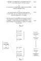
- a serving service point obtains a changing request, and obtains a user identity from the changing request; the serving service point determines a target service point by using the changing request; the serving service point obtains serving user data corresponding to the user identity, sends the serving user data to the target service point; and the serving service point receives a changing response from the target service point, redirects a client corresponding to the user identity to connect to the target service point.
- the serving service point may determine the target service point by using the changing request through the following procedures:
- the routing information may include proxy identities of proxy points and a hopping sequence of the proxy points; the serving service point may send the serving user data to the target service point through the following procedures:
- the proxy points may belong to at least one hierarchy; the proxy points may forward the serving user data to the target service point hop by hop according to the hopping sequence of the proxy points in the routing information through the following procedures:
- the serving service point before sending the serving user data to the target service point, the serving service point may:
- the serving service point before sending the serving user data to the target service point, the serving service point may:
- the target service point may locate the serving service point
- the target service point may receive the point returning response, and delete the target user data.
- the target service point may:
- the serving service point may:
- Various examples of the present disclosure provide a system of changing service points, which changes service points in real time.
- the system of changing service points may include service points.
- the service points include a serving service point.
- the serving service point may include:
- the system may also include a routing point, adapted to store routing information on routes between service points; the serving point locating module is also adapted to obtain an identity of the target service point from the changing request, obtain routing information on a route to the target service point from the pre-defined routing point by using the identity of the target service point.
- the system may also include a plurality of proxy points;
- the routing information may include proxy identities of proxy points and a hopping sequence of the proxy points;
- the serving user data sending module is also adapted to obtain the proxy points for forwarding the serving user data by using the proxy identities in the routing information, and send the serving user data to the proxy points according to the routing information;
- the proxy points are adapted to forward the serving user data to the target service point hop by hop according to the hopping sequence in the routing information.
- the proxy points may belong to at least one hierarchy
- the serving service point may also include a workload obtaining module, adapted to obtain first information on workload of the proxy points identified in the routing information and second information on workload of the target service point; the serving service point may also include a queue processing module, adapted to process the changing request by using a blocking queue according to the first information and the second information.
- a workload obtaining module adapted to obtain first information on workload of the proxy points identified in the routing information and second information on workload of the target service point
- the serving service point may also include a queue processing module, adapted to process the changing request by using a blocking queue according to the first information and the second information.
- the serving service point may also include a serving user data filtering module, adapted to filter the serving user data according to service requirements.
- the service points may also include a target service point.
- the target service point may include a target point locating module, a target user data obtaining module and a target user data sending module.
- the target point locating module is adapted to locate the serving service point.
- the target user data obtaining module is adapted to obtain target user data corresponding to the user identity stored in the target service point.
- the target user data sending module is adapted to send the target user data to the serving service point.
- the serving service point may also include a serving user data merging module, adapted to merge the target user data with the serving user data.
- the serving user data sending module is also adapted to return a point returning response to the target service point.
- connection control module is also adapted to recover a connection with the client.
- the target user data sending module is also adapted to receive a point returning response from the serving service point.
- the target service point may also include a target user data deleting module, adapted to delete the target user data.
- the target user data sending module is also adapted to return a changing response to the serving service point.
- the target service point may also include a timeout detecting module, adapted to monitor a service duration, and call the serving point locating module in response to a determination that the service duration reaches a timeout period.
- a timeout detecting module adapted to monitor a service duration, and call the serving point locating module in response to a determination that the service duration reaches a timeout period.
- the serving service point may also include a data protecting module, adapted to lock the serving user data after the serving data sending module receives changing response; and unlock the serving user data before the serving user data merging module merges the target user data with the serving user data.
- a data protecting module adapted to lock the serving user data after the serving data sending module receives changing response; and unlock the serving user data before the serving user data merging module merges the target user data with the serving user data.
- the serving service point may locate the target service point by using the changing request in real time, and send user data to the target service point.
- the serving service point redirects a connection with the client to the target service point automatically after receiving a changing response (changing acknowledgement) sent by the target service point.
- the changing request of the user can be handled in real time, and changing of service points can be implemented in real time.
- a method of changing service points may include the following procedures.
- a serving service point obtains a changing request, and obtains a user identity from the changing request.
- the serving service point refers to a service point to which a client is connected before the change of service points.
- the user may send the changing request to the serving service point via the client to apply for changing a service point.
- the changing request may include a user identity corresponding to the client that sent the changing request.
- the user may input an instruction into the client to send the changing request to the service point the client is connected to (i.e., the serving service point).
- the serving service point i.e., the serving service point
- a user may talk to a pre-determined NPC (non player controlled character) to send a changing request to the service point the user is connected to (i.e., the serving service point).
- NPC non player controlled character
- the changing request may be sent by a controlling point.
- the controlling point may be a pre-defined device for controlling operations of service points, and may force a client corresponding to a user identity to change service points according to service requirements.
- the serving service point locates a target service point by using the changing request.
- the target service point refers to a service point to which the client is to be connected after the change of service points.
- the changing request may also include an identity of the target service point.
- the procedure of the serving service point locating the target service point by using the changing request may include:
- the routing point is pre-defined point, connected to service points, and is adapted to store routing information on connections between points.
- the serving service point may locate the target service point by using the routing information.
- service points may send a heartbeat message at intervals to keep connected to the routing point.
- the procedure of the serving service point obtaining the routing information for routing to the target service point from the routing point by using the target service point identity may include:
- the serving service point may cache the routing information and the routing information into a local machine after obtaining the routing information on a route to the target service point from the pre-defined routing point by using the target service point identity.
- the procedure of the serving service point locating the target service point by using the changing request may include: the serving service point sends a route obtaining request to the routing point; the routing point allocates the target service point for the serving service point after receiving the route obtaining request, obtains routing information corresponding to the target service point allocated, and sends the routing information to the serving service point.
- the routing point may store workload information of service points connected to the routing point.
- the routing point may allocate a service point having a minimal workload (i.e., the most disengaged service point) as the target service point for the serving service point according to the workload information.
- the routing point may randomly allocate a target service point for the serving service point.
- the routing point may be deployed in a main/backup mode.
- a main routing point and a backup routing point store the same routing information.
- the main routing point may synchronize data with the backup routing point periodically.
- the serving service point may obtain the routing information on a route to the target service point from the backup routing point if the serving service point fails to obtain the routing information from the main routing information.
- the routing point may be established in a main/backup mode so that when there is a single routing point failure, the serving service point can still obtain the routing information. Therefore, data loss is prevented, and data security is improved.
- the serving service point obtains serving user data corresponding to the user identity, sends the serving user data to the target service point.
- the service point may process a data request sent by the client, generate and store user data according to a processing result.
- the serving user data refers to user data stored in the serving service point.
- the user data may be stored in a disk or a database in the serving point and associated with the user identity.
- the serving service point may filter the serving user data according to service requirements before sending the serving user data to the target service point.
- the service requirements may specify serving user data needed in data exchange between the client and the target service point.
- the serving service point filters the serving user data based on the service requirements and sends the part of serving user data obtained from the filtering that is needed in data exchange between the client and the target service point to the target service point. As such, the amount of data transmitted can be greatly reduced, data redundancy is reduced, and bandwidth utility ratio can be increased.
- the routing information may include proxy identities of proxy points and a hopping sequence of the proxy points.
- the procedure of the serving service point sending the serving user data to the target service point may include:
- the proxy points forward the serving user data to the target service point hop by hop according to the hopping sequence of the proxy points specified in the routing information.
- the proxy points may belong to at least one hierarchy.
- the procedure of the proxy points forward the serving user data to the target service point hop by hop according to the hopping sequence of the proxy points specified in the routing information may include:
- the service points are divided into a plurality of groups, and service points in each group are connected with a proxy point.
- the proxy points may belong to at least one hierarchy, i.e., proxy points of level 1, proxy points of level 2, ... and proxy points of level N.
- Proxy points of the same level may also be divided into a plurality of groups, and proxy points in one group may be connected with a proxy point from an upper level to form a multi-layer pyramid-like structure.
- Each proxy points of the bottom level are connected with each group of service points.
- the serving service point may send the serving user data in a data packet.
- the serving service point may generate the header of the data packet for the serving user data by using the routing information.
- the header of the data packet may include version information, total hops, current hops, the identity of the serving service point, the identities of the proxy points and the hopping sequence of the proxy points.
- a point ID may be the identity of a proxy point or the identity of a service point.
- the hopping sequence of the proxy points may be in the form of point identities arranged in a certain order.
- Table 1 is merely an example of routing information in a packet header, the payload of the data packet may not necessarily include a table identical or similar to Table 1.
- the procedure of the proxy points forward the serving user data to the target service point hop by hop according to the hopping sequence of the proxy points in the routing information may include:
- proxy points may be divided into multiple hierarchies to prevent the proxy points from forming a mesh network.
- the service point When a service point is added, the service point only has to establish a connection with one of the proxy points instead of establishing a connection with each of the proxy points. Thus, network capacity can be easily increased.
- Pre-setting proxy points can facilitate data transmission in a network which includes multiple sub networks and needs NAT.
- a plurality of sub networks may be pre-set based on geographical areas.
- Each sub network may include service points providing service for the geographical area.
- a gateway of a sub network may serve as a proxy point.
- the data may be forwarded by the proxy point hierarchy by hierarchy to avoid NAT which is necessary when service points are directly connected with each other.
- a proxy point may be configured in a main/backup mode.
- data may be forwarded by a backup proxy point.
- the point identity may be the IP address of the point.
- a serving service point may send a data packet to a target service point or a proxy point based on the IP address.
- a proxy point may search in a routing point for an IP address corresponding to a point identity, and send a data packet to the point by using the IP address.
- the serving service point may obtain workload information of proxy points corresponding to the routing information and workload information of the target service point before sending the serving user data to the target service point.
- the serving service point may process the changing request by using a blocking queue based on the workload information.
- Proxy points that are going to forward the serving user data may be determined by using the routing information.
- the workload information of a proxy point may include a bandwidth utility ratio, computation capability and the size of the cache of the proxy point.
- the workload information of the target service point may include a bandwidth utility ratio, computation capability and the size of the cache of the target service point.
- the workload information of the proxy point and the target service point may be stored in the routing point and may be updated at intervals.
- the serving service point may obtain the workload information from the routing point.
- the process of the serving service point processing the changing request by using a blocking queue based on the workload information may include: calculating a workload capacity by using the workload information and a pre-defined weight, performing the step of sending the serving user data to the target serve point if the load capacity is larger than a threshold, or adding the changing request into a pre-defined blocking queue if the load capacity is not larger than the threshold.
- the step of the serving service point processing the changing request by using a blocking queue based on the workload information may also include: the serving service point obtains a changing request from the blocking queue at intervals and performs the step of locating the target service point by using the changing request.
- the serving service point may send a sequence number of the position of the changing request in the blocking queue to the client.
- the client may display the sequence number.
- the sequence number may be used by the user to estimate the waiting time before the changing request is processed, which facilitates the user to control the process.
- the serving user data may include a user identity.
- the process may also include: after receiving the serving user data, the target service point validate the received serving user data, and store the serving user data and corresponding user identity, and return a changing response to the serving service point.
- the serving service point receives a changing response from the target service point, redirects the client corresponding to the user identity to connect to the target service point.
- the serving service point may obtain and send the IP address and the port of the target service point to the client corresponding to the user identity, i.e., the client corresponding to the changing request.
- the client may be the client that send the changing request or a client specified by the user identity in the changing request.
- the client may establish a connection with the target service point by using the IP address and the port.
- the changing response may also include a cipher key.
- the target service point Before sending the changing response to the serving service point, the target service point may generate a cipher key based on the serving service point and the user identity.
- the procedure of the serving service point redirecting the client to connect to the target service point may include: the serving service point may redirect a connection corresponding to the changing request to the target service point by using the cipher key.
- the cipher key is determined to be valid during the redirecting procedure, the change of service point is successful, and a connection is established between the client and the target service point. If the cipher key is determined to be invalid, the change of service point is failed.
- the target service point may delete the serving user data.
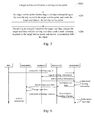
- Fig. 4 is a sequence diagram illustrating a process of changing a service point from a1 to a2 after a user sent a changing request to service point a1 via a client.
- serving user data may be forwarded through proxy point A1, proxy point A, proxy point B, proxy point B3 in turn to service point b1 during the process of changing service point from a1 to b1.
- the method of changing service points may also include the following procedures.
- the target service point locates the serving service point.
- the method of the target service point locating the serving service point may be similar to the method of the serving service point locating the target service point, thus is not described further herein.
- the target service point may obtain target user data corresponding to the user identity stored in the target service point, and send the target user data to the serving service point.
- the target user data refers to user data stored in the target service point, i.e., new data generated when the target service point processes data requests sent by the client after the change of service point.
- the method of the target service point sending the target user data to the serving service point may be similar to the method of the serving service point sending the serving user data to the target service point, thus is not described further herein.
- the serving service point receives the target user data, merges the target user data with the serving user data, returns a point returning response to the target service point, and recover a connection with the client.
- the procedure of the serving service point merging the target user data with the serving user data may include: the serving service point updates the serving user data by using the target user data.
- the serving service point may stop the redirection and send a connection recovery request to recover the connection with the client.
- the target service point may redirect the connection with the client to the serving service point, and the serving service point may passively recover the connection with the client.
- the target service point may also obtain a point returning request, and then perform the step of locating the serving service point.
- the point returning request may be initiated by the client.
- the user may initiate a point returning request via the client.
- a point returning request by talking to an NPC to request returning to the serving service point.
- the target service point may perform the step of locating the serving service point to make the client corresponding to the user identity return to the serving service point.
- the changing request may be sent by a controlling point.
- the serving service point may force the client corresponding to the user identity to return to the serving service point according to service requirements.
- the target service point may:
- the service duration refers to the length of time the target service data has been processing data requests from the clients after the client is connected to the target service point.
- the target service point may start counting the time after sending the changing response, and perform the step of locating the serving service point to return the client to the serving service point when detecting the service duration reaches a timeout period (e.g., larger than or equal to a pre-defined length of time).
- the target service point may receive the point returning response and delete the target user data.
- the client changes its service point from the serving service point to the target service point, and returns from the target service point to the serving service point after a temporary data interaction, and the target user data generated during the temporary data interaction is temporary user data.
- the target user data is only stored after merged by the serving service data with the serving user data, and does not need to be backed up. Therefore, deleting the target user data can save storage space in service points, and reduce data redundancy.
- service point a1 is the serving service point
- service point a2 is the target service point.
- Service points a1 and a2 are both connected to proxy point A1.
- the user has changed the service point from a1 to a2.
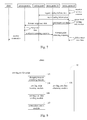
- Fig. 6 is a sequence diagram illustrating a process of changing a service point from a2 to a1 after a user sent a point returning request to service point a2 via a client.
- Fig. 7 is a sequence diagram illustrating a process of changing a service point from a2 to a1 after the service point a2 detects a service duration reaches a timeout period.
- the serving service point may lock the serving service point.
- the serving service point Before merging the target user data with the serving user data, the serving service point may unlock the serving user data.
- a flag may be added to indicate the lock and unlock of the serving user data.
- the flag indicates "locked”
- operations of writing the serving user data initiated by a process or a thread may be rejected; when the flag indicates "unlocked”, the process or the thread may be woken up to perform the writing operations on the serving user data.
- a system of changing service points may include service points.
- the service points may include a serving service point 10.
- the serving service point 10 may include: a changing request obtaining module 102, a serving point locating module 104, a serving user data obtaining module 106, a serving user data sending module 108 and a connection control module 110.
- the changing request obtaining module 102 obtains a changing request, and obtains a user identity from the changing request.
- the serving service point refers to the service point the client is connected to before the change of service points.
- the user may send the changing request to the serving service point via the client to apply for changing a service point.
- the changing request may include a user identity corresponding to the client that sent the changing request.
- the user may input an instruction into the client to send the changing request to the service point the client is connected to (i.e., the serving service point).
- the service point the client i.e., the serving service point.
- a user may talk to a specific NPC to initiate the changing request.
- the changing request may be sent by a controlling point.
- the controlling point may be a pre-defined device for controlling operations of service points, and may force a client corresponding to a user identity to change service points according to service requirements.
- the serving point locating module 104 is adapted to locate a target serving point by using the changing request.
- the target service point refers to a service point to which the client is to be connected after the change of service point.
- the changing request may also include an identity of the target service point.
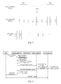
- the system may also include a routing point 20 adapted to store routing information on connections between the service points.
- the serving point locating module 104 may obtain the identity of the target service point from the changing request, and obtain routing information on a route to the target service point from a pre-defined routing point by using the identity of the target service point.
- the routing point is a pre-defined point, connected to service points, and is adapted to store routing information on connections between points.
- the serving point locating module 104 is adapted to locate a target serving point by using the changing request.
- the serving service point 10 may also include a connection maintaining module (not illustrated in the drawings) adapted to send a heartbeat message at intervals to keep connected to the routing point.
- a connection maintaining module (not illustrated in the drawings) adapted to send a heartbeat message at intervals to keep connected to the routing point.
- the serving point locating module 104 may search in a local machine for routing information corresponding to the identity of the target service point, and obtain the routing information from the pre-defined routing point by using the identity of the target service point if the routing information is not found in the local machine.
- the serving point locating module 104 may cache the identity of the target service point and corresponding routing information in the local machine after obtaining the routing information from the routing point by using the identity of the target service point.
- the serving point locating module 104 may send a route obtaining request to the routing point.
- the routing point 20 may allocate a target service point for the serving service point 10 after receiving the route obtaining request, obtain routing information corresponding to the target service point, and return the routing information to the serving service point 10.
- the routing point 20 may store workload information of service points connected to the routing point.
- the routing point 20 may allocate a service point having a minimal workload (i.e., the most disengaged service point) as the target service point for the serving service point 10 according to the workload information.
- the routing point may randomly allocate a target service point for the serving service point.
- the routing point 20 may be deployed in a main/backup mode. As shown in Fig. 2 , a main routing point and a backup routing point may store identical routing information. The main routing point may synchronize data with the backup routing point periodically. The serving service point 10 may obtain the routing information on a route to the target service point from the backup routing point if the serving service point fails to obtain the routing information from the main routing information.
- the routing point may be established in a main/backup mode so that when there is a single routing point failure, the serving service point can still obtain the routing information. Therefore, data loss is prevented, and data security is improved.
- the serving user data obtaining module 106 may obtain serving user data corresponding to the user identity.
- the service point may process a data request sent by the client, generate and store user data according to a processing result.
- the serving user data refers to user data stored in the serving service point 10.
- the user data may be stored in a disk or a database in the serving point and associated with the user identity.
- the serving service point 10 may also include a serving user data filtering module 112 adapted to filter the serving user data according to service requirements.
- the service requirements may specify the part of serving user data that is required in the data interaction between the client and the target service data.
- the serving user data filtering module 112 may filter the serving user data according to the service requirements to reduce the amount of irrelevant data transmitted. As such, data redundancy is reduced, and bandwidth utility ratio is increased.
- the serving user data sending module 108 may send the serving user data to the target service point, and receive a changing response returned by the target service point.
- the system may also include at least one proxy point 30.
- the routing information may include identities of proxy points 30 and a hopping sequence of the proxy points 30.
- the serving user data sending module 108 may obtain proxy points for forwarding data by using proxy identities in the routing information, and send the serving user data to the proxy points according to the routing information.
- the proxy points 30 may forward the serving user data to the target service point hop by hop according to the hopping sequence of the proxy points specified in the routing information.
- the proxy points 30 may belong to at least one hierarchy.
- the proxy points 30 may forward the serving user data to the target service point hop by hop and hierarchy by hierarchy according to the hopping sequence of the proxy points specified in the routing information.
- the service points may be divided into a plurality of groups, and service points in each group are connected with a proxy point.
- the proxy points may belong to at least one hierarchy, i.e., proxy points of level 1, proxy points of level 2, ... and proxy points of level N.
- Proxy points of the same level may also be divided into a plurality of groups, and proxy points in one group may be connected with a proxy point from an upper level to form a multi-layer pyramid-like structure.
- Each proxy points of the bottom level are connected with each group of service points.
- the serving user data sending module 108 may send the serving user data in a data packet.
- the serving service point may generate the header of the data packet for the serving user data by using the routing information.
- the header of the data packet may include version information, total hops, current hops, the identity of the serving service point, the identities of the proxy points and the hopping sequence of the proxy points.
- a point ID may be the identity of a proxy point or the identity of a service point.
- the hopping sequence of the proxy points may be in the form of point identities arranged in a certain order.
- Table 1 is merely an example of routing information in a packet header, the payload of the data packet may not necessarily include a table identical or similar to Table 1.
- a proxy point receives a data packet including the serving user data sent by the serving service point, parses the header of the data packet, obtains an identity of a point of the next hop (which may be the identity of a proxy point or the identity of the target service point) based on the current hops, sends the packet to the point of the next hop (which may be a proxy point or the target service point). The proxy points repeat the process until the packet is sent to the target service point.
- proxy points may be divided into multiple hierarchies to prevent the proxy points from forming a mesh network.
- the service point When a service point is added, the service point only has to establish a connection with one of the proxy points instead of establishing a connection with each of the proxy points. Thus, network capacity can be easily increased.
- Pre-setting proxy points facilitates data transmission in a network which includes multiple sub networks and needs NAT.
- a plurality of sub networks may be pre-set based on geographical areas.
- Each sub network may include service points providing service for the geographical area.
- a gateway of a sub network may serve as a proxy point.
- the data may be forwarded by the proxy point hierarchy by hierarchy to avoid NAT which is necessary when service points are directly connected with each other.
- a proxy point 30 may be configured in a main/backup mode. When a failure occurs in a main proxy point, data may be forwarded by a backup proxy point.
- the point identity may be an IP address of a point, and send the data packet by using the IP address.
- a proxy point 30 may search in the routing point 20 for an IP address corresponding to a point identity, and send a data packet to the point by using the IP address.
- the serving service point 10 may also include a workload obtaining module 114 adapted to obtain first information on workload of the proxy points identified in the routing information and second information on workload of the target service point.
- the serving service point 10 may also include a queue processing module 116 adapted to process the changing request by using a blocking queue according to the workload information.
- the workload obtaining module 114 may determine proxy points that are to forward the serving user data by using the routing information.
- the workload information of a proxy point may include a bandwidth utility ratio, computation capability and the size of the cache of the proxy point.
- the workload information of the target service point may include a bandwidth utility ratio, computation capability and the size of the cache of the target service point.
- the workload information of the proxy points 30 and the target service point may be stored in the routing point 20 and may be updated at intervals.
- the workload obtaining module 114 may obtain the workload information from the routing point.
- the queue processing module 116 may calculate a workload capacity by using the workload information and a pre-defined weight. If the workload capacity is larger than a threshold, the data sending module 108 is called to send the serving user data. If the workload capacity is not larger than the threshold, the changing request is added into a pre-defined blocking queue. The queue processing module 116 may output a changing request from the blocking queue at intervals and call the serving point locating module 104 to locate the target service point.
- the queue processing module 116 may send a sequence number of the position of the changing request in the blocking queue to the client.
- the client may display the sequence number.
- the sequence number may be used by the user to estimate the waiting time before the changing request is processed, which facilitates the user to control the process.
- the serving user data may include a user identity.
- the target service point may validate the serving user data, store the serving user data and corresponding user identity, and return a changing response to the serving service point 10.
- connection control module 110 may redirect a client corresponding to the user identity to connect to the target service point.
- the serving user data sending module 108 may obtain and send the IP address and the port of the target service point to the client corresponding to the user identity, i.e., the client corresponding to the changing request.
- the client may be the client that sent the changing request or a client specified by the user identity in the changing request.
- the client may establish a connection with the target service point by using the IP address and the port.
- the target service point may also include a cipher key generating module (not illustrated in the drawings).
- the changing response may also include a cipher key.
- the cipher key generating module may generate the cipher key by using the serving service point and the user identity before sending the changing response to the serving service point.
- the connection control module 110 may redirect a connection corresponding to the changing request to the target service point based on the cipher key.
- the change of service point is successful, and a connection is established between the client and the target service point. If the cipher key is determined to be invalid, the change of service point is failed, and the target service point may delete the serving user data received.
- the service points may also include a target service point 40.
- the target service point 40 may include a target point locating module 402, a target user data obtaining module 404 and a target user data sending module 406.
- the target point locating module 402 may locate the serving service point.
- the target point locating module 402 may locate the serving service point 10 by using the same method with that of the serving point locating module 104 in the serving service point 10 locating the target service point.
- the target user data obtaining module 404 may obtain target user data corresponding to the user identity stored in the target service point.
- the target user data refers to user data stored in the target service point 40, i.e., new data generated when the target service point 40 processes data requests sent by the client after the change of service point.
- the target user data sending module 406 may send the target user data to the serving service point.
- the target user data sending module 406 may send the target user data to the serving service point by using the same method of the serving user data sending module 108 sending the serving user data to the target service point.
- the serving service point 10 may also include a serving user data merging module 118 adapted to merge the target user data with the serving user data.
- the serving user data merging module 118 may update the serving user data by using the target user data.
- the serving user data sending module 108 may also return a point returning response to the target service point.
- the connection control module 110 may also recover a connection with the client.
- connection control module 110 may stop the redirection and send a connection recovery request to recover the connection with the client.
- the target service point 40 may redirect the connection with the client to the serving service point 10, and the serving service point 10 may passively recover the connection with the client.
- the target service point 40 may also include a returning request obtaining module (not illustrated in the drawings) adapted to obtain a point returning request and call the target point locating module 402.
- a returning request obtaining module (not illustrated in the drawings) adapted to obtain a point returning request and call the target point locating module 402.
- the point returning request may be initiated by the client.
- the user may send a point returning request via the client.
- a point returning request For example, in an online game, a user may initiate a point returning request by talking to an NPC to request returning to the serving service point.
- the target service point After receiving the point returning request, the target service point may perform the step of locating the serving service point to make the user return to the serving service point.
- the point returning request may be initiated by a controlling point.
- the serving service point may force the user to return to the serving service point according to service requirements.
- the target service point 40 may also include a timeout detecting module 408 adapted to monitor a service duration after returning the changing response, and call the target point locating module 402 when detecting the service duration reaches a timeout period.
- a timeout detecting module 408 adapted to monitor a service duration after returning the changing response, and call the target point locating module 402 when detecting the service duration reaches a timeout period.
- the service period refers to the length of time period in which the target service point is processing data requests of the user.
- the timeout detecting module 408 may start counting the time after sending the changing response, and call the serving point locating module 104 to locate the serving service point to return the client to the serving service point 10 when detecting the service duration reaches a timeout period (e.g., larger than or equal to a pre-defined length of time)
- the target service point 40 may include a user data deleting module 410 adapted to delete the target user data after receiving the point returning response.
- the user changes the service point from the serving service point 10 to the target service point 40, and returns from the target service point to the serving service point after a temporary data interaction, and the target user data generated during the temporary data interaction is temporary user data.
- the target user data may be stored only in the serving service point 10, and does not need to be backed up. Therefore, deleting the target user data can save storage space of the target service point 40, and reduce data redundancy.
- the serving service point 10 may also include a data protecting module 120 adapted to lock the serving user data after the serving data sending module 108 receives the changing response; and unlock the serving user data before the serving user data merging module 108 merges the target user data with the serving user data.
- a data protecting module 120 adapted to lock the serving user data after the serving data sending module 108 receives the changing response; and unlock the serving user data before the serving user data merging module 108 merges the target user data with the serving user data.
- the data protecting module 120 may add a flag which indicates the lock and unlock state of the serving user data.
- the flag indicates "locked”
- operations of writing the serving user data initiated by a process or a thread may be rejected; when the flag indicates "unlocked”, the process or the thread may be woken up to perform the writing operations on the serving user data.
- the serving service point 10 and the target service point 40 may be two types of devices or two roles of the same type of devices in the process of changing service points, i.e., a service point may serve as the serving service point and may also serve as the target service point.
- the functions of the serving service point 10 and the functions of the target service point 40 may be integrated into one device, and the device may serve as the serving service point and may also serve as the target service point in operation.
- the serving service point may locate the target service point by using the changing request in real time, and send user data to the target service point.
- the serving service point redirects a connection with the client to the target service point automatically after receiving a changing response (changing acknowledgement) sent by the target service point.
- the changing request of the user can be handled in real time, and changing of service points can be implemented in real time.
Landscapes
- Engineering & Computer Science (AREA)
- Computer Networks & Wireless Communication (AREA)
- Signal Processing (AREA)
- Mobile Radio Communication Systems (AREA)
- Data Exchanges In Wide-Area Networks (AREA)
- Telephonic Communication Services (AREA)
- Management, Administration, Business Operations System, And Electronic Commerce (AREA)
- Information Transfer Between Computers (AREA)
Applications Claiming Priority (2)
| Application Number | Priority Date | Filing Date | Title |
|---|---|---|---|
| CN201210173581.XA CN103457967B (zh) | 2012-05-30 | 2012-05-30 | 服务节点切换方法及系统 |
| PCT/CN2013/075115 WO2013178003A1 (fr) | 2012-05-30 | 2013-05-03 | Procédé et système de commutation de noeuds de services |
Publications (2)
| Publication Number | Publication Date |
|---|---|
| EP2858413A1 true EP2858413A1 (fr) | 2015-04-08 |
| EP2858413A4 EP2858413A4 (fr) | 2015-07-22 |
Family
ID=49672388
Family Applications (1)
| Application Number | Title | Priority Date | Filing Date |
|---|---|---|---|
| EP13796354.2A Withdrawn EP2858413A4 (fr) | 2012-05-30 | 2013-05-03 | Procédé et système de commutation de noeuds de services |
Country Status (9)
| Country | Link |
|---|---|
| US (1) | US9538440B2 (fr) |
| EP (1) | EP2858413A4 (fr) |
| JP (1) | JP2015519844A (fr) |
| KR (1) | KR101719220B1 (fr) |
| CN (1) | CN103457967B (fr) |
| BR (1) | BR112014029743B1 (fr) |
| MX (1) | MX343030B (fr) |
| PH (1) | PH12014502594B1 (fr) |
| WO (1) | WO2013178003A1 (fr) |
Families Citing this family (11)
| Publication number | Priority date | Publication date | Assignee | Title |
|---|---|---|---|---|
| CN104363479B (zh) * | 2014-10-31 | 2018-08-07 | 广州华多网络科技有限公司 | 一种频道间用户实时调度方法与系统 |
| CN106550003B (zh) * | 2015-09-23 | 2020-09-11 | 腾讯科技(深圳)有限公司 | 负载均衡的控制方法、装置及系统 |
| CN108307213A (zh) * | 2017-01-12 | 2018-07-20 | 深圳市优朋普乐传媒发展有限公司 | 一种直播数据的下载方法、装置及系统 |
| CN108064443B (zh) * | 2017-09-30 | 2021-08-06 | 达闼机器人有限公司 | 一种代理转发方法和装置、代理服务器和多级代理网络 |
| WO2019113786A1 (fr) * | 2017-12-12 | 2019-06-20 | 深圳前海达闼云端智能科技有限公司 | Procédé de transmission de tfo, serveur mandataire et système |
| CN109660615A (zh) * | 2018-12-13 | 2019-04-19 | 网易(杭州)网络有限公司 | 数据处理方法、装置、介质及电子设备 |
| CN111371865B (zh) * | 2020-02-26 | 2023-02-24 | 上海达梦数据库有限公司 | 一种客户端连接关系调整方法、系统及节点 |
| CN111813577B (zh) * | 2020-07-08 | 2025-09-16 | 深圳市腾讯网域计算机网络有限公司 | 一种数据处理的方法、装置以及计算机可读存储介质 |
| CN114389890B (zh) * | 2022-01-20 | 2023-10-20 | 网宿科技股份有限公司 | 一种用户请求的代理方法、服务器及存储介质 |
| CN114629874A (zh) * | 2022-02-28 | 2022-06-14 | 天翼安全科技有限公司 | 源站服务器的云防护节点切换方法、系统、设备及介质 |
| CN116662016B (zh) * | 2023-07-25 | 2023-10-20 | 太平金融科技服务(上海)有限公司 | 端口切换方法、装置、计算机设备、存储介质和程序产品 |
Family Cites Families (16)
| Publication number | Priority date | Publication date | Assignee | Title |
|---|---|---|---|---|
| JP4321806B2 (ja) * | 2003-10-20 | 2009-08-26 | 日本電信電話株式会社 | サービス切り替えにおける認証方法およびこれを用いるサービスユーザ端末切り替え方法ならびにそのプログラムと記録媒体 |
| US20060047801A1 (en) * | 2004-08-26 | 2006-03-02 | Anthony Haag | SNMP wireless proxy |
| KR100678054B1 (ko) * | 2005-01-31 | 2007-02-02 | 삼성전자주식회사 | 무선 통신 시스템에서 핸드오버 방법 |
| JP4101251B2 (ja) * | 2005-05-24 | 2008-06-18 | 富士通株式会社 | 負荷分散プログラム、負荷分散方法、及び負荷分散装置 |
| CN100484303C (zh) * | 2006-03-30 | 2009-04-29 | 华为技术有限公司 | 无线演进网络中终端批切换的方法及其装置 |
| CN101052208B (zh) * | 2006-04-06 | 2010-10-20 | 华为技术有限公司 | 一种切换方法及切换网络 |
| WO2008084316A1 (fr) * | 2007-01-08 | 2008-07-17 | Nokia Corporation | Procédé pour un service par commutation de circuit rapide permettant un transfert à partir de réseaux à commutation par paquet uniquement |
| CN101115311A (zh) * | 2007-09-10 | 2008-01-30 | 中兴通讯股份有限公司 | 一种实现phs局间链路切换的方法及其装置 |
| CN101325806B (zh) * | 2007-09-14 | 2012-05-09 | 中兴通讯股份有限公司 | 跨系统切换优化方法 |
| ES2380200T3 (es) * | 2008-06-18 | 2012-05-09 | Research In Motion Limited | Método para la continuidad de la calidad de servicio entre múltiples redes 3GPP |
| CN101945449B (zh) * | 2009-07-10 | 2015-06-03 | 中兴通讯股份有限公司 | 终端切换到家庭基站的方法与装置 |
| US8996007B2 (en) * | 2009-09-11 | 2015-03-31 | Lg Electronics Inc. | Method and apparatus for reassigning frequency resource in a femto base station during handover |
| GB0916239D0 (en) * | 2009-09-16 | 2009-10-28 | Vodafone Plc | Internet breakout in HNB/Femto, UMTS and LTE networks |
| US8296836B2 (en) * | 2010-01-06 | 2012-10-23 | Alcatel Lucent | Secure multi-user identity module key exchange |
| US9002393B2 (en) * | 2011-03-09 | 2015-04-07 | Interdigital Patent Holdings, Inc. | Desynchronized network access in M2M networks |
| KR101311519B1 (ko) * | 2011-04-14 | 2013-09-25 | 주식회사 케이티 | 펨토셀 접속 제어 방법 및 장치 |
-
2012
- 2012-05-30 CN CN201210173581.XA patent/CN103457967B/zh active Active
-
2013
- 2013-05-03 EP EP13796354.2A patent/EP2858413A4/fr not_active Withdrawn
- 2013-05-03 BR BR112014029743-6A patent/BR112014029743B1/pt active IP Right Grant
- 2013-05-03 KR KR1020147036970A patent/KR101719220B1/ko active Active
- 2013-05-03 JP JP2015514332A patent/JP2015519844A/ja active Pending
- 2013-05-03 MX MX2014014462A patent/MX343030B/es active IP Right Grant
- 2013-05-03 WO PCT/CN2013/075115 patent/WO2013178003A1/fr not_active Ceased
-
2014
- 2014-11-21 PH PH12014502594A patent/PH12014502594B1/en unknown
- 2014-11-24 US US14/551,359 patent/US9538440B2/en active Active
Also Published As
| Publication number | Publication date |
|---|---|
| BR112014029743A2 (pt) | 2017-06-27 |
| MX343030B (es) | 2016-10-21 |
| KR101719220B1 (ko) | 2017-03-23 |
| WO2013178003A1 (fr) | 2013-12-05 |
| EP2858413A4 (fr) | 2015-07-22 |
| CN103457967B (zh) | 2015-05-20 |
| MX2014014462A (es) | 2015-08-14 |
| PH12014502594A1 (en) | 2015-02-02 |
| JP2015519844A (ja) | 2015-07-09 |
| BR112014029743B1 (pt) | 2022-08-30 |
| US9538440B2 (en) | 2017-01-03 |
| BR112014029743A8 (pt) | 2021-06-15 |
| PH12014502594B1 (en) | 2019-03-01 |
| US20150078340A1 (en) | 2015-03-19 |
| CN103457967A (zh) | 2013-12-18 |
| KR20150016615A (ko) | 2015-02-12 |
Similar Documents
| Publication | Publication Date | Title |
|---|---|---|
| EP2858413A1 (fr) | Procédé et système de commutation de noeuds de services | |
| CN102783094B (zh) | 用于基于会话发起协议的通信系统的弹性路由 | |
| CN112911027B (zh) | 用于建立媒体会话的方法和装置 | |
| US8423678B2 (en) | Resilient network database | |
| EP1742430A1 (fr) | Redondance de routeur dans des reseaux de communication de données | |
| CN1303833C (zh) | 用于分组数据服务节点负载平衡和容错的系统与方法 | |
| US9167612B2 (en) | Minimal synchronized network operations | |
| CN103312605B (zh) | 一种网关设备身份设置的方法及管理网关设备 | |
| CN106549875B (zh) | 一种会话管理方法、装置及负载均衡器 | |
| US10855682B2 (en) | Virtual address for controller in a controller cluster | |
| US20110320577A1 (en) | System and method for location based address assignment in the distribution of traffic in a virtual gateway | |
| US20110191624A1 (en) | Systems, methods, and computer readable media for providing instantaneous failover of packet processing elements in a network | |
| US9621412B2 (en) | Method for guaranteeing service continuity in a telecommunication network and system thereof | |
| CN101827039B (zh) | 一种负载分担的方法和设备 | |
| WO2018090386A1 (fr) | Procédé, dispositif et système de traitement d'anomalies de modules nf | |
| CN105704042A (zh) | 报文处理方法、bng及bng集群系统 | |
| CN102142978B (zh) | 数据备份传输处理方法、装置及系统 | |
| EP3886376A1 (fr) | Procédé et système de routage de transmission en réseau en nuage | |
| WO2012159535A1 (fr) | Système et procédé de messagerie instantanée pour partager des informations d'utilisateur | |
| EP1566034B1 (fr) | Procede et appareil de distribution de paquets de donnees envoyes par un ordinateur a un systeme en grappe | |
| CN102647424B (zh) | 一种数据传输方法及其装置 | |
| CN106470246A (zh) | 地址解析协议arp表项的同步方法及装置 | |
| WO2009015613A1 (fr) | Procédé et dispositif servant à mettre en place une reprise sur sinistre | |
| KR102936480B1 (ko) | 망 분리 구조를 적용한 기업 전용망 서비스를 제공하는 시스템 및 그 방법 | |
| CN115883256B (zh) | 基于加密隧道的数据传输方法、装置及存储介质 |
Legal Events
| Date | Code | Title | Description |
|---|---|---|---|
| PUAI | Public reference made under article 153(3) epc to a published international application that has entered the european phase |
Free format text: ORIGINAL CODE: 0009012 |
|
| 17P | Request for examination filed |
Effective date: 20141222 |
|
| AK | Designated contracting states |
Kind code of ref document: A1 Designated state(s): AL AT BE BG CH CY CZ DE DK EE ES FI FR GB GR HR HU IE IS IT LI LT LU LV MC MK MT NL NO PL PT RO RS SE SI SK SM TR |
|
| AX | Request for extension of the european patent |
Extension state: BA ME |
|
| RA4 | Supplementary search report drawn up and despatched (corrected) |
Effective date: 20150624 |
|
| RIC1 | Information provided on ipc code assigned before grant |
Ipc: H04W 36/14 20090101ALN20150618BHEP Ipc: H04W 36/00 20090101ALN20150618BHEP Ipc: H04W 40/00 20090101ALI20150618BHEP Ipc: H04L 29/06 20060101ALI20150618BHEP Ipc: H04L 29/08 20060101ALI20150618BHEP Ipc: H04W 36/08 20090101AFI20150618BHEP Ipc: H04W 36/12 20090101ALN20150618BHEP |
|
| DAX | Request for extension of the european patent (deleted) | ||
| STAA | Information on the status of an ep patent application or granted ep patent |
Free format text: STATUS: THE APPLICATION HAS BEEN WITHDRAWN |
|
| 18W | Application withdrawn |
Effective date: 20151218 |