EP2858455A1 - Betriebsverfahren für eine drahtlose Zugangspunktvorrichtung sowie drahtlose Zugangspunktvorrichtung - Google Patents
Betriebsverfahren für eine drahtlose Zugangspunktvorrichtung sowie drahtlose Zugangspunktvorrichtung Download PDFInfo
- Publication number
- EP2858455A1 EP2858455A1 EP20140194731 EP14194731A EP2858455A1 EP 2858455 A1 EP2858455 A1 EP 2858455A1 EP 20140194731 EP20140194731 EP 20140194731 EP 14194731 A EP14194731 A EP 14194731A EP 2858455 A1 EP2858455 A1 EP 2858455A1
- Authority
- EP
- European Patent Office
- Prior art keywords
- transmission rate
- current transmission
- current
- sum
- access point
- Prior art date
- Legal status (The legal status is an assumption and is not a legal conclusion. Google has not performed a legal analysis and makes no representation as to the accuracy of the status listed.)
- Granted
Links
Images



Classifications
-
- H—ELECTRICITY
- H04—ELECTRIC COMMUNICATION TECHNIQUE
- H04W—WIRELESS COMMUNICATION NETWORKS
- H04W28/00—Network traffic management; Network resource management
- H04W28/16—Central resource management; Negotiation of resources or communication parameters, e.g. negotiating bandwidth or QoS [Quality of Service]
- H04W28/18—Negotiating wireless communication parameters
- H04W28/22—Negotiating communication rate
-
- H—ELECTRICITY
- H04—ELECTRIC COMMUNICATION TECHNIQUE
- H04W—WIRELESS COMMUNICATION NETWORKS
- H04W52/00—Power management, e.g. Transmission Power Control [TPC] or power classes
- H04W52/02—Power saving arrangements
-
- H—ELECTRICITY
- H04—ELECTRIC COMMUNICATION TECHNIQUE
- H04W—WIRELESS COMMUNICATION NETWORKS
- H04W52/00—Power management, e.g. Transmission Power Control [TPC] or power classes
- H04W52/02—Power saving arrangements
- H04W52/0203—Power saving arrangements in the radio access network or backbone network of wireless communication networks
- H04W52/0206—Power saving arrangements in the radio access network or backbone network of wireless communication networks in access points, e.g. base stations
-
- H—ELECTRICITY
- H04—ELECTRIC COMMUNICATION TECHNIQUE
- H04W—WIRELESS COMMUNICATION NETWORKS
- H04W52/00—Power management, e.g. Transmission Power Control [TPC] or power classes
- H04W52/04—Transmission power control [TPC]
-
- H—ELECTRICITY
- H04—ELECTRIC COMMUNICATION TECHNIQUE
- H04L—TRANSMISSION OF DIGITAL INFORMATION, e.g. TELEGRAPHIC COMMUNICATION
- H04L1/00—Arrangements for detecting or preventing errors in the information received
- H04L1/0001—Systems modifying transmission characteristics according to link quality, e.g. power backoff
- H04L1/0002—Systems modifying transmission characteristics according to link quality, e.g. power backoff by adapting the transmission rate
-
- H—ELECTRICITY
- H04—ELECTRIC COMMUNICATION TECHNIQUE
- H04W—WIRELESS COMMUNICATION NETWORKS
- H04W28/00—Network traffic management; Network resource management
- H04W28/02—Traffic management, e.g. flow control or congestion control
-
- H—ELECTRICITY
- H04—ELECTRIC COMMUNICATION TECHNIQUE
- H04W—WIRELESS COMMUNICATION NETWORKS
- H04W52/00—Power management, e.g. Transmission Power Control [TPC] or power classes
- H04W52/04—Transmission power control [TPC]
- H04W52/30—Transmission power control [TPC] using constraints in the total amount of available transmission power
- H04W52/32—TPC of broadcast or control channels
- H04W52/322—Power control of broadcast channels
-
- Y—GENERAL TAGGING OF NEW TECHNOLOGICAL DEVELOPMENTS; GENERAL TAGGING OF CROSS-SECTIONAL TECHNOLOGIES SPANNING OVER SEVERAL SECTIONS OF THE IPC; TECHNICAL SUBJECTS COVERED BY FORMER USPC CROSS-REFERENCE ART COLLECTIONS [XRACs] AND DIGESTS
- Y02—TECHNOLOGIES OR APPLICATIONS FOR MITIGATION OR ADAPTATION AGAINST CLIMATE CHANGE
- Y02D—CLIMATE CHANGE MITIGATION TECHNOLOGIES IN INFORMATION AND COMMUNICATION TECHNOLOGIES [ICT], I.E. INFORMATION AND COMMUNICATION TECHNOLOGIES AIMING AT THE REDUCTION OF THEIR OWN ENERGY USE
- Y02D30/00—Reducing energy consumption in communication networks
- Y02D30/70—Reducing energy consumption in communication networks in wireless communication networks
Definitions
- the present invention relates to the field of communications technologies, and in particular, to an operating method of a wireless Access Point device and the wireless AP device.
- the Wireless Local Area Network has an increasingly higher popularity because the networking is flexible and convenient.
- the Wireless Local Area Network is usually formed by two parts of devices: a wireless Access Point (Access Point, AP) and a station (Station).
- the downlink of the wireless AP is responsible for coverage of wireless access signals in a certain range.
- Various terminals, such as a computer and a mobile phone, in the range may be connected to the wireless AP through the station and access the network.
- the uplink of the existing wireless AP accesses the Internet through the Ethernet or optical fibers.
- wireless technologies such as 3G (3 rd Generation, 3 rd mobile telecommunication) and WiMax (Worldwide Interoperability for Microwave Access, Worldwide Interoperability for Microwave Access)
- a wireless AP in a wireless communication format such as HSPA (High Speed Packet Access, High Speed Packet Access) or WiMax, in the uplink has been adopted to replace the conventional wireless AP that accesses the Internet through the Ethernet and optical fibers in the uplink.
- signals are transmitted in two states, namely, an idle state in the absence of data transmission and a connection state in the presence of data transmission.
- the AP needs to periodically transmit a broadcast frame signal, so that peripheral stations may obtain information of the AP at any time, and then access; while in the connection state, the existing wireless APs are all at a high transmission rate, and the higher transmission rate is undoubtedly corresponding to a more high-order modulation mode, which inevitably occupies more system resources and consumes more power.
- the wireless AP in the existing technical solution has great power consumption; therefore, when a battery is used for power supply, the operating time of the wireless AP is short.
- Embodiments of the present invention provide an operating method of a wireless Access Point device and the wireless Access Point device, to decrease the power consumption and prolong the operating time when a battery is used for power supply.
- An operating method of a wireless Access Point device includes:
- a wireless Access Point device includes:
- the operating method of a wireless Access Point device and the wireless Access Point device according to the embodiments of the present invention are capable of transmitting M broadcast frame signals with low power after transmitting N broadcast frame signals with full power in the absence of data connection.
- a power amplifier works with time intervals, and after N broadcast frame signals are transmitted with full power, M broadcast frame signals are transmitted with low power. Therefore, the power consumption is decreased, and the operating time is prolonged when the battery is used for power supply.
- the operating method of a wireless Access Point device and the wireless Access Point device establish the data connection with the lowest transmission rate in all compatible transmission rates, and start working. Then, real-time tracking and monitoring are performed to judge whether the current transmission rate is greater than or equal to the sum of the current actual throughput and the preset system parameter. If the current transmission rate is greater than the sum of the current actual throughput and the preset system parameter, it indicates that the current transmission rate can meet the use requirement of a user, and the transmission rate remains unchanged.
- the current transmission rate is smaller than the sum of the current actual throughput and the preset system parameter, it indicates that the current transmission rate cannot meet the use requirement of the user, and the transmission rate needs to be increased. In this manner, it is avoided to transmit data with a high transmission rate as in most of the methods and devices in the prior art. Instead, data transmission is started with the lowest transmission rate, and then the transmission rate is changed at any time according to the actual throughput, thereby avoiding more use of a high-order modulation mode. As a result, the occupied system resources are reduced, the power consumption is decreased, and the operating time is prolonged when the battery is used for power supply.
- an operating method of a wireless Access Point device provided in an embodiment of the present invention includes the following steps.
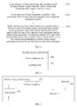
- Step S101 In the absence of data connection, after transmitting N broadcast frame signals with full power, transmit M broadcast frame signals with low power, where M is an integer greater than 0, N is an integer greater than 1 or N is an integer greater than 0, and a sum of M and N remains unchanged in a certain time span.
- the method further includes: detecting a Received Signal Strength Index (RSSI) of each station; and dynamically adjusting values of the parameters N and M according to the RSSI.
- RSSI Received Signal Strength Index
- the RSSI of a received signal is detected, so as to judge a distance between connected station devices. Distribution of the stations is estimated through a statistical method, so as to perform dynamic adjustment. For example, the RSSI of each new station is decided according to a preset threshold X. If the number of stations which satisfy RSSI>X is continuously increased, M increases and N decreases; while if the number of stations which satisfy RSSI ⁇ X is continuously increased, N increases and M decreases.
- a preset threshold X If the number of stations which satisfy RSSI>X is continuously increased, M increases and N decreases; while if the number of stations which satisfy RSSI ⁇ X is continuously increased, N increases and M decreases.
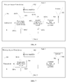
- FIG. 2 the figure in an upper portion of FIG. 2 shows a transmission situation of an AP in the prior art, and the figure in a lower portion of FIG. 2 shows a transmission situation of this embodiment.
- the operating method according to the embodiment of the present invention will change according to an actual situation, and also perform corresponding adjustment on full power transmission and low power transmission.
- the operating method of the wireless AP device provided in the embodiment of the present invention further includes the following steps.
- Step S301 In the presence of data connection, establish a data connection with the lowest transmission rate in all compatible transmission rates.
- Step S302 Judge whether a current transmission rate is greater than or equal to a sum of a current actual throughput and a preset system parameter (here, the preset system parameter is used to indicate a data traffic added on the actual throughput); and if the current transmission rate is smaller than the sum of the current actual throughput and the preset system parameter, increase the transmission rate; while if the current transmission rate is greater than or equal to the sum of the current actual throughput and the preset system parameter, maintain the current transmission rate unchanged.
- a preset system parameter here, the preset system parameter is used to indicate a data traffic added on the actual throughput
- the data connection is established with the lowest transmission rate in all compatible transmission rates to start working. Then, real-time tracking and monitoring are performed to judge whether the current transmission rate is greater than or equal to the sum of the current actual throughput and the preset system parameter. If the current transmission rate is greater than the sum of the current actual throughput and the preset system parameter, it indicates that the current transmission rate can meet the use requirement of a user, and the transmission rate remains unchanged. On the contrary, if the current transmission rate is smaller than the sum of the current actual throughput and the preset system parameter, it indicates that the current transmission rate cannot meet the use requirement of the user, and the transmission rate needs to be increased. In this manner, it is avoided to transmit data with a high transmission rate as in most of the methods and devices in the prior art.
- data transmission is started with the lowest transmission rate, and then the transmission rate is changed at any time according to the actual throughput, thereby avoiding more use of a high-order modulation mode.
- the occupied system resources are reduced, the power consumption is decreased, and the operating time is prolonged when a battery is used for power supply.
- the embodiment of the present invention is also compatible with the judging method in the prior art.
- a wireless Access Point device provided in an embodiment of the present invention includes:
- the above wireless Access Point device further includes:
- a power amplifier works with time intervals, and after N broadcast frame signals are transmitted with full power, M broadcast frame signals are transmitted with low power. Therefore, the power consumption is decreased, and the operating time is prolonged when a battery is used for power supply.
- an existing wireless AP is as shown in FIG. 5 .
- a broadcast frame signal generated by a transceiver 501 is always amplified by a power amplifier 502, and then sent through an antenna 503.
- the power selection unit 401 may be two single-pole double-throw switches in an actual application. The specific is shown in FIG. 6 .
- a first single-pole double-throw switch 601 is disposed between the transceiver 501 and the power amplifier 502.
- a public end 601A of the first single-pole double-throw switch 601 is electrically connected to a signal output end of the transceiver 501, and a first selection end 601B of the first single-pole double-throw switch 601 is electrically connected to a signal input end of the power amplifier 502.
- a second single-pole double-throw switch 602 is disposed between the power amplifier 502 and the antenna 503.
- a first selection end 602B of the second single-pole double-throw switch 602 is electrically connected to a signal output end of the power amplifier 502, and a public end 602A of the second single-pole double-throw switch 602 is electrically connected to the antenna 503 through a switch 504.
- a second selection end 601 C of the first single-pole double-throw switch 601 is electrically connected to a second selection end 602C of the second single-pole double-throw switch 602.
- the path 1 starts from the signal output end of the transceiver 501, passes through the public end 601A of the first single-pole double-throw switch 601, then passes through the first selection end 601B of the first single-pole double-throw switch 601 to reach the signal input end of the power amplifier 502, passes through the power amplifier 502 and exits from the signal output end of the power amplifier 502, passes through the first selection end 602B of the second single-pole double-throw switch 602, then passes through the public end 602A of the second single-pole double-throw switch 602, and reaches the antenna 503 through the switch 504.
- the path 2 starts from the signal output end of the transceiver 501, passes through the public end 601A of the first single-pole double-throw switch 601, then passes through the second selection end 601C of the first single-pole double-throw switch 601 to reach the second selection end 602C of the second single-pole double-throw switch 602, then passes through the public end 602A of the second single-pole double-throw switch 602, and reaches the antenna 503 through the switch 504.
- the path 1 passes through the power amplifier 502, while the path 2 does not pass through the power amplifier 502. Therefore, the broadcast frame signal generated by the transceiver 501 may either be sent from the path 1 or sent from the path 2.
- great power transmission implemented by using the path 1 is referred to as the full power transmission
- transmission implemented by using the path 2 is referred to as the low power transmission.
- the above wireless Access Point device may further include a control unit (not shown) electrically connected to the public end 601A of the first single-pole double-throw switch 601 and the public end 602A of the second single-pole double-throw switch 602.
- the control unit controls the public end 601A of the first single-pole double-throw switch 601 and the public end 602A of the second single-pole double-throw switch 602 to simultaneously switch on the first selection end 601B and 602B, respectively, or simultaneously switch on the second selection end 601C and 602C, respectively. That is, the control unit may control whether the broadcast frame signal generated by the transceiver 501 is transmitted through the path 1 or the path 2.
- the control unit controls the public end 601A and 602A of the first single-pole double-throw switch 601 and the second single-pole double-throw switch 602 to simultaneously switch on the first selection end 601B and 602B of the first single-pole double-throw switch 601 and the second single-pole double-throw switch 602 respectively to transmit N broadcast frame signals
- the control unit controls the public end 601A and 602A of the first single-pole double-throw switch 601 and the second single-pole double-throw switch 602 to simultaneously switch on the second selection end 601C and 602C of the first single-pole double-throw switch 601 and the second single-pole double-throw switch 602 respectively to transmit M broadcast frame signals, where M is an integer greater than 0, N is an integer greater than 1 or N is an integer greater than 0, and the sum of M and N remains unchanged in a certain time span.
- the wireless Access Point device can adjust the transmission power of the broadcast frame signals according to a certain interval ratio, and transmit M broadcast frame signals with low power after N broadcast frame signals are transmitted with full power. Therefore, the power consumption of the wireless Access Point may be greatly decreased, and the operating time of a battery is prolonged. In such a transmission mode, the reserved N broadcast frame signals with full power may ensure that a station device at a farthest end can correctly receive the signals, successfully demodulate related Access Point information, and successfully initiate a connection request to the wireless Access Point device to establish a connection.
- the power selection unit 401 may be one single-pole double-throw switch in an actual application.
- the first single-pole double-throw switch 601 in FIG. 6 is reserved, where the public end 601A of the first single-pole double-throw switch 601 is electrically connected to the signal output end of the transceiver 501, the first selection end 601B of the first single-pole double-throw switch 601 is electrically connected to the signal input end of the power amplifier 502, and the second selection end 601C of the first single-pole double-throw switch 601 is directly electrically connected to a Transmitting/receiving switch 504 and the signal output end of the power amplifier 502, referring to the FIG.
- the second single-pole double-throw switch 602 in FIG. 6 is reserved, where the public end 602A of the second single-pole double-throw switch 602 is electrically connected to the Transmitting/receiving switch 504, the first selection end 602B of the second single-pole double-throw switch 602 is electrically connected to the signal output end of the power amplifier 502, and the second selection end 602C of the second single-pole double-throw switch 602 is directly electrically connected to the transceiver 501 and the signal input end of the power amplifier 502.
- the specific is as shown in FIG. 7 .
- a single-pole double-throw switch 701 is disposed between the transceiver 501 and the power amplifier 502.
- a public end 701A of the single-pole double-throw switch 701 is electrically connected to the signal output end of the transceiver 501
- a first selection end 701B of the single-pole double-throw switch 701 is electrically connected to the signal input end of the power amplifier 502
- a second selection end 701C of the single-pole double-throw switch 701 is electrically connected to a Transmitting/receiving switch 505.
- the path 1 starts from the signal output end of the transceiver 501, passes through the public end 701A of the single-pole double-throw switch 701, then passes through the first selection end 701B of the single-pole double-throw switch 701 to reach the signal input end of the power amplifier 502, and passes through the power amplifier 502 and exits from the signal output end of the power amplifier 502 to reach the antenna 503.
- the path 2 starts from the signal output end of the transceiver 501, passes through the public end 701A of the single-pole double-throw switch 701, then passes through the second selection end 701C of the single-pole double-throw switch 701, and reaches the antenna 503 through the switch 505.
- the path 1 passes through the power amplifier 502, while the path 2 does not pass through the power amplifier 502. Therefore, the broadcast frame signal generated by the transceiver 501 may either be sent from the path 1 or sent from the path 2.
- great power transmission implemented by using the path 1 is referred to as the full power transmission, and transmission implemented by using the path 2 is referred to as the low power transmission.
- the above wireless Access Point device may further include a control unit electrically connected to the single-pole double-throw switch 701.
- the control unit controls the public end 701A of the single-pole double-throw switch 701 to switch on the first selection end 701B or switch on the second selection end 701C. That is, the control unit may control whether the broadcast frame signal generated by the transceiver 501 is transmitted through the path 1 or transmitted through the path 2.
- the control unit controls the public end 701A of the single-pole double-throw switch 701 to switch on the first selection end 701B to transmit N broadcast frame signals
- the control unit controls the public end 701A of the single-pole double-throw switch 701 to switch on the second selection end 701C to transmit M broadcast frame signals, where M is an integer greater than 0, N is an integer greater than 1 or N is an integer greater than 0, and a sum of M and N remains unchanged in a certain time span.
- the wireless Access Point device can adjust the transmission power of the broadcast frame signals according to a certain interval ratio, and transmit M broadcast frame signals with low power after N broadcast frame signals are transmitted with full power. Therefore, the power consumption of the wireless AP may be greatly decreased, and the operating time of a battery is prolonged. In such a transmission mode, the reserved N broadcast frame signals with full power may ensure that a station device at a farthest end can correctly receive the signals, successfully demodulate related AP information, and successfully initiate a connection request to the wireless Access Point device to establish a connection.
- one or two single-pole double-throw switches serving as the power selection unit 401 is merely an example for illustration, and the embodiment of the present invention is not limited thereto.
- Other devices may also be used as the power selection unit 401, which shall fall within the protection scope of the present invention as long as the functions of the devices are the same.
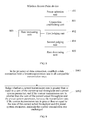
- the wireless Access Point device further includes:
- a first judging unit 802 which is configured to judge whether a current transmission rate is greater than or equal to a sum of a current actual throughput and a preset system parameter.
- a rate increasing unit 803 which is configured to increase the transmission rate if the current transmission rate is smaller than the sum of the current actual throughput and the preset system parameter.
- the wireless Access Point device further includes:
- a rate decreasing unit 805 which is configured to decrease the current transmission rate if the signal strength, the Signal-to-Noise Ratio, or the number of the bad packets in transmission at the current transmission rate fails to meet the normal operation requirement of the current transmission rate.
- an operating method of a wireless Access Point device includes the following steps.
- Step S901 In the presence of data connection, establish a data connection with the lowest transmission rate in all compatible transmission rates.
- Step S902 Judge whether a current transmission rate is greater than or equal to a sum of a current actual throughput and a preset system parameter; and if the current transmission rate is smaller than the sum of the current actual throughput and the preset system parameter, increase the transmission rate; while if the current transmission rate is greater than or equal to the sum of the current actual throughput and the preset system parameter, maintain the current transmission rate unchanged.
- the data connection is established with the lowest transmission rate in all compatible transmission rates to start working. Then, real-time tracking and monitoring are performed to judge whether the current transmission rate is greater than or equal to the sum of the current actual throughput and the preset system parameter. If the current transmission rate is greater than the sum of the current actual throughput and the preset system parameter, it indicates that the current transmission rate can meet the use requirement of a user, and the transmission rate remains unchanged. On the contrary, if the current transmission rate is smaller than the sum of the current actual throughput and the preset system parameter, it indicates that the current transmission rate cannot meet the use requirement of the user, and the transmission rate needs to be increased.
- the method further includes the following steps.
- Step 1001 Judge whether signal strength, an Signal-to-Noise Ratio, or the number of bad packets in transmission at the current transmission rate meets a normal operation requirement of the current transmission rate, and if the signal strength, the Signal-to-Noise Ratio, or the number of the bad packets in transmission at the current transmission rate fails to meet the normal operation requirement of the current transmission rate, decrease the current transmission rate.
- an operating method of a wireless Access Point device provided in another embodiment of the present invention includes the following steps.
- Step 1101 A wireless Access Point device, which may be a wireless AP in this embodiment, establishes a data connection with the lowest transmission rate in all compatible transmission rates.
- Step 1102 The wireless AP performs data transmission with a current transmission rate.
- Step 1103 Judge whether a data transmission process is completed, and if the data transmission process is completed, end the data transmission.
- Step 1104 When the data transmission is not completed, judge whether the current transmission rate is greater than or equal to a sum of a current actual throughput and a preset system parameter.
- Step 1105 If a judgment result is that the current transmission rate is smaller than the sum of the current actual throughput and the preset system parameter, that is, the current transmission rate cannot meet the requirement of a user, increase the data transmission rate.
- Step 1106 If it is determined in step 1104 that the current transmission rate is greater than or equal to the sum of the current actual throughput and the preset system parameter, that is, the current transmission rate can meet the requirement of the user, judge whether signal strength, an SNR, or the number of bad packets in transmission at the current transmission rate meets the requirement of the current transmission rate; and if the signal strength, the SNR, or the number of the bad packets in transmission at the current transmission rate meets the requirement of the current transmission rate, continue the transmission with the transmission rate.
- step 1104 if it is determined in step 1104 that the current transmission rate is smaller than the sum of the current actual throughput and the preset system parameter, that is, the current transmission rate cannot meet the requirement of the user, judge whether signal strength, an SNR, or the number of bad packets in transmission at the transmission rate increased in step 1105 meets a requirement of the current transmission rate; and if the signal strength, the SNR, or the number of the bad packets in transmission at the transmission rate increased in step 1105 meets the requirement of the current transmission rate, continue the transmission with the transmission rate.
- Step 1107 If it is judged in step 1106 that the signal strength, the SNR, or the number of the bad packets in transmission at the current transmission rate fails to meet the requirement of the current transmission rate, decrease the current transmission rate, and perform the transmission with the decreased rate.
- the operating method of the wireless AP of this embodiment is not only compatible with the judgment method in the prior art, but also establishes the data connection with the lowest transmission rate in all compatible transmission rates to start working. Then, real-time tracking and monitoring are performed to judge whether the current transmission rate is greater than or equal to the sum of the current actual throughput and the preset system parameter. If the current transmission rate is greater than the sum of the current actual throughput and the preset system parameter, it indicates that the current transmission rate can meet the use requirement of a user, and the transmission rate remains unchanged. On the contrary, if the current transmission rate is smaller than the sum of the current actual throughput and the preset system parameter, it indicates that the current transmission rate cannot meet the use requirement of the user, and the transmission rate needs to be increased.
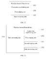
- a wireless Access Point device provided in an embodiment of the present invention includes:
- a first judging unit 1202 which is configured to judge whether a current transmission rate is greater than or equal to a sum of a current actual throughput and a preset system parameter.
- a rate increasing unit 1203, which is configured to increase the transmission rate if the current transmission rate is smaller than the sum of the current actual throughput and the preset system parameter.
- a wireless Access Point device provided in another embodiment of the present invention further includes:
- a rate decreasing unit 1302 which is configured to decrease the current transmission rate if the signal strength, the Signal-to-Noise Ratio, or the number of the bad packets in transmission at the current transmission rate fails to meet the normal operation requirement of the current transmission rate.
Landscapes
- Engineering & Computer Science (AREA)
- Computer Networks & Wireless Communication (AREA)
- Signal Processing (AREA)
- Quality & Reliability (AREA)
- Mobile Radio Communication Systems (AREA)
Applications Claiming Priority (3)
| Application Number | Priority Date | Filing Date | Title |
|---|---|---|---|
| CN2009102085075A CN101742708B (zh) | 2009-10-28 | 2009-10-28 | 无线接入点设备的工作方法及无线接入点设备 |
| PCT/CN2010/078164 WO2011050725A1 (zh) | 2009-10-28 | 2010-10-27 | 无线接入点设备的工作方法及无线接入点设备 |
| EP10826088A EP2496048A4 (de) | 2009-10-28 | 2010-10-27 | Betriebsverfahren für eine drahtlose zugangspunktvorrichtung sowie drahtlose zugangspunktvorrichtung |
Related Parent Applications (1)
| Application Number | Title | Priority Date | Filing Date |
|---|---|---|---|
| EP10826088A Division EP2496048A4 (de) | 2009-10-28 | 2010-10-27 | Betriebsverfahren für eine drahtlose zugangspunktvorrichtung sowie drahtlose zugangspunktvorrichtung |
Publications (2)
| Publication Number | Publication Date |
|---|---|
| EP2858455A1 true EP2858455A1 (de) | 2015-04-08 |
| EP2858455B1 EP2858455B1 (de) | 2019-07-03 |
Family
ID=42465383
Family Applications (2)
| Application Number | Title | Priority Date | Filing Date |
|---|---|---|---|
| EP14194731.7A Active EP2858455B1 (de) | 2009-10-28 | 2010-10-27 | Betriebsverfahren für eine drahtlose Zugangspunktvorrichtung sowie drahtlose Zugangspunktvorrichtung |
| EP10826088A Withdrawn EP2496048A4 (de) | 2009-10-28 | 2010-10-27 | Betriebsverfahren für eine drahtlose zugangspunktvorrichtung sowie drahtlose zugangspunktvorrichtung |
Family Applications After (1)
| Application Number | Title | Priority Date | Filing Date |
|---|---|---|---|
| EP10826088A Withdrawn EP2496048A4 (de) | 2009-10-28 | 2010-10-27 | Betriebsverfahren für eine drahtlose zugangspunktvorrichtung sowie drahtlose zugangspunktvorrichtung |
Country Status (5)
| Country | Link |
|---|---|
| US (1) | US9055485B2 (de) |
| EP (2) | EP2858455B1 (de) |
| JP (2) | JP5583779B2 (de) |
| CN (1) | CN101742708B (de) |
| WO (1) | WO2011050725A1 (de) |
Families Citing this family (12)
| Publication number | Priority date | Publication date | Assignee | Title |
|---|---|---|---|---|
| CN101742708B (zh) * | 2009-10-28 | 2013-01-30 | 华为终端有限公司 | 无线接入点设备的工作方法及无线接入点设备 |
| CN101959296B (zh) * | 2010-02-11 | 2013-10-09 | 华为终端有限公司 | 无线局域接入网的路由设备以及信号发射方法 |
| CN105338588A (zh) * | 2014-07-01 | 2016-02-17 | 杭州华三通信技术有限公司 | 一种调整接入点发射功率的方法及装置 |
| CN104270803B (zh) * | 2014-09-05 | 2018-05-15 | 新华三技术有限公司 | 一种ap工作模式的调整方法和设备 |
| CN104320815B (zh) * | 2014-10-27 | 2017-12-22 | 深圳市蜂联科技有限公司 | 一种用于提高无线局域网络吞吐量的数据传输策略 |
| US9781686B2 (en) | 2015-07-23 | 2017-10-03 | Google Inc. | Reducing wireless communication to conserve energy and increase security |
| JP2017224873A (ja) * | 2016-06-13 | 2017-12-21 | Necプラットフォームズ株式会社 | 通信中継装置、動作設定プログラム及び動作設定方法 |
| KR102420198B1 (ko) | 2017-04-03 | 2022-07-13 | 삼성전자주식회사 | 장치 대 장치 간 통신에서 송신 전력을 제어하기 위한 전자 장치 및 방법 |
| US10601451B1 (en) * | 2019-07-02 | 2020-03-24 | Motorola Mobility Llc | Low-cost method for selectively reducing switch loss |
| CN111624904B (zh) * | 2020-04-07 | 2022-01-18 | 青岛奥利普自动化控制系统有限公司 | 一种基于mes系统的设备管理方法和设备 |
| CN115119324A (zh) * | 2021-03-19 | 2022-09-27 | 华为技术有限公司 | 一种资源调度方法和装置 |
| WO2025238856A1 (ja) * | 2024-05-17 | 2025-11-20 | 株式会社Nttドコモ | 基地局、ネットワークノード、及び通信方法 |
Citations (5)
| Publication number | Priority date | Publication date | Assignee | Title |
|---|---|---|---|---|
| US5857147A (en) * | 1993-09-08 | 1999-01-05 | Qualcom Incorporated | Method and apparatus for determining the transmission data rate in a multi-user communication system |
| US20050094607A1 (en) * | 2003-10-31 | 2005-05-05 | Interdigital Technology Corporation | Adaptive radio resource management for wireless local area networks |
| EP1587221A2 (de) * | 2004-04-16 | 2005-10-19 | Samsung Electronics Co., Ltd. | Senderleistungssteuerung für Netzwerkgeräte in einem drahtlosen lokalen Netzwerk |
| US20050249157A1 (en) * | 2004-05-07 | 2005-11-10 | Lu Qian | Data rate shifting methods and techniques |
| EP1852982A1 (de) * | 2006-05-05 | 2007-11-07 | Broadcom Corporation | Periodische Hochleistungsstufenübertragung unterstützende mehrstufige Zugangspunktübertragungsleistungssteuerung |
Family Cites Families (25)
| Publication number | Priority date | Publication date | Assignee | Title |
|---|---|---|---|---|
| JP2000101605A (ja) * | 1998-09-24 | 2000-04-07 | Sanyo Electric Co Ltd | 赤外線通信装置、赤外線通信方法および記録媒体 |
| EP0991223A1 (de) | 1998-09-30 | 2000-04-05 | Alcatel | Verfahren und Einrichtung für einen schnellen Übergang eines niedrigen Leistungszustandes zu einem hohen Leistungszustand in ein Kommunikationssystem |
| JP2001054165A (ja) * | 1999-08-04 | 2001-02-23 | Nippon Telegr & Teleph Corp <Ntt> | データ通信装置及び方法並びに記録媒体 |
| CN1411258A (zh) * | 2001-10-09 | 2003-04-16 | 英业达集团(南京)电子技术有限公司 | 自动变频传递数据的方法 |
| JP2004215225A (ja) * | 2002-12-17 | 2004-07-29 | Sony Corp | 通信システムおよび通信方法、並びにデータ処理装置 |
| CN1293773C (zh) | 2003-03-26 | 2007-01-03 | 联想(北京)有限公司 | 动态调整无线局域网基站接入点覆盖范围的方法 |
| US7400856B2 (en) * | 2003-09-03 | 2008-07-15 | Motorola, Inc. | Method and apparatus for relay facilitated communications |
| JP4354319B2 (ja) * | 2004-03-26 | 2009-10-28 | Tdk株式会社 | 無線通信装置の制御方法及び無線通信装置 |
| JP2005286642A (ja) * | 2004-03-29 | 2005-10-13 | Nec Corp | 無線lanシステムとそのマルチレート制御方法、及び基地局装置と端末局装置 |
| US7415262B2 (en) * | 2004-03-29 | 2008-08-19 | Intel Corporation | Wireless access point power control |
| JP2006222914A (ja) * | 2005-02-14 | 2006-08-24 | Ntt Docomo Inc | 伝送速度制御方法及び移動局 |
| CN101079643A (zh) * | 2006-05-26 | 2007-11-28 | 摩托罗拉公司 | 减小无线发射机中的功耗的方法和系统 |
| KR20080052142A (ko) * | 2006-12-05 | 2008-06-11 | 한국전자통신연구원 | 전송률 제어 장치 및 방법 |
| CN101365171B (zh) * | 2007-08-10 | 2011-09-21 | 中兴通讯股份有限公司 | 一种专用信道业务传输速率调整方法及装置 |
| US8477674B2 (en) * | 2008-03-12 | 2013-07-02 | Nokia Corporation | Wireless network including post groupcast time |
| US8705484B2 (en) * | 2008-08-15 | 2014-04-22 | Ntt Docomo, Inc. | Method for varying transmit power patterns in a multi-cell environment |
| US20100128645A1 (en) * | 2008-11-26 | 2010-05-27 | Murata Manufacturing Co., Ltd. | System and method for adaptive power conservation based on traffic profiles |
| WO2010065160A1 (en) * | 2008-12-01 | 2010-06-10 | Marvell World Trade Ltd. | Access point enhancements |
| WO2010078476A1 (en) * | 2009-01-02 | 2010-07-08 | Motorola, Inc. | Power control in a multi-layer cellular communication system |
| US8229370B2 (en) * | 2009-03-10 | 2012-07-24 | Minebea Co., Ltd. | Automated power control to optimize power consumption and improved wireless connection |
| US8254978B2 (en) * | 2009-04-02 | 2012-08-28 | Qualcomm Incorporated | Methods and systems for fast power control(FPC) message broadcasting in WiMAX systems |
| CN101541042A (zh) * | 2009-04-24 | 2009-09-23 | 宁波大学 | 一种WiMAX系统的下行调度方法 |
| US8958795B2 (en) * | 2009-05-04 | 2015-02-17 | Qualcomm Incorporated | Proximity based access control |
| WO2011035807A1 (en) * | 2009-09-24 | 2011-03-31 | Nokia Siemens Networks Oy | Method for dynamically controlling an uplink transmission power of a user equipment |
| CN101742708B (zh) * | 2009-10-28 | 2013-01-30 | 华为终端有限公司 | 无线接入点设备的工作方法及无线接入点设备 |
-
2009
- 2009-10-28 CN CN2009102085075A patent/CN101742708B/zh active Active
-
2010
- 2010-10-27 JP JP2012535612A patent/JP5583779B2/ja active Active
- 2010-10-27 EP EP14194731.7A patent/EP2858455B1/de active Active
- 2010-10-27 WO PCT/CN2010/078164 patent/WO2011050725A1/zh not_active Ceased
- 2010-10-27 EP EP10826088A patent/EP2496048A4/de not_active Withdrawn
-
2012
- 2012-04-27 US US13/458,413 patent/US9055485B2/en active Active
-
2014
- 2014-07-16 JP JP2014145888A patent/JP2014197909A/ja active Pending
Patent Citations (5)
| Publication number | Priority date | Publication date | Assignee | Title |
|---|---|---|---|---|
| US5857147A (en) * | 1993-09-08 | 1999-01-05 | Qualcom Incorporated | Method and apparatus for determining the transmission data rate in a multi-user communication system |
| US20050094607A1 (en) * | 2003-10-31 | 2005-05-05 | Interdigital Technology Corporation | Adaptive radio resource management for wireless local area networks |
| EP1587221A2 (de) * | 2004-04-16 | 2005-10-19 | Samsung Electronics Co., Ltd. | Senderleistungssteuerung für Netzwerkgeräte in einem drahtlosen lokalen Netzwerk |
| US20050249157A1 (en) * | 2004-05-07 | 2005-11-10 | Lu Qian | Data rate shifting methods and techniques |
| EP1852982A1 (de) * | 2006-05-05 | 2007-11-07 | Broadcom Corporation | Periodische Hochleistungsstufenübertragung unterstützende mehrstufige Zugangspunktübertragungsleistungssteuerung |
Also Published As
| Publication number | Publication date |
|---|---|
| JP5583779B2 (ja) | 2014-09-03 |
| WO2011050725A1 (zh) | 2011-05-05 |
| JP2014197909A (ja) | 2014-10-16 |
| US9055485B2 (en) | 2015-06-09 |
| EP2496048A4 (de) | 2012-11-07 |
| EP2496048A1 (de) | 2012-09-05 |
| US20120213156A1 (en) | 2012-08-23 |
| EP2858455B1 (de) | 2019-07-03 |
| CN101742708B (zh) | 2013-01-30 |
| JP2013515383A (ja) | 2013-05-02 |
| CN101742708A (zh) | 2010-06-16 |
Similar Documents
| Publication | Publication Date | Title |
|---|---|---|
| US9055485B2 (en) | Operating method of wireless access point device and wireless access point device | |
| US12047813B2 (en) | Methods and apparatus for providing wireless services to a customer premises | |
| EP1943747B1 (de) | Verfahren und vorrichtungen zur steuerung der sendeleistung einer basisstation | |
| US7426385B2 (en) | Communication device and method for communicating over a digital mobile network | |
| EP2579672B1 (de) | Erweiterung für Zeitplanungsanforderungstriggerung basierend auf Verkehrsbedingungen | |
| US20160135144A1 (en) | Method and Apparatus for Heterogeneous Communication | |
| EP3249967B1 (de) | Verfahren und benutzerausrüstung zum anzeigen von verkehrsbezogenen informationen zum netzwerk | |
| EP2941060B1 (de) | Netzwerkzugriffsverfahren, -vorrichtung und -system | |
| EP3804413B1 (de) | Kollaborative bestimmung der drahtlosen signalstärke durch zugangspunkte | |
| KR20100133505A (ko) | 단말기 지원의 wlan 액세스 포인트 속도 적응 | |
| WO2019232262A1 (en) | Load balancing among bands and access points in a wireless network | |
| US7574229B2 (en) | Output power control in multislot uplinks | |
| KR20010073137A (ko) | 기지국 장치, 통신 단말 장치 및 회선 품질 열화 방지 방법 | |
| US11419054B2 (en) | Energy savings on multihomed mobile devices using a dynamically adjusted inactivity timer | |
| WO2010022791A1 (en) | Optimized connection admission control for systems using adaptive modulation and coding techniques | |
| CN102595519B (zh) | 无线接入点设备的工作方法及无线接入点设备 | |
| US20260040287A1 (en) | Application of access point in 6ghz frequency band | |
| CN113905424A (zh) | 一种用于WiFi和蜂窝网络间切换的优化系统和装置 | |
| US8737506B1 (en) | Determination of transmit diversity transmission delays | |
| JP2024064705A (ja) | 移動通信システム、サーバ装置、基地局装置、及びコアネットワーク装置 | |
| CN121568076A (zh) | 一种基于双模通信模组的通信方法及系统 | |
| CN112601273A (zh) | 根据通信模式动态调整射频发射开关的方法及终端 | |
| KR20080075443A (ko) | 무선통신시스템에서 리소스 사용효율을 향상시키는 방법 및장치 | |
| HK1121897A1 (en) | Cell network selectively applying proxy mode to minimize power | |
| HK1126583A (en) | Methods and apparatus for controlling a base station's transmission power |
Legal Events
| Date | Code | Title | Description |
|---|---|---|---|
| PUAI | Public reference made under article 153(3) epc to a published international application that has entered the european phase |
Free format text: ORIGINAL CODE: 0009012 |
|
| 17P | Request for examination filed |
Effective date: 20141125 |
|
| AC | Divisional application: reference to earlier application |
Ref document number: 2496048 Country of ref document: EP Kind code of ref document: P |
|
| AK | Designated contracting states |
Kind code of ref document: A1 Designated state(s): AL AT BE BG CH CY CZ DE DK EE ES FI FR GB GR HR HU IE IS IT LI LT LU LV MC MK MT NL NO PL PT RO RS SE SI SK SM TR |
|
| R17P | Request for examination filed (corrected) |
Effective date: 20151008 |
|
| RBV | Designated contracting states (corrected) |
Designated state(s): AL AT BE BG CH CY CZ DE DK EE ES FI FR GB GR HR HU IE IS IT LI LT LU LV MC MK MT NL NO PL PT RO RS SE SI SK SM TR |
|
| STAA | Information on the status of an ep patent application or granted ep patent |
Free format text: STATUS: EXAMINATION IS IN PROGRESS |
|
| 17Q | First examination report despatched |
Effective date: 20180716 |
|
| RAP1 | Party data changed (applicant data changed or rights of an application transferred) |
Owner name: HUAWEI DEVICE (SHENZHEN) CO., LTD. |
|
| RIC1 | Information provided on ipc code assigned before grant |
Ipc: H04W 28/02 20090101ALN20181204BHEP Ipc: H04W 88/08 20090101AFI20181204BHEP Ipc: H04W 52/32 20090101ALN20181204BHEP Ipc: H04W 28/22 20090101ALI20181204BHEP Ipc: H04W 52/00 20090101ALI20181204BHEP Ipc: H04W 52/02 20090101ALI20181204BHEP Ipc: H04W 52/04 20090101ALI20181204BHEP Ipc: H04L 1/00 20060101ALI20181204BHEP |
|
| RAP1 | Party data changed (applicant data changed or rights of an application transferred) |
Owner name: HUAWEI DEVICE CO., LTD. |
|
| GRAP | Despatch of communication of intention to grant a patent |
Free format text: ORIGINAL CODE: EPIDOSNIGR1 |
|
| STAA | Information on the status of an ep patent application or granted ep patent |
Free format text: STATUS: GRANT OF PATENT IS INTENDED |
|
| RIC1 | Information provided on ipc code assigned before grant |
Ipc: H04W 88/08 20090101AFI20190109BHEP Ipc: H04W 52/00 20090101ALI20190109BHEP Ipc: H04W 28/22 20090101ALI20190109BHEP Ipc: H04W 28/02 20090101ALN20190109BHEP Ipc: H04L 1/00 20060101ALI20190109BHEP Ipc: H04W 52/02 20090101ALI20190109BHEP Ipc: H04W 52/04 20090101ALI20190109BHEP Ipc: H04W 52/32 20090101ALN20190109BHEP |
|
| INTG | Intention to grant announced |
Effective date: 20190129 |
|
| GRAS | Grant fee paid |
Free format text: ORIGINAL CODE: EPIDOSNIGR3 |
|
| GRAA | (expected) grant |
Free format text: ORIGINAL CODE: 0009210 |
|
| STAA | Information on the status of an ep patent application or granted ep patent |
Free format text: STATUS: THE PATENT HAS BEEN GRANTED |
|
| AC | Divisional application: reference to earlier application |
Ref document number: 2496048 Country of ref document: EP Kind code of ref document: P |
|
| AK | Designated contracting states |
Kind code of ref document: B1 Designated state(s): AL AT BE BG CH CY CZ DE DK EE ES FI FR GB GR HR HU IE IS IT LI LT LU LV MC MK MT NL NO PL PT RO RS SE SI SK SM TR |
|
| REG | Reference to a national code |
Ref country code: GB Ref legal event code: FG4D |
|
| REG | Reference to a national code |
Ref country code: CH Ref legal event code: EP Ref country code: AT Ref legal event code: REF Ref document number: 1152545 Country of ref document: AT Kind code of ref document: T Effective date: 20190715 |
|
| REG | Reference to a national code |
Ref country code: IE Ref legal event code: FG4D |
|
| REG | Reference to a national code |
Ref country code: DE Ref legal event code: R096 Ref document number: 602010059901 Country of ref document: DE |
|
| REG | Reference to a national code |
Ref country code: NL Ref legal event code: MP Effective date: 20190703 |
|
| REG | Reference to a national code |
Ref country code: LT Ref legal event code: MG4D |
|
| REG | Reference to a national code |
Ref country code: AT Ref legal event code: MK05 Ref document number: 1152545 Country of ref document: AT Kind code of ref document: T Effective date: 20190703 |
|
| PG25 | Lapsed in a contracting state [announced via postgrant information from national office to epo] |
Ref country code: SE Free format text: LAPSE BECAUSE OF FAILURE TO SUBMIT A TRANSLATION OF THE DESCRIPTION OR TO PAY THE FEE WITHIN THE PRESCRIBED TIME-LIMIT Effective date: 20190703 Ref country code: BG Free format text: LAPSE BECAUSE OF FAILURE TO SUBMIT A TRANSLATION OF THE DESCRIPTION OR TO PAY THE FEE WITHIN THE PRESCRIBED TIME-LIMIT Effective date: 20191003 Ref country code: NL Free format text: LAPSE BECAUSE OF FAILURE TO SUBMIT A TRANSLATION OF THE DESCRIPTION OR TO PAY THE FEE WITHIN THE PRESCRIBED TIME-LIMIT Effective date: 20190703 Ref country code: AT Free format text: LAPSE BECAUSE OF FAILURE TO SUBMIT A TRANSLATION OF THE DESCRIPTION OR TO PAY THE FEE WITHIN THE PRESCRIBED TIME-LIMIT Effective date: 20190703 Ref country code: PT Free format text: LAPSE BECAUSE OF FAILURE TO SUBMIT A TRANSLATION OF THE DESCRIPTION OR TO PAY THE FEE WITHIN THE PRESCRIBED TIME-LIMIT Effective date: 20191104 Ref country code: LT Free format text: LAPSE BECAUSE OF FAILURE TO SUBMIT A TRANSLATION OF THE DESCRIPTION OR TO PAY THE FEE WITHIN THE PRESCRIBED TIME-LIMIT Effective date: 20190703 Ref country code: HR Free format text: LAPSE BECAUSE OF FAILURE TO SUBMIT A TRANSLATION OF THE DESCRIPTION OR TO PAY THE FEE WITHIN THE PRESCRIBED TIME-LIMIT Effective date: 20190703 Ref country code: FI Free format text: LAPSE BECAUSE OF FAILURE TO SUBMIT A TRANSLATION OF THE DESCRIPTION OR TO PAY THE FEE WITHIN THE PRESCRIBED TIME-LIMIT Effective date: 20190703 Ref country code: CZ Free format text: LAPSE BECAUSE OF FAILURE TO SUBMIT A TRANSLATION OF THE DESCRIPTION OR TO PAY THE FEE WITHIN THE PRESCRIBED TIME-LIMIT Effective date: 20190703 Ref country code: NO Free format text: LAPSE BECAUSE OF FAILURE TO SUBMIT A TRANSLATION OF THE DESCRIPTION OR TO PAY THE FEE WITHIN THE PRESCRIBED TIME-LIMIT Effective date: 20191003 |
|
| PG25 | Lapsed in a contracting state [announced via postgrant information from national office to epo] |
Ref country code: LV Free format text: LAPSE BECAUSE OF FAILURE TO SUBMIT A TRANSLATION OF THE DESCRIPTION OR TO PAY THE FEE WITHIN THE PRESCRIBED TIME-LIMIT Effective date: 20190703 Ref country code: GR Free format text: LAPSE BECAUSE OF FAILURE TO SUBMIT A TRANSLATION OF THE DESCRIPTION OR TO PAY THE FEE WITHIN THE PRESCRIBED TIME-LIMIT Effective date: 20191004 Ref country code: IS Free format text: LAPSE BECAUSE OF FAILURE TO SUBMIT A TRANSLATION OF THE DESCRIPTION OR TO PAY THE FEE WITHIN THE PRESCRIBED TIME-LIMIT Effective date: 20191103 Ref country code: ES Free format text: LAPSE BECAUSE OF FAILURE TO SUBMIT A TRANSLATION OF THE DESCRIPTION OR TO PAY THE FEE WITHIN THE PRESCRIBED TIME-LIMIT Effective date: 20190703 Ref country code: RS Free format text: LAPSE BECAUSE OF FAILURE TO SUBMIT A TRANSLATION OF THE DESCRIPTION OR TO PAY THE FEE WITHIN THE PRESCRIBED TIME-LIMIT Effective date: 20190703 Ref country code: AL Free format text: LAPSE BECAUSE OF FAILURE TO SUBMIT A TRANSLATION OF THE DESCRIPTION OR TO PAY THE FEE WITHIN THE PRESCRIBED TIME-LIMIT Effective date: 20190703 |
|
| PG25 | Lapsed in a contracting state [announced via postgrant information from national office to epo] |
Ref country code: TR Free format text: LAPSE BECAUSE OF FAILURE TO SUBMIT A TRANSLATION OF THE DESCRIPTION OR TO PAY THE FEE WITHIN THE PRESCRIBED TIME-LIMIT Effective date: 20190703 |
|
| PG25 | Lapsed in a contracting state [announced via postgrant information from national office to epo] |
Ref country code: DK Free format text: LAPSE BECAUSE OF FAILURE TO SUBMIT A TRANSLATION OF THE DESCRIPTION OR TO PAY THE FEE WITHIN THE PRESCRIBED TIME-LIMIT Effective date: 20190703 Ref country code: EE Free format text: LAPSE BECAUSE OF FAILURE TO SUBMIT A TRANSLATION OF THE DESCRIPTION OR TO PAY THE FEE WITHIN THE PRESCRIBED TIME-LIMIT Effective date: 20190703 Ref country code: RO Free format text: LAPSE BECAUSE OF FAILURE TO SUBMIT A TRANSLATION OF THE DESCRIPTION OR TO PAY THE FEE WITHIN THE PRESCRIBED TIME-LIMIT Effective date: 20190703 Ref country code: IT Free format text: LAPSE BECAUSE OF FAILURE TO SUBMIT A TRANSLATION OF THE DESCRIPTION OR TO PAY THE FEE WITHIN THE PRESCRIBED TIME-LIMIT Effective date: 20190703 Ref country code: PL Free format text: LAPSE BECAUSE OF FAILURE TO SUBMIT A TRANSLATION OF THE DESCRIPTION OR TO PAY THE FEE WITHIN THE PRESCRIBED TIME-LIMIT Effective date: 20190703 |
|
| PG25 | Lapsed in a contracting state [announced via postgrant information from national office to epo] |
Ref country code: SM Free format text: LAPSE BECAUSE OF FAILURE TO SUBMIT A TRANSLATION OF THE DESCRIPTION OR TO PAY THE FEE WITHIN THE PRESCRIBED TIME-LIMIT Effective date: 20190703 Ref country code: MC Free format text: LAPSE BECAUSE OF FAILURE TO SUBMIT A TRANSLATION OF THE DESCRIPTION OR TO PAY THE FEE WITHIN THE PRESCRIBED TIME-LIMIT Effective date: 20190703 Ref country code: SK Free format text: LAPSE BECAUSE OF FAILURE TO SUBMIT A TRANSLATION OF THE DESCRIPTION OR TO PAY THE FEE WITHIN THE PRESCRIBED TIME-LIMIT Effective date: 20190703 Ref country code: IS Free format text: LAPSE BECAUSE OF FAILURE TO SUBMIT A TRANSLATION OF THE DESCRIPTION OR TO PAY THE FEE WITHIN THE PRESCRIBED TIME-LIMIT Effective date: 20200224 |
|
| REG | Reference to a national code |
Ref country code: CH Ref legal event code: PL |
|
| REG | Reference to a national code |
Ref country code: DE Ref legal event code: R097 Ref document number: 602010059901 Country of ref document: DE |
|
| PLBE | No opposition filed within time limit |
Free format text: ORIGINAL CODE: 0009261 |
|
| STAA | Information on the status of an ep patent application or granted ep patent |
Free format text: STATUS: NO OPPOSITION FILED WITHIN TIME LIMIT |
|
| PG2D | Information on lapse in contracting state deleted |
Ref country code: IS |
|
| PG25 | Lapsed in a contracting state [announced via postgrant information from national office to epo] |
Ref country code: LU Free format text: LAPSE BECAUSE OF NON-PAYMENT OF DUE FEES Effective date: 20191027 Ref country code: LI Free format text: LAPSE BECAUSE OF NON-PAYMENT OF DUE FEES Effective date: 20191031 Ref country code: CH Free format text: LAPSE BECAUSE OF NON-PAYMENT OF DUE FEES Effective date: 20191031 |
|
| 26N | No opposition filed |
Effective date: 20200603 |
|
| REG | Reference to a national code |
Ref country code: BE Ref legal event code: MM Effective date: 20191031 |
|
| PG25 | Lapsed in a contracting state [announced via postgrant information from national office to epo] |
Ref country code: SI Free format text: LAPSE BECAUSE OF FAILURE TO SUBMIT A TRANSLATION OF THE DESCRIPTION OR TO PAY THE FEE WITHIN THE PRESCRIBED TIME-LIMIT Effective date: 20190703 Ref country code: BE Free format text: LAPSE BECAUSE OF NON-PAYMENT OF DUE FEES Effective date: 20191031 |
|
| PG25 | Lapsed in a contracting state [announced via postgrant information from national office to epo] |
Ref country code: IE Free format text: LAPSE BECAUSE OF NON-PAYMENT OF DUE FEES Effective date: 20191027 |
|
| PG25 | Lapsed in a contracting state [announced via postgrant information from national office to epo] |
Ref country code: CY Free format text: LAPSE BECAUSE OF FAILURE TO SUBMIT A TRANSLATION OF THE DESCRIPTION OR TO PAY THE FEE WITHIN THE PRESCRIBED TIME-LIMIT Effective date: 20190703 |
|
| PG25 | Lapsed in a contracting state [announced via postgrant information from national office to epo] |
Ref country code: MT Free format text: LAPSE BECAUSE OF FAILURE TO SUBMIT A TRANSLATION OF THE DESCRIPTION OR TO PAY THE FEE WITHIN THE PRESCRIBED TIME-LIMIT Effective date: 20190703 Ref country code: HU Free format text: LAPSE BECAUSE OF FAILURE TO SUBMIT A TRANSLATION OF THE DESCRIPTION OR TO PAY THE FEE WITHIN THE PRESCRIBED TIME-LIMIT; INVALID AB INITIO Effective date: 20101027 |
|
| PG25 | Lapsed in a contracting state [announced via postgrant information from national office to epo] |
Ref country code: MK Free format text: LAPSE BECAUSE OF FAILURE TO SUBMIT A TRANSLATION OF THE DESCRIPTION OR TO PAY THE FEE WITHIN THE PRESCRIBED TIME-LIMIT Effective date: 20190703 |
|
| PGFP | Annual fee paid to national office [announced via postgrant information from national office to epo] |
Ref country code: GB Payment date: 20230907 Year of fee payment: 14 |
|
| PGFP | Annual fee paid to national office [announced via postgrant information from national office to epo] |
Ref country code: FR Payment date: 20230911 Year of fee payment: 14 |
|
| GBPC | Gb: european patent ceased through non-payment of renewal fee |
Effective date: 20241027 |
|
| PG25 | Lapsed in a contracting state [announced via postgrant information from national office to epo] |
Ref country code: GB Free format text: LAPSE BECAUSE OF NON-PAYMENT OF DUE FEES Effective date: 20241027 |
|
| PG25 | Lapsed in a contracting state [announced via postgrant information from national office to epo] |
Ref country code: FR Free format text: LAPSE BECAUSE OF NON-PAYMENT OF DUE FEES Effective date: 20241031 |
|
| PGFP | Annual fee paid to national office [announced via postgrant information from national office to epo] |
Ref country code: DE Payment date: 20250902 Year of fee payment: 16 |