EP2858472B1 - Dispositif d'épandage pour matériel granulaire, en particulier dispositif à semer - Google Patents
Dispositif d'épandage pour matériel granulaire, en particulier dispositif à semer Download PDFInfo
- Publication number
- EP2858472B1 EP2858472B1 EP13734975.9A EP13734975A EP2858472B1 EP 2858472 B1 EP2858472 B1 EP 2858472B1 EP 13734975 A EP13734975 A EP 13734975A EP 2858472 B1 EP2858472 B1 EP 2858472B1
- Authority
- EP
- European Patent Office
- Prior art keywords
- housing
- paddle
- grains
- conveying
- seeds
- Prior art date
- Legal status (The legal status is an assumption and is not a legal conclusion. Google has not performed a legal analysis and makes no representation as to the accuracy of the status listed.)
- Not-in-force
Links
Images





Classifications
-
- A—HUMAN NECESSITIES
- A01—AGRICULTURE; FORESTRY; ANIMAL HUSBANDRY; HUNTING; TRAPPING; FISHING
- A01C—PLANTING; SOWING; FERTILISING
- A01C7/00—Sowing
- A01C7/04—Single-grain seeders with or without suction devices
-
- A—HUMAN NECESSITIES
- A01—AGRICULTURE; FORESTRY; ANIMAL HUSBANDRY; HUNTING; TRAPPING; FISHING
- A01C—PLANTING; SOWING; FERTILISING
- A01C7/00—Sowing
- A01C7/04—Single-grain seeders with or without suction devices
- A01C7/042—Single-grain seeders with or without suction devices using pneumatic means
Definitions
- the present invention relates to a distribution unit for granular material such as seeds, fertilizer o. The like. It relates in particular to a sowing unit with the features of independent claim 1.
- Distribution devices for granular material, in particular seed drills are known in numerous design variants.
- the grain is conveyed by means of an air flow to which the grains are metered.
- the serving as a carrier medium air flow is supplied to a manifold that can open into a plurality of hose lines, which can eventually end in juxtaposed crowds of seeder.
- the dosage of the grains allows the variation of the volume flow of applied grains.
- Other ways to influence the dosage of the grains in the individual lines that lead to the droves usually do not exist.
- the grains can be fed regularly to the air flow. However, the consistency of the grain feed during air-assisted transport is more or less affected, so that the grain deposition on the coulters often uneven, which can lead to disadvantages in the stand allocation of individual plants.
- a device for stabilizing a good flow of a drill or seeder is from the DE 196 36 787 C1 known.
- it is intended to stabilize the particle, granule or grain distances in the region of a volumetric grain conveying, so that the grains can be deposited in extensive separation.
- the grain conveying in a she liber after a metering unit or in the coulter takes place via a cascade composed of channels cascade or - Unit. or a distribution channel, over which the particles or grains are separated and strung by repeated changes of direction.
- the discharge line should be designed as a multi-part distribution line, the individual line elements are each arranged obliquely to each other that the individual particles arranged by the influence of gravity behind one another and flow out in a zig-zag, at least the end-side conduit element has a channel-shaped cross-section.
- a device which can be used universally for different grain sizes and types of seeds for separating and dispensing granular material, in particular a single-grain sowing device, is furthermore disclosed in US Pat DE 36 33 955 A1 disclosed.
- a rotating narrow hollow cylinder with cell-forming recesses at its open End face, a fixed outer cover and a disposed within the hollow cylinder cover ring proposed.
- a reservoir is separated from the hollow cylinder by a wall having an opening for the passage of a limited amount of material to be separated.
- a length of the recesses forming the cells should be two or more times the length of the grains to be separated.
- a suction opening is provided near a rear boundary surface of the recesses.
- the rapidly rotating hollow cylinder picks up a few grains per recess from the grain supply, with the outer cover covering the recesses in the filling zone and preventing the grains from falling out.
- the centrifugal force pushes the grains into the recesses while a brush scraper removes excess grains that fall back into the supply.
- An additional pneumatic wiper can support this grain singling. At the point of discharge, the negative pressure is cut off, so that the grains are discharged from the recesses by centrifugal force and gravity.
- the DE 38 22 437 A1 also discloses a Gutleit adopted for such Einzelkornsä painen that should ensure that excess Gutteilchen stripped from the recesses and deflected in such a way that they are completely supplied to the stock of goods.
- FIG. 1 Another Einzelkorndosiervorraum for Einzelkornaussaat of grain is from the DE 41 16 724 A1 known.
- moving singling openings for adding individual grains are formed by spoon-shaped openings in a thin-walled lateral surface of a rotating cylinder open to one side.
- the spoon-shaped openings overlap with a slot of a housing enclosing the cylinder, from which the suction openings for sucking and for the occasional transport of the seeds are formed.
- the DE 22 17 513 C3 discloses a single grain metering device with a rotating distributor disc having two annular rings with openings for aspirating individual grains. A scraper ensures that only one hole of an opening pair of the two rings is loaded with a grain, which can then be discharged.
- the CN 100 998 281 B discloses a Verteilaggregat according to the preamble of claim 1.
- the known metering devices are either modified Einzelkornsäaggregate, although allow precise grain separation, but limited in their processing capacity and in their grain volume flow over volumetric metering seed drills and / or are complex and prone to failure in their structure and function.
- the known accessories which are intended to improve the regular delivery of seeds in volumetric metering machines, however, do not reach the singulation quality of conventional Einzelkornsäaggregate zoom.
- a primary object of the invention is to improve the delivery accuracy and / or the grain distances in a volumetric grain promotion so far that it approaches the Korndosierung in terms of their singling quality of a single-grain metering or ideally achieved this, while a high grain volume flow should be possible.
- These specifications are intended to be achieved with a simple, robust and interference-prone design, and a simple function characteristic of volumetric metering seed drills.
- the object of the invention is achieved with the subject matter of the independent claim.
- a distribution unit for granular material such as seeds, fertilizer o. The like.
- the distribution unit according to the invention comprises a housing in a cylindrical shape with at least one inlet opening for receiving and for transporting granular material or transported seeds and an outlet opening for discharging the granular Guts or the seeds at substantially regular intervals from each other.
- the unit comprises a conveyor located in the housing with at least one rotating, approximately axially and radially arranged to the inside of the housing or extending conveyor element for detecting, handling, promotion and / or alignment or grouping of the granular material or the seeds.
- the grains are preferably directed at a certain speed into the housing so that they can be steered, passed and placed in regular arrangement after passing through the inlet opening with the aid of the resulting centrifugal forces and the inner housing design. So the grains are using the speed-related centrifugal forces on an inner shell region of the housing held and can crowd there and align against each other and in a line arrange or line up at an angle corresponding to an angular position between the lateral surface and the radial conveying element.
- the goal of this alignment is to discharge at the end of this array only a single grain through the outlet opening, wherein the respective following grains are always released at largely constant intervals and / or grain intervals and discharged from the housing.
- the arrangement and grouping of the grains rapidly conveyed through the housing furthermore leads to them being guided in a predefined path along the lateral surface of the inner side of the housing and leaving the outlet opening approximately tangentially at the end of the singulation process.
- linear grain orientation may, in particular, mean a grain orientation parallel to the surface of the conveyor element or parallel to the longitudinal extension direction of the housing.
- the housing may in particular have a cylindrical, optionally also a unilaterally tapered inner circumferential surface.
- other housing contours are conceivable, for example. An elliptical or with other contour tapering or widening inside the housing.
- the inner surface of the housing should have no pronounced steps or edges, which could oppose the grain transport or the grain flow increased resistance.
- a preferred embodiment of the distribution unit according to the invention is acted upon by an air flow guided through the inlet opening, which at the same time conveys the granular material or the seeds and also leaves the housing again through the outlet opening.
- This air flow also serves to keep the grains in the housing in motion and to steer and convey on their intended path.
- the grains can be fed from a central container through the inlet.
- smaller intermediate containers can be provided for the grains, which are assigned to each distribution or separation unit.
- the metered addition of the grains to the carrying air stream can also take place.
- the air flow, with which the grains are brought then passes through the doser or the aggregate and carries the delivered grains in or after delivery on.
- the air flow can advantageously ensure that the grains can continue to flow through the meter even when the conveyor element is at a standstill with the carrying air flow.
- the grain conveying may also be purely mechanical, in particular by the rotational movement of the conveying element, which forces the grains within the housing in a circular or spiral movement and thereby provides the desired separation when the grains discharged through the outlet opening become.
- the rotating conveyor element may in particular have an electric motor drive, which allows an adjustment of the rotational speed as needed.
- Each conveyed grain passes through the outlet before the grain discharge a circular motion or a spiral path of movement which covers an angle of at least 360 degrees, being held by the at least one conveying element on an approximately cylindrical or conically shaped lateral surface and at the same time a slight axial Feed in the direction of the grain output at the outlet learns.
- it makes sense if the feeding of the grains at least in the region of the outlet opening for the last grain -. for the just released grain - is given by a leading contour.
- Verteilaggregats has proven, in which the inner circumferential surface of the housing has a structuring in the form of a continuous spiral or track, which extends from one end face to the opposite end side or a portion thereof.
- this spiral-like structuring may have a continuous constant pitch or also sections of respectively different pitches, wherein the pitch towards the outlet opening is preferably greater than in the area of the inlet opening.
- the groove width formed thereby resulting from this patterning may usefully be tuned to the grain size so that the grains through the helical grooves formed with the patterning, as it were be steered and guided until they pass one by one the outlet opening.
- the structuring may also be narrower or have a smaller pitch, since there As a rule, the grains aggregate more strongly anyway and form a kind of buffer, so that a direct steering of each individual grain on the guideway formed by the structuring is not equally required as in the direction of the grain outlet.
- the cleaning effect of the structuring has been found because it can effectively prevent the adhesion and retention of impurities and foreign substances. While such foreign matter as, for example, grass blades on a smooth, unstructured wall are difficult to take along, the structuring in connection with the constant grain movement ensures the entrainment of all such impurities and foreign matter, so that they are discharged from the housing without further disturbances.
- a characteristic feature of the distributor is that almost all the grains in the dispenser are in motion, this movement being effected by the conveyor and / or the air flow. Due to its special type of grain conveying, the dosing device is able to easily compensate for short fluctuations or irregularities in the grain inflow and thus to fulfill a buffer function if the grain volume flow in the feeder fluctuates or suddenly decreases.
- a concrete embodiment of the granular material distribution unit according to the invention such as seeds, fertilizer o.
- the like. which may be in particular a sowing unit of a distributor or seeder, has a housing with a cylindrical inner surface and at least one opening therein opening for an air flow and granular material conveyed therein on.
- the housing rotates concentrically a conveyor for the carried in the air flow granular material and promotes this to at least one outlet opening, which connects approximately tangentially to the inner circumferential surface.
- the conveying device has at least one paddle-like conveying element which strikes along the inner lateral surface.
- the inner circumferential surface of the housing has a structuring in the form of a continuous spiral, which extends from one end face to the opposite end face.
- the spiral-like structuring is directed in the direction of rotation of the conveyor in the direction of the outlet opening and opens there.
- the spiral-like structuring begins in the direction of rotation of the conveyor in the region of the inlet opening and thus connects the inlet and the outlet opening, so that the grains carried by the air flow pass through the inlet opening, ordered by the conveyor in conjunction with the spiral-like structuring of the walls and made uniform and finally leave the outlet as a largely uniform crop flow of grains.
- a further variant of the distribution unit according to the invention provides that a longitudinal side of the at least one paddle-like conveying element extends parallel to the longitudinal direction of the housing, wherein a narrow side of the conveying element is usually shorter than the longitudinal side and, for example. Measures less than half of the inner diameter of the housing.
- the rotary conveyor may comprise two, three, four or more similar or differently shaped paddle-like conveying elements, each equally spaced from each other on a central shaft.
- the paddle-like conveying elements can each be resiliently suspended (if necessary also resiliently) on the central shaft, so that they can escape with increased resistance.
- the grain conveying may possibly be improved by the fact that the at least one paddle-like conveying element has a concave curvature in the direction of rotation.
- the at least one paddle-like conveying element has a small distance to the inner circumferential surface of the housing, which is smaller than half of the smallest grain diameter of the spreading material to be delivered.
- the distance of the conveyor elements or conveyor paddle to the wall should not be less than a minimum to prevent Klemmerscheinept, especially in the case of foreign matter or impurities in the housing. However, the distance should not be too large, so that no grains between the housing wall and the outer peripheral edge of the conveying elements or paddles advised and can be trapped there, which could lead to disturbances in grain transport and congestion.
- One Distance of about 0.2 to 0.5 mm to the wall, in particular of about 0.3 mm has proven to be suitable in practice.
- the at least one paddle-like conveying element in the interest of a high distribution and separation quality should extend in its width over part of the outlet opening so that it is swept over by the rotating conveyor.
- the speed of rotation and the number of paddle-like conveying elements expediently depend on the respectively extracted and separated seed.
- the use of a single conveying element or conveying paddle has proven to be useful for sowing rapeseed, which should also rotate relatively slowly.
- sowing wheat have two oppositely arranged conveying elements or redesignpaddel that rotate relatively quickly - eg. With a frequency of about 25 to 50 Hz - proven to be a useful construction variant. With two conveying elements, this results in a grain frequency in the delivery of about 50 to 100 Hz.
- a central shaft of the conveyor may, for example, be driven by an electric motor.
- the paddle-like conveying elements can be driven in a simple drive variant of the conveyor via the air flow through the inlet opening into the housing.
- the paddles can be driven by an electric motor for a higher delivery accuracy, wherein in the interest of a constant and equidistant grain output modulation of the drive speed is not desirable, but only an adaptation to the driving speed of the associated carrier machine (eg the drill).
- the conveyor ensures only the air flow that enters through the inlet opening in the housing and carries the grains for driving the conveyor or the conveyor elements, which inevitably with a loss of storage accuracy connected is. However, this can be acceptable depending on the application and at least partially offset by the very simple and inexpensive construction of the sowing unit, which in this case comprises only a very few parts.
- the invention also includes a multi-row distribution machine for granular material such as seeds, fertilizer or the like, in particular a distribution or seed drill which has a plurality of juxtaposed distribution units according to one of the embodiments described above.
- the inner circumferential surface in which the conveyor rotates, does not necessarily have to be cylindrically shaped, but can also taper on one side.
- the conveying elements of the rotating conveyor can be adapted with a corresponding inclination to such a conical inner surface, that their distance from the wall is uniformly small.
- the spiral-shaped structuring of the inner circumferential surface may also be adapted to such a shape or, depending on the embodiment, may also be missing, wherein the pitch of the structuring may remain constant over the conically tapering inner diameter of the housing. Irrespective of the shaping of the inner circumferential surface, it may be useful to adapt the pitch or dimensioning of the structuring to the grain sizes typically used and / or to the volume flow of conveyed grains.
- the inner lateral surface can also be cylindrical and have a smooth, non-structured inner casing, wherein a conveying direction of the grain good is to be ensured solely by the air flow and / or by a slight inclination of the conveying element (for example a slight screw shape).
- the distribution unit defined by the present invention serves as uniform as possible and as required or configuration or mode of operation also the isolated delivery of granular material such as seeds, fertilizer, etc.
- a distribution unit so thus usually meant a sowing unit of a distribution or seed drill.
- sowing machine several similar sowing units are usually arranged side by side, so that a multi-row sowing is possible.
- Verteilaggregats or Saggregats each comprise a cylindrical housing with a cylindrical inner surface and an opening into the housing inlet opening for an air flow transported by this and transported into the housing granular material or seeds.
- the cylindrical housing may have an elongated shape such that the length of the cylindrical shape is greater than the diameter of the housing.
- the housing may also be made relatively short, so that its diameter may possibly be greater than its length between the end faces of the cylindrical shape.
- the inlet opening opens tangentially at one of the two opposite end faces of the cylinder formed by the housing into the housing, so that the air flow can also enter tangentially into the housing interior.
- a connecting piece o. The like.
- the housing which is the end face opposite the inlet opening, there is an outlet opening of the distribution or sowing unit, which in turn is arranged tangentially to the cylindrical inner surface of the housing, so that the inlet opening and the outlet or discharge opening either parallel to each other are arranged or that at least their central axes lie in parallel planes.
- the sowing or Verteilaggregat invention comprises an aid that facilitates or improves the homogenization of the registered in the flow of air into the housing interior Verteilgut or carried by the air flow of seeds.
- a rotating there conveyor inside the housing, which can rotate concentrically in the housing or concentric with the cylindrical housing inner surface.
- the rotating conveyor serves not only the transport of the carried in the air flow granular material or of the Air flow transported seeds, but also the homogenization of the goods or grain transport within the housing, as its rotation on the one hand brakes the grains that are too fast, but on the other hand also entrains and accelerates those grains that are braked strongly within the housing.
- the flowing into the housing through the inlet opening air flow and the rotating conveyor promote the seeds to the outlet opening, which connects approximately tangentially to the inner surface of the housing and the example.
- a coulter o. The like. Lead or there can lead.
- the conveying device can have a plurality of paddle-like conveying elements which strike along the inner lateral surface of the housing and which are fastened opposite to a shaft which rotates concentrically in the housing.
- at least one such paddle-like conveying element is present, which rotates in the housing, wherein no sliding contact of the conveying element with the Gescouseinnenmantel components makes sense, but a slight distance, but should not let pass any grains.
- two, three or four such paddle-like conveying elements are arranged on the shaft, each uniformly spaced or evenly distributed.
- the conveyor is normally not formed by closed blades, which form the conveying elements in a star-shaped arrangement, but rather has conveying elements which have a parallel or slightly inclined to the central axis of the conveyor arranged slide portion which reaches almost to the inner circumferential surface of the cylindrical housing.
- the length of the conveyor may optionally be designed so that the mouth region of the air inlet is not or only partially swept over, so that the conveying elements is spaced apart from the edge of the corresponding end face of the housing. Such a design can improve the distribution of the grains in the housing interior.
- the conveying elements may optionally sweep the outlet opening, since there the grains are to be discharged equidistantly from the housing, which is facilitated by a uniformly rotating conveyor and correspondingly uniformly over the outlet stroking conveyor elements.
- the paddle-like conveying elements of the conveyor ensure distribution and equalization of the crop flow to grains, which may tend to accumulate in the vicinity of the inlet opening, but are ideally lined up by the rotating movement of the conveying elements in such a way that the Grains singly and at regular intervals and in constant dispensing direction discharged through the outlet opening, whereby the object of the present invention - the equalization of a flow for the individual delivery of grains - can be largely fulfilled.
- the rotating within the housing conveyor can optionally be offset by means of the entering through the inlet opening into the housing of the distribution unit air flow in rotation, so have a passive drive.
- the conveyor rotated by an external drive, optionally in controllable speed of rotation.
- an electric motor drive can be suitable, which can be arranged on the outside of the housing of the Verteilaggregats.
- hydrostatic drives or belt drives with central drive motor are conceivable.
- Another useful option of the present invention may be to provide the inner circumferential surface of the housing with a structuring in the form of a continuous spiral.
- a structuring in the form of a continuous spiral.
- Such a helical structuring can, for example, from a first end face, on which the connecting piece is arranged with the inlet opening, to the opposite end face on which the outlet opening is located rich.
- this optional spiral-like structuring is directed in the direction of rotation of the conveyor in the direction of the outlet opening and opens there.
- the spiral-like structuring can thus begin in the direction of rotation of the conveyor in the region of the inlet opening and thus connects the inlet opening with the outlet opening, so that the grains carried by the air flow pass through the inlet opening through the connecting piece, of the paddle-like conveying elements of the rotating conveyor in conjunction with the ordered spiral-like structuring of the walls and evened out and finally leave the outlet as a largely uniform and ideally isolated product stream of seeds.
- the aforementioned spiral-like structuring may optionally have different pitch sections and be divided into a deceleration and separation windings.
- the delay thread provided with a smaller thread pitch is located near the inlet and at the first end face, while the adjoining separating thread can have a greater pitch in the direction of the outlet and the second end face, so that the individual threads have a width approximately equal to the width Diameter of the grains to be separated corresponds, so that they are guided in the threads.
- Other designs are conceivable, for example, a structuring, in a defined distance begins from the inlet end of the housing and / or not quite extends to the opposite end side and / or has variable groove depths, etc.
- the uniformly rotating paddle-like conveying elements of the conveyor in connection with the running through the housing uniform air flow and possibly the optional to be understood spiral structuring of the inner surface of the housing effect a homogenization of the crop (on grains, seeds, etc.) which ideally leads to an equidistant delivery of the grains or the granular material at the outlet.
- the sowing or Verteilaggregat invention provides a uniform grain separation high quality, if not too many grains are transported in the air flow or a too high speed applied to the rotating shaft.
- the grain conveying or the grain transport may still be partially disordered, so that an optimal distribution of all grains on the respective conveying elements has not yet been achieved.
- Some of the grains are typically still uncontrollably swirled around in the housing, wherein they are normally all located on the inner circumferential surface due to the centrifugal forces acting after passing through the inlet opening and there perform a circular or spiral movement in the direction of rotation of the shaft. After multiple circular movements and approach to the outlet usually no grains are in the housing, which are not moved by the conveyor elements and rest there so that they in ideal tangential movement as a single stream through the outlet opening downwards (or depending on the direction Outlet opening obliquely or horizontally) are discharged from the housing.
- This ramp may optionally have a rectilinear course and provide for a tangential grain movement through the outlet opening.
- the ramp may in principle be shaped differently and, for example, have a curved in the direction of the central axis of the housing course, which can deflect the grains after the tangential detachment movement in an axial movement, for example.
- Parallel to the longitudinal direction of the housing extends. Basically, the grains can be impressed in this way almost any direction in which they can leave the case.
- the design of the paddle-like conveyor elements ensures a sufficient free cross-section in the housing interior between the inlet opening and the outlet opening so that, if necessary, a portion of the conveyed grains may be guided past the conveying elements between the central shaft and the clearance between the shaft and the conveying elements disposed thereon, whereby the grains can leave the housing through the outlet.
- the longitudinal sides of the paddle-like conveying elements extend approximately parallel to the longitudinal direction of the housing and the shaft and thereby have a width extending over several tracks or grooves of the spiral-shaped structuring extends.
- the radially extending in the housing narrow sides of the conveying elements are significantly shorter than the longitudinal sides and measure less than one third of the inner diameter of the housing in the illustrated embodiment.
- the conveying elements of the rotating conveyor may have a slightly helical course in a direction parallel to the shaft, whereby the axial feed of the grains is given in the direction of the housing outlet and is specifically supported.
- the surfaces of the paddle-like conveying elements are curved in the direction of their longitudinal sides in such a way that a helical contour results, in which an acute angle between the longitudinal extension direction of the housing and the surface of the conveying elements is formed.
- the thread-like structuring of the inner circumferential surface may possibly be dispensed with, since the helical contour of the conveying elements provides for the axial grain feed.
- a radially inwardly projecting edge forms an axial feed limitation or guidance over the inner lateral surface, so that only the respectively first arrayed grain leaves the dosing device.
- the slight axial feed can also be done by the air flow, and or the constant feeding of grains and the resulting slight self-displacement.
- combinations of helical conveying elements and thread-like structuring of different shape and depth are possible and useful.
- the conveyor elements are particularly well suited for grain singling in wheat, while differently shaped conveying elements can be used for oilseed rape. Again, other variants may be suitable, for example, for soy or similarly shaped grains.
- individual variants of the conveying elements may each be provided with counterweights, so that it may be possible to dispense with spring elements in the region of the pivotal mounting of the conveying elements on the shaft.
- the molded counterweights can provide for the radial alignment of the conveying elements with rapid rotation of the shaft, while the conveying elements easily dodge in a clogging or resistance occurring, give way and / or can fold against the feed direction.
- the rotating conveyor may for example.
- variants are equally possible in which only one conveying element rotates or in which three, four or more similar or differently shaped paddle-like conveying elements are provided, which are each arranged uniformly spaced from each other on the central shaft and pivotally mounted.
- a variant with four at an angle of 90 ° to each other standing conveying elements are possible, which are arranged evenly distributed on the shaft.
- the mentioned variant with only one conveying element can be used, for example, for the separation of oilseed rape.
- Such a single conveying element can also cooperate with semicircular discs, which prevent a direct flow through the small rapeseed grains in the housing. The very small rapeseed grains are thus delayed at the discs designed as baffles and prevented from pushing uncontrollably to the exit.
- one of the semicircular disks rotating with the shaft can be arranged between the inlet opening opening axially into the first end side of the housing and the conveying element rotating at a distance from the front side, while a second disk can be arranged in the vicinity of the outlet opening located in the second end side.
- the second disc can cover a circular segment of, for example, 270 °, so that the rapeseed grains located in the housing are effectively prevented from reaching the outlet prematurely before being there be delivered in isolated form.
- the paddle-like conveying elements can each be suspended resiliently on the central shaft, so that they can escape with increased resistance.
- the corresponding pivoting mechanisms are preferably each a pivotal movement of the conveying elements to a defined pivoting angle, as soon as they are blocked by too many grains, foreign matter such as stones, wood o. The like. This will prevent damage.
- counterweights can also provide for the approximately radial orientation of the conveyor elements and for their evasive movements as required.
- each conveyor element may also have an optional contouring to understand, for example.
- a kink or a concave curvature can have a beneficial effect on the grain promotion.
- the paddle-like conveying elements in the interest of a high distribution and separation quality should extend in width over part of the outlet opening, so that they are swept by the conveyor elements with rotating conveyor and the uniformly distributed Good is ejected almost tangentially.
- the central shaft of the conveyor can, for example, be driven by an electric motor, which corresponds to an active drive of the conveyor.
- the central shaft of the conveyor or the rotatable conveying elements can also be driven via the air flow guided into the housing through the inlet opening, which corresponds to a passive drive.
- Verteilaggregats may possibly be dispensed with a central shaft.
- the grains by a rotating housing section with crosspiece and a fixed turn through the housing in the axial direction to the grain exit or to Outlet opening to be transported.
- the turns are firmly connected to the fixed housing part and / or to the fixed grain exit.
- the grains are forced by the rotational centrifugal forces to the outside to the inner circumferential surface of the rotating housing portion.
- the rotating crossbar provides for advancing the grains in the direction of rotation along the circumference of the housing, while the fixed turns of the non-rotating spiral provide axial advancement in the direction from the inlet to the outlet.
- the distance of the spiral turns of the inner circumferential surface of the rotating housing portion must be at least slightly smaller than the smallest grain diameter, while the thread pitch of the turns can be configured as needed.
- the pitch can be based on the grain size, the desired feed in connection with the rotational speed of the cross bar and other sheparameter.
- the two end sides of the housing are normally closed.
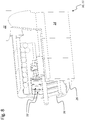
- FIGS. 1 to 25 For the same or equivalent elements of the invention are in the FIGS. 1 to 25 in each case identical reference numerals used. Furthermore, for the sake of clarity, only reference symbols are shown in the individual figures, which are required for the description of the respective figure. The illustrated embodiments are merely examples of how the device or method of the invention may be configured and are not an exhaustive limitation.
- FIGS. 1 and 2 each show perspective views of a first embodiment of a Verteilaggregates 10 according to the invention, which is provided for as uniform as possible, ideally for isolated delivery of granular material, in particular of seeds 12, fertilizer, etc.
- the distribution unit 10 may thus in the embodiment shown, a sowing unit 11 a distributor or sowing machine (not shown), in which normally a plurality of such sowing units 11 are arranged side by side for multi-row sowing.
- the distribution unit 10 or sowing unit 11 comprises an elongated housing 14 with a cylindrical inner surface 16 and an opening into the housing 14 inlet opening 18 for an air flow 20 with transported from this and transported into the housing 14 granular material or grains 12.
- the inlet opening 18 is Part of a connecting piece 22, which sits outside of the housing 14 and opens tangentially into this.
- a conveyor 24 mounted there, which can rotate concentrically there and the transport of the carried in the air flow 20 granular material or transported by this seed 12 is used.
- the air flow 20 and the rotating conveyor 24 promote the seeds 12 to an outlet opening 26 which connects approximately tangentially to the inner circumferential surface 16, as for example.
- the Fig. 4 ff clarify.
- the conveying device 24 has two paddle-like conveying elements 28 which strike along the inner lateral surface 16 and which are fastened opposite to a shaft 30 rotating concentrically in the housing 14.
- FIGS. 4 to 6 can recognize the paddle-like conveying elements 28 of the conveyor 24 for distribution and equalization of the crop flow of grains 12, although in the vicinity of the inlet opening 18 to first Can agglomerate 13 ( Fig. 5 . Fig. 6
- these are ideally lined up by the rotating movement of the conveying elements 28 in a manner such that the grains 12 are discharged through the outlet opening 26 individually and at constant intervals and in a constant dispensing direction ( Fig. 4 ), whereby the object of the present invention - the equalization of a good flow for the occasional delivery of grains - can be fulfilled as far as possible.
- Fig. 8 also discloses another option of the present invention.
- the inner circumferential surface 16 of the housing 14 may have a structuring 32 in the form of a continuous spiral, as in Fig. 3 and in Fig. 8 is recognizable.
- the spiral-shaped structuring 32 extends from a first end face 34, on which the connecting piece 22 is arranged, to the opposite end face 36, on which the outlet opening 26 is located.
- the spiral-like structure 32 is directed in the direction of rotation 38 of the conveyor 24 in the direction of the outlet opening 26 and opens there.
- the spiral-like structure 32 begins in the direction of rotation 38 of the conveyor 24 (see. Fig.
- the aforementioned spiral-like structure 32 may optionally have different pitch sections and be divided into a deceleration and separation winding.
- the delay thread provided with a smaller thread pitch is located near the inlet 18 and at the first end face 34, while the adjoining separating thread has a greater pitch in the direction of the outlet 26 and the second end face 36, so that the individual threads have approximately one width that corresponds to the diameter of the grains 12, so that they are guided in the threads.
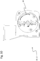
- FIGS. 9 to 13 let recognize how the uniformly rotating paddle-like conveying elements 28 of the conveyor 24 in connection with the running through the housing 14 uniform air flow 20 and possibly the (optional) spiral structure 32 of the inner circumferential surface 16 of the housing 14 a homogenization of the flow of material 40 (at Grains, seeds 12, etc.), which in the ideal case leads to an equidistant discharge at the outlet 26.
- the sowing unit according to the invention provides a uniform grain separation of high quality, if not too many grains 12 are transported in the air flow 20 and an excessively high speed applied to the rotating shaft 30.
- the presentation of the Fig. 10 shows the promotion of the grains 12 in the vicinity of the inlet opening 18, which is still partially disordered and has not yet led to an optimal distribution of all grains on the respective conveyor elements 28.
- Some of the grains 12 are still uncontrollably swirled around in the housing 14, wherein they are normally all on the inner circumferential surface 16 due to the centrifugal forces acting after passing through the inlet opening 18 and there perform a circular or spiral movement 48 in the direction of rotation 38 of the shaft 30.
- After multiple circular movements 48 and approaching the outlet opening 26 are normally no more grains 12 in the housing 14, which are not moved by the conveying elements 28 and abut there ( Fig. 12 ), so that they are discharged in an ideal tangential movement 50 as a separate material flow 40 through the outlet opening 26 down from the housing 14 ( Fig. 12 . Fig. 13 . Fig. 14 ).
- the individual arrangement of the grains 12 on the conveying elements 28 in the vicinity of the outlet opening 26 normally ensures that only one grain 12 at each passing of the end section of each conveying element 28 pointing in the direction of the second end face 36 onto a ramp 52 leading tangentially away from the inner circumferential surface 16 is derived to the outlet 26 ( Fig. 13 ).
- This ramp 52 can optionally be in Fig. 13 have shown contour and provide for a tangential grain movement 50 through the outlet opening 26.
- the ramp 52 can, however, in principle also be shaped differently and, for example, the in Fig. 14 shown curved profile 54 which deflects the grains 12 after the tangential detachment movement 50 in an axial movement 56 which is parallel to the longitudinal direction of the housing 14 extends.
- the design of the paddle-like conveying elements 28 ensures a sufficient free cross-section in the housing interior between the inlet port 18 and the Outlet opening 26, so that possibly a portion of the conveyed grains 12 past the conveying elements 28 between the central shaft 30 and the space between the shaft 30 and the conveying elements 28 arranged thereon be guided and leave the housing 14 through the outlet 26.
- the longitudinal sides 42 of the paddle-like conveying elements 28 extend parallel to the longitudinal direction of the housing 14 and the shaft 30 and have a width extending over several tracks or grooves of the spiral structure 32 extends. As the FIGS. 1 to 14 can be seen, the radially extending in the housing 14 narrow sides 44 of the conveying elements 28 are significantly shorter than the longitudinal sides 42 and measure less than one third of the inner diameter of the housing 14 in the illustrated embodiment.
- FIGS. 15 to 17 show a further embodiment of the Verteilaggregats 10 and the sowing unit 11, in which the conveying elements 28 of the rotating conveyor 24 have a slightly helical course in the direction parallel to the shaft 30, whereby the axial feed of the grains is given in the direction of the housing outlet 26.
- the surfaces of the paddle-like conveying elements 28 are curved in the direction of their longitudinal sides 42 in such a way that a helical contour results, in which an acute angle between the longitudinal extension direction of the housing and the surface of the conveying elements 28 is formed. This curved contour is particularly good in Fig. 17 recognizable.
- the thread-like structuring of the inner circumferential surface 16 can be dispensed with, since the helical contour of the conveying elements 28 ensures the axial grain feed.
- the slight axial feed can also be done by the air flow, and or the constant feeding of grains and the resulting slight self-displacement.
- combinations of helical conveying elements and thread-like structuring of different shape and depth are possible and useful.
- FIGS. 18a and 18b show various alternative embodiments of the conveying elements 28, which can be designed and dimensioned differently depending on the material to be separated. So that can be done in Fig. 18a
- the conveying element 28a shown on the left can be used particularly well for grain singulation in wheat, while, for example, the conveying element 28b depicted next to it can be used for oilseed rape.
- the further variants 28c, 28d and 28e may be suitable, for example, for soya or similarly shaped grains.
- variants of the conveying elements 28 are each provided with counterweights 58, so that, if necessary, can be dispensed with spring elements in the region of the pivotal mounting of the conveying elements 28 on the shaft 30.
- the molded counterweights 58 may rather provide for the radial alignment of the conveyor elements 28 with rapid rotation of the shaft 30, while they can easily avoid dips or resistance occurring.
- the conveying element 28f may be used for wheat, while the variant 28h may be suitable for rapeseed, for example.
- the variant 28i shows a helical course, as he already in the FIGS. 15 to 17 is shown.
- the rotating conveyor 24 may have two oppositely disposed conveying elements 28 which are anchored to the shaft 30 via a suitable attachment.
- the rotating conveyor 24 may have two oppositely disposed conveying elements 28 which are anchored to the shaft 30 via a suitable attachment.
- the conveying element 28 rotates ( Fig. 20 ) or in which three, four or more similar or differently shaped paddle-like conveying elements 28 are provided, which are each arranged uniformly spaced from each other on the central shaft 30.
- the Fig. 19 shows, for example, a variant with four at an angle of each 90 ° to each other standing conveying elements 28, which are arranged uniformly distributed on the shaft 30.
- the corresponding Fig. 18b can be configured, for example, can be used for the separation of rapeseed.
- the conveying element 28 shown there can also interact with semicircular disks 60 and 62, which prevent a direct flow through the small rapeseed grains in the housing 14. The very small rapeseed grains are thus delayed at the discs 60 and 62 designed as baffle plates and prevented from pushing uncontrollably to the exit 26.
- one of the semicircular and rotating with the shaft 30 discs 60 between the axially opening into the first end face 34 of the housing 14 inlet opening 18 and spaced from the end face 34 rotating conveyor element 28 may be arranged, while a second disc 62 in the vicinity of in the second end face 36 located outlet opening 26 may be arranged. While the first disc 60 covers a circle segment of about 180 ° in the embodiment shown, the second disc 62 can cover a circular segment of, for example, 270 °, so that the rapeseed grains contained in the housing 14 are effectively prevented from reaching the outlet prematurely, before they are delivered there in isolated form.
- the paddle-like conveying elements 28 can each be suspended resiliently on the central shaft 30, so that they can escape with increased resistance.
- the FIGS. 4 to 12 . Fig. 16 . 17 and 19 let corresponding pivot mechanisms 46 recognize that preferably allow a pivoting movement of the conveying elements 28 by a defined pivoting angle as soon as they are blocked by too many grains, by foreign matter such as stones, wood o. The like. This will prevent damage.
- the resilient suspension on the shaft 30 and counterweights 58 can provide for the alignment of the conveying elements 28 and for their evasive movements.
- each conveying element 28 may have a contouring, for example a kink or a concave curvature (cf. FIGS. 15-17 ). Such contouring can have a beneficial effect on the grain promotion.
- the paddle-like conveying elements 28 in the interest of a high distribution and separation quality should extend in width across a portion of the outlet opening 26, so that they are swept by the conveyor elements 28 with rotating conveyor 24 and the Verteilgut is ejected almost tangentially.
- the central shaft 30 of the conveyor 24 may, for example, be driven by an electric motor.
- the central shaft 30 of the conveyor 24 or the rotatable conveying elements 28 may also be driven via the air flow 20 conducted into the housing 14 through the inlet opening 18.
- FIGS. 22 to 25 show a further alternative embodiment of the Verteilaggregats 10, which is dispensed with a central shaft.
- the grains 12 are conveyed by a rotating housing portion 70 with transverse web 68 and a fixed turn 66 through the housing 14 in the axial direction to the grain exit or to the outlet opening 26.
- the windings 66 are fixedly connected to the stationary housing part 72 and / or to the stationary grain exit 26.
- the grains 12 are urged by the rotational centrifugal forces to the outside to the inner circumferential surface 16 of the rotating housing portion 66.
- the rotating crossbar 68 provides for advancing movement of the grains 12 in the direction of rotation along the circumference of the housing, while the stationary windings 66 of the non-rotating scroll 64 provide axial advancement in the direction from the inlet 18 to the outlet 26.
- the spacing of the spiral turns 66 from the inner circumferential surface 16 of the rotating housing section 70 must be at least slightly smaller than the smallest grain diameter, while the pitch of the turns 66 may be configured as needed. The pitch can be based on the grain size, the desired feed in connection with the rotational speed of the crosspiece 68 and other sheparameter.
Landscapes
- Life Sciences & Earth Sciences (AREA)
- Soil Sciences (AREA)
- Environmental Sciences (AREA)
- Sowing (AREA)
Claims (13)
- Groupe de distribution (10) de produits granuleux tels que graines (12), engrais ou équivalents, notamment groupe semoir (11) d'une machine de distribution ou semoir, comprenant un boîtier (14) de forme cylindrique doté d'au moins un orifice d'admission (18) pour le transport de produits granuleux ou de graines transportées (12) et d'un orifice d'échappement (26) ainsi que d'un dispositif de transport (24) rotatif doté d'au moins un élément de transport (28) rotatif, agencé ou s'étendant de manière approximativement axiale et radiale par rapport au boîtier (14) pour détecter les produits granuleux ou les graines (12), ceux-ci étant maintenus par des forces centrifuges contre une zone de gaine intérieure (16) du boîtier (14), s'y pressant et s'y mettant en position les uns contre les autres et formant une ligne ou s'alignant, ledit alignement faisant l'objet, au niveau de l'élément de transport (28) ou de la zone de gaine intérieure (16), d'une légère avancée dans un sens axial pour occuper de manière sure la position d'une graine (12) évacuée volontairement, de telle sorte qu'à chaque fois, une seule graine (12) longe la surface de la gaine (16) à la fin de l'alignement et dans une voie prédéterminée pour quitter l'orifice d'échappement (26) de manière approximativement tangentielle à la fin du processus de désassociation, caractérisé en ce que les graines (12) transportées ou emportées par l'élément de transport (28) ont au moins un espace libre unilatéral pour repousser l'excédent de graines (12) de telle sorte que puisse se former au niveau de l'élément de transport (28) un sens de graines approximativement linéaire.
- Groupe de distribution selon la revendication 1, dans lequel le boîtier (14) présente une surface de gaine intérieure (16) cylindrique ou se terminant unilatéralement en cône.
- Groupe de distribution selon la revendication 1 ou 2 auquel est appliqué un courant d'air (20) conduit au travers de l'orifice d'admission (18), ledit courant d'air (20) transportant les produits granuleux ou les graines (12), le flux d'air (20) par lequel les graines (12) sont amenées passant par le doseur (10) et continuant de porter les graines (12) remises dans ou après la remise.
- Groupe de distribution selon l'une quelconque des revendications 1 à 3, dans lequel chaque graine (12) transportée parcourt avant la remise de graine par l'échappement (26) un mouvement circulaire d'au moins 360°, ladite graine (12) étant maintenue par le au moins un élément de transport (28) sur une surface de gaine (16) approximativement cylindrique et faisant parallèlement l'objet d'une légère avancée axiale dans le sens de la remise de graine à l'échappement (26).
- Groupe de distribution selon l'une quelconque des revendications 1 à 4, dans lequel le dispositif de transport (24) présente au moins un élément de transport (28) en forme de rame qui passe le long de la surface de gaine intérieure (16).
- Groupe de distribution selon l'une quelconque des revendications 1 à 5, dans lequel l'avancée des graines (12) est donnée pour la dernière graine, au moins au niveau de l'orifice d'échappement (26), par un contour de guidage.
- Groupe de distribution selon l'une quelconque des revendications 1 à 6, dans lequel la surface de gaine intérieure (16) du boîtier (14) présente une structure (32) sous la forme d'une spirale ou glissière continue qui va d'un bout (34) au bout opposé (36) ou à une portion de cela, la structure en spirale (32) commençant, dans le sens de révolution (38) du dispositif de transport (24), au niveau de l'orifice d'admission (18).
- Groupe de distribution selon la revendication 7, dans lequel la structure en spirale (32) présente des tronçons ayant tous une inclinaison différente, l'inclinaison étant plus forte vers l'orifice d'échappement (26) qu'au niveau de l'orifice d'admission (18).
- Groupe de distribution selon la revendication 5 et l'une quelconque des revendications 6 à 8, dans lequel un côté longitudinal (42) de l'au moins un élément de transport (28) en forme de rame s'étend presque parallèlement au sens d'allongement longitudinal du boîtier (14), un côté étroit (44) de l'élément de transport (28) étant plus court que le côté longitudinal (42) et/ou l'au moins un élément de transport (28) en forme de rame allant dans sa largeur jusqu'au-dessus de l'orifice d'échappement de telle sorte que celui-ci est rasé au cours d'une rotation du dispositif de transport (24).
- Groupe de distribution selon la revendication 5 et l'une quelconque des revendications 6 à 9, dans lequel le dispositif de transport rotatif (24) présente deux, trois, quatre ou plusieurs éléments de transport (28) en forme de rame semblables ou de forme différente, lesdits éléments étant agencés sur un arbre central (30) chacun à équidistance l'un de l'autre.
- Groupe de distribution selon la revendication 5 et l'une quelconque des revendications 6 à 10, dans lequel l'élément de transport (28) en forme de rame ou les éléments de transport (28) en forme de rame sont chacun accrochés à l'arbre central de manière semi-rigide et/ou élastique de telle sorte qu'il(s) puisse(nt) se dérober en cas de résistance élevée.
- Groupe de distribution selon la revendication 5 et l'une quelconque des revendications 6 à 11, dans lequel l'élément de transport (28) en forme de rame ou les éléments de transport (28) en forme de rame du dispositif de transport (24) est/sont entraîné(s) par un moteur électrique.
- Groupe de distribution selon la revendication 5 et l'une quelconque des revendications 6 à 12, dans lequel l'élément de transport (28) en forme de rame ou les éléments de transport (28) en forme de rame du dispositif de transport (24) est/sont entraîné(s) par le courant d'air (20) conduit au travers de l'orifice d'admission (18) dans le boîtier (14).
Applications Claiming Priority (2)
| Application Number | Priority Date | Filing Date | Title |
|---|---|---|---|
| DE201210105081 DE102012105081A1 (de) | 2012-06-12 | 2012-06-12 | Verteilaggregat für körniges Gut, insbesondere Säaggregat |
| PCT/EP2013/061896 WO2013186161A1 (fr) | 2012-06-12 | 2013-06-10 | Ensemble de distribution de produit en grains, en particulier ensemble semoir |
Publications (2)
| Publication Number | Publication Date |
|---|---|
| EP2858472A1 EP2858472A1 (fr) | 2015-04-15 |
| EP2858472B1 true EP2858472B1 (fr) | 2017-11-22 |
Family
ID=48771399
Family Applications (1)
| Application Number | Title | Priority Date | Filing Date |
|---|---|---|---|
| EP13734975.9A Not-in-force EP2858472B1 (fr) | 2012-06-12 | 2013-06-10 | Dispositif d'épandage pour matériel granulaire, en particulier dispositif à semer |
Country Status (5)
| Country | Link |
|---|---|
| US (1) | US9591798B2 (fr) |
| EP (1) | EP2858472B1 (fr) |
| CA (1) | CA2876643C (fr) |
| DE (1) | DE102012105081A1 (fr) |
| WO (1) | WO2013186161A1 (fr) |
Families Citing this family (19)
| Publication number | Priority date | Publication date | Assignee | Title |
|---|---|---|---|---|
| DE102013215186A1 (de) | 2013-08-01 | 2015-02-05 | Horsch Maschinen Gmbh | Verfahren zur Dosierung von körnigem Gut und Dosiervorrichtung für körniges Gut |
| DE102013215182B4 (de) | 2013-08-01 | 2019-07-25 | Horsch Maschinen Gmbh | Verfahren zur Dosierung von körnigem Gut |
| DE102014110038A1 (de) | 2014-07-17 | 2016-01-21 | Amazonen-Werke H. Dreyer Gmbh & Co. Kg | Vorrichtung und Verfahren zur hochfrequenten Saatgutvereinzelung |
| DE102015001896A1 (de) | 2015-02-26 | 2016-09-01 | Gerald Funck | Vereinzelungsaggregat für körniges Gut |
| DE102015114362A1 (de) | 2015-08-28 | 2017-03-02 | Horsch Maschinen Gmbh | Säschar |
| CN118901349A (zh) * | 2016-07-29 | 2024-11-08 | 9754741加拿大有限公司 | 一种用于分离流中的颗粒的方法和装置 |
| DE102018120948A1 (de) * | 2018-08-28 | 2020-03-05 | Amazonen-Werke H. Dreyer Gmbh & Co. Kg | Verfahren zum Erfassen des Einflusses der Neigung eines landwirtschaftlichen Streugeräts auf die Streugutverteilung |
| US12419213B2 (en) | 2019-05-08 | 2025-09-23 | Precision Planting Llc | Aerodynamic and centrifugal seed orientation system for agricultural planters |
| AU2020268428B2 (en) | 2019-05-08 | 2025-08-14 | Precision Planting Llc | Seed orientation system for agricultural planters |
| DE102021106439A1 (de) | 2021-03-17 | 2022-09-22 | Amazonen-Werke H. Dreyer SE & Co. KG | Granulatportionierer für eine landwirtschaftliche Ausbringmaschine |
| WO2023007284A1 (fr) | 2021-07-28 | 2023-02-02 | Precision Planting Llc | Système d'orientation de graines aérodynamique et centrifuge pour planteuses agricoles |
| CA3227542A1 (fr) | 2021-10-11 | 2023-04-20 | Precision Planting Llc | Accelerateur de graines |
| WO2023062507A2 (fr) | 2021-10-11 | 2023-04-20 | Precision Planting Llc | Récepteur de semences et dispositif de contrainte de trajet pour un système d'orientation de semenses de planteuse agricole |
| GB202114710D0 (en) | 2021-10-14 | 2021-12-01 | Prec Planting Llc | Seed accelerator |
| CN113859546B (zh) * | 2021-10-21 | 2023-05-09 | 四川农业大学 | 一种多旋翼植保无人机的种肥两用撒播装置 |
| DE102021127899A1 (de) * | 2021-10-27 | 2023-04-27 | Amazonen-Werke H. Dreyer SE & Co. KG | Stromlos betreibbare Konditioniervorrichtung für ein pneumatisches Fördersystem einer landwirtschaftlichen Ausbringmaschine |
| CN118234373A (zh) | 2021-11-16 | 2024-06-21 | 精密种植有限责任公司 | 包括螺旋通道的种子递送装置和相关的行单元以及方法 |
| FR3134947B1 (fr) * | 2022-04-28 | 2024-05-31 | Kuhn Sas | Dispositif d’accélération d’au moins un élément granulaire de préférence une graine |
| CN115777300B (zh) * | 2022-11-06 | 2026-04-14 | 甘肃省农业科学院经济作物与啤酒原料研究所(甘肃省农业科学院中药材研究所) | 一种大麦育种试验用可均匀播种的大麦点播装置 |
Family Cites Families (20)
| Publication number | Priority date | Publication date | Assignee | Title |
|---|---|---|---|---|
| US3107779A (en) * | 1963-10-22 | Naxon | ||
| US767762A (en) * | 1903-05-12 | 1904-08-16 | Robert Hawthorn Mcclelland | Contrivance for regulating the distribution or feed of grain, &c. |
| US1553539A (en) * | 1919-10-08 | 1925-09-15 | Fuller Lehigh Co | Conveying pulverized material |
| DE1027924B (de) * | 1953-03-04 | 1958-04-10 | Hans Glas G M B H | Gleichstand-Saevorrichtung mit einem Scheibenschar, an dem ein Samenabstandsregler angeordnet ist, aus dem das Saatgut in eine am Schar angebrachte Leitrinne gelangt |
| US3796346A (en) | 1971-04-14 | 1974-03-12 | Ribouleau Ateliers | Distributing device for a sowing machine |
| US3741717A (en) * | 1971-12-27 | 1973-06-26 | L Triplett | Grain treating apparatuses and processes of operation thereof |
| DD242547A1 (de) | 1985-11-14 | 1987-02-04 | Mech Landwirtsch Forschzent | Vorrichtung zum vereinzeln und abgeben von koernigem gut |
| DD261948A1 (de) | 1987-07-14 | 1988-11-16 | Mech Landwirtsch Forschzent | Gutleiteinrichtung |
| DE3826321A1 (de) * | 1988-08-03 | 1990-02-08 | Deere & Co | Verteilvorrichtung fuer streugut |
| US5082141A (en) * | 1990-05-03 | 1992-01-21 | The United States Of America As Represented By The Secretary Of Agriculture | Device for singulating particles |
| DE4116724A1 (de) * | 1991-05-17 | 1992-11-19 | Harald Dipl Ing Hensel | Einzelkorndosiervorrichtung |
| FR2708173B1 (fr) | 1993-07-26 | 1995-09-29 | Ribouleau Ateliers | Boîtier de distribution pour semoir monograine mécanique. |
| DE19636787C1 (de) | 1996-09-11 | 1998-04-02 | Univ Hohenheim | Vergleichmäßigungsvorrichtung für die Dosierung von Granulat, insbesondere zur Verwendung bei einer Drillmaschine (Sämaschine) |
| US6062438A (en) * | 1998-04-20 | 2000-05-16 | Mars, Inc. | Apparatus for dispensing of bulk product |
| US6244388B1 (en) * | 1999-07-07 | 2001-06-12 | Sunny Die Casting, Inc. | Lube applicator for die cast machine plunger |
| US6112679A (en) * | 1999-07-19 | 2000-09-05 | Borstmayer; Darren | Liquid application unit for air seeders |
| DE10139947A1 (de) * | 2001-08-21 | 2003-03-06 | Kloeckner Haensel Proc Gmbh | Verfahren und Vorrichtung zur kontinuierlichen Förderung von Süßwarenmassen |
| CN100998281B (zh) * | 2006-12-23 | 2010-09-08 | 山西农业大学 | 多头异型螺旋槽小籽粒精少量排种装置 |
| US20140058559A1 (en) * | 2010-03-24 | 2014-02-27 | Michael N. Haynes | Systems, Devices, and/or Methods for Dispensing |
| US8671857B2 (en) * | 2011-03-10 | 2014-03-18 | Cnh Canada, Ltd. | Variable geometry meter roller |
-
2012
- 2012-06-12 DE DE201210105081 patent/DE102012105081A1/de not_active Withdrawn
-
2013
- 2013-06-10 EP EP13734975.9A patent/EP2858472B1/fr not_active Not-in-force
- 2013-06-10 WO PCT/EP2013/061896 patent/WO2013186161A1/fr not_active Ceased
- 2013-06-10 CA CA2876643A patent/CA2876643C/fr not_active Expired - Fee Related
- 2013-06-10 US US14/407,401 patent/US9591798B2/en not_active Expired - Fee Related
Also Published As
| Publication number | Publication date |
|---|---|
| WO2013186161A1 (fr) | 2013-12-19 |
| CA2876643A1 (fr) | 2013-12-19 |
| CA2876643C (fr) | 2017-08-15 |
| EP2858472A1 (fr) | 2015-04-15 |
| US20150122162A1 (en) | 2015-05-07 |
| US9591798B2 (en) | 2017-03-14 |
| DE102012105081A1 (de) | 2013-12-12 |
Similar Documents
| Publication | Publication Date | Title |
|---|---|---|
| WO2013186161A1 (fr) | Ensemble de distribution de produit en grains, en particulier ensemble semoir | |
| EP3412126B1 (fr) | Boîtier de distribution pour matériel granulaire, en particulier semoir | |
| EP2168416B1 (fr) | Dispositif de dosage monograin | |
| EP2832200B1 (fr) | Procédé et dispositif de dosage de matériel granulaire | |
| EP3127414B1 (fr) | Groupe de dosage pour semences | |
| EP3026998B1 (fr) | Procédé et dispositif de dosage de matériel granulaire | |
| EP3440908B1 (fr) | Dispositif de séparation pour matériau granulaire avec ensemble de conversion | |
| DE102015001896A1 (de) | Vereinzelungsaggregat für körniges Gut | |
| EP2910478A1 (fr) | Dispositif de dosage pour comprimés et procédé de dosage de comprimés | |
| EP2974584B1 (fr) | Dispositif et procédé de separation a hautes frequences de semences | |
| DE102014111777A1 (de) | Dosieraggregat für körniges Gut | |
| EP3135088B1 (fr) | Dispositif de dosage pour materiau granulaire comprenant un pre-dosage axial | |
| DE102015112813B4 (de) | Dosieraggregat und Verfahren zur Dosierung von körnigem Gut | |
| EP3340763B1 (fr) | Dispositif de dosage de matière granulaire avec une unité de pré-dosage | |
| EP3427563B1 (fr) | Dispositif de dosage avec prédosage et alimentation axiale | |
| DE102015010519A1 (de) | Auswurfbeschleunigungsvorrichtung für vereinzelte Körner körnigen Guts, Vereinzelungsaggregat mit diesem nachgeordneter Auswurfbeschleunigungsvorrichtung sowie hiermit ausgestattete Verteilvorrichtung | |
| WO2005124029A1 (fr) | Dispositif d'epandage de matiere granuleuse ou pulverulente | |
| DE102015114148A1 (de) | Dosiervorrichtung für granulares Material mit Schleuse | |
| DE1937524U (de) | Saevorrichtung zum aussaeen von behaartem baumwollsamen. |
Legal Events
| Date | Code | Title | Description |
|---|---|---|---|
| PUAI | Public reference made under article 153(3) epc to a published international application that has entered the european phase |
Free format text: ORIGINAL CODE: 0009012 |
|
| 17P | Request for examination filed |
Effective date: 20141208 |
|
| AK | Designated contracting states |
Kind code of ref document: A1 Designated state(s): AL AT BE BG CH CY CZ DE DK EE ES FI FR GB GR HR HU IE IS IT LI LT LU LV MC MK MT NL NO PL PT RO RS SE SI SK SM TR |
|
| AX | Request for extension of the european patent |
Extension state: BA ME |
|
| RIN1 | Information on inventor provided before grant (corrected) |
Inventor name: HORSCH, THOMAS |
|
| DAX | Request for extension of the european patent (deleted) | ||
| 17Q | First examination report despatched |
Effective date: 20170403 |
|
| GRAP | Despatch of communication of intention to grant a patent |
Free format text: ORIGINAL CODE: EPIDOSNIGR1 |
|
| INTG | Intention to grant announced |
Effective date: 20170623 |
|
| GRAS | Grant fee paid |
Free format text: ORIGINAL CODE: EPIDOSNIGR3 |
|
| GRAA | (expected) grant |
Free format text: ORIGINAL CODE: 0009210 |
|
| AK | Designated contracting states |
Kind code of ref document: B1 Designated state(s): AL AT BE BG CH CY CZ DE DK EE ES FI FR GB GR HR HU IE IS IT LI LT LU LV MC MK MT NL NO PL PT RO RS SE SI SK SM TR |
|
| REG | Reference to a national code |
Ref country code: GB Ref legal event code: FG4D Free format text: NOT ENGLISH |
|
| REG | Reference to a national code |
Ref country code: CH Ref legal event code: EP |
|
| REG | Reference to a national code |
Ref country code: IE Ref legal event code: FG4D Free format text: LANGUAGE OF EP DOCUMENT: GERMAN |
|
| REG | Reference to a national code |
Ref country code: AT Ref legal event code: REF Ref document number: 947496 Country of ref document: AT Kind code of ref document: T Effective date: 20171215 |
|
| REG | Reference to a national code |
Ref country code: DE Ref legal event code: R096 Ref document number: 502013008882 Country of ref document: DE |
|
| REG | Reference to a national code |
Ref country code: SE Ref legal event code: TRGR |
|
| REG | Reference to a national code |
Ref country code: NL Ref legal event code: MP Effective date: 20171122 |
|
| REG | Reference to a national code |
Ref country code: LT Ref legal event code: MG4D |
|
| PG25 | Lapsed in a contracting state [announced via postgrant information from national office to epo] |
Ref country code: ES Free format text: LAPSE BECAUSE OF FAILURE TO SUBMIT A TRANSLATION OF THE DESCRIPTION OR TO PAY THE FEE WITHIN THE PRESCRIBED TIME-LIMIT Effective date: 20171122 Ref country code: NO Free format text: LAPSE BECAUSE OF FAILURE TO SUBMIT A TRANSLATION OF THE DESCRIPTION OR TO PAY THE FEE WITHIN THE PRESCRIBED TIME-LIMIT Effective date: 20180222 Ref country code: NL Free format text: LAPSE BECAUSE OF FAILURE TO SUBMIT A TRANSLATION OF THE DESCRIPTION OR TO PAY THE FEE WITHIN THE PRESCRIBED TIME-LIMIT Effective date: 20171122 Ref country code: FI Free format text: LAPSE BECAUSE OF FAILURE TO SUBMIT A TRANSLATION OF THE DESCRIPTION OR TO PAY THE FEE WITHIN THE PRESCRIBED TIME-LIMIT Effective date: 20171122 Ref country code: LT Free format text: LAPSE BECAUSE OF FAILURE TO SUBMIT A TRANSLATION OF THE DESCRIPTION OR TO PAY THE FEE WITHIN THE PRESCRIBED TIME-LIMIT Effective date: 20171122 |
|
| PG25 | Lapsed in a contracting state [announced via postgrant information from national office to epo] |
Ref country code: HR Free format text: LAPSE BECAUSE OF FAILURE TO SUBMIT A TRANSLATION OF THE DESCRIPTION OR TO PAY THE FEE WITHIN THE PRESCRIBED TIME-LIMIT Effective date: 20171122 Ref country code: RS Free format text: LAPSE BECAUSE OF FAILURE TO SUBMIT A TRANSLATION OF THE DESCRIPTION OR TO PAY THE FEE WITHIN THE PRESCRIBED TIME-LIMIT Effective date: 20171122 Ref country code: GR Free format text: LAPSE BECAUSE OF FAILURE TO SUBMIT A TRANSLATION OF THE DESCRIPTION OR TO PAY THE FEE WITHIN THE PRESCRIBED TIME-LIMIT Effective date: 20180223 Ref country code: BG Free format text: LAPSE BECAUSE OF FAILURE TO SUBMIT A TRANSLATION OF THE DESCRIPTION OR TO PAY THE FEE WITHIN THE PRESCRIBED TIME-LIMIT Effective date: 20180222 Ref country code: LV Free format text: LAPSE BECAUSE OF FAILURE TO SUBMIT A TRANSLATION OF THE DESCRIPTION OR TO PAY THE FEE WITHIN THE PRESCRIBED TIME-LIMIT Effective date: 20171122 |
|
| REG | Reference to a national code |
Ref country code: FR Ref legal event code: PLFP Year of fee payment: 6 |
|
| PG25 | Lapsed in a contracting state [announced via postgrant information from national office to epo] |
Ref country code: DK Free format text: LAPSE BECAUSE OF FAILURE TO SUBMIT A TRANSLATION OF THE DESCRIPTION OR TO PAY THE FEE WITHIN THE PRESCRIBED TIME-LIMIT Effective date: 20171122 Ref country code: EE Free format text: LAPSE BECAUSE OF FAILURE TO SUBMIT A TRANSLATION OF THE DESCRIPTION OR TO PAY THE FEE WITHIN THE PRESCRIBED TIME-LIMIT Effective date: 20171122 Ref country code: CY Free format text: LAPSE BECAUSE OF FAILURE TO SUBMIT A TRANSLATION OF THE DESCRIPTION OR TO PAY THE FEE WITHIN THE PRESCRIBED TIME-LIMIT Effective date: 20171122 Ref country code: CZ Free format text: LAPSE BECAUSE OF FAILURE TO SUBMIT A TRANSLATION OF THE DESCRIPTION OR TO PAY THE FEE WITHIN THE PRESCRIBED TIME-LIMIT Effective date: 20171122 Ref country code: SK Free format text: LAPSE BECAUSE OF FAILURE TO SUBMIT A TRANSLATION OF THE DESCRIPTION OR TO PAY THE FEE WITHIN THE PRESCRIBED TIME-LIMIT Effective date: 20171122 |
|
| REG | Reference to a national code |
Ref country code: DE Ref legal event code: R097 Ref document number: 502013008882 Country of ref document: DE |
|
| PG25 | Lapsed in a contracting state [announced via postgrant information from national office to epo] |
Ref country code: PL Free format text: LAPSE BECAUSE OF FAILURE TO SUBMIT A TRANSLATION OF THE DESCRIPTION OR TO PAY THE FEE WITHIN THE PRESCRIBED TIME-LIMIT Effective date: 20171122 Ref country code: RO Free format text: LAPSE BECAUSE OF FAILURE TO SUBMIT A TRANSLATION OF THE DESCRIPTION OR TO PAY THE FEE WITHIN THE PRESCRIBED TIME-LIMIT Effective date: 20171122 Ref country code: SM Free format text: LAPSE BECAUSE OF FAILURE TO SUBMIT A TRANSLATION OF THE DESCRIPTION OR TO PAY THE FEE WITHIN THE PRESCRIBED TIME-LIMIT Effective date: 20171122 Ref country code: IT Free format text: LAPSE BECAUSE OF FAILURE TO SUBMIT A TRANSLATION OF THE DESCRIPTION OR TO PAY THE FEE WITHIN THE PRESCRIBED TIME-LIMIT Effective date: 20171122 |
|
| PG25 | Lapsed in a contracting state [announced via postgrant information from national office to epo] |
Ref country code: MT Free format text: LAPSE BECAUSE OF FAILURE TO SUBMIT A TRANSLATION OF THE DESCRIPTION OR TO PAY THE FEE WITHIN THE PRESCRIBED TIME-LIMIT Effective date: 20171122 |
|
| PLBE | No opposition filed within time limit |
Free format text: ORIGINAL CODE: 0009261 |
|
| STAA | Information on the status of an ep patent application or granted ep patent |
Free format text: STATUS: NO OPPOSITION FILED WITHIN TIME LIMIT |
|
| 26N | No opposition filed |
Effective date: 20180823 |
|
| PG25 | Lapsed in a contracting state [announced via postgrant information from national office to epo] |
Ref country code: SI Free format text: LAPSE BECAUSE OF FAILURE TO SUBMIT A TRANSLATION OF THE DESCRIPTION OR TO PAY THE FEE WITHIN THE PRESCRIBED TIME-LIMIT Effective date: 20171122 |
|
| REG | Reference to a national code |
Ref country code: CH Ref legal event code: PL |
|
| GBPC | Gb: european patent ceased through non-payment of renewal fee |
Effective date: 20180610 |
|
| REG | Reference to a national code |
Ref country code: BE Ref legal event code: MM Effective date: 20180630 |
|
| REG | Reference to a national code |
Ref country code: IE Ref legal event code: MM4A |
|
| PG25 | Lapsed in a contracting state [announced via postgrant information from national office to epo] |
Ref country code: LU Free format text: LAPSE BECAUSE OF NON-PAYMENT OF DUE FEES Effective date: 20180610 Ref country code: MC Free format text: LAPSE BECAUSE OF FAILURE TO SUBMIT A TRANSLATION OF THE DESCRIPTION OR TO PAY THE FEE WITHIN THE PRESCRIBED TIME-LIMIT Effective date: 20171122 |
|
| PG25 | Lapsed in a contracting state [announced via postgrant information from national office to epo] |
Ref country code: LI Free format text: LAPSE BECAUSE OF NON-PAYMENT OF DUE FEES Effective date: 20180630 Ref country code: IE Free format text: LAPSE BECAUSE OF NON-PAYMENT OF DUE FEES Effective date: 20180610 Ref country code: CH Free format text: LAPSE BECAUSE OF NON-PAYMENT OF DUE FEES Effective date: 20180630 Ref country code: GB Free format text: LAPSE BECAUSE OF NON-PAYMENT OF DUE FEES Effective date: 20180610 |
|
| PG25 | Lapsed in a contracting state [announced via postgrant information from national office to epo] |
Ref country code: BE Free format text: LAPSE BECAUSE OF NON-PAYMENT OF DUE FEES Effective date: 20180630 |
|
| PGFP | Annual fee paid to national office [announced via postgrant information from national office to epo] |
Ref country code: DE Payment date: 20190619 Year of fee payment: 7 |
|
| REG | Reference to a national code |
Ref country code: AT Ref legal event code: MM01 Ref document number: 947496 Country of ref document: AT Kind code of ref document: T Effective date: 20180610 |
|
| PGFP | Annual fee paid to national office [announced via postgrant information from national office to epo] |
Ref country code: SE Payment date: 20190619 Year of fee payment: 7 Ref country code: FR Payment date: 20190619 Year of fee payment: 7 |
|
| PG25 | Lapsed in a contracting state [announced via postgrant information from national office to epo] |
Ref country code: AT Free format text: LAPSE BECAUSE OF NON-PAYMENT OF DUE FEES Effective date: 20180610 |
|
| PG25 | Lapsed in a contracting state [announced via postgrant information from national office to epo] |
Ref country code: TR Free format text: LAPSE BECAUSE OF FAILURE TO SUBMIT A TRANSLATION OF THE DESCRIPTION OR TO PAY THE FEE WITHIN THE PRESCRIBED TIME-LIMIT Effective date: 20171122 |
|
| PG25 | Lapsed in a contracting state [announced via postgrant information from national office to epo] |
Ref country code: PT Free format text: LAPSE BECAUSE OF FAILURE TO SUBMIT A TRANSLATION OF THE DESCRIPTION OR TO PAY THE FEE WITHIN THE PRESCRIBED TIME-LIMIT Effective date: 20171122 |
|
| PG25 | Lapsed in a contracting state [announced via postgrant information from national office to epo] |
Ref country code: MK Free format text: LAPSE BECAUSE OF NON-PAYMENT OF DUE FEES Effective date: 20171122 Ref country code: HU Free format text: LAPSE BECAUSE OF FAILURE TO SUBMIT A TRANSLATION OF THE DESCRIPTION OR TO PAY THE FEE WITHIN THE PRESCRIBED TIME-LIMIT; INVALID AB INITIO Effective date: 20130610 |
|
| PG25 | Lapsed in a contracting state [announced via postgrant information from national office to epo] |
Ref country code: AL Free format text: LAPSE BECAUSE OF FAILURE TO SUBMIT A TRANSLATION OF THE DESCRIPTION OR TO PAY THE FEE WITHIN THE PRESCRIBED TIME-LIMIT Effective date: 20171122 Ref country code: IS Free format text: LAPSE BECAUSE OF FAILURE TO SUBMIT A TRANSLATION OF THE DESCRIPTION OR TO PAY THE FEE WITHIN THE PRESCRIBED TIME-LIMIT Effective date: 20180322 |
|
| REG | Reference to a national code |
Ref country code: DE Ref legal event code: R119 Ref document number: 502013008882 Country of ref document: DE |
|
| PG25 | Lapsed in a contracting state [announced via postgrant information from national office to epo] |
Ref country code: FR Free format text: LAPSE BECAUSE OF NON-PAYMENT OF DUE FEES Effective date: 20200630 |
|
| PG25 | Lapsed in a contracting state [announced via postgrant information from national office to epo] |
Ref country code: DE Free format text: LAPSE BECAUSE OF NON-PAYMENT OF DUE FEES Effective date: 20210101 Ref country code: SE Free format text: LAPSE BECAUSE OF NON-PAYMENT OF DUE FEES Effective date: 20200611 |
|
| REG | Reference to a national code |
Ref country code: SE Ref legal event code: EUG |