EP2858713B1 - Nouvelle soupape de tuyauterie et utilisations de celle-ci - Google Patents
Nouvelle soupape de tuyauterie et utilisations de celle-ci Download PDFInfo
- Publication number
- EP2858713B1 EP2858713B1 EP13804413.6A EP13804413A EP2858713B1 EP 2858713 B1 EP2858713 B1 EP 2858713B1 EP 13804413 A EP13804413 A EP 13804413A EP 2858713 B1 EP2858713 B1 EP 2858713B1
- Authority
- EP
- European Patent Office
- Prior art keywords
- valve
- tube
- tip
- stem
- valve stem
- Prior art date
- Legal status (The legal status is an assumption and is not a legal conclusion. Google has not performed a legal analysis and makes no representation as to the accuracy of the status listed.)
- Not-in-force
Links
- 210000002700 urine Anatomy 0.000 claims description 55
- 239000012530 fluid Substances 0.000 claims description 42
- 230000002485 urinary effect Effects 0.000 claims description 11
- 238000003780 insertion Methods 0.000 claims description 10
- 230000037431 insertion Effects 0.000 claims description 10
- 230000002209 hydrophobic effect Effects 0.000 claims description 8
- 230000000903 blocking effect Effects 0.000 claims description 5
- 230000000295 complement effect Effects 0.000 claims description 5
- 230000005499 meniscus Effects 0.000 claims description 4
- 239000007788 liquid Substances 0.000 description 8
- 239000000463 material Substances 0.000 description 3
- 238000000034 method Methods 0.000 description 3
- 239000000126 substance Substances 0.000 description 2
- 239000000853 adhesive Substances 0.000 description 1
- 230000001070 adhesive effect Effects 0.000 description 1
- 230000001580 bacterial effect Effects 0.000 description 1
- 239000008280 blood Substances 0.000 description 1
- 210000004369 blood Anatomy 0.000 description 1
- 231100000433 cytotoxic Toxicity 0.000 description 1
- 230000001472 cytotoxic effect Effects 0.000 description 1
- 230000005661 hydrophobic surface Effects 0.000 description 1
- 230000036445 liquid secretion Effects 0.000 description 1
- 238000004519 manufacturing process Methods 0.000 description 1
- 238000000465 moulding Methods 0.000 description 1
- 230000028327 secretion Effects 0.000 description 1
- 239000007787 solid Substances 0.000 description 1
- 230000001225 therapeutic effect Effects 0.000 description 1
- 231100000331 toxic Toxicity 0.000 description 1
- 230000002588 toxic effect Effects 0.000 description 1
- 208000019206 urinary tract infection Diseases 0.000 description 1
- -1 urine Substances 0.000 description 1
- XLYOFNOQVPJJNP-UHFFFAOYSA-N water Substances O XLYOFNOQVPJJNP-UHFFFAOYSA-N 0.000 description 1
- 238000003466 welding Methods 0.000 description 1
Images




Classifications
-
- A—HUMAN NECESSITIES
- A61—MEDICAL OR VETERINARY SCIENCE; HYGIENE
- A61F—FILTERS IMPLANTABLE INTO BLOOD VESSELS; PROSTHESES; DEVICES PROVIDING PATENCY TO, OR PREVENTING COLLAPSING OF, TUBULAR STRUCTURES OF THE BODY, e.g. STENTS; ORTHOPAEDIC, NURSING OR CONTRACEPTIVE DEVICES; FOMENTATION; TREATMENT OR PROTECTION OF EYES OR EARS; BANDAGES, DRESSINGS OR ABSORBENT PADS; FIRST-AID KITS
- A61F5/00—Orthopaedic methods or devices for non-surgical treatment of bones or joints; Nursing devices ; Anti-rape devices
- A61F5/44—Devices worn by the patient for reception of urine, faeces, catamenial or other discharge; Colostomy devices
- A61F5/4404—Details or parts
- A61F5/4405—Valves or valve arrangements specially adapted therefor ; Fluid inlets or outlets
-
- A—HUMAN NECESSITIES
- A61—MEDICAL OR VETERINARY SCIENCE; HYGIENE
- A61F—FILTERS IMPLANTABLE INTO BLOOD VESSELS; PROSTHESES; DEVICES PROVIDING PATENCY TO, OR PREVENTING COLLAPSING OF, TUBULAR STRUCTURES OF THE BODY, e.g. STENTS; ORTHOPAEDIC, NURSING OR CONTRACEPTIVE DEVICES; FOMENTATION; TREATMENT OR PROTECTION OF EYES OR EARS; BANDAGES, DRESSINGS OR ABSORBENT PADS; FIRST-AID KITS
- A61F5/00—Orthopaedic methods or devices for non-surgical treatment of bones or joints; Nursing devices ; Anti-rape devices
- A61F5/44—Devices worn by the patient for reception of urine, faeces, catamenial or other discharge; Colostomy devices
- A61F5/451—Genital or anal receptacles
-
- A—HUMAN NECESSITIES
- A61—MEDICAL OR VETERINARY SCIENCE; HYGIENE
- A61M—DEVICES FOR INTRODUCING MEDIA INTO, OR ONTO, THE BODY; DEVICES FOR TRANSDUCING BODY MEDIA OR FOR TAKING MEDIA FROM THE BODY; DEVICES FOR PRODUCING OR ENDING SLEEP OR STUPOR
- A61M39/00—Tubes, tube connectors, tube couplings, valves, access sites or the like, specially adapted for medical use
- A61M39/10—Tube connectors; Tube couplings
-
- A—HUMAN NECESSITIES
- A61—MEDICAL OR VETERINARY SCIENCE; HYGIENE
- A61M—DEVICES FOR INTRODUCING MEDIA INTO, OR ONTO, THE BODY; DEVICES FOR TRANSDUCING BODY MEDIA OR FOR TAKING MEDIA FROM THE BODY; DEVICES FOR PRODUCING OR ENDING SLEEP OR STUPOR
- A61M39/00—Tubes, tube connectors, tube couplings, valves, access sites or the like, specially adapted for medical use
- A61M39/10—Tube connectors; Tube couplings
- A61M39/12—Tube connectors; Tube couplings for joining a flexible tube to a rigid attachment
-
- F—MECHANICAL ENGINEERING; LIGHTING; HEATING; WEAPONS; BLASTING
- F16—ENGINEERING ELEMENTS AND UNITS; GENERAL MEASURES FOR PRODUCING AND MAINTAINING EFFECTIVE FUNCTIONING OF MACHINES OR INSTALLATIONS; THERMAL INSULATION IN GENERAL
- F16L—PIPES; JOINTS OR FITTINGS FOR PIPES; SUPPORTS FOR PIPES, CABLES OR PROTECTIVE TUBING; MEANS FOR THERMAL INSULATION IN GENERAL
- F16L37/00—Couplings of the quick-acting type
- F16L37/28—Couplings of the quick-acting type with fluid cut-off means
- F16L37/38—Couplings of the quick-acting type with fluid cut-off means with fluid cut-off means in only one of two pipe-end fittings
- F16L37/40—Couplings of the quick-acting type with fluid cut-off means with fluid cut-off means in only one of two pipe-end fittings with a lift valve being opened automatically when the coupling is applied
-
- A—HUMAN NECESSITIES
- A61—MEDICAL OR VETERINARY SCIENCE; HYGIENE
- A61J—CONTAINERS SPECIALLY ADAPTED FOR MEDICAL OR PHARMACEUTICAL PURPOSES; DEVICES OR METHODS SPECIALLY ADAPTED FOR BRINGING PHARMACEUTICAL PRODUCTS INTO PARTICULAR PHYSICAL OR ADMINISTERING FORMS; DEVICES FOR ADMINISTERING FOOD OR MEDICINES ORALLY; BABY COMFORTERS; DEVICES FOR RECEIVING SPITTLE
- A61J1/00—Containers specially adapted for medical or pharmaceutical purposes
- A61J1/05—Containers specially adapted for medical or pharmaceutical purposes for collecting, storing or administering blood, plasma or medical fluids ; Infusion or perfusion containers
- A61J1/10—Bag-type containers
-
- A—HUMAN NECESSITIES
- A61—MEDICAL OR VETERINARY SCIENCE; HYGIENE
- A61J—CONTAINERS SPECIALLY ADAPTED FOR MEDICAL OR PHARMACEUTICAL PURPOSES; DEVICES OR METHODS SPECIALLY ADAPTED FOR BRINGING PHARMACEUTICAL PRODUCTS INTO PARTICULAR PHYSICAL OR ADMINISTERING FORMS; DEVICES FOR ADMINISTERING FOOD OR MEDICINES ORALLY; BABY COMFORTERS; DEVICES FOR RECEIVING SPITTLE
- A61J1/00—Containers specially adapted for medical or pharmaceutical purposes
- A61J1/14—Details; Accessories therefor
- A61J1/1412—Containers with closing means, e.g. caps
-
- A—HUMAN NECESSITIES
- A61—MEDICAL OR VETERINARY SCIENCE; HYGIENE
- A61M—DEVICES FOR INTRODUCING MEDIA INTO, OR ONTO, THE BODY; DEVICES FOR TRANSDUCING BODY MEDIA OR FOR TAKING MEDIA FROM THE BODY; DEVICES FOR PRODUCING OR ENDING SLEEP OR STUPOR
- A61M39/00—Tubes, tube connectors, tube couplings, valves, access sites or the like, specially adapted for medical use
- A61M39/22—Valves or arrangement of valves
- A61M39/26—Valves closing automatically on disconnecting the line and opening on reconnection thereof
-
- A—HUMAN NECESSITIES
- A61—MEDICAL OR VETERINARY SCIENCE; HYGIENE
- A61M—DEVICES FOR INTRODUCING MEDIA INTO, OR ONTO, THE BODY; DEVICES FOR TRANSDUCING BODY MEDIA OR FOR TAKING MEDIA FROM THE BODY; DEVICES FOR PRODUCING OR ENDING SLEEP OR STUPOR
- A61M5/00—Devices for bringing media into the body in a subcutaneous, intra-vascular or intramuscular way; Accessories therefor, e.g. filling or cleaning devices, arm-rests
- A61M5/14—Infusion devices, e.g. infusing by gravity; Blood infusion; Accessories therefor
- A61M5/162—Needle sets, i.e. connections by puncture between reservoir and tube ; Connections between reservoir and tube
Definitions
- the present invention relates generally to a novel tubing valve that may be used in low and medium pressure applications in general, and in particular to a novel medical valve that may be used for example in systems for removal of urine from catheterized patients to thereby allow avoiding any contact with the patient's urine.
- the present invention in at least some embodiments is directed to a novel tubing valve which is particularly applicable to medical uses.
- the medical tubing valve may optionally be used for urine collection systems, for example to permit a collecting bag that is in use to be removed and to be replaced by a fresh bag, while preventing any contact between the medical team performing the replacement and the liquids in the collecting bag, and therefore keeping the near surrounding and medical staff clean.
- hygienic systems and methods for collecting urine from a patient wherein the systems comprise a novel medical tubing valve that functionally prevents direct contact between the medical team and the urine.
- the valve may also optionally be used for non-medical applications, for example in situations where it is desirable to prevent contact with undesirable substances upon changing receptacles for such substances that are connected to tubing. These applications might include drawing off samples of corrosive fluid from a flow, checking fluid concentrations, checking fluid residue, or draining fluid residues in general.
- a tubing valve comprising: a valve body; a valve stem adapted to be inserted into the valve body where the valve stem has an inlet port; and a valve tip adapted to be inserted and fixed into the valve stem after a first end of the valve tip is positioned inside the valve stem wherein a second end of the valve tip is adapted to hold a tube, wherein the tubing valve is adapted to open upon attaching the tube to the valve tip, causing the valve stem to move away from the valve body and to permit fluid access to the inlet port, and is adapted to close upon removing the tube from the valve tip, causing the valve stem to move toward the valve body and to block fluid access to the inlet port.
- valve body further comprises a central bore, wherein the valve stem comprises a first portion having a greater area and a second portion having a smaller area, wherein a portion of the central bore is narrower than a second portion of the central bore, the narrower portion receiving the second portion of the valve stem and the second portion of the central bore receiving the first portion of the valve stem having the greater area.
- the first end of the valve tip contacts the second portion of the valve stem and causes the valve stem having the inlet port to move away from the valve body to open the valve.
- the second end of the valve tip is adapted to be inserted into the tube and is adapted to cause the first end of the valve tip to contact the second portion of the valve stem.
- the narrower portion of the central bore is adapted to be inserted into the tube with the second end of the valve tip, thereby preventing the valve from closing when the tube is attached to the valve.
- the second end of the valve tip is adapted to move away from the valve body upon removal of the tube and hence to cause the first end of the valve tip to cease to contact the second portion of the valve stem having the inlet port, thereby closing the valve.
- valve stem and the central bore of the valve body each comprise complementary conical structures, such that when the tubing valve is closed, the conical structure of the valve stem having the inlet port is larger than the conical structure of the central bore, thereby blocking the inlet port.
- valve is adapted to be used in low and medium pressure applications.
- valve further comprises a medical tube attached to the valve.
- valve is positioned in a urinary catheter system, and wherein the medical tube is a urine collecting bag tube.
- an urinary catheter system comprising: a catheter for insertion to the patient, a urine collection bag, a urine collection bag tube, a tubing valve according to the first aspect of the present invention, and a tube having an inner diameter from four millimeters to six millimeters, the tube having an inner surface which is hydrophobic at least along a first segment thereof and being adapted to provide a continuously negative fluid pressure therein, the tube being connected to the catheter at one end of the tube, and the tube being connected to one end of the tubing valve at an opposite end of the tube, and the valve being connected to the urine collection bag tube at an opposite end of the valve such that the tube conveys a column of fluid held by a meniscus of the column of fluid from the catheter to the collection bag without interruption; wherein the valve is adapted to be open upon connecting the urine collection bag tube and the valve is adapted to be closed upon disconnecting the urine collection bag tube.
- system further comprises a drop counter, wherein at the opposite end of the tube, the tube is connected to the drop counter and the tubing valve is connected to the drop counter.
- the tubing valve comprises: a valve body adapted for connecting to the drop counter; a valve stem adapted to be inserted into the valve body where the valve stem has an inlet port; and a valve tip adapted to be inserted and fixed into the valve stem after a first end of the valve tip is positioned inside the valve body, wherein a second end of the valve tip is adapted to hold the urine collection bag tube, wherein the tubing valve is adapted to open upon attaching the urine collection bag tube to the valve tip, causing the valve stem and the inlet port to move away from the valve body and to permit fluid access to the inlet port, and is adapted to close upon removing the tube from the valve tip, causing the valve stem and the inlet port to move toward the valve body and to block fluid access to the inlet port.
- valve body further comprises a central bore, wherein the valve stem comprises a first portion having a greater area and a second portion having a smaller area, wherein a portion of the central bore is narrower than a second portion of the central bore, the narrower portion receiving the second portion of the valve stem and the second portion of the central bore receiving the first portion of the valve stem having the greater area.
- the first end of the valve tip is adapted to contact the second portion of the valve stem and is adapted to cause the valve stem having the inlet port to move away from the valve body to open the valve.
- the second end of the valve tip is adapted to be inserted into the urine collection bag tube and is adapted to cause the first end of the valve tip to contact the second portion of the valve stem.
- the narrower portion of the central bore is adapted to be inserted into the urine collection bag tube with the second end of the valve tip, thereby preventing the valve from closing when the urine collection bag tube is attached to the valve.
- the second end of the valve tip is adapted to move away from the valve body upon removal of the urine collection bag tube and hence to cause the first end of the valve tip to cease to contact the second portion of the valve stem having the inlet port, thereby closing the valve.
- valve stem and the central bore of the valve body each comprise complementary conical structures, such that when the tubing valve is closed, the conical structure of the valve stem having the inlet port is larger than the conical structure of the central bore, thereby blocking the inlet port.
- a method for enhanced continuous flow of urine in a catheterized patient comprising: providing an arrangement comprising a hydrophobic tube having an inner diameter of from four to six millimeters, the tube having an inner surface which is hydrophobic at least along a first segment thereof and being arranged to provide a continuously negative fluid pressure therein; attaching the hydrophobic tube to the urinary catheter unit; attaching the hydrophobic tube to a drop counter inlet; attaching a drop counter outlet to a tubing valve, wherein the valve comprises: a valve body; a valve stem adapted to be inserted into the valve body where the valve stem has an inlet port; and a valve tip adapted to be inserted and fixed into the valve stem after a first end of the valve tip is positioned inside the valve body, wherein the hydrophobic tube is attached to a first end of the valve tip; attaching a second end of the valve tip to a urine collection bag tube, thereby causing the valve to open; connecting the collection bag tube to a urine collection bag, the catheter unit being
- valve body further comprises a central bore, wherein the valve stem comprises a first portion having a greater area and a second portion having a smaller area, wherein a portion of the central bore is narrower than a second portion of the central bore, the narrower portion receiving the second portion of the valve stem and the second portion of the central bore receiving the first portion of the valve stem having the greater area.
- the first end of the valve tip contacts the second portion of the valve stem and causes the valve stem having the inlet port to move away from the valve body to open the valve.
- the second end of the valve tip is adapted to be inserted into the urine collection bag tube and is adapted to cause the first end of the valve tip to contact the second portion of the valve stem.
- the narrower portion of the central bore is adapted to be inserted into the urine collection bag tube with the second end of the valve tip, thereby preventing the valve from closing when the urine collection bag tube is attached to the valve.
- the second end of the valve tip is adapted to move away from the valve body upon removal of the urine collection bag tube and hence to cause the first end of the valve tip to cease to contact the second portion of the valve stem having the inlet port, thereby closing the valve.
- valve stem and the central bore of the valve body each comprise complementary conical structures, such that when the tubing valve is closed, the conical structure of the valve stem having the inlet port is larger than the conical structure of the central bore, thereby blocking the inlet port.
- an urinary catheter system comprising: a catheter for insertion to the patient, a catheter tube, a tubing valve, and a urine collection bag having a urine collection bag tube, the catheter tube being connected to the catheter at one end of the tube, and the tube being connected to one end of the valve at an opposite end of the tube, and the valve being connected to the urine collection bag tube at an opposite end of the valve, wherein the tubing valve is adapted to permit fluid flow when the urine collection bag tube is connected and prevent fluid flow when the urine collection bag tube is removed.
- the valve comprises: a valve body; a valve stem adapted to be inserted into the valve body where the valve stem has an inlet port; and a valve tip adapted to be inserted and fixed into the valve stem after a first end of the valve tip is positioned inside the valve body, wherein a second end of the valve tip is adapted to hold the urine collection bag tube.
- valve body further comprises a central bore, wherein the valve stem comprises a first portion having a greater area and a second portion having a smaller area, wherein a portion of the central bore is narrower than a second portion of the central bore, the narrower portion receiving the second portion of the valve stem and the second portion of the central bore receiving the first portion of the valve stem having the greater area.
- the first end of the valve tip contacts the second portion of the valve stem and causes the valve stem having inlet port to move away from the valve body to open the valve.
- the second end of the valve tip is adapted to be inserted into the urine collection bag tube and is adapted to cause the first end of the valve tip to contact the second portion of the valve stem.
- the narrower portion of the central bore is adapted to be inserted into the urine collection bag tube with the second end of the valve tip, thereby preventing the valve from closing when the urine collection bag tube is attached to the valve.
- the second end of the valve tip is adapted to move away from the valve body upon removal of the urine collection bag tube and hence to cause the first end of the valve tip to cease to contact the second portion of the valve stem having the inlet port, thereby closing the valve.
- valve stem and the central bore of the valve body each comprise complementary conical structures, such that when the tubing valve is closed, the conical structure of the valve stem having the inlet port is larger than the conical structure of the central bore, thereby blocking the inlet port.
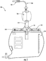
- FIG. 1 and 2 schematically illustrate a urinary catheterization kit 100 comprising a catheter 102, a catheterization tube 104, a receiving reservoir 108, drop chamber 110, the valve 120 of the present invention, a urine collecting bag attachment tube 130, and a means for attachment 132 of the kit 100 to a urine collection bag 134, in accordance with variations of the present invention.
- Valve 120 comprises valve body 122, valve stem 124 and valve tip 126 as will be described in more detail below.
- valve 120 is positioned between drop chamber 110 and attachment tube 130.
- the inlet of valve body 122 is preferably sized to allow the outlet of drop chamber 110 to be attached and held in place without the need for any retaining mechanism.
- the valve 120 will remain attached under medium or high pressures not exceeding approximately 400 kPa (4 bar).
- valve 120 is preferably sized to allow attachment tube 130 to be attached and held in place without the need for any retaining mechanism.
- valve 120 When used in a urinary catheterization system the closing as well as the opening of valve 120 is very intuitive and allows the removal and replacement of collection bag 134, while preventing any contact between the medical team performing the replacement and the liquids in the collection bag, therefore keeping the near surrounding and medical staff clean.
- valve 120 When collection bag 134 with attachment tube 130 is detached or otherwise removed from valve 120, valve 120 is pulled close preventing the flow of liquid, and when collection bag 134 with tube 130 is pushed onto or otherwise connected to valve 120, valve 120 is pushed open allowing the flow of liquid. This mechanism will be described in more detail below.
- the valve may be used in urinary catheter arrangements as illustrated in detail in U.S. Pat Application No. 2010/0286667 (hereinafter: "667').
- the arrangement shown in Figure 1 is similar to the arrangements of the above reference and may optionally have the same or similar parameters as described below.
- the arrangement illustrated in 667' is arranged for enhanced continuous flow of urine in a catheterized patient and for preventing urinary tract infections in the patient.
- the arrangement generally comprises a catheter tube with a hydrophobic inner surface that is preferably polished, having an inner diameter of four to six millimeters, the tube being arranged to provide a continuously negative fluid pressure of less than 4903 Pa (50 cm equivalent of water) therein as a result of a meniscus forming at the beginning of a flow of urine from the bladder of the patient as a result of the narrowness of the tube and the repulsion of the urine from the hydrophobic surfaces of the tube, whereby during operation, the tube is always full of urine.
- 4903 Pa 50 cm equivalent of water
- valve 120 provides a solution to this problem and to allow replacement of a urine bag, such as urine collection bag 134, or any other collected secreted fluids in a clean and sterile manner.
- a urine bag such as urine collection bag 134
- valve 120 closes and no flow through valve 120 is possible.
- valve 120 prevents direct human contact with the urine or with other biohazardous materials as there is no need to touch any other part other than attachment tube 130 of collection bag 134 when replacing collection bag 134.
- Valve 300 generally comprises three components: a valve stem 310, a valve body 330, and a valve tip 340.
- Valve stem 310 preferably comprises an elongated hollow cylindrical portion; valve stem cylinder 312 attached to wider solid valve stem top 314.
- Valve stem cylinder 312 preferably has a conical surface 316.
- Valve stem 310 also preferably includes one or more stem inlet ports 318 that are situated below valve stem top 314, and a valve stem outlet 320.
- Conical surface 316 may optionally be a frustoconical surface.
- Valve body 330 comprises a valve inlet chamber 332, and a central bore 334.
- Inlet chamber 332 is preferably shaped and sized so that its outer dimensions are slightly smaller than the inner dimensions of a drop chamber in a urinary catheter kit such as the drop chamber 110 described in Figure 1 above or optionally any other tubing or attachment mechanism in applications where the valve 300 is employed in order to allow the tight attachment of valve body 330 to said drop chamber, tubing or attachment. This attachment is further described below.
- Central bore 334 is preferably cylindrical and hollow with an inner diameter slightly wider than the outer diameter of valve stem cylinder 312.
- the inner surface 336 of central bore 334 preferably has a conical or frustoconical form, preferably shaped to match the conical or frustoconical surface 316 on the outer surface of stem cylinder 312. These dimensions preferably allow the insertion of valve stem 310 into valve body 330 so that the conical surface 316 of stem cylinder 312 fits snugly against the conical inner surface 336 of central bore 334.
- Valve tip 340 preferably comprises a tube attachment part 342, a stem insertion part 344 and valve outlet port 346.
- Tube attachment part 342 is preferably conically shaped and sized so that its outer dimensions are the same or slightly wider than the inner dimensions of an attachment tube in a urinary catheter kit such as the attachment tube 130 described above or optionally any other tubing or attachment mechanism in applications where the valve 300 is employed in order to allow the tight attachment of the valve to said attachment tube, or other tubing or attachment.
- Stem insertion part 344 is preferably sized to so that its outer diameter is slightly smaller than valve stem outlet 310. This enables stem insertion 344 of valve tip 340 to be attached to stem outlet 310 optionally using adhesive or ultrasonic welding so as to permanently fix it after insertion.
- valve 300 in a closed and open position respectively, in accordance with variations of the invention.
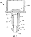
- Figure 4 is a schematic cross section view of valve 300 of Figure 3 in a closed position, in accordance with variations of the present invention.
- the assembled valve preferably includes valve stem 310 inserted into valve body 330.
- Valve stem outlet 310 is attached to stem insertion 344 of valve tip 340.
- the assembled valve stem and valve tip can move up and down within the valve body.
- valve 300 When valve 300 is in a closed position, inlet port 318 is sealed against the inner surface 336 of central bore 334. Conical surface 316 of valve stem 310 is pressed against conical inner surface 336 of central bore 334 creating a light interference fit that will hold the valve closed. The conical shape of the interference fit allows the fit to be broken with relative ease.
- a gap 410 exists between valve body 330 and the tube insertion part 342 of valve tip 340.
- FIG. 5 is a schematic cross section view showing the valve 300 of Figure 3 in an open position, in accordance with variations of the present invention.
- valve 300 When valve 300 is in an open position, assembled valve stem 310 and valve tip 340 together move upward closing gap 410.
- Inlet port 318 is not blocked by the inner surface 336 of central bore 334.
- valve inlet chamber 332 is preferably attached to a source of fluid, which may optionally include the drop chamber 110 of catheter assembly 100 of Figure 1 or any other source of fluid depending on the application in which the valve is used.
- the attachment is made by sliding the outlet attachment 610 of the fluid source over the outside surface of the valve inlet chamber 332.
- the size and shape of inlet chamber 332 preferably matches that of the outlet attachment 610 in use.
- the outlet of valve 300 is preferably attached to the destination of the fluid flow which may optionally include the attachment tube 130 of catheter assembly 100 of Figure 1 or any other fluid destination depending on the application in which the valve is used.
- the attachment is made by sliding the attachment tube 620 of the fluid destination over the outside surface of the tube attachment port 342 and the central bore 334.
- the size and shape of attachment port 342 preferably matches that of the tube attachment 620 in use.
- the conical shape of attachment port 342 preferably eases the process of deforming tube 620 when sliding it onto the valve.
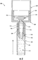
- Figure 6 is a schematic cross section view showing the valve 300 of Figure 3 in an open position, in accordance with variations of the present invention.
- fluid 510 that has accumulated in valve inlet chamber 332 of valve body 330 flows through inlet port 318 and stem cylinder 312 of valve stem 310 before exiting the valve through outlet port 346 of valve tip 340.
- Tube 620 holds valve 300 in an open position by gripping the outer surface of central bore 334 and the outer surface of valve tip 340.
- FIG. 7 is a schematic cross section view showing the valve 300 of Figure 3 pulled into a closed position, in accordance with variations of the present invention.
- valve tip 340 is pulled downward due to the friction against tube attachment part 342.
- Valve stem 310 which is attached to valve tip 340 is also pulled down causing stem inlet ports 318 to be sealed against the inner surface 336 of central bore 334 and preventing the further flow of fluids 510 accumulated in inlet chamber 332 through the valve.
- Conical surface 316 of valve stem 310 is pressed against conical inner surface 336 of central bore 334 creating a light interference fit that holds the valve closed.
- FIG 8 is a schematic cross section view showing the valve 300 of Figure 3 pushed into an open position, in accordance with variations of the present invention.
- an attachment tube 620 is forced onto the valve 300 by pushing it over the conical surface of attachment part 342 of valve tip 340, the valve tip is pushed upward.
- Valve stem 310 which is attached to valve tip 340 is also pushed upward breaking the light interference fit between conical surface 316 of valve stem 310 and conical inner surface 336 of central bore 334.
- Stem inlet ports 318 are pushed out of the central bore 334 allowing fluid 510 that has accumulated in inlet chamber 332 to once more enter inlet ports 318 and stem cylinder of valve stem 310, before exiting the valve through outlet port 346 of valve tip 340.
- Tube 620 holds valve 300 in an open position by gripping the outer surface of central bore 334 and the outer surface of valve tip 340.
- the valve of the present invention aims to allow replacement of a urine bag or any other collected secreted fluids in a clean and sterile manner.
- the valve closes and no flow through the valve is possible.
- the valve prevents direct human contact with urine or with other biohazardous materials as there is no need to touch any other part other than the outer tube 620 of the collecting bag when replacing it.
Landscapes
- Health & Medical Sciences (AREA)
- Heart & Thoracic Surgery (AREA)
- Engineering & Computer Science (AREA)
- Public Health (AREA)
- General Health & Medical Sciences (AREA)
- Biomedical Technology (AREA)
- Veterinary Medicine (AREA)
- Life Sciences & Earth Sciences (AREA)
- Animal Behavior & Ethology (AREA)
- Orthopedic Medicine & Surgery (AREA)
- Vascular Medicine (AREA)
- Epidemiology (AREA)
- Nursing (AREA)
- Hematology (AREA)
- Pulmonology (AREA)
- Anesthesiology (AREA)
- General Engineering & Computer Science (AREA)
- Mechanical Engineering (AREA)
- External Artificial Organs (AREA)
- Infusion, Injection, And Reservoir Apparatuses (AREA)
- Lift Valve (AREA)
- Sink And Installation For Waste Water (AREA)
- Mechanically-Actuated Valves (AREA)
Claims (10)
- Soupape de tubulure (120, 300), comprenant : un corps de soupape (122, 330) ; une tige de soupape (124, 310) configurée pour être insérée dans ledit corps de soupape là où ladite tige de soupape comporte un orifice d'admission ; et un bout de soupape (126, 340) dans laquelle une seconde extrémité (342) dudit bout de soupape est configurée pour contenir un tube (620), dans laquelle ladite soupape de tubulure est configurée pour s'ouvrir lors de la fixation dudit tube audit bout de soupape, amenant ladite tige de soupape à s'éloigner dudit corps de soupape et à permettre un accès de fluide audit orifice d'admission, et configurée pour se fermer lors du retrait dudit tube dudit bout de soupape, amenant ladite tige de soupape à se déplacer vers ledit corps de soupape et à bloquer l'accès de fluide audit orifice d'admission, et caractérisée en ce que le bout de soupape (126, 340) est configuré pour être inséré et assujetti dans ladite tige de soupape après le positionnement d'une première extrémité (344) dudit bout de soupape à l'intérieur de ladite tige de soupape (124, 310).
- Soupape selon la revendication 1, dans laquelle ledit corps de soupape (330) comprend en outre un alésage central (334), dans laquelle ladite tige de soupape (310) comprend une première portion (314) ayant une superficie plus grande et une seconde portion (312) ayant une superficie plus petite, dans laquelle une portion dudit alésage central est plus étroite qu'une seconde portion dudit alésage central, ladite portion plus étroite recevant ladite seconde portion de ladite tige de soupape et ladite seconde portion dudit alésage central recevant ladite première portion de ladite tige de soupape ayant ladite surface plus grande.
- Soupape selon la revendication 2, dans laquelle ladite première extrémité (344) dudit bout de soupape (340) vient en contact avec ladite seconde portion (312) de ladite tige de soupape (310) et amène ladite tige de soupape comportant ledit orifice d'admission à s'éloigner dudit corps de soupape (330) pour ouvrir la soupape.
- Soupape selon la revendication 3, dans laquelle ladite seconde extrémité (342) dudit bout de soupape (340) est configurée pour être insérée dans ledit tube (620) et est configurée pour amener ladite première extrémité (344) dudit bout de soupape à venir en contact avec ladite seconde portion (312) de ladite tige de soupape (310).
- Soupape selon la revendication 4, dans laquelle ladite portion plus étroite dudit alésage central (334) est configurée pour être insérée dans ledit tube (620) avec ladite seconde extrémité (342) dudit bout de soupape (340), empêchant ainsi la soupape de se fermer lorsque ledit tube est fixé à la soupape.
- Soupape selon la revendication 5, dans laquelle ladite seconde extrémité (342) dudit bout de soupape (340) est configurée pour s'éloigner dudit corps de soupape (330) lors du retrait dudit tube (620) et pour amener de ce fait ladite première extrémité (344) dudit bout de soupape à cesser de venir en contact avec ladite seconde portion (312) de ladite tige de soupape (310) comportant ledit orifice d'admission, fermant ainsi ladite soupape.
- Soupape selon la revendication 1, dans laquelle ladite tige de soupape (310) et ledit alésage central (334) dudit corps de soupape (330) comprennent chacun des structures coniques complémentaires, de sorte que, lorsque ladite soupape de tubulure est fermée, ladite structure conique de ladite tige de soupape ayant ledit orifice d'admission est plus grande que ladite structure conique dudit alésage central, bloquant ainsi ledit orifice d'admission.
- Soupape selon la revendication 1, comprenant en outre un tube médical (620) fixé à ladite soupape (300).
- Système de cathéter urinaire (100), comprenant : un cathéter (102) pour une insertion dans le patient, une poche de recueil d'urine (134), un tube de poche de recueil d'urine (130), une soupape de tubulure (120, 300) telle que revendiquée dans l'une quelconque des revendications 1 à 8 et un tube (104) présentant un diamètre interne de quatre à six millimètres, ledit tube ayant une surface interne qui est hydrophobe au moins le long d'un premier segment de celle-ci et étant configuré pour fournir une pression de fluide négative en continu en son sein, ledit tube étant branché audit cathéter au niveau d'une extrémité dudit tube, et ledit tube étant branché à une extrémité de ladite soupape de tubulure au niveau d'une extrémité opposée dudit tube, et ladite soupape étant branchée audit tube de poche de recueil d'urine au niveau d'une extrémité opposée de ladite soupape, de sorte que ledit tube achemine une colonne de fluide maintenue par un ménisque de ladite colonne de fluide à partir dudit cathéter jusqu'à ladite poche de recueil sans interruption; dans lequel ladite soupape est configurée pour s'ouvrir lors d'un branchement audit tube de poche de recueil d'urine et ladite soupape est configurée pour se fermer lors d'un débranchement dudit tube de poche de recueil d'urine.
- Système selon la revendication 9, comprenant en outre un compte-gouttes (110), dans lequel, au niveau de ladite extrémité opposée dudit tube (104), ledit tube est branché audit compte-gouttes et ladite soupape de tubulure (120, 300) est branchée audit compte-gouttes.
Applications Claiming Priority (2)
| Application Number | Priority Date | Filing Date | Title |
|---|---|---|---|
| US201261658462P | 2012-06-12 | 2012-06-12 | |
| PCT/IL2013/050501 WO2013186776A1 (fr) | 2012-06-12 | 2013-06-12 | Nouvelle soupape de tuyauterie et utilisations de celle-ci |
Publications (3)
| Publication Number | Publication Date |
|---|---|
| EP2858713A1 EP2858713A1 (fr) | 2015-04-15 |
| EP2858713A4 EP2858713A4 (fr) | 2016-03-09 |
| EP2858713B1 true EP2858713B1 (fr) | 2017-10-18 |
Family
ID=49757669
Family Applications (1)
| Application Number | Title | Priority Date | Filing Date |
|---|---|---|---|
| EP13804413.6A Not-in-force EP2858713B1 (fr) | 2012-06-12 | 2013-06-12 | Nouvelle soupape de tuyauterie et utilisations de celle-ci |
Country Status (11)
| Country | Link |
|---|---|
| US (1) | US9867730B2 (fr) |
| EP (1) | EP2858713B1 (fr) |
| JP (1) | JP2015519172A (fr) |
| CN (1) | CN104379210A (fr) |
| AU (1) | AU2013276103B2 (fr) |
| BR (1) | BR112014031138A2 (fr) |
| CA (1) | CA2875965A1 (fr) |
| CO (1) | CO7240421A2 (fr) |
| MX (1) | MX357909B (fr) |
| WO (1) | WO2013186776A1 (fr) |
| ZA (1) | ZA201500168B (fr) |
Cited By (1)
| Publication number | Priority date | Publication date | Assignee | Title |
|---|---|---|---|---|
| KR200486331Y1 (ko) * | 2017-10-27 | 2018-05-03 | 최대한 | 환자용 소변수집 백 |
Families Citing this family (14)
| Publication number | Priority date | Publication date | Assignee | Title |
|---|---|---|---|---|
| US10112031B2 (en) * | 2013-09-02 | 2018-10-30 | Coloplast A/S | Catheter packaged inside of a handle attached to a container |
| US9642967B2 (en) | 2014-11-18 | 2017-05-09 | Hill-Rom Services, Inc. | Catheter monitor integration with patient support, hygiene and healthcare communication systems |
| EP3590573A1 (fr) * | 2015-06-26 | 2020-01-08 | Coloplast A/S | Ensemble cathéter urinaire |
| US10123784B2 (en) * | 2015-11-18 | 2018-11-13 | David R. Hall | In situ specimen collection receptacle in a toilet and being in communication with a spectral analyzer |
| GB201522177D0 (en) * | 2015-12-16 | 2016-01-27 | Ge Healthcare Bio Sciences Ab | Stackable chromatography column modules |
| CN109789290B (zh) | 2016-09-27 | 2021-08-03 | 科洛普拉斯特公司 | 具有套管的水合导管 |
| DK180417B1 (en) | 2018-07-20 | 2021-04-22 | Coloplast As | INTERMITTING URINCATHER FITTING |
| CN112888884B (zh) * | 2018-11-13 | 2023-06-27 | 美国圣戈班性能塑料公司 | 阀 |
| US11771584B2 (en) | 2018-12-20 | 2023-10-03 | Coloplast A/S | Urine collecting bag |
| CN109893749A (zh) * | 2019-03-14 | 2019-06-18 | 南京市江宁医院 | 一种外用药物涂抹头皮的装置 |
| USD910838S1 (en) * | 2019-08-07 | 2021-02-16 | Ningbo Albert Novosino Co., Ltd. | Enema bag |
| US20210113764A1 (en) * | 2019-10-16 | 2021-04-22 | Carefusion 303, Inc. | Drip chamber with needle valve |
| GB202006059D0 (en) * | 2020-04-24 | 2020-06-10 | Convatec Ltd | A wetting mechanism for a catheter |
| JP7763668B2 (ja) * | 2022-01-06 | 2025-11-04 | 株式会社ロキテクノ | 容器接続システムおよび流体容器 |
Family Cites Families (22)
| Publication number | Priority date | Publication date | Assignee | Title |
|---|---|---|---|---|
| US3260120A (en) * | 1964-02-17 | 1966-07-12 | Rexall Drug Chemical | Sampling device |
| SE446656B (sv) * | 1985-01-08 | 1986-09-29 | Astra Meditec Ab | Ventilforsedd kopplingsanordning |
| US4625570A (en) * | 1985-10-18 | 1986-12-02 | Champion International Corporation | Stock sampling device |
| US5509433A (en) * | 1993-10-13 | 1996-04-23 | Paradis; Joseph R. | Control of fluid flow |
| US5848997A (en) | 1996-03-15 | 1998-12-15 | Becton Dickinson And Company | Disconnect for medical access devices |
| US6220570B1 (en) * | 1998-04-14 | 2001-04-24 | Armaturenfabrik Hermann Voss Gmbh & Co. | Plug-in connection with leakage protection |
| US6793651B1 (en) * | 2000-02-23 | 2004-09-21 | Icu Medical, Inc. | Urinary catheter system with a releasable connector |
| US6550493B2 (en) * | 2001-06-13 | 2003-04-22 | Baxter International Inc. | Vacuum demand valve |
| US7293477B2 (en) * | 2003-12-23 | 2007-11-13 | Millipore Corporation | Disposable, pre-sterilized fluid receptacle sampling device |
| US7628775B2 (en) * | 2004-09-24 | 2009-12-08 | Boston Scientific Scimed, Inc. | Safety Y-port adaptor and medical catheter assembly including the same |
| ITTO20050515A1 (it) * | 2005-07-25 | 2007-01-26 | Borla Ind | Connettore valvolare medicale |
| JP5055283B2 (ja) * | 2005-09-19 | 2012-10-24 | アドバンスト テクノロジー マテリアルズ,インコーポレイテッド | 物質処理容器のためのドレンコネクタ |
| EP2180914A1 (fr) | 2007-07-16 | 2010-05-05 | Med-I-Dynamix Fluid Monitoring Ltd. | Systèmes et procédés d'extraction d'urine |
| SG153002A1 (en) * | 2007-11-16 | 2009-06-29 | Millipore Corp | Fluid transfer device |
| US20090274566A1 (en) * | 2008-04-30 | 2009-11-05 | Itt Manufacturing Enterprises, Inc. | Check valve with plastic lip seal |
| WO2009149387A1 (fr) * | 2008-06-06 | 2009-12-10 | C.R. Bard, Inc. | Dispositif collecteur d'urine |
| US9752914B2 (en) * | 2008-06-24 | 2017-09-05 | Fize Research Ltd | Measuring apparatus system and method |
| CA2743167A1 (fr) | 2008-11-17 | 2010-05-20 | C. R. Bard, Inc. | Systeme de gestion de dechets |
| DE102008060773A1 (de) * | 2008-12-05 | 2010-06-10 | Sartorius Stedim Biotech Gmbh | Verschluss für einen Behälter |
| FR2940439B1 (fr) * | 2008-12-18 | 2011-02-11 | Millipore Corp | Dispositif pour le transfert d'un milieu |
| US8240335B1 (en) * | 2009-06-12 | 2012-08-14 | Du-Bro Products, Inc. | Fueling valve for fueling a remote control vehicle |
| EP2563715A2 (fr) * | 2010-04-19 | 2013-03-06 | Atmi Bvba. | Raccord d'écoulement pour le traitement d'un fluide et récipients de stockage |
-
2013
- 2013-06-12 CN CN201380031271.7A patent/CN104379210A/zh active Pending
- 2013-06-12 CA CA2875965A patent/CA2875965A1/fr not_active Abandoned
- 2013-06-12 WO PCT/IL2013/050501 patent/WO2013186776A1/fr not_active Ceased
- 2013-06-12 US US14/405,494 patent/US9867730B2/en not_active Expired - Fee Related
- 2013-06-12 BR BR112014031138A patent/BR112014031138A2/pt not_active IP Right Cessation
- 2013-06-12 JP JP2015516748A patent/JP2015519172A/ja active Pending
- 2013-06-12 MX MX2014015267A patent/MX357909B/es active IP Right Grant
- 2013-06-12 AU AU2013276103A patent/AU2013276103B2/en not_active Ceased
- 2013-06-12 EP EP13804413.6A patent/EP2858713B1/fr not_active Not-in-force
-
2015
- 2015-01-09 CO CO15004397A patent/CO7240421A2/es unknown
- 2015-01-09 ZA ZA2015/00168A patent/ZA201500168B/en unknown
Non-Patent Citations (1)
| Title |
|---|
| None * |
Cited By (1)
| Publication number | Priority date | Publication date | Assignee | Title |
|---|---|---|---|---|
| KR200486331Y1 (ko) * | 2017-10-27 | 2018-05-03 | 최대한 | 환자용 소변수집 백 |
Also Published As
| Publication number | Publication date |
|---|---|
| WO2013186776A1 (fr) | 2013-12-19 |
| CO7240421A2 (es) | 2015-04-17 |
| AU2013276103B2 (en) | 2017-02-02 |
| AU2013276103A1 (en) | 2015-01-22 |
| MX357909B (es) | 2018-07-30 |
| US20150173937A1 (en) | 2015-06-25 |
| CN104379210A (zh) | 2015-02-25 |
| JP2015519172A (ja) | 2015-07-09 |
| BR112014031138A2 (pt) | 2017-06-27 |
| EP2858713A1 (fr) | 2015-04-15 |
| US9867730B2 (en) | 2018-01-16 |
| EP2858713A4 (fr) | 2016-03-09 |
| MX2014015267A (es) | 2015-08-14 |
| ZA201500168B (en) | 2016-08-31 |
| CA2875965A1 (fr) | 2013-12-19 |
Similar Documents
| Publication | Publication Date | Title |
|---|---|---|
| EP2858713B1 (fr) | Nouvelle soupape de tuyauterie et utilisations de celle-ci | |
| EP2627397B1 (fr) | Jeu de tubes de rinçage et d'irrigation combinés | |
| EP3110465B1 (fr) | Aspirateur | |
| US9572483B2 (en) | Combined irrigation and rinsing tube set | |
| US9579157B2 (en) | Cleaning device for medical instrument and method of use | |
| US9671318B1 (en) | Specimen collector | |
| US9392929B2 (en) | Connector comprising backflow valve for a tube set | |
| JP6914921B2 (ja) | 吸引及び栄養供給システム、方法、及び装置のためのデュアルポートチューブ | |
| EP4358905A1 (fr) | Systèmes de collecte d'urine ayant un système de nettoyage, et procédés associés | |
| WO2008141471A1 (fr) | Unité à pompe de drainage | |
| KR20260014657A (ko) | 유체를 내시경에 공급하기 위한 디바이스, 시스템 및 방법 | |
| KR20260004483A (ko) | 내시경에 유체를 공급하는 디바이스 | |
| CN101229402A (zh) | 一种改良结构的穿刺器 | |
| JP2022525466A (ja) | インライン・フィルタを有するニードルレス・コネクタ | |
| CN104587569B (zh) | 一种新型防气泡输液器 | |
| CN111419151B (zh) | 用于内窥镜的灌流系统 | |
| CN107441578A (zh) | 一体化无菌腹膜透析设备 |
Legal Events
| Date | Code | Title | Description |
|---|---|---|---|
| PUAI | Public reference made under article 153(3) epc to a published international application that has entered the european phase |
Free format text: ORIGINAL CODE: 0009012 |
|
| 17P | Request for examination filed |
Effective date: 20150112 |
|
| AK | Designated contracting states |
Kind code of ref document: A1 Designated state(s): AL AT BE BG CH CY CZ DE DK EE ES FI FR GB GR HR HU IE IS IT LI LT LU LV MC MK MT NL NO PL PT RO RS SE SI SK SM TR |
|
| AX | Request for extension of the european patent |
Extension state: BA ME |
|
| DAX | Request for extension of the european patent (deleted) | ||
| RA4 | Supplementary search report drawn up and despatched (corrected) |
Effective date: 20160204 |
|
| RIC1 | Information provided on ipc code assigned before grant |
Ipc: A61M 39/26 20060101AFI20160129BHEP Ipc: A61F 5/44 20060101ALI20160129BHEP Ipc: F16K 3/24 20060101ALI20160129BHEP Ipc: F16K 3/02 20060101ALI20160129BHEP Ipc: A61M 25/00 20060101ALI20160129BHEP Ipc: A61M 39/10 20060101ALI20160129BHEP |
|
| GRAP | Despatch of communication of intention to grant a patent |
Free format text: ORIGINAL CODE: EPIDOSNIGR1 |
|
| STAA | Information on the status of an ep patent application or granted ep patent |
Free format text: STATUS: GRANT OF PATENT IS INTENDED |
|
| INTG | Intention to grant announced |
Effective date: 20170613 |
|
| GRAS | Grant fee paid |
Free format text: ORIGINAL CODE: EPIDOSNIGR3 |
|
| GRAA | (expected) grant |
Free format text: ORIGINAL CODE: 0009210 |
|
| STAA | Information on the status of an ep patent application or granted ep patent |
Free format text: STATUS: THE PATENT HAS BEEN GRANTED |
|
| AK | Designated contracting states |
Kind code of ref document: B1 Designated state(s): AL AT BE BG CH CY CZ DE DK EE ES FI FR GB GR HR HU IE IS IT LI LT LU LV MC MK MT NL NO PL PT RO RS SE SI SK SM TR |
|
| REG | Reference to a national code |
Ref country code: GB Ref legal event code: FG4D |
|
| REG | Reference to a national code |
Ref country code: CH Ref legal event code: EP |
|
| REG | Reference to a national code |
Ref country code: AT Ref legal event code: REF Ref document number: 937414 Country of ref document: AT Kind code of ref document: T Effective date: 20171115 Ref country code: IE Ref legal event code: FG4D |
|
| REG | Reference to a national code |
Ref country code: DE Ref legal event code: R096 Ref document number: 602013028191 Country of ref document: DE |
|
| REG | Reference to a national code |
Ref country code: NL Ref legal event code: MP Effective date: 20171018 |
|
| REG | Reference to a national code |
Ref country code: LT Ref legal event code: MG4D |
|
| REG | Reference to a national code |
Ref country code: AT Ref legal event code: MK05 Ref document number: 937414 Country of ref document: AT Kind code of ref document: T Effective date: 20171018 |
|
| PG25 | Lapsed in a contracting state [announced via postgrant information from national office to epo] |
Ref country code: NL Free format text: LAPSE BECAUSE OF FAILURE TO SUBMIT A TRANSLATION OF THE DESCRIPTION OR TO PAY THE FEE WITHIN THE PRESCRIBED TIME-LIMIT Effective date: 20171018 |
|
| PG25 | Lapsed in a contracting state [announced via postgrant information from national office to epo] |
Ref country code: FI Free format text: LAPSE BECAUSE OF FAILURE TO SUBMIT A TRANSLATION OF THE DESCRIPTION OR TO PAY THE FEE WITHIN THE PRESCRIBED TIME-LIMIT Effective date: 20171018 Ref country code: ES Free format text: LAPSE BECAUSE OF FAILURE TO SUBMIT A TRANSLATION OF THE DESCRIPTION OR TO PAY THE FEE WITHIN THE PRESCRIBED TIME-LIMIT Effective date: 20171018 Ref country code: NO Free format text: LAPSE BECAUSE OF FAILURE TO SUBMIT A TRANSLATION OF THE DESCRIPTION OR TO PAY THE FEE WITHIN THE PRESCRIBED TIME-LIMIT Effective date: 20180118 Ref country code: SE Free format text: LAPSE BECAUSE OF FAILURE TO SUBMIT A TRANSLATION OF THE DESCRIPTION OR TO PAY THE FEE WITHIN THE PRESCRIBED TIME-LIMIT Effective date: 20171018 Ref country code: LT Free format text: LAPSE BECAUSE OF FAILURE TO SUBMIT A TRANSLATION OF THE DESCRIPTION OR TO PAY THE FEE WITHIN THE PRESCRIBED TIME-LIMIT Effective date: 20171018 |
|
| PG25 | Lapsed in a contracting state [announced via postgrant information from national office to epo] |
Ref country code: IS Free format text: LAPSE BECAUSE OF FAILURE TO SUBMIT A TRANSLATION OF THE DESCRIPTION OR TO PAY THE FEE WITHIN THE PRESCRIBED TIME-LIMIT Effective date: 20180218 Ref country code: BG Free format text: LAPSE BECAUSE OF FAILURE TO SUBMIT A TRANSLATION OF THE DESCRIPTION OR TO PAY THE FEE WITHIN THE PRESCRIBED TIME-LIMIT Effective date: 20180118 Ref country code: GR Free format text: LAPSE BECAUSE OF FAILURE TO SUBMIT A TRANSLATION OF THE DESCRIPTION OR TO PAY THE FEE WITHIN THE PRESCRIBED TIME-LIMIT Effective date: 20180119 Ref country code: AT Free format text: LAPSE BECAUSE OF FAILURE TO SUBMIT A TRANSLATION OF THE DESCRIPTION OR TO PAY THE FEE WITHIN THE PRESCRIBED TIME-LIMIT Effective date: 20171018 Ref country code: RS Free format text: LAPSE BECAUSE OF FAILURE TO SUBMIT A TRANSLATION OF THE DESCRIPTION OR TO PAY THE FEE WITHIN THE PRESCRIBED TIME-LIMIT Effective date: 20171018 Ref country code: HR Free format text: LAPSE BECAUSE OF FAILURE TO SUBMIT A TRANSLATION OF THE DESCRIPTION OR TO PAY THE FEE WITHIN THE PRESCRIBED TIME-LIMIT Effective date: 20171018 Ref country code: LV Free format text: LAPSE BECAUSE OF FAILURE TO SUBMIT A TRANSLATION OF THE DESCRIPTION OR TO PAY THE FEE WITHIN THE PRESCRIBED TIME-LIMIT Effective date: 20171018 |
|
| REG | Reference to a national code |
Ref country code: DE Ref legal event code: R097 Ref document number: 602013028191 Country of ref document: DE |
|
| PG25 | Lapsed in a contracting state [announced via postgrant information from national office to epo] |
Ref country code: CZ Free format text: LAPSE BECAUSE OF FAILURE TO SUBMIT A TRANSLATION OF THE DESCRIPTION OR TO PAY THE FEE WITHIN THE PRESCRIBED TIME-LIMIT Effective date: 20171018 Ref country code: EE Free format text: LAPSE BECAUSE OF FAILURE TO SUBMIT A TRANSLATION OF THE DESCRIPTION OR TO PAY THE FEE WITHIN THE PRESCRIBED TIME-LIMIT Effective date: 20171018 Ref country code: DK Free format text: LAPSE BECAUSE OF FAILURE TO SUBMIT A TRANSLATION OF THE DESCRIPTION OR TO PAY THE FEE WITHIN THE PRESCRIBED TIME-LIMIT Effective date: 20171018 Ref country code: SK Free format text: LAPSE BECAUSE OF FAILURE TO SUBMIT A TRANSLATION OF THE DESCRIPTION OR TO PAY THE FEE WITHIN THE PRESCRIBED TIME-LIMIT Effective date: 20171018 |
|
| PGFP | Annual fee paid to national office [announced via postgrant information from national office to epo] |
Ref country code: DE Payment date: 20180524 Year of fee payment: 6 |
|
| PLBE | No opposition filed within time limit |
Free format text: ORIGINAL CODE: 0009261 |
|
| STAA | Information on the status of an ep patent application or granted ep patent |
Free format text: STATUS: NO OPPOSITION FILED WITHIN TIME LIMIT |
|
| PG25 | Lapsed in a contracting state [announced via postgrant information from national office to epo] |
Ref country code: RO Free format text: LAPSE BECAUSE OF FAILURE TO SUBMIT A TRANSLATION OF THE DESCRIPTION OR TO PAY THE FEE WITHIN THE PRESCRIBED TIME-LIMIT Effective date: 20171018 Ref country code: IT Free format text: LAPSE BECAUSE OF FAILURE TO SUBMIT A TRANSLATION OF THE DESCRIPTION OR TO PAY THE FEE WITHIN THE PRESCRIBED TIME-LIMIT Effective date: 20171018 Ref country code: SM Free format text: LAPSE BECAUSE OF FAILURE TO SUBMIT A TRANSLATION OF THE DESCRIPTION OR TO PAY THE FEE WITHIN THE PRESCRIBED TIME-LIMIT Effective date: 20171018 Ref country code: PL Free format text: LAPSE BECAUSE OF FAILURE TO SUBMIT A TRANSLATION OF THE DESCRIPTION OR TO PAY THE FEE WITHIN THE PRESCRIBED TIME-LIMIT Effective date: 20171018 |
|
| 26N | No opposition filed |
Effective date: 20180719 |
|
| PGFP | Annual fee paid to national office [announced via postgrant information from national office to epo] |
Ref country code: GB Payment date: 20180523 Year of fee payment: 6 |
|
| PG25 | Lapsed in a contracting state [announced via postgrant information from national office to epo] |
Ref country code: SI Free format text: LAPSE BECAUSE OF FAILURE TO SUBMIT A TRANSLATION OF THE DESCRIPTION OR TO PAY THE FEE WITHIN THE PRESCRIBED TIME-LIMIT Effective date: 20171018 |
|
| REG | Reference to a national code |
Ref country code: CH Ref legal event code: PL |
|
| REG | Reference to a national code |
Ref country code: BE Ref legal event code: MM Effective date: 20180630 |
|
| REG | Reference to a national code |
Ref country code: IE Ref legal event code: MM4A |
|
| PG25 | Lapsed in a contracting state [announced via postgrant information from national office to epo] |
Ref country code: LU Free format text: LAPSE BECAUSE OF NON-PAYMENT OF DUE FEES Effective date: 20180612 Ref country code: MC Free format text: LAPSE BECAUSE OF FAILURE TO SUBMIT A TRANSLATION OF THE DESCRIPTION OR TO PAY THE FEE WITHIN THE PRESCRIBED TIME-LIMIT Effective date: 20171018 |
|
| PG25 | Lapsed in a contracting state [announced via postgrant information from national office to epo] |
Ref country code: IE Free format text: LAPSE BECAUSE OF NON-PAYMENT OF DUE FEES Effective date: 20180612 Ref country code: LI Free format text: LAPSE BECAUSE OF NON-PAYMENT OF DUE FEES Effective date: 20180630 Ref country code: CH Free format text: LAPSE BECAUSE OF NON-PAYMENT OF DUE FEES Effective date: 20180630 Ref country code: FR Free format text: LAPSE BECAUSE OF NON-PAYMENT OF DUE FEES Effective date: 20180630 |
|
| PG25 | Lapsed in a contracting state [announced via postgrant information from national office to epo] |
Ref country code: BE Free format text: LAPSE BECAUSE OF NON-PAYMENT OF DUE FEES Effective date: 20180630 |
|
| REG | Reference to a national code |
Ref country code: DE Ref legal event code: R119 Ref document number: 602013028191 Country of ref document: DE |
|
| PG25 | Lapsed in a contracting state [announced via postgrant information from national office to epo] |
Ref country code: MT Free format text: LAPSE BECAUSE OF NON-PAYMENT OF DUE FEES Effective date: 20180612 |
|
| GBPC | Gb: european patent ceased through non-payment of renewal fee |
Effective date: 20190612 |
|
| PG25 | Lapsed in a contracting state [announced via postgrant information from national office to epo] |
Ref country code: TR Free format text: LAPSE BECAUSE OF FAILURE TO SUBMIT A TRANSLATION OF THE DESCRIPTION OR TO PAY THE FEE WITHIN THE PRESCRIBED TIME-LIMIT Effective date: 20171018 |
|
| PG25 | Lapsed in a contracting state [announced via postgrant information from national office to epo] |
Ref country code: GB Free format text: LAPSE BECAUSE OF NON-PAYMENT OF DUE FEES Effective date: 20190612 Ref country code: DE Free format text: LAPSE BECAUSE OF NON-PAYMENT OF DUE FEES Effective date: 20200101 |
|
| PG25 | Lapsed in a contracting state [announced via postgrant information from national office to epo] |
Ref country code: PT Free format text: LAPSE BECAUSE OF FAILURE TO SUBMIT A TRANSLATION OF THE DESCRIPTION OR TO PAY THE FEE WITHIN THE PRESCRIBED TIME-LIMIT Effective date: 20171018 |
|
| PG25 | Lapsed in a contracting state [announced via postgrant information from national office to epo] |
Ref country code: MK Free format text: LAPSE BECAUSE OF NON-PAYMENT OF DUE FEES Effective date: 20171018 Ref country code: CY Free format text: LAPSE BECAUSE OF FAILURE TO SUBMIT A TRANSLATION OF THE DESCRIPTION OR TO PAY THE FEE WITHIN THE PRESCRIBED TIME-LIMIT Effective date: 20171018 Ref country code: HU Free format text: LAPSE BECAUSE OF FAILURE TO SUBMIT A TRANSLATION OF THE DESCRIPTION OR TO PAY THE FEE WITHIN THE PRESCRIBED TIME-LIMIT; INVALID AB INITIO Effective date: 20130612 |
|
| PG25 | Lapsed in a contracting state [announced via postgrant information from national office to epo] |
Ref country code: AL Free format text: LAPSE BECAUSE OF FAILURE TO SUBMIT A TRANSLATION OF THE DESCRIPTION OR TO PAY THE FEE WITHIN THE PRESCRIBED TIME-LIMIT Effective date: 20171018 |