EP2859183B1 - Verbessertes elektrisches aufbrechen einer lagerstätte - Google Patents
Verbessertes elektrisches aufbrechen einer lagerstätte Download PDFInfo
- Publication number
- EP2859183B1 EP2859183B1 EP13726784.5A EP13726784A EP2859183B1 EP 2859183 B1 EP2859183 B1 EP 2859183B1 EP 13726784 A EP13726784 A EP 13726784A EP 2859183 B1 EP2859183 B1 EP 2859183B1
- Authority
- EP
- European Patent Office
- Prior art keywords
- temperature
- fracturing
- fluid
- electrodes
- reservoir
- Prior art date
- Legal status (The legal status is an assumption and is not a legal conclusion. Google has not performed a legal analysis and makes no representation as to the accuracy of the status listed.)
- Not-in-force
Links
- 239000012530 fluid Substances 0.000 claims description 65
- 238000000034 method Methods 0.000 claims description 62
- 238000010891 electric arc Methods 0.000 claims description 53
- 230000015556 catabolic process Effects 0.000 claims description 39
- 239000003990 capacitor Substances 0.000 claims description 33
- 229930195733 hydrocarbon Natural products 0.000 claims description 32
- 150000002430 hydrocarbons Chemical class 0.000 claims description 32
- 239000004215 Carbon black (E152) Substances 0.000 claims description 21
- 230000001105 regulatory effect Effects 0.000 claims description 16
- 238000004519 manufacturing process Methods 0.000 claims description 15
- 229910000859 α-Fe Inorganic materials 0.000 claims description 10
- 238000001816 cooling Methods 0.000 claims description 4
- 229920006395 saturated elastomer Polymers 0.000 claims description 4
- 230000037361 pathway Effects 0.000 claims 1
- XLYOFNOQVPJJNP-UHFFFAOYSA-N water Substances O XLYOFNOQVPJJNP-UHFFFAOYSA-N 0.000 description 66
- 239000012071 phase Substances 0.000 description 37
- 230000008569 process Effects 0.000 description 31
- 230000003068 static effect Effects 0.000 description 29
- 230000006870 function Effects 0.000 description 26
- 239000007789 gas Substances 0.000 description 21
- 206010017076 Fracture Diseases 0.000 description 20
- 230000007423 decrease Effects 0.000 description 12
- 230000035699 permeability Effects 0.000 description 11
- 238000002347 injection Methods 0.000 description 10
- 239000007924 injection Substances 0.000 description 10
- 239000000463 material Substances 0.000 description 10
- 238000012360 testing method Methods 0.000 description 8
- 239000000654 additive Substances 0.000 description 6
- 230000000996 additive effect Effects 0.000 description 6
- 238000002474 experimental method Methods 0.000 description 6
- 230000014509 gene expression Effects 0.000 description 6
- 230000035939 shock Effects 0.000 description 6
- 238000009834 vaporization Methods 0.000 description 6
- 239000007788 liquid Substances 0.000 description 5
- 238000005259 measurement Methods 0.000 description 5
- 230000008016 vaporization Effects 0.000 description 5
- 230000008859 change Effects 0.000 description 4
- 239000003795 chemical substances by application Substances 0.000 description 4
- 238000010438 heat treatment Methods 0.000 description 4
- 239000012528 membrane Substances 0.000 description 4
- 239000011435 rock Substances 0.000 description 4
- 238000001228 spectrum Methods 0.000 description 4
- 238000003860 storage Methods 0.000 description 4
- 230000033228 biological regulation Effects 0.000 description 3
- 230000008878 coupling Effects 0.000 description 3
- 238000010168 coupling process Methods 0.000 description 3
- 238000005859 coupling reaction Methods 0.000 description 3
- 230000005684 electric field Effects 0.000 description 3
- 229940082150 encore Drugs 0.000 description 3
- 238000012856 packing Methods 0.000 description 3
- 238000004088 simulation Methods 0.000 description 3
- 239000000126 substance Substances 0.000 description 3
- 230000015572 biosynthetic process Effects 0.000 description 2
- 238000009835 boiling Methods 0.000 description 2
- 239000008367 deionised water Substances 0.000 description 2
- 229910021641 deionized water Inorganic materials 0.000 description 2
- 238000011161 development Methods 0.000 description 2
- 230000018109 developmental process Effects 0.000 description 2
- 238000010586 diagram Methods 0.000 description 2
- 238000005553 drilling Methods 0.000 description 2
- 230000000694 effects Effects 0.000 description 2
- 210000001061 forehead Anatomy 0.000 description 2
- 230000006872 improvement Effects 0.000 description 2
- 230000001939 inductive effect Effects 0.000 description 2
- 230000000977 initiatory effect Effects 0.000 description 2
- 238000012546 transfer Methods 0.000 description 2
- 239000004696 Poly ether ether ketone Substances 0.000 description 1
- 229920000297 Rayon Polymers 0.000 description 1
- 241000923606 Schistes Species 0.000 description 1
- 208000027418 Wounds and injury Diseases 0.000 description 1
- 240000008042 Zea mays Species 0.000 description 1
- 238000009825 accumulation Methods 0.000 description 1
- 230000009471 action Effects 0.000 description 1
- 238000004458 analytical method Methods 0.000 description 1
- 230000008901 benefit Effects 0.000 description 1
- JUPQTSLXMOCDHR-UHFFFAOYSA-N benzene-1,4-diol;bis(4-fluorophenyl)methanone Chemical compound OC1=CC=C(O)C=C1.C1=CC(F)=CC=C1C(=O)C1=CC=C(F)C=C1 JUPQTSLXMOCDHR-UHFFFAOYSA-N 0.000 description 1
- 238000009530 blood pressure measurement Methods 0.000 description 1
- 244000309464 bull Species 0.000 description 1
- 238000004364 calculation method Methods 0.000 description 1
- 239000000919 ceramic Substances 0.000 description 1
- 239000004020 conductor Substances 0.000 description 1
- 238000007596 consolidation process Methods 0.000 description 1
- 230000001276 controlling effect Effects 0.000 description 1
- 230000003247 decreasing effect Effects 0.000 description 1
- 238000007599 discharging Methods 0.000 description 1
- 239000003792 electrolyte Substances 0.000 description 1
- 230000003628 erosive effect Effects 0.000 description 1
- 238000011156 evaluation Methods 0.000 description 1
- 238000004880 explosion Methods 0.000 description 1
- 239000003302 ferromagnetic material Substances 0.000 description 1
- PCHJSUWPFVWCPO-UHFFFAOYSA-N gold Chemical compound [Au] PCHJSUWPFVWCPO-UHFFFAOYSA-N 0.000 description 1
- 239000010931 gold Substances 0.000 description 1
- 229910052737 gold Inorganic materials 0.000 description 1
- 230000002706 hydrostatic effect Effects 0.000 description 1
- 239000011810 insulating material Substances 0.000 description 1
- 238000002955 isolation Methods 0.000 description 1
- 230000002045 lasting effect Effects 0.000 description 1
- 238000012417 linear regression Methods 0.000 description 1
- 239000007791 liquid phase Substances 0.000 description 1
- 239000011325 microbead Substances 0.000 description 1
- 238000005065 mining Methods 0.000 description 1
- 238000005457 optimization Methods 0.000 description 1
- 230000000737 periodic effect Effects 0.000 description 1
- 229920002530 polyetherether ketone Polymers 0.000 description 1
- 239000011148 porous material Substances 0.000 description 1
- 238000012545 processing Methods 0.000 description 1
- 239000003380 propellant Substances 0.000 description 1
- 239000002964 rayon Substances 0.000 description 1
- 238000011084 recovery Methods 0.000 description 1
- 238000004064 recycling Methods 0.000 description 1
- 230000002787 reinforcement Effects 0.000 description 1
- 230000004044 response Effects 0.000 description 1
- 239000004576 sand Substances 0.000 description 1
- 239000013535 sea water Substances 0.000 description 1
- 230000007480 spreading Effects 0.000 description 1
- 238000003892 spreading Methods 0.000 description 1
- 239000008399 tap water Substances 0.000 description 1
- 239000002562 thickening agent Substances 0.000 description 1
- 238000012549 training Methods 0.000 description 1
- 239000012808 vapor phase Substances 0.000 description 1
Images


Classifications
-
- E—FIXED CONSTRUCTIONS
- E21—EARTH OR ROCK DRILLING; MINING
- E21B—EARTH OR ROCK DRILLING; OBTAINING OIL, GAS, WATER, SOLUBLE OR MELTABLE MATERIALS OR A SLURRY OF MINERALS FROM WELLS
- E21B43/00—Methods or apparatus for obtaining oil, gas, water, soluble or meltable materials or a slurry of minerals from wells
- E21B43/25—Methods for stimulating production
- E21B43/26—Methods for stimulating production by forming crevices or fractures
-
- E—FIXED CONSTRUCTIONS
- E21—EARTH OR ROCK DRILLING; MINING
- E21B—EARTH OR ROCK DRILLING; OBTAINING OIL, GAS, WATER, SOLUBLE OR MELTABLE MATERIALS OR A SLURRY OF MINERALS FROM WELLS
- E21B36/00—Heating, cooling or insulating arrangements for boreholes or wells, e.g. for use in permafrost zones
- E21B36/001—Cooling arrangements
-
- H—ELECTRICITY
- H01—ELECTRIC ELEMENTS
- H01T—SPARK GAPS; OVERVOLTAGE ARRESTERS USING SPARK GAPS; SPARKING PLUGS; CORONA DEVICES; GENERATING IONS TO BE INTRODUCED INTO NON-ENCLOSED GASES
- H01T9/00—Spark gaps specially adapted for generating oscillations
-
- E—FIXED CONSTRUCTIONS
- E21—EARTH OR ROCK DRILLING; MINING
- E21B—EARTH OR ROCK DRILLING; OBTAINING OIL, GAS, WATER, SOLUBLE OR MELTABLE MATERIALS OR A SLURRY OF MINERALS FROM WELLS
- E21B33/00—Sealing or packing boreholes or wells
- E21B33/10—Sealing or packing boreholes or wells in the borehole
- E21B33/12—Packers; Plugs
- E21B33/124—Units with longitudinally-spaced plugs for isolating the intermediate space
Definitions
- the present invention relates to a device and a method for fracturing a hydrocarbon geological reservoir, as well as a method for producing hydrocarbons and a method for calibrating the device.
- the permeability and / or porosity of the material constituting the reservoir has an influence on the production of hydrocarbons, in particular on the speed of production and thus the profitability.
- This is particularly recalled by the article " Porosity and Permeability of Eastern Devonian Shale Gas "by Soeder, DJ, published in SPE Training Evaluation, 1988, vol 3, No. 1, pp. 116-124 , which presents the study of eight samples of "shale gas” (ie gas schist) of the Devonian, from the Appalachians.
- This article explains in particular that the production of this shale gas has the problem that the permeability of the reservoir (ie the material constituting the reservoir) is low.
- Static fracturing is a targeted dislocation of the reservoir, by means of the injection under very high pressure of a fluid intended to crack the rock.
- the crack is made by a mechanical "stress” resulting from a hydraulic pressure obtained using a fluid injected under high pressure from a well drilled from the surface.
- Hydrofracturing or “hydrosilicous fracturing” (or “frac jobs”, “frac'ing” or more generally “fracking”, or “massive hydraulic fracturing”).
- the document US 2009/044945 A1 particularly presents a static fracturing method as described above.
- Static fracturing has the disadvantage that tank fracturing is generally unidirectional. Thus, only the hydrocarbon present in the reservoir portion around a deep but very localized crack is produced more rapidly.
- the document US 4,074,758 discloses a method of generating an electro-hydraulic shock wave in a liquid in the wellbore to better recover oil.
- the document US 4,164,978 suggests following the shock wave with an ultrasonic wave.
- the document US 5,106,164 also describes a method for generating a plasma explosion and thus fracturing a rock, but in the case of a shallow hole, for a mining application and not for the production of hydrocarbons.
- the documents US 4,651,311 and US 4,706,228 have a device for generating an electric discharge with electrodes in a chamber containing an electrolyte, wherein the electrodes are not subject to erosion by the plasma of the discharge.
- WO 2009/073475 discloses a method for generating an acoustic wave in a fluid medium present in a well with a device comprising two electrodes between an upper packer and a lower packer defining a confined space. This document describes that the acoustic wave is maintained in a non-"shock wave” state in order to improve the damage, without, however, clarifying the differences between "ordinary” acoustic wave and "shock" wave.
- a fracturing device of a hydrocarbon geological reservoir wherein the device comprises two packings defining between them a confined space in a well drilled in the tank, a temperature control device a fluid in the confined space, a pair of two electrodes arranged in the confined space, and an electrical circuit for generating an electric arc between the two electrodes.
- the circuit comprises at least one voltage source connected to the electrodes and an inductance coil between the voltage source and one of the two electrodes.
- the method comprises electrically fracturing the reservoir by generating an electric arc by the above and simultaneously controlling the temperature of a fluid in the confined space of the device.
- the calibration method comprises the steps of providing the device, determining a pre-breakdown voltage above which the electric arc is generated, then measuring a breakdown voltage across the electrodes and a breakdown time as a function of the temperature of the fluid, by applying the pre-breakdown voltage and by varying the temperature of the fluid, then deduce from the previous step the energy efficiency of the pre-discharge phase as a function of the temperature, and then define a temperature or a target temperature range for the regulating device of the temperature as a function of a maximum of the energy efficiency deduced in the previous step.
- a fracturing device for a geological hydrocarbon reservoir comprises two packings defining between them a confined space in a well drilled in the tank (i.e. intended to be confined at least when the device is installed in a well drilled in the tank).
- the device comprises an apparatus for regulating the temperature of a fluid in the confined space.
- the device comprises a pair of two electrodes arranged in the confined space.
- the device also includes an electrical circuit (configured / adapted / provided) for generating an electric arc between the two electrodes.
- the circuit comprises at least one voltage source connected to the electrodes and an inductance coil between the voltage source and one of the two electrodes.
- Such a device makes it possible to fracture a hydrocarbon reservoir in an improved manner.
- such a device makes it possible to generate an electric arc between the two electrodes, and thus to electrically fracture the reservoir when the device is located in a well drilled in the reservoir.
- the inductance coil makes it possible to obtain an electric arc giving rise to a pressure wave which fractures the reservoir in an improved manner.
- the temperature control apparatus makes it possible to regulate the temperature, and thus to have the temperature enabling a pressure wave to be obtained, leading to good fracturing of the tank.
- the term "electric arc” refers to an electric current created in an insulating medium.
- the generation of the electric arc induces a "pressure wave", ie a mechanical wave which in its passage undergoes a pressure in the middle in which the wave passes.
- the generation of the electric arc allows more diffuse / multidirectional reservoir damage than the damage resulting from static fracturing.
- the generation of the electric arc thus causes micro-cracks in all directions around the position of the electric arc, and thus increases the permeability of the reservoir, typically a factor 10 to 1000.
- this increase in permeability occurs without using a means to prevent the closing of microcracks, such as propellant injection.
- electric fracturing does not require considerable energy or large amounts of water. There is therefore no need for a particular water recycling system.
- the electric arc is preferably generated in a fluid present in a well drilled in the tank.
- the pressure wave resulting from the electric arc is thus transmitted with fewer attenuations.
- the drilled well contains fluid which is typically water. In other words, when electric fracturing follows a drilling process, the drilled well can be automatically filled with water present in the tank. Potentially, if the drilled well does not fill automatically, it can be filled artificially.
- the device will be described before describing such an electric fracturing method. However, reference will be made to the method when describing the device, and it is understood that the various functionalities of the device (ie the different actions that it makes possible to perform) can be integrated into the process even when they are not repeated in the description of the process.
- the circuit comprises at least one inductance coil between the voltage source and the electrode to which it is connected.
- the inductor is a component that induces a time delay of the current with respect to the voltage.
- the value of an inductance is expressed in Henry.
- the inductance coil may optionally be wound around a ferromagnetic material core, or ferrites.
- the inductance coil is also known as "self”, “solenoid”, or “self-inductance”.
- the inductance attenuates the current front in the circuit. This makes it possible to obtain a rise time of the slower pressure wave, and thus a pressure wave which penetrates better into the tank. Damage to the tank is thus deeper.
- the inductance may be greater than 1 ⁇ H or 10 ⁇ H, and / or less than 100 mH or 1 mH.
- the seals may be provided to conform to the well wall, generally cylindrical, thereby defining a confined space therebetween.
- the device may comprise a membrane that delimits the confined space.
- the membrane can be hermetic (or waterproof) and rigid. This makes it possible to dissociate the pressure prevailing in the confined space from the surrounding pressure, for example the hydrostatic pressure of the well if the latter is flooded (eg following hydraulic fracturing).
- the membrane is then preferentially in a material adapted to a good conduction of pressure waves, which optimizes electrical fracturing.
- the fluid may be a fluid (eg water) present in the drilled well, or already included in the device, even before use.
- the device may provide an opening for renewing the water.
- “Confined” means that the confined space is provided so that the prevailing temperature can be modified by means of the temperature control device, and optionally so that the pressure therein may also be modified by means of a possible apparatus for regulating the fluid pressure in the confined space (eg the pressure regulating apparatus comprises a pump, eg a pump for increasing the pressure of the fluid).
- the pressure regulating apparatus comprises a pump, eg a pump for increasing the pressure of the fluid.
- This (these) regulation (s) optimize the fluid present in the confined space to promote the appearance of an electric arc between the two electrodes and / or for the electric arc obtained gives rise to a good wave pressure, depending on the conditions of the reservoir or the nature of the fluid.
- “containment” may but does not necessarily mean complete closure, and similarly, the seal may but is not necessarily total.
- the temperature control apparatus is a device that maintains (at least approximately) the temperature of the fluid equal to a target value or within a target range.
- the temperature control apparatus may include a thermostat.
- the target may be predetermined or calculated, possibly as a function of input values, for example values derived from measurements, e.g., fluid pressure.
- the target may be adapted to the conditions of the reservoir and / or the fluid in the confined space and / or the characteristics of the fracturing device and / or the fluid, so as to have the "best" temperature or the "best” temperature range according to these conditions and / or characteristics.
- the temperature control apparatus may therefore comprise a temperature sensor and / or a control unit with a processor coupled to a memory recording the target or a program for calculating the target. Additionally, the temperature control apparatus may include a fluid heating system and / or a fluid cooling system for effecting control. These different components are known to those skilled in the art.
- better temperature or “better” temperature range is meant the temperature (s) which, given the characteristics of the device and the fluid, and the pressure of the fluid, allows (tent) to obtain a pressure wave (following the generation of the electric arc) resulting in a deeper and / or more diffuse damage. Indeed, following tests, especially those that will be presented later, it was surprisingly found that such a temperature optimum existed, while one could think that the fluid approached its temperature boiling, remaining however below, the better would be the damage.
- the temperature control apparatus thus makes it possible to regulate the temperature for example around a target well below the boiling temperature of the fluid, and to obtain, surprisingly, better damage.
- the temperature control apparatus can (be provided to) regulate the temperature of the fluid to optimize the energy efficiency of the pre-discharge phase during the generation of an electric arc.
- the energy efficiency of the pre-discharge phase is the ratio (or a proportional measure to this ratio) between the electrical energy necessary to initiate the pressure wave induced by the electric arc and the electrical energy supplied by the device. experimental (which electrical energy is determined by the dimensioning of the device). The higher the energy efficiency of the pre-discharge phase, the more the energy available for the discharge phase itself remains after the pre-discharge phase, which results in a higher performance pressure. In other words, the target is chosen to optimize (at least approximately) this measurement.
- this can be accomplished by a calibration method (ie, a pre-use configuration) of the apparatus temperature control apparatus.
- the device can first be provided, eg under real conditions in the well, or by reproducing in the laboratory the pressure of the fluid for which it is intended to use the device (in other words, the fluid is also provided) . It is also possible to determine a pre-breakdown voltage of the device (ie the voltage threshold applied between the electrodes beyond which the electric arc is generated). This can be done in different ways, one of which is explained later in the presentation of the tests, particularly with reference to Figures 11 to 17 .
- the breakdown voltage at the terminals of the electrodes ie the voltage at the terminals of the electrodes necessary for the initiation of the electric arc
- the breakdown time ie the duration of application of the voltage required by the electrodes.
- the temperature control apparatus can maintain the temperature of the fluid at a value between 45 and 67 ° C, preferably above 50 ° C and / or below 62 ° C. These values of the temperature of the fluid in the confined space make it possible to obtain an energy efficiency of the pre-discharge phase greater than 80% at atmospheric pressure.
- the device suitably comprises a fluid pressure regulating apparatus adapted to regulate the pressure of the fluid substantially at atmospheric pressure.
- the temperature control apparatus may comprise a fluid cooling system. This allows a better use of the device, including staying at the optimum temperature. Indeed, each generated electric arc raising the temperature beyond the target by release of heat, it is appropriate to cool the water from the generation of a certain number of generations of such an electric arc to remain at home. optimum temperature.
- the device can be movable along the well and set before the generation of an electric arc.
- the device may include moving means, e.g., by remote control.
- the device can then be powered by a high voltage power supply located on the surface and connected to the device by electrical cables following the well.
- the device can then also include a stall system. This allows the device to remain in the well when it is blocked. We can then recover the well and / or the stem train.
- the device may be of generally elongated shape, which allows it to be moved more easily in the well.
- the device may also include several pairs of electrodes, over a length.
- the electrodes can be powered by several storage capacities. This makes it possible to perform the fracturing more quickly. Indeed, several arcs can then be generated at the same time between each pair of electrodes, and achieve several damages at the same time.
- the device may include a chemical additive injection system that includes a storage tank for storing the additive and a pump for injecting the additive into the confined volume during use of the device.
- the heater may include a source of hot fluid and a delivery conduit, the conduit having an opening near the electrodes such that, during operation of the device, hot fluid can be routed from the source to the electrodes.
- the conduit can pass through one or both electrodes.
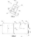
- the device 100 of the figure 1 comprises the two packings 102 and 103 defining between them the confined space 104.
- the confined space 104 is here delimited further by the membrane 108.
- the device 100 also comprises the two electrodes 106 arranged in the confined space 104
- the two electrodes 106 are respectively connected to the voltage source via an input 109 and to a ground 103 (here merged with the gasket 103) of the circuit, which allows the formation of the electric arc. between the two electrodes 106.
- the electrodes may have a radius of between 0.1 mm and 50 mm, preferably between 1 mm and 30 mm.
- the inlet 109 may consist of an insulated cable.
- FIG. 1 are also schematically represented the apparatus for regulating the temperature 105 of the fluid in the confined space and the pressure regulating apparatus 107.
- the electric circuit for generating an electric arc between the two electrodes 106 , its voltage source and inductance are not shown, but may be in accordance with Figures 2 to 4 which schematically show examples of the device 100.
- the device 100 of the figure 2 comprises the inductor 110.
- the voltage source comprises the capacitor 112.
- the capacitor 112 may have a capacitance greater than 1 ⁇ F, preferably greater than 10 ⁇ F. Such a capacity makes it possible to reach an energy causing the appearance of a subsonic arc.
- the electric discharge is called “subsonic” or “supersonic” depending on its formation rate.
- a “subsonic” discharge is typically associated with thermal processes: the arc propagates through gas bubbles created by the heating of the water. We speak of “slow” propagation of the electric discharge, typically of the order of 10 m / s. The main characteristics of a subsonic discharge are related to high energies involved (typically beyond several hundred Joules), thermal processes associated with a long time of application of the voltage and at low levels of energy. voltage (low electric field). In this discharge regime, the pressure wave propagates in a large volume of gas before spreading in the fluid.
- a “supersonic” discharge is typically associated with electronic processes. The discharge propagates in the water without a thermal process with a filamentary appearance.
- the capacitor 112 may have a capacity of less than 1000 ⁇ F, preferably less than 200 ⁇ F.
- the capacitor 112 is separated from the inductor by the spark gap 114 which can be initiated by the pulse generator 116. This makes it possible to control the discharges of the capacitor 112 and thus the pressure waves generated by the electric arc.
- the pulse generator 116 may be configured for wave repetition, as described later.
- the voltage source (i.e. the capacitor 112) is charged by a high voltage charger 120 provided in an auxiliary circuit 122 at a voltage U of between 1 and 500 kV, preferably between 50 and 200 kV.
- the auxiliary circuit is preferably located on the surface, and is then separable from the device.
- the device 100 of the figure 3 is different from the example of the figure 2 in that a Marx generator 118 replaces the capacitor 112 and the assembly (spark gap 114 + pulse generator 116).
- the generator Marx 118 allows during its discharge the creation of a supersonic electronic arc, imposing a higher voltage than the capacitor 112.
- the voltage source comprises the capacitor 112 of the figure 2 and the Marx generator 118 of the figure 3 .
- the pulse generator 116 primes the first spark gap 117 of the Marx generator 118.
- the device 100 further includes the ferrites 119 forming a saturable inductance in a path leading the capacitor directly to the inductor.
- the ferrites 119 are configured to be saturated once the Marx generator 118 is discharged. Once the ferrites 119 are saturated, only the capacitor 112 discharges. This allows a temporary isolation of the capacitor 112 and thus the passage (ie switching) of a supersonic arc to a subsonic arc.
- the device thus ensures a coupling between a supersonic and subsonic discharge.
- the subsonic discharge produced by the capacitor 112 occurs after a delay corresponding to the breakdown time of the generator Marx 118.
- the switching can be done in a time less than 1 s.
- the duration of the discharge produced by the Marx generator 118 is very short, lasting less than 1 microsecond, and amplitude greater than 100 kV.
- the various components of the device 100 are of adjustable characteristics, ie their characteristics can be modified before use as a function of the reservoir, or during use depending on the response or the progress of the fracturing.
- the coil 110 may be of adjustable inductance.
- the characteristics of the Marx generator 118 (capacity of each capacitor in parallel, number of capacitors operating) can be adjustable.
- the distance between the electrodes 106 preferably between 0.2 and 5 cm, more preferably between 1 and 3 cm, can also be adjustable.
- the capacitance of the capacitor 112 can also be adjustable. This makes it possible to have a device 100 adapted to the fracturing of any type of tank. Indeed, it is not necessary to replace the device 100 when changing the reservoir to be fractured (and that the material is different) because it is sufficient to modify one or more of the adjustable parameters. This also makes it possible to optimize the damage by modifying, possibly remotely, the parameters in use.
- the generation of the pressure wave can be decomposed into two phases: a pre-discharge phase S100 and a post-discharge phase S110, separated by the S105 appearance of the bow.
- the voltage drops. This fall corresponds to the discharge of the equivalent capacity of the energy bank or the Marx generator into the equivalent resistance of the device 100.
- the greater the equivalent resistance the best is the conservation of energy in the pre-breakdown phase.
- the configuration of electrodes can therefore, in each case (subsonic or supersonic) allow to obtain the least possible loss of energy. This corresponds to the optimization of the water heating in one case and the electric field in the other.
- the electric circuit can be modeled by a RLC circuit in oscillating mode.
- This current i ( t ) is a function of the breakdown voltage U B (dielectric breakdown of the medium) of the capacitor, the inductance and the resistance of the circuit.
- a pressure sensor has been used to visualize the waveforms of the pressures generated as a function of the frequency spectrum.
- This frequency spectrum can indeed be modified by the dielectric breakdown mode, by the parameters of the electric circuit, by the volume of gas, as well as by the nature of the liquid used.
- Two examples of frequency spectrum associated with a subsonic and supersonic discharge were tested. It appeared that the lower frequencies the spectrum has, the less diffuse the damage.
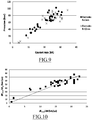
- the result of various experiments carried out shows a linear relation of d P max / d t p as a function of the current edge d i max / d t i , represented on the figure 10 .
- the current front has an influence on the pressure front. The slower the current front, the lower the pressure.
- the peak current i max is controlled by the available energy at the moment of the arc noted E b and by the inductance of the circuit L , these are the two parameters on which the user must act.
- the resistance R is considered very weak and the capacitance C is a function of the energy E b .
- the peak pressure generated is therefore controlled by the current i max (parameters E b and L ) and by the coefficient k 1 (function of the inter-electrode distance and the dielectric breakdown mode of the water). We can therefore act on E b , L and k 1 to obtain the desired pressure.
- the front of the pressure wave is thus controlled by the coefficients k 1 and k 2 and by the values of L and C (electrical circuit parameters).
- the geometry of the electrodes, with constant injected current, has no influence on the peak pressure generated, but may play a role in reducing the electrical losses in the pre-discharge phase.
- the above studies confirm the utility of introducing an inductance between the voltage source and one of the two electrodes to act on the pressure wave generated in the end.
- the studies also confirm the interest of having adjustable parameters, e.g. the inductance, the capacity of the capacitor, the characteristics of the generator of Marx. Indeed, the pressure wave depends on these parameters, the ability to adjust them to control the pressure wave.
- the electrode configuration consists of two spike electrodes (2.5 mm radius of curvature) and an inter-electrode distance of 3 mm.
- the insulating material used for the High Voltage bushing is PEEK 450G.
- the dielectric strength of the water is characterized by determining the pre-breakdown voltage U 50 , a voltage value which causes 50% hold and 50% start-up.
- the method used to determine this voltage U 50 is called "up and down”.
- Voltage levels are pre-selected and a series of tests is carried out at these different levels, the result of each test determining the next level: next higher level when held, next lower level when primed. It then takes about fifty attempts to acquire the U 50 value.
- the value denoted U 50 represents the average of a series of 50 shocks.
- Equivalent water resistance was determined using an experimental method and simulation using the COMSOL software.
- R water is determined by measuring the exponential decay of the voltage wave, as illustrated by the figure 11 .
- the value of the discharge constant corresponds to the time required for a 37% drop in the initial voltage value of the capacitor.
- the evolution of the conductivity of water as a function of temperature is not the same depending on the type of water used (pure, demineralised, tap or seawater for example). Indeed, the initial conductivity determines the influence of the temperature with respect to the posterior evolution of the conductivity. In our case we used demineralized water and the initial parameters were determined by experimentation.
- the resistance could be determined from Ohm's law.
- the objective of this part of the simulation tests was to characterize the HP enclosure in terms of voltage withstand and equivalent impedance (capacitance and resistance).
- E T 1 2 . VS . U 2 50
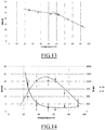
- the figure 14 presents the evolution of the breakdown voltage U b and the corresponding time T b as a function of the water temperature as well as the standard deviations.
- the interpretation of the variation of the parameter U b is more delicate. It takes into account the small variation of U 50 over the range 25 ° C - 60 ° C coupled with a significant decrease in the duration of application of the voltage wave.
- the voltage U b therefore increases over this temperature range. Beyond this temperature range, the breakdown voltage decreases significantly as the temperature increases from 60 ° C to 90 ° C. The duration of application of the voltage being further reduced, the breakdown voltage U b can only decrease.
- the set of parameters defined in the expression (1) is now determined experimentally. It is therefore possible to plot the evolution curve of the energy consumed E C in the pre-discharge phase as a function of the temperature, as illustrated in FIG. figure 15 .
- the mass enthalpy of vaporization is constant at the pressure of 1 bar and the variations of c p as a function of the temperature are given by the tables of the water. Therefore, the variations of E given by the expression (5) show that the higher the temperature increases, the less energy must be provided to vaporize a unit mass of water, as shown in figure 16 .
- the fracturing device can be used in a method of fracturing a hydrocarbon geological reservoir.
- the method includes electrical fracturing of the reservoir by the generation of an electric arc by the device, which induces a pressure wave leading to the fracturing.
- the process can understand the regulation of the temperature of a fluid in the confined space of the device, thanks to the temperature control device.
- the device can also be used in a hydrocarbon production process comprising the fracturing of a geological reservoir of hydrocarbons according to the preceding method.
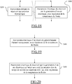
- the process of figure 18 includes static fracturing (S20) of the tank by hydraulic pressure. And the process of figure 18 also includes, before, during or after the static fracturing (S20) (these three possibilities being represented by the dashed lines on the figure 18 ), electrical fracturing (S10) of the tank by generating an electric arc in a well drilled in the tank, as described above.
- S20 static fracturing
- S10 electrical fracturing
- Static fracturing can be any type of static fracturing known from the prior art.
- the static fracturing (S20) may comprise, after the eventual drilling of a well in the reservoir, the injection of a fluid under high pressure into the well.
- Static fracturing (S20) thus creates one or more unidirectional cracks, typically deeper than those created by electrical fracturing (S10).
- the fluid can be water, a mud or a technical fluid with controlled viscosity enriched with hard agents (grains of sieved sand, or ceramic microbeads) which prevent the fracture network from closing on itself at the time of the pressure drop.
- hard agents grains of sieved sand, or ceramic microbeads
- Static fracturing may comprise a first injection phase in a well drilled with a fracturing fluid that contains thickeners, and a second phase that involves the periodic introduction of propant (ie a proppant) into the fracturing fluid to feed the fracture created by propelling.
- propant ie a proppant
- the second phase or its sub-phases involves the additional introduction of a reinforcement and / or consolidation material, thereby increasing the strength of the propant clusters formed in the fracturing fluid.
- Such static fracturing (S20) makes it possible to obtain fractures typically between 100 and 5000 meters.
- Static fracturing (S20) can precede electrical fracturing (S10).
- the pressure wave generated by the electrical fracturing (S10) can follow the course of the fluid introduced into the cracks created by the static fracturing (S20) and thus improve the damage.
- such an order between fractures (S20) and (S10) presents little risk of leaks.
- static fracturing (S20) can precede electrical fracturing (S10) by less than a week.
- the process of figure 19 includes the only electrical fracking (S10) of the tank, carried out in a reservoir where a well has already been drilled and has already been statically fractured.
- the process of figure 19 allows the damage of tanks already exploited after static fracturing.
- the process of figure 19 allows the exploitation of an abandoned reservoir because already exploited, potentially by reusing a well already drilled.
- the process of figure 19 corresponds to the process of figure 18 (where static fracturing (S20) corresponds to this preliminary static fracturing).
- the preliminary static fracturing may have been carried out according to the method of figure 18 .
- the process of figure 20 mainly involves the electrical fracturing (S10) of the reservoir by the generation of an electric arc in a fluid present in a well drilled in the reservoir (thus combined or not with a static fracturing, for example the static fracturing (S20) of the process of the figure 1 ).
- the electric arc induces a pressure wave whose rise time is greater than 0.1 ⁇ s, preferably greater than 10 ⁇ s.
- the process figure 20 improves the fracturing of the tank.
- the rise time of the pressure wave is the time required for the pressure wave to reach the pressure peak, i.e. the maximum value of the wave (also called “peak pressure").
- a rise time greater than 0.1 ⁇ s, preferably greater than 10 ⁇ s corresponds to a pressure wave which penetrates better into the tank.
- Such a pressure wave is particularly effective (ie the wave penetrates deeper) in the case of ductile materials, such as those composing shale gas reservoirs.
- the rise time is less than 1 ms, advantageously less than 500 ⁇ s.
- the pressure wave may have a maximum pressure of up to 10 kbar, preferably greater than 100 bar and / or less than 1000 bar. This may correspond to an energy stored between 10 J and 2 MJ, preferably between 10 kJ and 500 kJ.
- the well can be horizontal.
- the well may be horizontal and have a length preferably between 500 and 5000 m, preferably between 800 and 1200 m, for example at a depth between 1000 and 10000 m, for example between 3000 and 5000 m.
- Electric fracturing (S10) can be repeated in different treatment zones along the well. Indeed, with electric fracturing (S10), there is a pressure wave that generally penetrates less deeply than static fracturing. Thus, with electrical fracturing (S10), cracks of length less than 100 m, typically less than 50 m, and typically greater than 20 m, are typically obtained. For a well several hundred meters long, the repetition of electrical fracturing (S10) along the well allows damage along the well and therefore a better possible exploitation of the reservoir.
- each treatment zone or in the single treatment zone if it is unique, several arcs can be generated afterwards.
- the generation of an electric arc is repeated in a substantially fixed position. This improves the damage by repeating the pressure wave.
- the generated arcs can be the same or different.
- the arcs generated subsequently induce a pressure wave whose rise time is decreasing.
- the arches in succession can present an increasingly steep front, thus inducing a pressure wave having a rise time faster and faster.
- the first impulses have slower fronts to penetrate deeply, whereas the pulses to the stiffer fronts fracture closer to the well and more densely. This optimizes the damage.
- the first arcs can for example induce a pressure wave whose rise time is greater than 10 ⁇ s, preferably 100 ⁇ s.
- the last arcs can then induce a pressure wave whose rise time is less than the rise time of the first arcs, for example less than 10 ⁇ s or 100 ⁇ s.
- the first arcs comprise at least one arc, preferably a number less than 10,000 or even 1000, and the last arcs comprise at least one arc, preferably a number less than 10,000 or even 1000.
- the arcs can be generated at a frequency less than 100 Hz, preferably less than 10 Hz, and / or greater than 0.001 Hz, preferably greater than 0.01 Hz.
- the frequency of the arcs can be (substantially) equal to the resonant frequency of the material to be fractured in the tank. This ensures more effective damage.
- the reservoir may have a permeability less than 10 microdarcy.
- This may include a shale gas tank.
- the gas is typically adsorbed (up to 85% on Lewis Shale) and poorly trapped in pores.
- the low permeability of this type of reservoir does not make it possible to hope to directly produce trapped gases in such a medium, only the surface gas (adsorbed gas) can be produced.
- an effective electrical fracturing (S10) over a radius of 30 m along a horizontal well of 1000 m would allow a recovery of gas that can exceed 50 MNm 3 (assuming 26 Nm 3 of gas per m 3 of rock as suggested in the article "Porosity and Permeability of Eastern Devonian Shale gas” above).
- the fracturing process of any of the Figures 1 to 3 can thus be included in a hydrocarbon production process of the tank, typically shale gas.
- Electric fracturing may comprise the prior injection into the fluid of an agent improving the plasticity of the material constituting the reservoir.
- the agent may comprise a chemical additive.
- the chemical additive may be an agent inducing the rock fracture.
- the additive may include steam. This helps to further improve the fracturing.
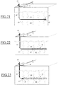
- electrical fracturing (S10) of the fracturing process of any of the Figures 18 to 20 will now be described with reference to Figures 21 to 23 .
- electrical fracturing (S10) of a tank 40 is carried out in which a horizontal well 43 has been drilled.
- Electrical fracturing (S10) is here combined with static fracturing, not specifically illustrated and possibly prior, which has induced major fractures 41 in the reservoir.
- the fracturing process makes it possible here to produce hydrocarbon by means of a production pipe situated at the surface, at the wellhead 45.
- the electric arc is generated at the level of a fracturing device 47, which may be in accordance with FIG. to the fracturing device 100 of the figure 1 .
- electrical fracturing induces secondary fractures 42 at the point where the arc is generated.
- the secondary fractures 42 are shorter but more diffuse than the main fractures 41.
- the electrical fracturing (S10) is repeated in different treatment zones along the well.
- the figure 21 indeed shows an initial phase of electrical fracturing (S10) downhole.
- the figure 22 shows an intermediate phase in the middle of wells.
- the figure 23 shows a final phase at the beginning of the well.
- the secondary fractures 42 are dispersed all around the well 43. It is then possible to recover the hydrocarbon surrounding these secondary fractures 42, a hydrocarbon potentially distant from the main fractures 41 and thus difficult to recover by a single static fracturing.
- the mobility of the fracturing device 47 which may be the particular device, makes it possible to fracture the reservoir all along the well.
- the device 47 is supplied in this example with a high voltage power supply 44 located at the surface and connected to the device 47 by the cables 46.
- the present invention is not limited to the examples described and shown, but it is capable of numerous variants accessible to those skilled in the art.
- the principles outlined above can be applied to the production of seismic data.
- the generation of the electric arc could alternatively induce a pressure wave having characteristics lower than those required for the fracturing of the reservoir. This can be done, for example, by adapting the charging voltage of the fracturing device and the charging voltage, and by varying the inductance.
- Such a seismic data production method can then comprise the reception of a reflection of the pressure wave, the reflected wave then being typically modulated by its passage through the material constituting the reservoir.
- the seismic data generating method can then also include analyzing the reflected wave to determine reservoir characteristics. We can then build a seismic survey based on the reception.
Landscapes
- Geology (AREA)
- Life Sciences & Earth Sciences (AREA)
- Engineering & Computer Science (AREA)
- Mining & Mineral Resources (AREA)
- Environmental & Geological Engineering (AREA)
- Fluid Mechanics (AREA)
- Physics & Mathematics (AREA)
- General Life Sciences & Earth Sciences (AREA)
- Geochemistry & Mineralogy (AREA)
- Physical Or Chemical Processes And Apparatus (AREA)
- Drilling And Exploitation, And Mining Machines And Methods (AREA)
- Geophysics And Detection Of Objects (AREA)
- Processing Of Solid Wastes (AREA)
Claims (15)
- Vorrichtung (100) zur Frakturierung einer geologischen Kohlenwasserstofflagerstätte, wobei die Vorrichtung folgendes umfasst:- zwei Dichtungen (102, 103) die zwischen einander einen geschlossenen Raum (104) in einem Bohrloch im Reservoir definieren;- ein Gerät zur Temperaturregelung eines Fluids innerhalb des geschlossenen Raums;- ein, im geschlossenen Raum angeordnetes Elektrodenpaar (106); und- eine elektrische Schaltung zur Erzeugung eines elektrischen Lichtbogens zwischen den beiden Elektroden, wobei die Schaltung mindestens eine, mit den Elektroden (106) verbundene Spannungsquelle (112, 118) umfasst, wobei die Vorrichtung dadurch gekennzeichnet ist, dass sie ferner eine Induktivitätsspule (110) zwischen der Spannungsquelle (112, 118) und einer der beiden Elektroden umfasst.
- Vorrichtung nach Anspruch 1, wobei das Temperaturregelungsgerät die Temperatur des Fluids regelt, um bei der Erzeugung eines elektrischen Lichtbogens die Energieeffizienz der Vorladungsphase zu optimieren.
- Vorrichtung nach Anspruch 2, wobei das Temperaturregelungsgerät die Temperatur des Fluids einen, zwischen 45 und 67°C, vorzugsweise höher als 50°C und/oder niedriger 62°C liegenden Wert hält.
- Vorrichtung nach Anspruch 3, wobei die Vorrichtung ferner ein Gerät zur Regelung des Fluiddrucks, im Wesentlichen auf den Atmosphärendruck, umfasst.
- Vorrichtung nach einem der vorhergehenden Ansprüche, wobei das Temperaturregelungsgerät ein Fluidkühlsystem umfasst.
- Vorrichtung nach einem der vorhergehenden Ansprüche, wobei die Induktivitätsspule (110) von kontrollierbarer Induktivität ist, die vorzugsweise zwischen 1 µH und 100 mH, noch bevorzugter zwischen 10 µH und 1 mH liegt.
- Vorrichtung nach einem der vorhergehenden Ansprüche, wobei die Spannungsquelle einen Kondensator (112) mit einer Kapazität von über 1 µF, vorzugsweise von über 10 µF umfasst.
- Vorrichtung nach Anspruch 7, wobei die Kapazität des Kondensators vorzugsweise auf weniger als 1000 µF, noch bevorzugter auf weniger als 200 µF einstellbar ist.
- Vorrichtung nach Ansprüchen 7 oder 8, wobei die Schaltung ferner einen Marx-Generator (118) und Ferrite (119) die eine sättigbare Induktivität in einem Weg bilden der den Kondensator direkt zur Induktivität führt, umfasst, wobei die Ferrite gesättigt sind sobald der Marx-Generator entladen ist.
- Vorrichtung nach Ansprüchen 7, 8 oder 9, wobei der Kondensator mittels einer, durch einen Impulsgenerator (116) zündbaren Funkenstrecke (114) von der Induktivität getrennt ist.
- Vorrichtung nach einem der vorhergehenden Ansprüche, wobei die Elektroden (106) einen, im Bereich von 0,1 mm und 50 mm, vorzugsweise von 1 mm und 30 mm liegenden Radius aufweisen.
- Vorrichtung nach einem der vorhergehenden Ansprüche, wobei die Vorrichtung mehrere Elektrodenpaare umfasst.
- Verfahren zur Frakturierung einer geologischen Kohlenwasserstofflagerstätte, wobei das Verfahren die elektrische Frakturierung (S 10) der Lagerstätte durch die Erzeugung eines elektrischen Lichtbogens, mittels der Vorrichtung nach einem der vorhergehenden Ansprüchen und, gleichzeitig, die Temperaturregelung eines Fluids innerhalb des geschlossenen Raums der Vorrichtung umfasst.
- Verfahren zur Herstellung von Kohlenwasserstoff, welches die Frakturierung einer geologischen Kohlenwasserstofflagerstätte nach Anspruch 13 umfasst.
- Verfahren zum Kalibrieren des Temperaturregelungsgeräts der Vorrichtung nach einem der Ansprüche 1 bis 12, das die folgenden Schritte umfasst:- das Bereitstellen der Vorrichtung, das Bestimmen einer Vor-Durchschlagspannung oberhalb welcher der elektrische Lichtbogen erzeugt wird, dann- das Messen der Durchschlagspannung an den Elektrodenanschlüssen und der Durchschlagzeit, in Abhängigkeit von der Temperatur des Fluids, unter Anwendung der Vor-Durchschlagspannung und durch das Verändern der Temperatur des Fluids, dann- das Ableiten der Energieeffizienz der Vorentladungsphase vom vorhergehenden Schritt, in Abhängigkeit von der Temperatur, dann- das Definieren einer Zieltemperatur oder eines Zieltemperaturbereichs für das Temperaturregelungsgerät, in Abhängigkeit von einer maximalen, im vorhergehenden Schritt abgeleiteten, Energieeffizienz.
Applications Claiming Priority (2)
| Application Number | Priority Date | Filing Date | Title |
|---|---|---|---|
| FR1255132A FR2991371B1 (fr) | 2012-06-01 | 2012-06-01 | Fracturation electrique amelioree d'un reservoir |
| PCT/EP2013/061407 WO2013178826A1 (fr) | 2012-06-01 | 2013-06-03 | Fracturation electrique amelioree d'un reservoir |
Publications (2)
| Publication Number | Publication Date |
|---|---|
| EP2859183A1 EP2859183A1 (de) | 2015-04-15 |
| EP2859183B1 true EP2859183B1 (de) | 2018-04-25 |
Family
ID=46889202
Family Applications (1)
| Application Number | Title | Priority Date | Filing Date |
|---|---|---|---|
| EP13726784.5A Not-in-force EP2859183B1 (de) | 2012-06-01 | 2013-06-03 | Verbessertes elektrisches aufbrechen einer lagerstätte |
Country Status (6)
| Country | Link |
|---|---|
| US (1) | US9988888B2 (de) |
| EP (1) | EP2859183B1 (de) |
| AR (1) | AR091242A1 (de) |
| FR (1) | FR2991371B1 (de) |
| RU (1) | RU2630000C2 (de) |
| WO (1) | WO2013178826A1 (de) |
Families Citing this family (9)
| Publication number | Priority date | Publication date | Assignee | Title |
|---|---|---|---|---|
| US10060716B2 (en) * | 2014-12-01 | 2018-08-28 | Matthew Creedican | Explosives manipulation using ultrasound |
| RU2663770C1 (ru) * | 2017-03-15 | 2018-08-09 | Федеральное государственное бюджетное учреждение науки Институт проблем управления им. В.А. Трапезникова Российской академии наук | Способ ударного воздействия на призабойную зону |
| RU2663766C1 (ru) * | 2017-03-15 | 2018-08-09 | Федеральное государственное бюджетное учреждение науки Институт проблем управления им. В.А. Трапезникова Российской академии наук | Устройство для ударного воздействия на призабойную зону |
| US10177696B1 (en) * | 2017-05-26 | 2019-01-08 | American Silver, Llc | Adjusting a distance between an electrode and a liquid |
| US11091991B1 (en) | 2018-05-25 | 2021-08-17 | Eden GeoPower Inc. | System and method for pulsed electrical reservoir stimulation |
| RU2705676C1 (ru) * | 2019-03-04 | 2019-11-11 | Общество с ограниченной ответственностью "Научно-исследовательский институт технических систем "Пилот" | Способ импульсной обработки продуктивного пласта при добыче углеводородного сырья и система управления, его осуществляющая |
| US10914156B2 (en) | 2019-05-30 | 2021-02-09 | Halliburton Energy Services, Inc. | Frac pulser system and method of use thereof |
| US11788394B2 (en) | 2021-07-15 | 2023-10-17 | Eden Geopower, Inc. | Systems and methods for deployment of electric-based fracturing tools in vertical wells |
| US11649710B2 (en) | 2021-07-15 | 2023-05-16 | Eden Geopower, Inc. | Downhole apparatus and system for electric-based fracturing |
Family Cites Families (18)
| Publication number | Priority date | Publication date | Assignee | Title |
|---|---|---|---|---|
| US4343356A (en) * | 1972-10-06 | 1982-08-10 | Sonics International, Inc. | Method and apparatus for treating subsurface boreholes |
| US4074758A (en) | 1974-09-03 | 1978-02-21 | Oil Recovery Corporation | Extraction method and apparatus |
| CA1095400A (en) * | 1976-05-03 | 1981-02-10 | Howard J. Rowland | In situ processing of organic ore bodies |
| US4164978A (en) | 1978-02-21 | 1979-08-21 | Winton Corporation | Oil extraction method |
| US4345650A (en) * | 1980-04-11 | 1982-08-24 | Wesley Richard H | Process and apparatus for electrohydraulic recovery of crude oil |
| US4706228A (en) | 1984-12-05 | 1987-11-10 | Southwest Research Institute | Asymmetrical lateral-force seismic source transducer |
| US4651311A (en) | 1984-12-05 | 1987-03-17 | Southwest Research Institute | Electrodeless spark discharge acoustic pulse transducer for borehole operation |
| ZA91612B (en) | 1990-04-20 | 1991-10-30 | Noranda Inc | Plasma blasting method |
| RU2090747C1 (ru) * | 1992-11-10 | 1997-09-20 | Акционерное общество открытого типа "Ноябрьскнефтегазгеофизика" | Способ элетрогидроимпульсного воздействия в нефтегазовых скважинах и устройство для его осуществления |
| US6427774B2 (en) * | 2000-02-09 | 2002-08-06 | Conoco Inc. | Process and apparatus for coupled electromagnetic and acoustic stimulation of crude oil reservoirs using pulsed power electrohydraulic and electromagnetic discharge |
| US20040060735A1 (en) * | 2002-09-26 | 2004-04-01 | Beckman Marvin Wayne | Impulse generator and method for perforating a cased wellbore |
| RU2263775C1 (ru) * | 2004-07-15 | 2005-11-10 | Московский государственный горный университет (МГГУ) | Электрогидроимпульсное скважинное устройство |
| US8061424B2 (en) | 2006-01-27 | 2011-11-22 | Schlumberger Technology Corporation | Method for hydraulic fracturing of subterranean formation |
| US8220537B2 (en) * | 2007-11-30 | 2012-07-17 | Chevron U.S.A. Inc. | Pulse fracturing device and method |
| RU76256U1 (ru) * | 2008-04-02 | 2008-09-20 | Игорь Владимирович Васильев | Устройство для восстановления производительности водоносной скважины |
| RU2373387C1 (ru) * | 2008-07-01 | 2009-11-20 | Общество с ограниченной ответственностью "НОВАС" | Способ воздействия на призабойную зону скважины на стадии освоения (варианты) и устройство для его осуществления |
| FR2972757B1 (fr) | 2011-03-14 | 2014-01-31 | Total Sa | Fracturation electrique et statique d'un reservoir |
| FR2972756B1 (fr) | 2011-03-14 | 2014-01-31 | Total Sa | Fracturation electrique d'un reservoir |
-
2012
- 2012-06-01 FR FR1255132A patent/FR2991371B1/fr not_active Expired - Fee Related
-
2013
- 2013-05-31 AR ARP130101938 patent/AR091242A1/es active IP Right Grant
- 2013-06-03 US US14/404,181 patent/US9988888B2/en not_active Expired - Fee Related
- 2013-06-03 WO PCT/EP2013/061407 patent/WO2013178826A1/fr not_active Ceased
- 2013-06-03 RU RU2014151494A patent/RU2630000C2/ru not_active IP Right Cessation
- 2013-06-03 EP EP13726784.5A patent/EP2859183B1/de not_active Not-in-force
Non-Patent Citations (1)
| Title |
|---|
| None * |
Also Published As
| Publication number | Publication date |
|---|---|
| US9988888B2 (en) | 2018-06-05 |
| FR2991371A1 (fr) | 2013-12-06 |
| RU2014151494A (ru) | 2016-07-27 |
| EP2859183A1 (de) | 2015-04-15 |
| FR2991371B1 (fr) | 2014-06-13 |
| US20150167438A1 (en) | 2015-06-18 |
| RU2630000C2 (ru) | 2017-09-05 |
| WO2013178826A1 (fr) | 2013-12-05 |
| AR091242A1 (es) | 2015-01-21 |
Similar Documents
| Publication | Publication Date | Title |
|---|---|---|
| EP2859183B1 (de) | Verbessertes elektrisches aufbrechen einer lagerstätte | |
| EP2686519B1 (de) | Elektrische und statische klüftung einer lagerstätte | |
| FR2972756A1 (fr) | Fracturation electrique d'un reservoir | |
| US10746006B2 (en) | Plasma sources, systems, and methods for stimulating wells, deposits and boreholes | |
| CA2706110C (en) | Pulse fracturing device and method | |
| FR2641322A1 (fr) | Procede de stimulation d'un puits au cours de l'extraction de petrole, et/ou de gaz, et/ou de condensats de gaz et dispositif pour la mise en oeuvre de ce procede | |
| Liu et al. | Influence of water conductivity on shock waves generated by underwater electrical wire explosion | |
| AU2017291945A1 (en) | Acoustic stimulation | |
| Zhang et al. | Investigation on large-scale tests of rock fracturing by high-voltage electric pulse with voltage as a variable | |
| He et al. | Experimental evaluation of near wellbore stimulation–using electrical explosion shockwave on tight sand reservoir | |
| Kochetkov et al. | Shock and detonation waves generated by a wire explosion in liquids and bubbled media | |
| EP3827518B1 (de) | Gepulste elektrische entladungsvorrichtung | |
| Sun et al. | Experimental study on rock fracturing by using pulsed power technology | |
| Kang et al. | Investigation of the Discharge Characteristics and Changes in Physical and Mechanical Properties of Rocks During the Electrical Breakdown Process | |
| RU2588086C2 (ru) | Электрический и статический разрыв пласта | |
| Bulgakov et al. | Experimental investigation into spherical plasma formations | |
| RU2836799C1 (ru) | Способ электрогидравлического воздействия на нефтяной пласт | |
| Huang et al. | Pulsed Shockwave: Effect of Different Discharge Energy and Repeat Number on Rock Mechanical Properties | |
| Nguyen et al. | Waterless Fracture Stimulation by Pulsed Power Plasma Using Nanoparticles: Experimental Insights from Sedimentary to Granite Geothermal Rocks | |
| Mallams | Plasma Characteristics with Respect to Highly Pressurized Drilling Applications | |
| RU2256072C1 (ru) | Способ интенсификации добычи углеводородов и устройство для его осуществления |
Legal Events
| Date | Code | Title | Description |
|---|---|---|---|
| PUAI | Public reference made under article 153(3) epc to a published international application that has entered the european phase |
Free format text: ORIGINAL CODE: 0009012 |
|
| 17P | Request for examination filed |
Effective date: 20141128 |
|
| AK | Designated contracting states |
Kind code of ref document: A1 Designated state(s): AL AT BE BG CH CY CZ DE DK EE ES FI FR GB GR HR HU IE IS IT LI LT LU LV MC MK MT NL NO PL PT RO RS SE SI SK SM TR |
|
| AX | Request for extension of the european patent |
Extension state: BA ME |
|
| RIN1 | Information on inventor provided before grant (corrected) |
Inventor name: MARTIN, JUSTIN Inventor name: REY-BETHBEDER, FRANCK Inventor name: REESS, THIERRY Inventor name: SYLVESTRE DE FERRON, ANTOINE |
|
| DAX | Request for extension of the european patent (deleted) | ||
| GRAP | Despatch of communication of intention to grant a patent |
Free format text: ORIGINAL CODE: EPIDOSNIGR1 |
|
| INTG | Intention to grant announced |
Effective date: 20171123 |
|
| GRAA | (expected) grant |
Free format text: ORIGINAL CODE: 0009210 |
|
| GRAS | Grant fee paid |
Free format text: ORIGINAL CODE: EPIDOSNIGR3 |
|
| AK | Designated contracting states |
Kind code of ref document: B1 Designated state(s): AL AT BE BG CH CY CZ DE DK EE ES FI FR GB GR HR HU IE IS IT LI LT LU LV MC MK MT NL NO PL PT RO RS SE SI SK SM TR |
|
| REG | Reference to a national code |
Ref country code: GB Ref legal event code: FG4D Free format text: NOT ENGLISH |
|
| REG | Reference to a national code |
Ref country code: CH Ref legal event code: EP |
|
| REG | Reference to a national code |
Ref country code: AT Ref legal event code: REF Ref document number: 993133 Country of ref document: AT Kind code of ref document: T Effective date: 20180515 |
|
| REG | Reference to a national code |
Ref country code: IE Ref legal event code: FG4D Free format text: LANGUAGE OF EP DOCUMENT: FRENCH |
|
| REG | Reference to a national code |
Ref country code: DE Ref legal event code: R096 Ref document number: 602013036450 Country of ref document: DE |
|
| REG | Reference to a national code |
Ref country code: NL Ref legal event code: MP Effective date: 20180425 |
|
| REG | Reference to a national code |
Ref country code: LT Ref legal event code: MG4D |
|
| PG25 | Lapsed in a contracting state [announced via postgrant information from national office to epo] |
Ref country code: NL Free format text: LAPSE BECAUSE OF FAILURE TO SUBMIT A TRANSLATION OF THE DESCRIPTION OR TO PAY THE FEE WITHIN THE PRESCRIBED TIME-LIMIT Effective date: 20180425 |
|
| PG25 | Lapsed in a contracting state [announced via postgrant information from national office to epo] |
Ref country code: BG Free format text: LAPSE BECAUSE OF FAILURE TO SUBMIT A TRANSLATION OF THE DESCRIPTION OR TO PAY THE FEE WITHIN THE PRESCRIBED TIME-LIMIT Effective date: 20180725 Ref country code: FI Free format text: LAPSE BECAUSE OF FAILURE TO SUBMIT A TRANSLATION OF THE DESCRIPTION OR TO PAY THE FEE WITHIN THE PRESCRIBED TIME-LIMIT Effective date: 20180425 Ref country code: SE Free format text: LAPSE BECAUSE OF FAILURE TO SUBMIT A TRANSLATION OF THE DESCRIPTION OR TO PAY THE FEE WITHIN THE PRESCRIBED TIME-LIMIT Effective date: 20180425 Ref country code: ES Free format text: LAPSE BECAUSE OF FAILURE TO SUBMIT A TRANSLATION OF THE DESCRIPTION OR TO PAY THE FEE WITHIN THE PRESCRIBED TIME-LIMIT Effective date: 20180425 Ref country code: LT Free format text: LAPSE BECAUSE OF FAILURE TO SUBMIT A TRANSLATION OF THE DESCRIPTION OR TO PAY THE FEE WITHIN THE PRESCRIBED TIME-LIMIT Effective date: 20180425 Ref country code: PL Free format text: LAPSE BECAUSE OF FAILURE TO SUBMIT A TRANSLATION OF THE DESCRIPTION OR TO PAY THE FEE WITHIN THE PRESCRIBED TIME-LIMIT Effective date: 20180425 Ref country code: NO Free format text: LAPSE BECAUSE OF FAILURE TO SUBMIT A TRANSLATION OF THE DESCRIPTION OR TO PAY THE FEE WITHIN THE PRESCRIBED TIME-LIMIT Effective date: 20180725 |
|
| PG25 | Lapsed in a contracting state [announced via postgrant information from national office to epo] |
Ref country code: LV Free format text: LAPSE BECAUSE OF FAILURE TO SUBMIT A TRANSLATION OF THE DESCRIPTION OR TO PAY THE FEE WITHIN THE PRESCRIBED TIME-LIMIT Effective date: 20180425 Ref country code: RS Free format text: LAPSE BECAUSE OF FAILURE TO SUBMIT A TRANSLATION OF THE DESCRIPTION OR TO PAY THE FEE WITHIN THE PRESCRIBED TIME-LIMIT Effective date: 20180425 Ref country code: HR Free format text: LAPSE BECAUSE OF FAILURE TO SUBMIT A TRANSLATION OF THE DESCRIPTION OR TO PAY THE FEE WITHIN THE PRESCRIBED TIME-LIMIT Effective date: 20180425 Ref country code: GR Free format text: LAPSE BECAUSE OF FAILURE TO SUBMIT A TRANSLATION OF THE DESCRIPTION OR TO PAY THE FEE WITHIN THE PRESCRIBED TIME-LIMIT Effective date: 20180726 |
|
| REG | Reference to a national code |
Ref country code: AT Ref legal event code: MK05 Ref document number: 993133 Country of ref document: AT Kind code of ref document: T Effective date: 20180425 |
|
| PG25 | Lapsed in a contracting state [announced via postgrant information from national office to epo] |
Ref country code: PT Free format text: LAPSE BECAUSE OF FAILURE TO SUBMIT A TRANSLATION OF THE DESCRIPTION OR TO PAY THE FEE WITHIN THE PRESCRIBED TIME-LIMIT Effective date: 20180827 |
|
| REG | Reference to a national code |
Ref country code: DE Ref legal event code: R119 Ref document number: 602013036450 Country of ref document: DE |
|
| PG25 | Lapsed in a contracting state [announced via postgrant information from national office to epo] |
Ref country code: EE Free format text: LAPSE BECAUSE OF FAILURE TO SUBMIT A TRANSLATION OF THE DESCRIPTION OR TO PAY THE FEE WITHIN THE PRESCRIBED TIME-LIMIT Effective date: 20180425 Ref country code: SK Free format text: LAPSE BECAUSE OF FAILURE TO SUBMIT A TRANSLATION OF THE DESCRIPTION OR TO PAY THE FEE WITHIN THE PRESCRIBED TIME-LIMIT Effective date: 20180425 Ref country code: RO Free format text: LAPSE BECAUSE OF FAILURE TO SUBMIT A TRANSLATION OF THE DESCRIPTION OR TO PAY THE FEE WITHIN THE PRESCRIBED TIME-LIMIT Effective date: 20180425 Ref country code: CZ Free format text: LAPSE BECAUSE OF FAILURE TO SUBMIT A TRANSLATION OF THE DESCRIPTION OR TO PAY THE FEE WITHIN THE PRESCRIBED TIME-LIMIT Effective date: 20180425 Ref country code: AT Free format text: LAPSE BECAUSE OF FAILURE TO SUBMIT A TRANSLATION OF THE DESCRIPTION OR TO PAY THE FEE WITHIN THE PRESCRIBED TIME-LIMIT Effective date: 20180425 Ref country code: DK Free format text: LAPSE BECAUSE OF FAILURE TO SUBMIT A TRANSLATION OF THE DESCRIPTION OR TO PAY THE FEE WITHIN THE PRESCRIBED TIME-LIMIT Effective date: 20180425 |
|
| REG | Reference to a national code |
Ref country code: CH Ref legal event code: PL |
|
| PG25 | Lapsed in a contracting state [announced via postgrant information from national office to epo] |
Ref country code: SM Free format text: LAPSE BECAUSE OF FAILURE TO SUBMIT A TRANSLATION OF THE DESCRIPTION OR TO PAY THE FEE WITHIN THE PRESCRIBED TIME-LIMIT Effective date: 20180425 Ref country code: IT Free format text: LAPSE BECAUSE OF FAILURE TO SUBMIT A TRANSLATION OF THE DESCRIPTION OR TO PAY THE FEE WITHIN THE PRESCRIBED TIME-LIMIT Effective date: 20180425 |
|
| PLBE | No opposition filed within time limit |
Free format text: ORIGINAL CODE: 0009261 |
|
| STAA | Information on the status of an ep patent application or granted ep patent |
Free format text: STATUS: NO OPPOSITION FILED WITHIN TIME LIMIT |
|
| REG | Reference to a national code |
Ref country code: BE Ref legal event code: MM Effective date: 20180630 |
|
| REG | Reference to a national code |
Ref country code: IE Ref legal event code: MM4A |
|
| GBPC | Gb: european patent ceased through non-payment of renewal fee |
Effective date: 20180725 |
|
| PG25 | Lapsed in a contracting state [announced via postgrant information from national office to epo] |
Ref country code: MC Free format text: LAPSE BECAUSE OF FAILURE TO SUBMIT A TRANSLATION OF THE DESCRIPTION OR TO PAY THE FEE WITHIN THE PRESCRIBED TIME-LIMIT Effective date: 20180425 Ref country code: LU Free format text: LAPSE BECAUSE OF NON-PAYMENT OF DUE FEES Effective date: 20180603 |
|
| 26N | No opposition filed |
Effective date: 20190128 |
|
| PG25 | Lapsed in a contracting state [announced via postgrant information from national office to epo] |
Ref country code: DE Free format text: LAPSE BECAUSE OF NON-PAYMENT OF DUE FEES Effective date: 20190101 Ref country code: IE Free format text: LAPSE BECAUSE OF NON-PAYMENT OF DUE FEES Effective date: 20180603 Ref country code: GB Free format text: LAPSE BECAUSE OF NON-PAYMENT OF DUE FEES Effective date: 20180725 Ref country code: CH Free format text: LAPSE BECAUSE OF NON-PAYMENT OF DUE FEES Effective date: 20180630 Ref country code: LI Free format text: LAPSE BECAUSE OF NON-PAYMENT OF DUE FEES Effective date: 20180630 Ref country code: FR Free format text: LAPSE BECAUSE OF NON-PAYMENT OF DUE FEES Effective date: 20180625 |
|
| PG25 | Lapsed in a contracting state [announced via postgrant information from national office to epo] |
Ref country code: SI Free format text: LAPSE BECAUSE OF FAILURE TO SUBMIT A TRANSLATION OF THE DESCRIPTION OR TO PAY THE FEE WITHIN THE PRESCRIBED TIME-LIMIT Effective date: 20180425 Ref country code: BE Free format text: LAPSE BECAUSE OF NON-PAYMENT OF DUE FEES Effective date: 20180630 |
|
| PG25 | Lapsed in a contracting state [announced via postgrant information from national office to epo] |
Ref country code: AL Free format text: LAPSE BECAUSE OF FAILURE TO SUBMIT A TRANSLATION OF THE DESCRIPTION OR TO PAY THE FEE WITHIN THE PRESCRIBED TIME-LIMIT Effective date: 20180425 |
|
| PG25 | Lapsed in a contracting state [announced via postgrant information from national office to epo] |
Ref country code: MT Free format text: LAPSE BECAUSE OF FAILURE TO SUBMIT A TRANSLATION OF THE DESCRIPTION OR TO PAY THE FEE WITHIN THE PRESCRIBED TIME-LIMIT Effective date: 20180425 |
|
| PG25 | Lapsed in a contracting state [announced via postgrant information from national office to epo] |
Ref country code: TR Free format text: LAPSE BECAUSE OF FAILURE TO SUBMIT A TRANSLATION OF THE DESCRIPTION OR TO PAY THE FEE WITHIN THE PRESCRIBED TIME-LIMIT Effective date: 20180425 |
|
| PG25 | Lapsed in a contracting state [announced via postgrant information from national office to epo] |
Ref country code: CY Free format text: LAPSE BECAUSE OF FAILURE TO SUBMIT A TRANSLATION OF THE DESCRIPTION OR TO PAY THE FEE WITHIN THE PRESCRIBED TIME-LIMIT Effective date: 20180425 Ref country code: HU Free format text: LAPSE BECAUSE OF FAILURE TO SUBMIT A TRANSLATION OF THE DESCRIPTION OR TO PAY THE FEE WITHIN THE PRESCRIBED TIME-LIMIT; INVALID AB INITIO Effective date: 20130603 Ref country code: MK Free format text: LAPSE BECAUSE OF NON-PAYMENT OF DUE FEES Effective date: 20180425 |
|
| PG25 | Lapsed in a contracting state [announced via postgrant information from national office to epo] |
Ref country code: IS Free format text: LAPSE BECAUSE OF FAILURE TO SUBMIT A TRANSLATION OF THE DESCRIPTION OR TO PAY THE FEE WITHIN THE PRESCRIBED TIME-LIMIT Effective date: 20180825 |