EP2859220B1 - Verbesserungen an windturbinen - Google Patents
Verbesserungen an windturbinen Download PDFInfo
- Publication number
- EP2859220B1 EP2859220B1 EP13726097.2A EP13726097A EP2859220B1 EP 2859220 B1 EP2859220 B1 EP 2859220B1 EP 13726097 A EP13726097 A EP 13726097A EP 2859220 B1 EP2859220 B1 EP 2859220B1
- Authority
- EP
- European Patent Office
- Prior art keywords
- hub
- wind turbine
- work platform
- plane
- hub plate
- Prior art date
- Legal status (The legal status is an assumption and is not a legal conclusion. Google has not performed a legal analysis and makes no representation as to the accuracy of the status listed.)
- Not-in-force
Links
Images




Classifications
-
- F—MECHANICAL ENGINEERING; LIGHTING; HEATING; WEAPONS; BLASTING
- F03—MACHINES OR ENGINES FOR LIQUIDS; WIND, SPRING, OR WEIGHT MOTORS; PRODUCING MECHANICAL POWER OR A REACTIVE PROPULSIVE THRUST, NOT OTHERWISE PROVIDED FOR
- F03D—WIND MOTORS
- F03D1/00—Wind motors with rotation axis substantially parallel to the air flow entering the rotor
- F03D1/06—Rotors
- F03D1/065—Rotors characterised by their construction elements
- F03D1/0658—Arrangements for fixing wind-engaging parts to a hub
-
- F—MECHANICAL ENGINEERING; LIGHTING; HEATING; WEAPONS; BLASTING
- F03—MACHINES OR ENGINES FOR LIQUIDS; WIND, SPRING, OR WEIGHT MOTORS; PRODUCING MECHANICAL POWER OR A REACTIVE PROPULSIVE THRUST, NOT OTHERWISE PROVIDED FOR
- F03D—WIND MOTORS
- F03D1/00—Wind motors with rotation axis substantially parallel to the air flow entering the rotor
- F03D1/06—Rotors
- F03D1/065—Rotors characterised by their construction elements
- F03D1/0691—Rotors characterised by their construction elements of the hub
-
- F—MECHANICAL ENGINEERING; LIGHTING; HEATING; WEAPONS; BLASTING
- F03—MACHINES OR ENGINES FOR LIQUIDS; WIND, SPRING, OR WEIGHT MOTORS; PRODUCING MECHANICAL POWER OR A REACTIVE PROPULSIVE THRUST, NOT OTHERWISE PROVIDED FOR
- F03D—WIND MOTORS
- F03D7/00—Controlling wind motors
- F03D7/02—Controlling wind motors the wind motors having rotation axis substantially parallel to the air flow entering the rotor
- F03D7/022—Adjusting aerodynamic properties of the blades
- F03D7/0224—Adjusting blade pitch
- F03D7/0228—Adjusting blade pitch of the blade tips only
-
- F—MECHANICAL ENGINEERING; LIGHTING; HEATING; WEAPONS; BLASTING
- F03—MACHINES OR ENGINES FOR LIQUIDS; WIND, SPRING, OR WEIGHT MOTORS; PRODUCING MECHANICAL POWER OR A REACTIVE PROPULSIVE THRUST, NOT OTHERWISE PROVIDED FOR
- F03D—WIND MOTORS
- F03D80/00—Details, components or accessories not provided for in groups F03D1/00 - F03D17/00
- F03D80/50—Maintenance or repair
-
- F—MECHANICAL ENGINEERING; LIGHTING; HEATING; WEAPONS; BLASTING
- F03—MACHINES OR ENGINES FOR LIQUIDS; WIND, SPRING, OR WEIGHT MOTORS; PRODUCING MECHANICAL POWER OR A REACTIVE PROPULSIVE THRUST, NOT OTHERWISE PROVIDED FOR
- F03D—WIND MOTORS
- F03D80/00—Details, components or accessories not provided for in groups F03D1/00 - F03D17/00
- F03D80/70—Bearing or lubricating arrangements
-
- F—MECHANICAL ENGINEERING; LIGHTING; HEATING; WEAPONS; BLASTING
- F05—INDEXING SCHEMES RELATING TO ENGINES OR PUMPS IN VARIOUS SUBCLASSES OF CLASSES F01-F04
- F05B—INDEXING SCHEME RELATING TO WIND, SPRING, WEIGHT, INERTIA OR LIKE MOTORS, TO MACHINES OR ENGINES FOR LIQUIDS COVERED BY SUBCLASSES F03B, F03D AND F03G
- F05B2250/00—Geometry
- F05B2250/30—Arrangement of components
- F05B2250/31—Arrangement of components according to the direction of their main axis or their axis of rotation
- F05B2250/314—Arrangement of components according to the direction of their main axis or their axis of rotation the axes being inclined in relation to each other
-
- Y—GENERAL TAGGING OF NEW TECHNOLOGICAL DEVELOPMENTS; GENERAL TAGGING OF CROSS-SECTIONAL TECHNOLOGIES SPANNING OVER SEVERAL SECTIONS OF THE IPC; TECHNICAL SUBJECTS COVERED BY FORMER USPC CROSS-REFERENCE ART COLLECTIONS [XRACs] AND DIGESTS
- Y02—TECHNOLOGIES OR APPLICATIONS FOR MITIGATION OR ADAPTATION AGAINST CLIMATE CHANGE
- Y02E—REDUCTION OF GREENHOUSE GAS [GHG] EMISSIONS, RELATED TO ENERGY GENERATION, TRANSMISSION OR DISTRIBUTION
- Y02E10/00—Energy generation through renewable energy sources
- Y02E10/70—Wind energy
- Y02E10/72—Wind turbines with rotation axis in wind direction
Definitions
- This invention relates to wind turbines.
- a typical wind turbine 10 is shown schematically in Figure 1 of the drawings. It comprises a tower 11, a nacelle 12 mounted to the top of the tower 11 and a rotor assembly 13 mounted to an upwind end 14 of the nacelle 12.
- the rotor assembly 13 comprises blades 15 mounted on a central hollow hub 16. Typically there are three blades but there could be two blades or four or more blades.
- the blades 15 turn with the hub 16 in a rotor plane to drive a generator within the nacelle 12 to produce electricity.
- the nacelle 12 can turn relative to the tower 11, the hub 16 can turn relative to the nacelle 12 and the blades 15 can turn relative to the hub 16. Specifically:
- the rotor axis 18 is typically set a few degrees above the horizontal 21.
- the blades 15 commonly have a negative cone angle with respect to the hub 16 as shown, i.e. the blades 15 are inclined in a slightly upwind direction moving radially outward from the hub 16. The cone angle is exaggerated in Figure 1 , and in reality would typically only be a few degrees at most.
- the pitch axis 19 extends radially from the rotor axis 18 when viewed along the rotor axis 18, the pitch axis 19 is not orthogonal to the rotor axis 18: the rotor plane is only approximately planar.
- a generally circular hub plate extends across each blade bearing.
- the hub plates are primarily stiffening bulkheads of the hub 16 but may also serve as work platforms for technicians working within the stationary hub during installation and maintenance of the wind turbine.
- a hub plate may serve as a work platform when the blade 15 associated with that hub plate is parked to hang downwardly from the hub in alignment with the tower.
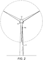
- a downwardly-hanging blade 15a is shown in Figure 2 .
- each hub plate may lie in a plane parallel to the associated blade bearing and thus orthogonal to the pitch axis 19 ( Figure 1 ).
- the pitch axis 19 of the downwardly-hanging blade may depart significantly from the vertical: individually and especially in combination, the inclined rotor axis 18 and the cone angle tend to tilt the pitch axis 19 of that downwardly-hanging blade in the upwind direction, away from the tower 11, as shown in Figure 1 . Consequently, a hub plate may be inclined too far from the horizontal to make an ideal work platform.
- DE 202004003521 U1 and EP 1930584 A2 provide examples of a wind turbine hub.
- the invention resides in a wind turbine as defined in claim 1.
- the plane of the work platform is preferably substantially parallel to the horizontal plane. However, angles of up to approximately seven degrees may be acceptable. In a particular embodiment described in detail later, the work platform is inclined at approximately five degrees to the horizontal. Angles between zero and five degrees are considered preferable.
- the work platform When the wind turbine blade is parked in a downwardly direction in alignment with the tower, the work platform provides a convenient platform for maintenance personnel to use when installing or servicing components in or around the hub.
- the work platform preferably includes one or more manholes for providing access between the hub and the blade.
- the rotor axis of the wind turbine is typically inclined upwardly relative to the horizontal plane by an angle of approximately eleven degrees.
- the work platform may be suitably inclined inwardly with respect to the hub moving parallel to the rotor axis in a direction from the hub towards the nacelle.
- the hub plate preferably comprises a substantially circular outer flange for connecting the hub plate to the hub.
- the outer flange suitably lies in a plane parallel to the bearing plane. Accordingly, the work platform is inclined relative to the plane of the outer flange.
- the outer flange is mounted between the hub and the pitch bearing.
- the pitch bearing preferably comprises an inner ring and an outer ring and the outer flange is preferably mounted to the inner ring. Accordingly, the blade is preferably mounted to the outer ring. It will however be appreciated that the hub plate may be mounted to the outer ring and the blade mounted to the inner ring in other embodiments.
- the hub plate may comprise a peripheral sidewall between the work platform and the outer flange.
- the profile of the sidewall preferably varies about the periphery of the work platform in accordance with the inclination of the work platform relative to the outer flange.
- the peripheral sidewall extends generally towards the rotor blade on an inboard side of the work platform nearest the nacelle and extends generally towards the hub on an outboard side of the platform furthest from the nacelle.
- a majority of the work platform is contained within a cylindrical space defined by an inner circumference of the annular pitch bearing and bound by a pair of opposed planes defined respectively by upper and lower faces of the annular pitch bearing.
- 'a majority' of the work platform may include all of the work platform.
- the inventive concept includes a wind farm comprising a plurality of wind turbines as described above.
- the inventive concept also includes a hub plate for a wind turbine, as defined in claim 12.
- FIGS. 1 and 2 which are, respectively, schematic side and front views of a wind turbine, have already been described above by way of background to the invention.
- FIG. 3 which shows a hub 30 of a wind turbine according to the present invention
- three blades are connected to the hub 30, but only two blades 32a and 32b are visible in the partial cross-sectional view of Figure 3 .
- Hub plates 34 in the form of stiffening bulkheads, are mounted at the interface between the hub 30 and the respective blades 32a, 32b.
- the hub plates 34 are generally circular and have a front face 36 that faces the hub 30 and a rear face 38 that faces the respective blade 32a, 32b.
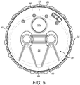
- the front face 36 is shown more clearly in Figure 4 and the rear face 38 is shown more clearly in Figure 5 .
- an annular pitch bearing 40 is mounted between the hub plate 34 and the blade 32a. Whilst not shown in Figure 3 , a similar pitch bearing is provided between the respective hub plates and blades of the other two blades.
- the pitch bearing 40 is shown more clearly in Figure 3A , which is an enlarged view of the part of Figure 3 within the dashed box 42.
- the pitch bearing 40 comprises an inner ring 44 and an outer ring 45, with two series of balls 46 provided in-between.
- the hub plate 34 is mounted between the hub 30 and the inner ring 44, and this assembly is fixed in place by a plurality of bolts 48 and associated nuts.
- the bolts 48 are received in a series of circularly arranged, and mutually aligned holes 49 provided in the hub 30, the hub plate 34 and the inner ring 44 respectively.
- the series of holes 49 in the hub plate 34 are provided in a circular outer flange 50 of the hub plate 34, as shown more clearly in Figures 4 and 5 .
- a root end 52 of the blade 32a is secured to the outer ring 45 of the pitch bearing 40 by a plurality of pins/bolts 54, which are received in a series of circularly arranged, and mutually aligned holes provided in the root end 52 of the blade 32a and the outer ring 45 of the pitch bearing 40.
- the hub plate 34 comprises a central, substantially circular and flat work platform 56.
- the work platform 56 includes a manhole 58a, which provide service access to the interior of the hub 30 or blade 32a for maintenance personnel.
- the work platform 56 is surrounded by a circumferential sidewall 60.
- the circumferential sidewall 60 extends between the work platform 56 and the outer circular flange 50 of the hub plate 34, as shown best in Figures 4 and 5 .
- the work platform 56 and the outer circular flange 50 are formed as a single casting of steel.
- the work platform 56 of the hub plate 34 in this example is inclined relative to the plane of the outer circular flange 50, and hence is inclined relative to the plane of the pitch bearing 40 in order that the work platform 56 is substantially horizontal when the blade 32a is parked in a substantially downward direction, parallel to the tower, as shown in Figure 3 .
- the work platform 56 is inclined inwardly with respect to hollow interior of the hub 30 moving parallel to the rotor axis 62 in a direction from the hub 30 towards the nacelle (not shown), as indicated by the arrow 64 in Figure 3 .
- the hub plate 34 is arranged such that the work platform 56 is inclined at approximately five degrees to a horizontal plane 66, as represented by the line 67, when the blade 32a is parked in this position.
- This level of inclination is considered to be substantially horizontal, and provides a sufficiently level surface for maintenance personnel to stand on when installing or servicing nearby components, such as components of the pitch mechanism.
- the rotor axis 62 is typically inclined at about eleven degrees to the horizontal, so ignoring any additional inclination due to cone angle, it will be appreciated that the work platform 56 of the hub plate 34 is significantly less inclined relative to the horizontal than prior art hub plates, which are arranged in the plane of the pitch bearing 40, and hence are inclined to the horizontal at least by the same amount as the rotor axis 62 when the blade 32a is downwardly extending.
- the profile of the circumferential sidewall 60 varies about the periphery of the work platform 56 in accordance with the inclination of the work platform 56 relative to the plane of the circular outer flange 50.
- the sidewall 60 extends generally upwards from the rear face 38 ( Figure 5 ) of the hub plate 34, i.e. generally towards the blade 32a, 32b, whilst at an outboard side 70 of the hub plate 34, the sidewall 50 extends generally upwards from the front face 36 ( Figure 4 ) of the hub plate 34, i.e. towards the hub 30.
- FIG. 6 this shows the pitch bearing 40 mounted to the circular outer flange 50 ( Figure 5 ) of the hub plate 34.
- Figure 6 also shows a pair of hydraulic actuators 76 of the pitch mechanism.
- the actuators 76 each include a piston 77 and a cylinder 78.
- the cylinders 78 of the respective actuators 76 are attached to mounting points 79 on the hub plate 34 respectively via a pair of brackets 80.
- the respective pistons 77 are connected to a crossbar 82 of a coupling ring 83, to which the blade 32a is attached.
- the blade 32a is caused to turn about its pitch axis by extending one of the pistons 77 relative to its cylinder 78 and lengthening the other piston 77 relative to its cylinder 78.
- the sidewall 60 of the hub plate 34 may be configured differently in other embodiments.
- the sidewall 60 could be very shallow or non-existent. This would require the sidewall 60 at the inboard side 68 of the hub plate 34 to be deeper. This in turn would result in the work platform 56 protruding significantly from the inner cylindrical space 72 defined by the pitch bearing 40.
- the work platform 56 also serves as a stiffening bulkhead
- a separate work platform may be attached to the hub plate.
- the hub plate may resemble a prior art hub plate, i.e. in which the plate is substantially parallel to the plane of the pitch bearing, but this hub plate could have an additional work platform attached, which is configured to be substantially horizontal when the blade is parked downwardly.
Landscapes
- Engineering & Computer Science (AREA)
- Life Sciences & Earth Sciences (AREA)
- Sustainable Development (AREA)
- Sustainable Energy (AREA)
- Chemical & Material Sciences (AREA)
- Combustion & Propulsion (AREA)
- Mechanical Engineering (AREA)
- General Engineering & Computer Science (AREA)
- Physics & Mathematics (AREA)
- Fluid Mechanics (AREA)
- Wind Motors (AREA)
Claims (14)
- Windturbine (10), umfassend:einen Turm (11);eine Gondel (12) montiert auf der Spitze des Turms;einen Rotor (13) montiert an der Gondel, wobei der Rotor zwei oder mehr Rotorblätter (32a, 32b) umfasst, die an einer zentralen Nabe (16) montiert sind, wobei die Nabe zwei oder mehr ringförmige Pitchlager (40) trägt, die entsprechend mit den zwei oder mehr Rotorblättern assoziiert sind, wobei jedes Pitchlager eine Lagerebene definiert, die unter einem ersten Winkel in Bezug auf eine horizontale Ebene geneigt ist, wenn das entsprechende Rotorblatt in eine Abwärtsrichtung in einer Richtung mit dem Turm orientiert ist, wobei: jedes Pitchlager von einer Nabenplatte (34) umfasst ist; und eine Arbeitsplattform (56), die in die Nabenplatte eingebaut oder an der Nabenplatte montiert ist, im Allgemeinen in einer Ebene unter einem zweiten Winkel zu der horizontalen Ebene liegt, wenn das entsprechende Rotorblatt in der Abwärtsrichtung in Richtung mit dem Turm orientiert ist, wobei der zweite Winkel kleiner als der erste Winkel ist,dadurch gekennzeichnet, dassein Großteil der Arbeitsplattform innerhalb eines zylindrischen Raumes enthalten ist, der mittels eines Innenumfangs des ringförmigen Pitchlagers definiert ist und mittels eines Paares gegenüberliegender Ebenen begrenzt ist, die entsprechend von den oberen und unteren Oberflächen des ringförmigen Pitchlagers definiert sind.
- Windturbine nach Anspruch 1, wobei die Ebene der Arbeitsplattform im Wesentlichen parallel zu der horizontalen Ebene liegt.
- Windturbine nach Anspruch 1 oder nach Anspruch 2, wobei der zweite Winkel ungefähr fünf Grad oder weniger ist.
- Windturbine nach einem der vorhergehenden Ansprüche, wobei die Arbeitsplattform nach innen geneigt ist in Bezug auf die Nabe, die sich parallel zu einer Rotorachse (62) der Windturbine in einer Richtung von der Nabe abwärts auf die Gondel zu bewegt.
- Windturbine nach einem der vorhergehenden Ansprüche, wobei die Nabenplatte einen im Wesentlichen kreisförmigen äußeren Flansch (50) zum Verbinden der Nabenplatte mit der Nabe umfasst, wobei der äußere Flansch in einer Ebene parallel zu der Lagerebene liegt.
- Windturbine nach Anspruch 5, wobei der äußere Flansch zwischen der Nabe und dem Pitchlager montiert ist.
- Windturbine nach Anspruch 6, wobei das Pitchlager einen Innenring (44) und einen Außenring (45) umfasst und der äußere Flansch an dem Innenring montiert ist.
- Windturbine nach einem der Ansprüche 5 bis 7, wobei die Nabenplatte eine periphere Seitenwand zwischen der Arbeitsplattform und dem äußeren Flansch umfasst.
- Windturbine nach Anspruch 8, wobei das Profil der Seitenwand um die Peripherie der Arbeitsplattform in Übereinstimmung mit der Neigung der Arbeitsplattform relativ zu dem äußeren Flansch variiert.
- Windturbine nach Anspruch 9, wobei die periphere Seitenwand sich in Richtung auf das Rotorblatt auf einer innenliegenden Seite der Arbeitsplattform am nächsten zu der Gondel erstreckt und sich in Richtung auf die Nabe auf einer außenliegenden Seite der Plattform am weitesten von der Gondel entfernt erstreckt.
- Windenergiepark umfassend eine Vielzahl von Windturbinen (10) nach einem der vorhergehenden Ansprüche.
- Nabenplatte (34) für eine Windturbine (10), wobei die Nabenplatte umfasst:eine Arbeitsplattform (56), die eine erste Ebene definiert; undeinen im Wesentlichen kreisförmigen äußeren Flansch (50), der die Arbeitsplattform mindestens teilweise umgibt, wobei der äußere Flansch eine zweite Ebene definiert und Mittel zum Montieren der Nabenplatte an einer Nabe der Windturbine an einer Schnittstelle zwischen der Nabe und einem Rotorblatt bereitstellt;wobei die erste Ebene relativ zu der zweiten Ebene geneigt ist, wobei die Nabenplatte an einem ringförmigen Pitchlager (40) montiert ist, wobei ein Großteil der Arbeitsplattform innerhalb eines zylindrischen Raumes enthalten ist, der mittels eines Innenumfangs des ringförmigen Pitchlagers definiert ist und mittels eines Paares von gegenüberliegenden Ebenen begrenzt ist, die entsprechend von den oberen und unteren Oberflächen des ringförmigen Pitchlagers definiert sind.
- Nabe für eine Windturbine, umfassend eine Nabenplatte nach Anspruch 12.
- Windturbine, umfassend eine Nabe nach Anspruch 13.
Applications Claiming Priority (3)
| Application Number | Priority Date | Filing Date | Title |
|---|---|---|---|
| US201261657845P | 2012-06-10 | 2012-06-10 | |
| DKPA201270389 | 2012-07-02 | ||
| PCT/DK2013/050122 WO2013185765A1 (en) | 2012-06-10 | 2013-05-01 | Improvements relating to wind turbines |
Publications (2)
| Publication Number | Publication Date |
|---|---|
| EP2859220A1 EP2859220A1 (de) | 2015-04-15 |
| EP2859220B1 true EP2859220B1 (de) | 2017-09-20 |
Family
ID=49757596
Family Applications (1)
| Application Number | Title | Priority Date | Filing Date |
|---|---|---|---|
| EP13726097.2A Not-in-force EP2859220B1 (de) | 2012-06-10 | 2013-05-01 | Verbesserungen an windturbinen |
Country Status (4)
| Country | Link |
|---|---|
| US (1) | US9587623B2 (de) |
| EP (1) | EP2859220B1 (de) |
| ES (1) | ES2644304T3 (de) |
| WO (1) | WO2013185765A1 (de) |
Families Citing this family (6)
| Publication number | Priority date | Publication date | Assignee | Title |
|---|---|---|---|---|
| CN104234945B (zh) * | 2014-09-23 | 2016-09-14 | 国家电网公司 | 风力发电机及其叶片连接轴承 |
| DK3267033T3 (da) * | 2016-07-06 | 2019-07-01 | Siemens Gamesa Renewable Energy As | Vindmølle |
| US11187206B2 (en) | 2017-10-17 | 2021-11-30 | Vestas Wind Systems A/S | Pitch system for a wind turbine |
| US11454219B2 (en) | 2019-05-10 | 2022-09-27 | General Electric Company | Rotor assembly having a pitch bearing with a stiffener ring |
| US10794357B1 (en) * | 2020-04-01 | 2020-10-06 | Kevin Pyne | Conical wind turbine assembly |
| EP4071349B1 (de) * | 2021-04-09 | 2025-12-31 | Siemens Gamesa Renewable Energy A/S | Plattform für eine nabe einer windturbine |
Citations (1)
| Publication number | Priority date | Publication date | Assignee | Title |
|---|---|---|---|---|
| EP1930584A2 (de) * | 2006-11-22 | 2008-06-11 | Fuji Jukogyo Kabushiki Kaisha | Nabe für eine Windenergieanlage mit horizontaler Achse |
Family Cites Families (5)
| Publication number | Priority date | Publication date | Assignee | Title |
|---|---|---|---|---|
| USRE41326E1 (en) * | 2003-04-12 | 2010-05-11 | General Electric Company | Reinforced hub for the rotor of a wind energy turbine |
| DE202004003521U1 (de) * | 2004-03-06 | 2004-06-24 | W2E Wind To Engergy Gmbh | Innenbegehbare Rotornabe |
| US8061999B2 (en) * | 2008-11-21 | 2011-11-22 | General Electric Company | Spinner-less hub access and lifting system for a wind turbine |
| US9631605B2 (en) | 2010-11-26 | 2017-04-25 | Vestas Wind Systems A/S | Pitch system for a wind turbine |
| US9074581B2 (en) * | 2012-06-12 | 2015-07-07 | General Electric Company | Cone angle insert for wind turbine rotor |
-
2013
- 2013-05-01 ES ES13726097.2T patent/ES2644304T3/es active Active
- 2013-05-01 US US14/406,981 patent/US9587623B2/en not_active Expired - Fee Related
- 2013-05-01 EP EP13726097.2A patent/EP2859220B1/de not_active Not-in-force
- 2013-05-01 WO PCT/DK2013/050122 patent/WO2013185765A1/en not_active Ceased
Patent Citations (1)
| Publication number | Priority date | Publication date | Assignee | Title |
|---|---|---|---|---|
| EP1930584A2 (de) * | 2006-11-22 | 2008-06-11 | Fuji Jukogyo Kabushiki Kaisha | Nabe für eine Windenergieanlage mit horizontaler Achse |
Also Published As
| Publication number | Publication date |
|---|---|
| WO2013185765A1 (en) | 2013-12-19 |
| US9587623B2 (en) | 2017-03-07 |
| US20150110631A1 (en) | 2015-04-23 |
| ES2644304T3 (es) | 2017-11-28 |
| EP2859220A1 (de) | 2015-04-15 |
Similar Documents
| Publication | Publication Date | Title |
|---|---|---|
| US9587623B2 (en) | Wind turbines | |
| US9617981B2 (en) | Wind turbine blade bearing removal apparatus and method | |
| EP2775137B1 (de) | System und verfahren zur re-indizierung eines blattlagers einer windkraftanlage | |
| EP3394427B1 (de) | Verfahren zum montieren oder demontieren einer windturbinenkomponente einer mehrrotor-windturbine | |
| EP2344753B1 (de) | Wartungskran für eine windturbine | |
| US10830204B2 (en) | Counterweight system for balanced hub wind turbine blade installation | |
| US7614850B2 (en) | Apparatus for assembling rotary machines | |
| EP3653870B1 (de) | Blattlageranordnung | |
| US9464625B2 (en) | Wind turbine | |
| CN103423100B (zh) | 在生产或安装期间旋转风力涡轮机的叶片或叶片部件的方法和设备 | |
| WO2017108049A1 (en) | Methods for mounting or dismounting wind turbine components of a multirotor wind turbine | |
| KR20190002686A (ko) | 풍력 발전 설비-로터 블레이드 및 이를 포함하는 풍력 발전 설비 | |
| US10641042B2 (en) | External ladder assembly for wind turbine nacelle | |
| EP3625451B1 (de) | Turmanordnung mit einem turmflansch | |
| CA2884334C (en) | A wind turbine on a rotating pedestal | |
| US12281636B2 (en) | Method of servicing or installing a component of a wind turbine using a crane | |
| EP2532879A1 (de) | Montage und/oder Instandhaltung einer Windturbine | |
| US11788514B2 (en) | Wind power plant with supporting structure | |
| US20180328343A1 (en) | Tower Assembly for a Wind Turbine |
Legal Events
| Date | Code | Title | Description |
|---|---|---|---|
| PUAI | Public reference made under article 153(3) epc to a published international application that has entered the european phase |
Free format text: ORIGINAL CODE: 0009012 |
|
| 17P | Request for examination filed |
Effective date: 20150107 |
|
| AK | Designated contracting states |
Kind code of ref document: A1 Designated state(s): AL AT BE BG CH CY CZ DE DK EE ES FI FR GB GR HR HU IE IS IT LI LT LU LV MC MK MT NL NO PL PT RO RS SE SI SK SM TR |
|
| AX | Request for extension of the european patent |
Extension state: BA ME |
|
| RAP1 | Party data changed (applicant data changed or rights of an application transferred) |
Owner name: VESTAS WIND SYSTEMS A/S |
|
| DAX | Request for extension of the european patent (deleted) | ||
| 17Q | First examination report despatched |
Effective date: 20160912 |
|
| RIC1 | Information provided on ipc code assigned before grant |
Ipc: F03D 1/06 20060101AFI20170517BHEP Ipc: F03D 80/70 20160101ALI20170517BHEP |
|
| GRAP | Despatch of communication of intention to grant a patent |
Free format text: ORIGINAL CODE: EPIDOSNIGR1 |
|
| INTG | Intention to grant announced |
Effective date: 20170628 |
|
| GRAS | Grant fee paid |
Free format text: ORIGINAL CODE: EPIDOSNIGR3 |
|
| GRAA | (expected) grant |
Free format text: ORIGINAL CODE: 0009210 |
|
| AK | Designated contracting states |
Kind code of ref document: B1 Designated state(s): AL AT BE BG CH CY CZ DE DK EE ES FI FR GB GR HR HU IE IS IT LI LT LU LV MC MK MT NL NO PL PT RO RS SE SI SK SM TR |
|
| REG | Reference to a national code |
Ref country code: GB Ref legal event code: FG4D |
|
| RIN1 | Information on inventor provided before grant (corrected) |
Inventor name: CHRISTOFFERSEN, LEIF Inventor name: NEUBAUER, JESPER LYKKEGAARD Inventor name: BAUN, TORBEN LADEGAARD |
|
| REG | Reference to a national code |
Ref country code: CH Ref legal event code: EP |
|
| REG | Reference to a national code |
Ref country code: AT Ref legal event code: REF Ref document number: 930366 Country of ref document: AT Kind code of ref document: T Effective date: 20171015 |
|
| REG | Reference to a national code |
Ref country code: IE Ref legal event code: FG4D |
|
| REG | Reference to a national code |
Ref country code: DE Ref legal event code: R096 Ref document number: 602013026836 Country of ref document: DE |
|
| REG | Reference to a national code |
Ref country code: ES Ref legal event code: FG2A Ref document number: 2644304 Country of ref document: ES Kind code of ref document: T3 Effective date: 20171128 |
|
| REG | Reference to a national code |
Ref country code: NL Ref legal event code: MP Effective date: 20170920 |
|
| PG25 | Lapsed in a contracting state [announced via postgrant information from national office to epo] |
Ref country code: NO Free format text: LAPSE BECAUSE OF FAILURE TO SUBMIT A TRANSLATION OF THE DESCRIPTION OR TO PAY THE FEE WITHIN THE PRESCRIBED TIME-LIMIT Effective date: 20171220 Ref country code: FI Free format text: LAPSE BECAUSE OF FAILURE TO SUBMIT A TRANSLATION OF THE DESCRIPTION OR TO PAY THE FEE WITHIN THE PRESCRIBED TIME-LIMIT Effective date: 20170920 Ref country code: LT Free format text: LAPSE BECAUSE OF FAILURE TO SUBMIT A TRANSLATION OF THE DESCRIPTION OR TO PAY THE FEE WITHIN THE PRESCRIBED TIME-LIMIT Effective date: 20170920 Ref country code: SE Free format text: LAPSE BECAUSE OF FAILURE TO SUBMIT A TRANSLATION OF THE DESCRIPTION OR TO PAY THE FEE WITHIN THE PRESCRIBED TIME-LIMIT Effective date: 20170920 Ref country code: HR Free format text: LAPSE BECAUSE OF FAILURE TO SUBMIT A TRANSLATION OF THE DESCRIPTION OR TO PAY THE FEE WITHIN THE PRESCRIBED TIME-LIMIT Effective date: 20170920 |
|
| REG | Reference to a national code |
Ref country code: LT Ref legal event code: MG4D |
|
| REG | Reference to a national code |
Ref country code: AT Ref legal event code: MK05 Ref document number: 930366 Country of ref document: AT Kind code of ref document: T Effective date: 20170920 |
|
| PG25 | Lapsed in a contracting state [announced via postgrant information from national office to epo] |
Ref country code: BG Free format text: LAPSE BECAUSE OF FAILURE TO SUBMIT A TRANSLATION OF THE DESCRIPTION OR TO PAY THE FEE WITHIN THE PRESCRIBED TIME-LIMIT Effective date: 20171220 Ref country code: GR Free format text: LAPSE BECAUSE OF FAILURE TO SUBMIT A TRANSLATION OF THE DESCRIPTION OR TO PAY THE FEE WITHIN THE PRESCRIBED TIME-LIMIT Effective date: 20171221 Ref country code: RS Free format text: LAPSE BECAUSE OF FAILURE TO SUBMIT A TRANSLATION OF THE DESCRIPTION OR TO PAY THE FEE WITHIN THE PRESCRIBED TIME-LIMIT Effective date: 20170920 Ref country code: LV Free format text: LAPSE BECAUSE OF FAILURE TO SUBMIT A TRANSLATION OF THE DESCRIPTION OR TO PAY THE FEE WITHIN THE PRESCRIBED TIME-LIMIT Effective date: 20170920 |
|
| PG25 | Lapsed in a contracting state [announced via postgrant information from national office to epo] |
Ref country code: NL Free format text: LAPSE BECAUSE OF FAILURE TO SUBMIT A TRANSLATION OF THE DESCRIPTION OR TO PAY THE FEE WITHIN THE PRESCRIBED TIME-LIMIT Effective date: 20170920 |
|
| PG25 | Lapsed in a contracting state [announced via postgrant information from national office to epo] |
Ref country code: RO Free format text: LAPSE BECAUSE OF FAILURE TO SUBMIT A TRANSLATION OF THE DESCRIPTION OR TO PAY THE FEE WITHIN THE PRESCRIBED TIME-LIMIT Effective date: 20170920 Ref country code: CZ Free format text: LAPSE BECAUSE OF FAILURE TO SUBMIT A TRANSLATION OF THE DESCRIPTION OR TO PAY THE FEE WITHIN THE PRESCRIBED TIME-LIMIT Effective date: 20170920 Ref country code: PL Free format text: LAPSE BECAUSE OF FAILURE TO SUBMIT A TRANSLATION OF THE DESCRIPTION OR TO PAY THE FEE WITHIN THE PRESCRIBED TIME-LIMIT Effective date: 20170920 |
|
| REG | Reference to a national code |
Ref country code: FR Ref legal event code: PLFP Year of fee payment: 6 |
|
| PG25 | Lapsed in a contracting state [announced via postgrant information from national office to epo] |
Ref country code: IS Free format text: LAPSE BECAUSE OF FAILURE TO SUBMIT A TRANSLATION OF THE DESCRIPTION OR TO PAY THE FEE WITHIN THE PRESCRIBED TIME-LIMIT Effective date: 20180120 Ref country code: AT Free format text: LAPSE BECAUSE OF FAILURE TO SUBMIT A TRANSLATION OF THE DESCRIPTION OR TO PAY THE FEE WITHIN THE PRESCRIBED TIME-LIMIT Effective date: 20170920 Ref country code: SK Free format text: LAPSE BECAUSE OF FAILURE TO SUBMIT A TRANSLATION OF THE DESCRIPTION OR TO PAY THE FEE WITHIN THE PRESCRIBED TIME-LIMIT Effective date: 20170920 Ref country code: EE Free format text: LAPSE BECAUSE OF FAILURE TO SUBMIT A TRANSLATION OF THE DESCRIPTION OR TO PAY THE FEE WITHIN THE PRESCRIBED TIME-LIMIT Effective date: 20170920 Ref country code: SM Free format text: LAPSE BECAUSE OF FAILURE TO SUBMIT A TRANSLATION OF THE DESCRIPTION OR TO PAY THE FEE WITHIN THE PRESCRIBED TIME-LIMIT Effective date: 20170920 Ref country code: IT Free format text: LAPSE BECAUSE OF FAILURE TO SUBMIT A TRANSLATION OF THE DESCRIPTION OR TO PAY THE FEE WITHIN THE PRESCRIBED TIME-LIMIT Effective date: 20170920 |
|
| REG | Reference to a national code |
Ref country code: DE Ref legal event code: R097 Ref document number: 602013026836 Country of ref document: DE |
|
| PLBE | No opposition filed within time limit |
Free format text: ORIGINAL CODE: 0009261 |
|
| STAA | Information on the status of an ep patent application or granted ep patent |
Free format text: STATUS: NO OPPOSITION FILED WITHIN TIME LIMIT |
|
| PG25 | Lapsed in a contracting state [announced via postgrant information from national office to epo] |
Ref country code: DK Free format text: LAPSE BECAUSE OF FAILURE TO SUBMIT A TRANSLATION OF THE DESCRIPTION OR TO PAY THE FEE WITHIN THE PRESCRIBED TIME-LIMIT Effective date: 20170920 |
|
| 26N | No opposition filed |
Effective date: 20180621 |
|
| PG25 | Lapsed in a contracting state [announced via postgrant information from national office to epo] |
Ref country code: SI Free format text: LAPSE BECAUSE OF FAILURE TO SUBMIT A TRANSLATION OF THE DESCRIPTION OR TO PAY THE FEE WITHIN THE PRESCRIBED TIME-LIMIT Effective date: 20170920 |
|
| REG | Reference to a national code |
Ref country code: CH Ref legal event code: PL |
|
| REG | Reference to a national code |
Ref country code: BE Ref legal event code: MM Effective date: 20180531 |
|
| PG25 | Lapsed in a contracting state [announced via postgrant information from national office to epo] |
Ref country code: MC Free format text: LAPSE BECAUSE OF FAILURE TO SUBMIT A TRANSLATION OF THE DESCRIPTION OR TO PAY THE FEE WITHIN THE PRESCRIBED TIME-LIMIT Effective date: 20170920 |
|
| REG | Reference to a national code |
Ref country code: IE Ref legal event code: MM4A |
|
| PG25 | Lapsed in a contracting state [announced via postgrant information from national office to epo] |
Ref country code: LI Free format text: LAPSE BECAUSE OF NON-PAYMENT OF DUE FEES Effective date: 20180531 Ref country code: CH Free format text: LAPSE BECAUSE OF NON-PAYMENT OF DUE FEES Effective date: 20180531 |
|
| PG25 | Lapsed in a contracting state [announced via postgrant information from national office to epo] |
Ref country code: LU Free format text: LAPSE BECAUSE OF NON-PAYMENT OF DUE FEES Effective date: 20180501 |
|
| PG25 | Lapsed in a contracting state [announced via postgrant information from national office to epo] |
Ref country code: IE Free format text: LAPSE BECAUSE OF NON-PAYMENT OF DUE FEES Effective date: 20180501 |
|
| PG25 | Lapsed in a contracting state [announced via postgrant information from national office to epo] |
Ref country code: BE Free format text: LAPSE BECAUSE OF NON-PAYMENT OF DUE FEES Effective date: 20180531 |
|
| PG25 | Lapsed in a contracting state [announced via postgrant information from national office to epo] |
Ref country code: MT Free format text: LAPSE BECAUSE OF NON-PAYMENT OF DUE FEES Effective date: 20180501 |
|
| PG25 | Lapsed in a contracting state [announced via postgrant information from national office to epo] |
Ref country code: TR Free format text: LAPSE BECAUSE OF FAILURE TO SUBMIT A TRANSLATION OF THE DESCRIPTION OR TO PAY THE FEE WITHIN THE PRESCRIBED TIME-LIMIT Effective date: 20170920 |
|
| PG25 | Lapsed in a contracting state [announced via postgrant information from national office to epo] |
Ref country code: PT Free format text: LAPSE BECAUSE OF FAILURE TO SUBMIT A TRANSLATION OF THE DESCRIPTION OR TO PAY THE FEE WITHIN THE PRESCRIBED TIME-LIMIT Effective date: 20170920 |
|
| PG25 | Lapsed in a contracting state [announced via postgrant information from national office to epo] |
Ref country code: CY Free format text: LAPSE BECAUSE OF FAILURE TO SUBMIT A TRANSLATION OF THE DESCRIPTION OR TO PAY THE FEE WITHIN THE PRESCRIBED TIME-LIMIT Effective date: 20170920 Ref country code: MK Free format text: LAPSE BECAUSE OF NON-PAYMENT OF DUE FEES Effective date: 20170920 Ref country code: HU Free format text: LAPSE BECAUSE OF FAILURE TO SUBMIT A TRANSLATION OF THE DESCRIPTION OR TO PAY THE FEE WITHIN THE PRESCRIBED TIME-LIMIT; INVALID AB INITIO Effective date: 20130501 |
|
| PG25 | Lapsed in a contracting state [announced via postgrant information from national office to epo] |
Ref country code: AL Free format text: LAPSE BECAUSE OF FAILURE TO SUBMIT A TRANSLATION OF THE DESCRIPTION OR TO PAY THE FEE WITHIN THE PRESCRIBED TIME-LIMIT Effective date: 20170920 |
|
| P01 | Opt-out of the competence of the unified patent court (upc) registered |
Effective date: 20230521 |
|
| PGFP | Annual fee paid to national office [announced via postgrant information from national office to epo] |
Ref country code: ES Payment date: 20230613 Year of fee payment: 11 Ref country code: DE Payment date: 20230530 Year of fee payment: 11 |
|
| PGFP | Annual fee paid to national office [announced via postgrant information from national office to epo] |
Ref country code: GB Payment date: 20240521 Year of fee payment: 12 |
|
| PGFP | Annual fee paid to national office [announced via postgrant information from national office to epo] |
Ref country code: FR Payment date: 20240527 Year of fee payment: 12 |
|
| REG | Reference to a national code |
Ref country code: DE Ref legal event code: R119 Ref document number: 602013026836 Country of ref document: DE |
|
| PG25 | Lapsed in a contracting state [announced via postgrant information from national office to epo] |
Ref country code: DE Free format text: LAPSE BECAUSE OF NON-PAYMENT OF DUE FEES Effective date: 20241203 |
|
| REG | Reference to a national code |
Ref country code: ES Ref legal event code: FD2A Effective date: 20250626 |
|
| PG25 | Lapsed in a contracting state [announced via postgrant information from national office to epo] |
Ref country code: ES Free format text: LAPSE BECAUSE OF NON-PAYMENT OF DUE FEES Effective date: 20240502 |
|
| GBPC | Gb: european patent ceased through non-payment of renewal fee |
Effective date: 20250501 |
|
| PG25 | Lapsed in a contracting state [announced via postgrant information from national office to epo] |
Ref country code: GB Free format text: LAPSE BECAUSE OF NON-PAYMENT OF DUE FEES Effective date: 20250501 |
|
| PG25 | Lapsed in a contracting state [announced via postgrant information from national office to epo] |
Ref country code: FR Free format text: LAPSE BECAUSE OF NON-PAYMENT OF DUE FEES Effective date: 20250531 |