EP2859237B1 - Pompe à engrenages ou moteur hydraulique à engrenages comprenant une denture hélicoïdale dotée d'un système hydraulique pour l'équilibrage de la poussée axiale - Google Patents
Pompe à engrenages ou moteur hydraulique à engrenages comprenant une denture hélicoïdale dotée d'un système hydraulique pour l'équilibrage de la poussée axiale Download PDFInfo
- Publication number
- EP2859237B1 EP2859237B1 EP14728475.6A EP14728475A EP2859237B1 EP 2859237 B1 EP2859237 B1 EP 2859237B1 EP 14728475 A EP14728475 A EP 14728475A EP 2859237 B1 EP2859237 B1 EP 2859237B1
- Authority
- EP
- European Patent Office
- Prior art keywords
- toothed wheel
- shaft
- stage
- toothed
- wheel
- Prior art date
- Legal status (The legal status is an assumption and is not a legal conclusion. Google has not performed a legal analysis and makes no representation as to the accuracy of the status listed.)
- Active
Links
Images







Classifications
-
- F—MECHANICAL ENGINEERING; LIGHTING; HEATING; WEAPONS; BLASTING
- F04—POSITIVE - DISPLACEMENT MACHINES FOR LIQUIDS; PUMPS FOR LIQUIDS OR ELASTIC FLUIDS
- F04C—ROTARY-PISTON, OR OSCILLATING-PISTON, POSITIVE-DISPLACEMENT MACHINES FOR LIQUIDS; ROTARY-PISTON, OR OSCILLATING-PISTON, POSITIVE-DISPLACEMENT PUMPS
- F04C15/00—Component parts, details or accessories of machines, pumps or pumping installations, not provided for in groups F04C2/00 - F04C14/00
-
- F—MECHANICAL ENGINEERING; LIGHTING; HEATING; WEAPONS; BLASTING
- F04—POSITIVE - DISPLACEMENT MACHINES FOR LIQUIDS; PUMPS FOR LIQUIDS OR ELASTIC FLUIDS
- F04C—ROTARY-PISTON, OR OSCILLATING-PISTON, POSITIVE-DISPLACEMENT MACHINES FOR LIQUIDS; ROTARY-PISTON, OR OSCILLATING-PISTON, POSITIVE-DISPLACEMENT PUMPS
- F04C15/00—Component parts, details or accessories of machines, pumps or pumping installations, not provided for in groups F04C2/00 - F04C14/00
- F04C15/0042—Systems for the equilibration of forces acting on the machines or pump
-
- F—MECHANICAL ENGINEERING; LIGHTING; HEATING; WEAPONS; BLASTING
- F04—POSITIVE - DISPLACEMENT MACHINES FOR LIQUIDS; PUMPS FOR LIQUIDS OR ELASTIC FLUIDS
- F04C—ROTARY-PISTON, OR OSCILLATING-PISTON, POSITIVE-DISPLACEMENT MACHINES FOR LIQUIDS; ROTARY-PISTON, OR OSCILLATING-PISTON, POSITIVE-DISPLACEMENT PUMPS
- F04C2/00—Rotary-piston machines or pumps
- F04C2/08—Rotary-piston machines or pumps of intermeshing-engagement type, i.e. with engagement of co-operating members similar to that of toothed gearing
- F04C2/12—Rotary-piston machines or pumps of intermeshing-engagement type, i.e. with engagement of co-operating members similar to that of toothed gearing of other than internal-axis type
- F04C2/14—Rotary-piston machines or pumps of intermeshing-engagement type, i.e. with engagement of co-operating members similar to that of toothed gearing of other than internal-axis type with toothed rotary pistons
- F04C2/16—Rotary-piston machines or pumps of intermeshing-engagement type, i.e. with engagement of co-operating members similar to that of toothed gearing of other than internal-axis type with toothed rotary pistons with helical teeth, e.g. chevron-shaped, screw type
-
- F—MECHANICAL ENGINEERING; LIGHTING; HEATING; WEAPONS; BLASTING
- F01—MACHINES OR ENGINES IN GENERAL; ENGINE PLANTS IN GENERAL; STEAM ENGINES
- F01C—ROTARY-PISTON OR OSCILLATING-PISTON MACHINES OR ENGINES
- F01C1/00—Rotary-piston machines or engines
- F01C1/08—Rotary-piston machines or engines of intermeshing engagement type, i.e. with engagement of co- operating members similar to that of toothed gearing
- F01C1/082—Details specially related to intermeshing engagement type machines or engines
- F01C1/084—Toothed wheels
-
- F—MECHANICAL ENGINEERING; LIGHTING; HEATING; WEAPONS; BLASTING
- F01—MACHINES OR ENGINES IN GENERAL; ENGINE PLANTS IN GENERAL; STEAM ENGINES
- F01C—ROTARY-PISTON OR OSCILLATING-PISTON MACHINES OR ENGINES
- F01C21/00—Component parts, details or accessories not provided for in groups F01C1/00 - F01C20/00
- F01C21/003—Systems for the equilibration of forces acting on the elements of the machine
-
- F—MECHANICAL ENGINEERING; LIGHTING; HEATING; WEAPONS; BLASTING
- F04—POSITIVE - DISPLACEMENT MACHINES FOR LIQUIDS; PUMPS FOR LIQUIDS OR ELASTIC FLUIDS
- F04C—ROTARY-PISTON, OR OSCILLATING-PISTON, POSITIVE-DISPLACEMENT MACHINES FOR LIQUIDS; ROTARY-PISTON, OR OSCILLATING-PISTON, POSITIVE-DISPLACEMENT PUMPS
- F04C15/00—Component parts, details or accessories of machines, pumps or pumping installations, not provided for in groups F04C2/00 - F04C14/00
- F04C15/0003—Sealing arrangements in rotary-piston machines or pumps
-
- F—MECHANICAL ENGINEERING; LIGHTING; HEATING; WEAPONS; BLASTING
- F04—POSITIVE - DISPLACEMENT MACHINES FOR LIQUIDS; PUMPS FOR LIQUIDS OR ELASTIC FLUIDS
- F04C—ROTARY-PISTON, OR OSCILLATING-PISTON, POSITIVE-DISPLACEMENT MACHINES FOR LIQUIDS; ROTARY-PISTON, OR OSCILLATING-PISTON, POSITIVE-DISPLACEMENT PUMPS
- F04C15/00—Component parts, details or accessories of machines, pumps or pumping installations, not provided for in groups F04C2/00 - F04C14/00
- F04C15/0003—Sealing arrangements in rotary-piston machines or pumps
- F04C15/0023—Axial sealings for working fluid
-
- F—MECHANICAL ENGINEERING; LIGHTING; HEATING; WEAPONS; BLASTING
- F04—POSITIVE - DISPLACEMENT MACHINES FOR LIQUIDS; PUMPS FOR LIQUIDS OR ELASTIC FLUIDS
- F04C—ROTARY-PISTON, OR OSCILLATING-PISTON, POSITIVE-DISPLACEMENT MACHINES FOR LIQUIDS; ROTARY-PISTON, OR OSCILLATING-PISTON, POSITIVE-DISPLACEMENT PUMPS
- F04C15/00—Component parts, details or accessories of machines, pumps or pumping installations, not provided for in groups F04C2/00 - F04C14/00
- F04C15/0003—Sealing arrangements in rotary-piston machines or pumps
- F04C15/0023—Axial sealings for working fluid
- F04C15/0026—Elements specially adapted for sealing of the lateral faces of intermeshing-engagement type machines or pumps, e.g. gear machines or pumps
-
- F—MECHANICAL ENGINEERING; LIGHTING; HEATING; WEAPONS; BLASTING
- F04—POSITIVE - DISPLACEMENT MACHINES FOR LIQUIDS; PUMPS FOR LIQUIDS OR ELASTIC FLUIDS
- F04C—ROTARY-PISTON, OR OSCILLATING-PISTON, POSITIVE-DISPLACEMENT MACHINES FOR LIQUIDS; ROTARY-PISTON, OR OSCILLATING-PISTON, POSITIVE-DISPLACEMENT PUMPS
- F04C18/00—Rotary-piston pumps specially adapted for elastic fluids
- F04C18/08—Rotary-piston pumps specially adapted for elastic fluids of intermeshing-engagement type, i.e. with engagement of co-operating members similar to that of toothed gearing
- F04C18/12—Rotary-piston pumps specially adapted for elastic fluids of intermeshing-engagement type, i.e. with engagement of co-operating members similar to that of toothed gearing of other than internal-axis type
- F04C18/14—Rotary-piston pumps specially adapted for elastic fluids of intermeshing-engagement type, i.e. with engagement of co-operating members similar to that of toothed gearing of other than internal-axis type with toothed rotary pistons
- F04C18/16—Rotary-piston pumps specially adapted for elastic fluids of intermeshing-engagement type, i.e. with engagement of co-operating members similar to that of toothed gearing of other than internal-axis type with toothed rotary pistons with helical teeth, e.g. chevron-shaped, screw type
-
- F—MECHANICAL ENGINEERING; LIGHTING; HEATING; WEAPONS; BLASTING
- F04—POSITIVE - DISPLACEMENT MACHINES FOR LIQUIDS; PUMPS FOR LIQUIDS OR ELASTIC FLUIDS
- F04C—ROTARY-PISTON, OR OSCILLATING-PISTON, POSITIVE-DISPLACEMENT MACHINES FOR LIQUIDS; ROTARY-PISTON, OR OSCILLATING-PISTON, POSITIVE-DISPLACEMENT PUMPS
- F04C18/00—Rotary-piston pumps specially adapted for elastic fluids
- F04C18/08—Rotary-piston pumps specially adapted for elastic fluids of intermeshing-engagement type, i.e. with engagement of co-operating members similar to that of toothed gearing
- F04C18/12—Rotary-piston pumps specially adapted for elastic fluids of intermeshing-engagement type, i.e. with engagement of co-operating members similar to that of toothed gearing of other than internal-axis type
- F04C18/14—Rotary-piston pumps specially adapted for elastic fluids of intermeshing-engagement type, i.e. with engagement of co-operating members similar to that of toothed gearing of other than internal-axis type with toothed rotary pistons
- F04C18/18—Rotary-piston pumps specially adapted for elastic fluids of intermeshing-engagement type, i.e. with engagement of co-operating members similar to that of toothed gearing of other than internal-axis type with toothed rotary pistons with similar tooth forms
-
- F—MECHANICAL ENGINEERING; LIGHTING; HEATING; WEAPONS; BLASTING
- F04—POSITIVE - DISPLACEMENT MACHINES FOR LIQUIDS; PUMPS FOR LIQUIDS OR ELASTIC FLUIDS
- F04C—ROTARY-PISTON, OR OSCILLATING-PISTON, POSITIVE-DISPLACEMENT MACHINES FOR LIQUIDS; ROTARY-PISTON, OR OSCILLATING-PISTON, POSITIVE-DISPLACEMENT PUMPS
- F04C2/00—Rotary-piston machines or pumps
-
- F—MECHANICAL ENGINEERING; LIGHTING; HEATING; WEAPONS; BLASTING
- F04—POSITIVE - DISPLACEMENT MACHINES FOR LIQUIDS; PUMPS FOR LIQUIDS OR ELASTIC FLUIDS
- F04C—ROTARY-PISTON, OR OSCILLATING-PISTON, POSITIVE-DISPLACEMENT MACHINES FOR LIQUIDS; ROTARY-PISTON, OR OSCILLATING-PISTON, POSITIVE-DISPLACEMENT PUMPS
- F04C2/00—Rotary-piston machines or pumps
- F04C2/08—Rotary-piston machines or pumps of intermeshing-engagement type, i.e. with engagement of co-operating members similar to that of toothed gearing
- F04C2/082—Details specially related to intermeshing engagement type machines or pumps
- F04C2/084—Toothed wheels
-
- F—MECHANICAL ENGINEERING; LIGHTING; HEATING; WEAPONS; BLASTING
- F04—POSITIVE - DISPLACEMENT MACHINES FOR LIQUIDS; PUMPS FOR LIQUIDS OR ELASTIC FLUIDS
- F04C—ROTARY-PISTON, OR OSCILLATING-PISTON, POSITIVE-DISPLACEMENT MACHINES FOR LIQUIDS; ROTARY-PISTON, OR OSCILLATING-PISTON, POSITIVE-DISPLACEMENT PUMPS
- F04C2/00—Rotary-piston machines or pumps
- F04C2/08—Rotary-piston machines or pumps of intermeshing-engagement type, i.e. with engagement of co-operating members similar to that of toothed gearing
- F04C2/10—Rotary-piston machines or pumps of intermeshing-engagement type, i.e. with engagement of co-operating members similar to that of toothed gearing of internal-axis type with the outer member having more teeth or tooth-equivalents, e.g. rollers, than the inner member
-
- F—MECHANICAL ENGINEERING; LIGHTING; HEATING; WEAPONS; BLASTING
- F04—POSITIVE - DISPLACEMENT MACHINES FOR LIQUIDS; PUMPS FOR LIQUIDS OR ELASTIC FLUIDS
- F04C—ROTARY-PISTON, OR OSCILLATING-PISTON, POSITIVE-DISPLACEMENT MACHINES FOR LIQUIDS; ROTARY-PISTON, OR OSCILLATING-PISTON, POSITIVE-DISPLACEMENT PUMPS
- F04C2/00—Rotary-piston machines or pumps
- F04C2/08—Rotary-piston machines or pumps of intermeshing-engagement type, i.e. with engagement of co-operating members similar to that of toothed gearing
- F04C2/12—Rotary-piston machines or pumps of intermeshing-engagement type, i.e. with engagement of co-operating members similar to that of toothed gearing of other than internal-axis type
- F04C2/14—Rotary-piston machines or pumps of intermeshing-engagement type, i.e. with engagement of co-operating members similar to that of toothed gearing of other than internal-axis type with toothed rotary pistons
- F04C2/16—Rotary-piston machines or pumps of intermeshing-engagement type, i.e. with engagement of co-operating members similar to that of toothed gearing of other than internal-axis type with toothed rotary pistons with helical teeth, e.g. chevron-shaped, screw type
- F04C2/165—Rotary-piston machines or pumps of intermeshing-engagement type, i.e. with engagement of co-operating members similar to that of toothed gearing of other than internal-axis type with toothed rotary pistons with helical teeth, e.g. chevron-shaped, screw type having more than two rotary pistons with parallel axes
-
- F—MECHANICAL ENGINEERING; LIGHTING; HEATING; WEAPONS; BLASTING
- F04—POSITIVE - DISPLACEMENT MACHINES FOR LIQUIDS; PUMPS FOR LIQUIDS OR ELASTIC FLUIDS
- F04C—ROTARY-PISTON, OR OSCILLATING-PISTON, POSITIVE-DISPLACEMENT MACHINES FOR LIQUIDS; ROTARY-PISTON, OR OSCILLATING-PISTON, POSITIVE-DISPLACEMENT PUMPS
- F04C2/00—Rotary-piston machines or pumps
- F04C2/08—Rotary-piston machines or pumps of intermeshing-engagement type, i.e. with engagement of co-operating members similar to that of toothed gearing
- F04C2/12—Rotary-piston machines or pumps of intermeshing-engagement type, i.e. with engagement of co-operating members similar to that of toothed gearing of other than internal-axis type
- F04C2/14—Rotary-piston machines or pumps of intermeshing-engagement type, i.e. with engagement of co-operating members similar to that of toothed gearing of other than internal-axis type with toothed rotary pistons
- F04C2/18—Rotary-piston machines or pumps of intermeshing-engagement type, i.e. with engagement of co-operating members similar to that of toothed gearing of other than internal-axis type with toothed rotary pistons with similar tooth forms
-
- F—MECHANICAL ENGINEERING; LIGHTING; HEATING; WEAPONS; BLASTING
- F04—POSITIVE - DISPLACEMENT MACHINES FOR LIQUIDS; PUMPS FOR LIQUIDS OR ELASTIC FLUIDS
- F04C—ROTARY-PISTON, OR OSCILLATING-PISTON, POSITIVE-DISPLACEMENT MACHINES FOR LIQUIDS; ROTARY-PISTON, OR OSCILLATING-PISTON, POSITIVE-DISPLACEMENT PUMPS
- F04C29/00—Component parts, details or accessories of pumps or pumping installations, not provided for in groups F04C18/00 - F04C28/00
- F04C29/0021—Systems for the equilibration of forces acting on the pump
-
- F—MECHANICAL ENGINEERING; LIGHTING; HEATING; WEAPONS; BLASTING
- F04—POSITIVE - DISPLACEMENT MACHINES FOR LIQUIDS; PUMPS FOR LIQUIDS OR ELASTIC FLUIDS
- F04C—ROTARY-PISTON, OR OSCILLATING-PISTON, POSITIVE-DISPLACEMENT MACHINES FOR LIQUIDS; ROTARY-PISTON, OR OSCILLATING-PISTON, POSITIVE-DISPLACEMENT PUMPS
- F04C29/00—Component parts, details or accessories of pumps or pumping installations, not provided for in groups F04C18/00 - F04C28/00
- F04C29/02—Lubrication; Lubricant separation
-
- F—MECHANICAL ENGINEERING; LIGHTING; HEATING; WEAPONS; BLASTING
- F04—POSITIVE - DISPLACEMENT MACHINES FOR LIQUIDS; PUMPS FOR LIQUIDS OR ELASTIC FLUIDS
- F04C—ROTARY-PISTON, OR OSCILLATING-PISTON, POSITIVE-DISPLACEMENT MACHINES FOR LIQUIDS; ROTARY-PISTON, OR OSCILLATING-PISTON, POSITIVE-DISPLACEMENT PUMPS
- F04C29/00—Component parts, details or accessories of pumps or pumping installations, not provided for in groups F04C18/00 - F04C28/00
- F04C29/04—Heating; Cooling; Heat insulation
-
- F—MECHANICAL ENGINEERING; LIGHTING; HEATING; WEAPONS; BLASTING
- F04—POSITIVE - DISPLACEMENT MACHINES FOR LIQUIDS; PUMPS FOR LIQUIDS OR ELASTIC FLUIDS
- F04C—ROTARY-PISTON, OR OSCILLATING-PISTON, POSITIVE-DISPLACEMENT MACHINES FOR LIQUIDS; ROTARY-PISTON, OR OSCILLATING-PISTON, POSITIVE-DISPLACEMENT PUMPS
- F04C2240/00—Components
- F04C2240/50—Bearings
-
- F—MECHANICAL ENGINEERING; LIGHTING; HEATING; WEAPONS; BLASTING
- F04—POSITIVE - DISPLACEMENT MACHINES FOR LIQUIDS; PUMPS FOR LIQUIDS OR ELASTIC FLUIDS
- F04C—ROTARY-PISTON, OR OSCILLATING-PISTON, POSITIVE-DISPLACEMENT MACHINES FOR LIQUIDS; ROTARY-PISTON, OR OSCILLATING-PISTON, POSITIVE-DISPLACEMENT PUMPS
- F04C2240/00—Components
- F04C2240/50—Bearings
- F04C2240/56—Bearing bushings or details thereof
Definitions
- the present invention relates to gear pumps and hydraulic gear motors, in particular to a hydraulic system used to balance the axial thrusts in pumps and hydraulic motors with external gears of bi-directional type or multiple stages, wherein helical gears are provided.
- gear motors have the same construction as gear pumps, although they differ in the operating principle: whereas pumps are used to convert mechanical energy (torque applied to the drive shaft) into hydraulic energy (pressurized oil), motors are used to convert hydraulic energy (pressurized oil) into mechanical energy.
- the pressurized oil that is conveyed inside the hydraulic motor through one of the ports provided on the motor body acts on the toothed wheels by driving them into rotation; the torque is the output available at the shaft whereon a load is applied.
- a gear pump generally comprises two mutually engaged toothed wheels (1, 2).
- the toothed wheels (1, 2) are disposed inside a case (3) in such a way to define an inlet fluid area and an outlet fluid area.
- toothed wheels which is defined as driving wheel (1), receives motion from a drive shaft, whereas the other toothed wheel, which is defined as driven wheel (2), receives motion from the driving wheel (1) it engages with.
- the toothed wheels (1, 2) are joined to respective shafts (10, 20) revolvingly supported by supports or bushes (4, 5).
- front refers to the side of the pump from which the shaft of the driving wheel protrudes, i.e. the inlet shaft that receives the rotation.
- the pump comprises a front bush (4) that revolvingly supports a front portion of the shafts of the toothed wheels and a rear bush (5) that revolvingly supports a rear portion of the shafts of the toothed wheels.
- Each bush is provided with two circular housings that revolvingly support a portion of the shafts of the two toothed wheels.
- a front flange (6) and a back lid (7) are fixed to the case (3) in such way to close the bushes (4, 5) and the toothed wheels (1, 2) inside a box composed of the case (3), the front flange (6) and the back lid (7).
- the front flange (6) is provided with an opening from which the shaft (10) of the driving wheel (1) comes out. Therefore a projecting portion (13) of the shaft of the driving wheel frontally protrudes from the front flange (6) in order to be connected to a drive shaft that transmits motion.
- Gear pumps are volumetric machines because the volume comprised between the compartments of the teeth of the two toothed wheels and the external case is transferred from the inlet area to the outlet area by means of the rotation of the toothed wheels.
- Different types of fluid can be used, as well as different outlet and/or inlet pressure and pump displacement values.
- Reference pressure values are typically the ambient pressure for the inlet pressure, whereas the outlet pressure reaches maximum values of 300 bar.
- the toothed wheels (1, 2) have a straight external toothing, the same dimensions and a unitary transmission ratio.
- the toothed wheels transmit a transmission force (F) that can be decomposed into a radial transmission force component (Fr) (shown in Fig. 2 ) directed in radial direction with respect to the axis of rotation of the toothed wheels and a transverse transmission force component (Ft) (not shown in Fig. 2 ) directed in radial direction with respect to the axis of rotation of the toothed wheels.
- Fr radial transmission force component
- Ft transverse transmission force component
- a pressure force (P) is generated in the inlet area (shown in bold in the left-hand side of Fig. 2A ), which acts on the surfaces of the toothed wheels.
- the resultant of the pressure force (P) can be likewise decomposed in two components: a radial pressure force component (Pr) and a transverse pressure force component (Pt). In such a case, no force in axial direction is exerted on the toothed wheels.
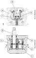
- Figs. 3A , 3B , 3C and 3D disclose a gear pump with a driving wheel (1) and a driven wheel (2) with helical toothing.
- the use of toothed wheels with helical toothing generates axial loads or stress (Fa, Pa) during operation.
- the generation of the axial stress (Fa, Pa) is caused by the projection of the transmission forces (Fa) and the pressure forces (Pa) acting on the sections of the toothed wheels along the axial direction.
- Fig. 3D shows the resultants (A, B) of all axial forces acting on the toothed wheels (1, 2), respectively.
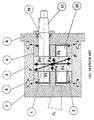
- axial forces (A, B) acting on the driving and driven toothed wheels (11, 12) of the pump are both directed towards the back lid (16) and opposed by hydraulic pistons (51, 52) disposed at the ends of the toothed wheels, which exert contrast forces (A', B').
- the hydraulic pistons (51, 52) are fed by means of passages (59, 60, 61) that connect the rear chambers (57 and 58) of the hydraulic pistons with the inlet area of the pump.
- the area of the hydraulic pistons (51, 52) must be suitably dimensioned in order to balance the axial forces (A, B).
- the axial forces (A, B) acting on the toothed wheels are generated by the contribution of two factors: the axial component of the pressure (Pa) ( Fig. 3B ) and the axial component of the force (Fa) generated by the torque transmission from the driving wheel to the driven wheel ( Fig. 3A ). Regardless of the direction of rotation and the direction of the helix used for the wheels, the forces (Pa and Fa) are always concordant on the driving wheel, whereas the forces (Pa and Fa) are always discordant on the driven wheel.
- A Pa + Fa N
- B Pa ⁇ Fa N
- the force Fa acts on the driving and driven wheel with the same intensity, but with opposite direction.
- the force Pa has the same intensity and the same direction on both toothed wheels. According to the most typical dimensioning of the toothed wheels, Pa > Fa and consequently the forces F1 and F2 always have a concordant direction.
- the use of the compensating pistons is a rather inexpensive and easy-to-make solution because the work operations and the parts are simple and reliable.
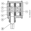
- the precepts disclosed by the patent US3658452 can solve the problem of balancing the axial forces only in case of monodirectional motors, in which the resultant forces A and B must be always directed towards the back lid (see Fig. 5 ), (i.e. in case of a right-hand pump with right-hand driving gear and left-hand driven gear, or in case of a left-hand pump with left-hand driving gear and right-hand driven gear).
- bidirectional pumps with two flow directions
- inverting the rotation of the driving shaft thus inverting the direction of the oil flow and the high and low pressure areas, inverting, for instance, the motion of hydraulic actuators.
- bidirectional motors is useful in the applications that require inverting the direction of the torque available at the outlet shaft of the hydraulic motor.
- Fig. 6A shows the distribution of the axial forces in case of a bidirectional pump, in an operating condition in which the axial forces A and B are directed towards the front flange.
- the solution disclosed in US3658452 is not applicable because the inversion of the motion and of the inlet side with the outlet side results in the inversion of the axial forces (A, B) acting on the toothed wheels (1, 2), as shown in Fig.6B .
- the axial forces (A, B) are directed towards the front flange (6) and not towards the back lid (7).
- Fig. 7 shows a multiple two-stage pump comprising a front stage (S A ) and a rear stage (S B ).
- S A front stage
- S B rear stage
- a multiple pump is necessary to connect multiple independent circuits to a single power take-off.
- the pumps are connected in parallel and the rear stage (S B ) receives the necessary torque by means of a mechanical connection (500) (such as Oldham coupling or splined coupling), from the shaft of the driving wheel of the front stage (S A ).
- a mechanical connection 500
- the precepts disclosed by the patent US3658452 are not applicable when the axial forces (A, B) are directed towards a side of the pump that is crossed by the shaft of a toothed wheel.
- the purpose of the present invention is to remedy the drawbacks of the prior art, by providing a hydraulic system to balance the axial forces in gear pumps or hydraulic motors with helical toothing of bidirectional or multiple stage type.
- the gear pump or motor of the invention comprises:
- the gear pump or motor of the invention also comprises:
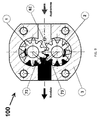
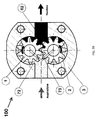
- a bi-directional gear pump according to the invention is disclosed, being generally referred to with numeral (100).
- the pump (100) comprises a first toothed wheel (1), a second toothed wheel (2), a back lid (7) in closing position and a front flange (6) from which a projecting portion (13) of the shaft protrudes frontally, being connected to the shaft (10) of the first toothed wheel (1).
- Both toothed wheels (1, 2) are provided with helical toothing.
- the projecting portion (13) of the shaft is connected to a motor (M) that can make a kinematic mechanism rotate in clockwise or anticlockwise direction.
- M motor
- the first toothed wheel (1) is the driving wheel
- the second toothed wheel (2) is the driven wheel.
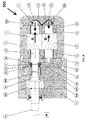
- Two ducts (72, 73) are obtained in the back lid (7), which put the outlet chamber (shown in bold in Fig. 9 ) of the pump in communication with the chambers (70, 71) of the two pistons (270, 271).
- the pistons (270, 271) push against the shafts (10, 20) of the toothed wheels, exercising forces (A', B') that balance the axial forces (A, B) acting on the toothed wheels.
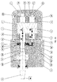
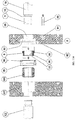
- An intermediate flange (8) is disposed between the case (3) and the front flange (6) in order to compensate said forces (A, B).
- said intermediate flange (8) is provided with a through hole (85) in order to allow for the passage of an end portion (T) of the shaft (10) of the toothed driving wheel.
- the intermediate flange (8) comprises a first chamber (80) with annular shape, obtained around the through hole (85) and a second chamber (81) with cylindrical shape, in axial position to the shaft (20) of the driven wheel (2).
- a duct (82) is obtained in the intermediate flange (82) that puts the two chambers (80, 81) in communication with the outlet duct of the pump (shown in bold in Fig. 10 ).
- a compensating ring (9) is provided in the first chamber (80).
- the compensating ring (9) is inserted on the end portion (T) of the shaft (10) of the driving wheel.
- a shoulder (15) is obtained in proximal position to the end portion (T) of the shaft of the driving wheel, against which the compensating ring (9) is stopped.
- the compensating ring (9) is splined on the end portion (T) of the shaft (10) to avoid undesired friction that may cause fluid leakage from the high-pressure area to the low-pressure area of the pump.
- the compensating ring (9) comprises a cylinder (90) and a collar (91) that radially protrudes outwards from the cylinder (90).
- the compensating ring (9) is internally empty and is provided with a through hole (92) to allow for the passage of the end portion (T) of the shaft of the driving wheel.
- the through hole (92) has a splined female section, whereas the end portion (T) of the shaft (10) has a splined male section.
- Two dynamic seals (95, 96) are disposed in the first chamber (80) of the intermediate flange (8) to support the compensating ring (9) in such way to eliminate possible leakage from the high-pressure areas to the low-pressure areas.
- a cylindrical piston (88) is disposed in the second chamber (81) of the intermediate flange.
- the chambers (81, 80) of the intermediate flange are in communication with the outlet duct (high pressure), and consequently the fluid pushes the compensating ring (9) and the piston (88) in the direction of the arrows (A', B') (see Fig. 11 ) in such manner to compensate the axial forces (A, B) exerted on the gears.
- the collar (91) of the compensating ring has an external diameter (d1) and the cylinder (90) of the compensating ring has an external diameter (d2).
- the annular area defined by the diameters d 1 and d 2 is such to completely compensate the axial force (A).
- the values of the diameters d 1 and d 2 are calculated with the formula (7) considering an annular section with equivalent area instead of a circular area.
- the piston (88) has an external diameter (d3).
- the dimension (d 3 ) of the piston (88) is such to completely compensate the axial force (B).
- the axial forces are balanced both on the shaft of the toothed driving wheel (1) and on the shaft of the toothed driven wheel (2), respectively by means of the compensating ring (9) and the piston (88).
- the resultant (A) of the axial thrusts on the shaft of the driving wheel (1) is much higher than the resultant (B) of the axial thrusts on the shaft of the driven wheel (2). Therefore the piston (88) is optional and may be omitted.
- the end portion (T) of the shaft of the driving wheel externally protrudes from the intermediate flange (8) and is connected by means of a mechanical connection (500) to a drive shaft (12) provided with said projecting portion (13) connected to the motor (M).
- the mechanical connection (500) can be a splined coupling, an Oldham coupling or a coupling of any other type.
- the mechanical connection (500) is housed in a plate (501) that is stopped against the intermediate flange (8).
- An intermediate plate (600) whereon bearings (601) that revolvingly support the shaft (12) can be optionally provided.
- the intermediate plate (600) is disposed between the front flange (6) and the plate (501) that houses the mechanical connection (500).
- Figs. 8 to 11 refer to a pump
- said figures may also refer to a hydraulic motor wherein the pump outlet (high-pressure area) corresponds to the inlet of the motor fluid and the pump inlet (low-pressure area) corresponds to the discharge of the motor fluid.
- the pump outlet high-pressure area
- the pump inlet low-pressure area
- the projecting portion of the shaft (13) is adapted to be connected to a load, not to a motor (M)
- Figs. 12 , 13 illustrate a multiple gear pump (200).
- the multiple gear pump (200) comprises a front stage (S A ) and a rear stage (S B ). Each stage comprises toothed wheels with helical toothing.
- the rear stage (S B ) is the last stage of the pump and therefore is closed with the back lid (7), from which no shaft protrudes.
- the end portion (T) of the shaft of the driving toothed wheel of the front stage (S A ) is connected to the end portion (T) of the shaft of the toothed driving wheel of the rear stage (S B ) by means of the mechanical connection (500) housed in the plate (501) disposed between the two stages (S A , S B ).
- the toothed wheels of the front stage and of the rear stage are subject to respective axial forces (A, B, C, D), which are all directed towards the back lid (7).
- the axial forces (A, B) on the toothed wheels of the front stage (S A ) are balanced by the action of the compensating ring (9) and of the piston (88) disposed in the intermediate flange (8).
- the compensating ring (9) and the piston (88) generate respective axial forces (A', B') that compensate the axial forces (A, B) exerted on the toothed wheels (1, 2) of the front stage (S A ).
- the plate (501) that houses the mechanical connection (500) is disposed between the intermediate flange (8) and the rear stage (S B ).
- the multiple gear pump (200) may comprise one or more intermediate stages (S I ) disposed between the front stage (S A ) and the rear stage (S B ).
- Each intermediate stage (S I ) comprises a first toothed wheel (1) and a second toothed wheel (2) with helical toothing.
- the first toothed wheel (1) of the intermediate stage (S I ) receives the motion from the end portion (T) of the shaft of the driving wheel (1) of the frontally positioned stage (S A ) and in turn gives motion to a posterior stage (S B ) by means of the mechanical connection (500) that connects the shaft of the first toothed wheel of the intermediate stage to the shaft of the first toothed wheel of the posterior stage (S B ).
- an additional intermediate flange (8) is disposed between the case of the intermediate stage (S I ) and the mechanical connection (500).
- the compensating ring (9) of the intermediate flange (8) compensates the axial thrust (A) of the first toothed wheel (1) of the intermediate stage (S I ).
Landscapes
- Engineering & Computer Science (AREA)
- Mechanical Engineering (AREA)
- General Engineering & Computer Science (AREA)
- Physics & Mathematics (AREA)
- Fluid Mechanics (AREA)
- Rotary Pumps (AREA)
- Details And Applications Of Rotary Liquid Pumps (AREA)
- Hydraulic Motors (AREA)
- Gears, Cams (AREA)
- Gear Transmission (AREA)
Claims (11)
- Pompe à engrenages ou moteur hydraulique à pignons (100; 200) comprenant :- une première roue dentée (1) solidaire à un arbre (10),- une seconde roue dentée (2) solidaire à un arbre (20) et qui s'embraye avec la première roue dentée (1),- des supports (4, 5) qui supportent de manière pivotante les arbres (10, 20) des roues dentées,- un cadre (3) qui contient les supports (4, 5) et définit un conduit d'entrée et un conduit de sortie d'un fluide,- un étrier avant (6) duquel fait saillie en avant une portion débordante (13) d'arbre reliée à l'arbre (10) de la première roue dentée, ladite portion débordante (13) d'arbre étant destinée à être reliée à un moteur (M) ou à une charge, et- un carter arrière (7) fixé au cadre (3),
où- la denture des dites roues dentées (1, 2) est du type hélicoïdal,caractérisée en ce qu'elle comprend :- un étrier intermède (8) disposé entre ledit cadre (3) et ledit étrier avant (6), ledit étrier intermède (8) comprenant une première chambre (80) reliée moyennant un conduit de connexion (82) au conduit d'entrée ou de sortie du fluide ;- une cale d'entretoise (9) montée dans ladite première chambre (80) de l'étrier intermède et caletée sur une portion (T) du dit arbre (10) de la première roue dentée, de manière à compenser les forces axiales (A) auxquelles est assujettie la première roue dentée et permettre la transmission du mouvement sur l'arbre (10) de la première roue dentée,où ladite cale d'entretoise (9) comprend un cylindre (90) creux à l'intérieur et un collier (91) qui fait saillie radialement du cylindre (90), où les diamètres extérieurs (d1, d2) du cylindre (90) et du collier (91) sont sélectionnés de façon à compenser les forces axiales (A) auxquelles est assujettie la première roue dentée. - Pompe à engrenages ou moteur hydraulique à pignons (100; 200) selon la revendication 1, comprenant également :- une seconde chambre (81) réalisée dans ledit étrier intermède (8) et reliée moyennant ledit conduit de connexion (82) au conduit d'entrée ou de sortie du fluide de la pompe- un piston (88) monté dans ladite seconde chambre (81) du dit étrier intermède pour aller en butée contre une extrémité du dit arbre (20) de la seconde roue dentée, de façon à compenser les forces axiales (B) agissant sur ladite seconde roue dentée.
- Pompe à engrenages ou moteur hydraulique à pignons (100; 200) selon la revendication 1, où ladite portion (T) de l'arbre de la première roue dentée sur lequel est caletée ladite cale d'entretoise (9) est une portion terminale (T) et la pompe à engrenages comprend également une connexion mécanique (500) qui relie ladite portion terminale (T) de l'arbre de la roue dentée menante à un autre arbre (13; 10) pour la transmission du mouvement.
- Pompe à engrenages ou moteur hydraulique à pignons (100; 200) selon la revendication 1 ou 2, où la cale d'entretoise (9) est caletée sur ladite portion (T) de l'arbre de la roue menante, de façon à éliminer les éventuels frottements connexes.
- Pompe à engrenages ou moteur hydraulique à pignons (100; 200) selon l'une quelconque des revendications précédentes, comprenant des étanchéités dynamiques (95, 96) disposées dans ladite première chambre (80) de l'étrier intermède (8) pour supporter ladite cale d'entretoise (9), de sorte à éliminer toutes fuites depuis les zones haute pression vers celles basse pression.
- Pompe à engrenages ou moteur hydraulique à pignons (100; 200) selon l'une quelconque des revendications précédentes, où ledit carter de fermeture (7) comprend :- une première chambre (70) et une seconde chambre (71) reliées moyennant des conduits (72, 73) au conduit d'entrée ou de sortie du fluide ;- un premier piston (270) monté dans ladite première chambre (70) du carter de fermeture pour aller en butée contre l'extrémité de l'arbre (10) de la première roue dentée (1), de manière à compenser les forces axiales (A; C) auxquelles est assujettie la première roue dentée, et- un second piston (271) monté dans ladite seconde chambre (71) du carter de fermeture pour aller en butée contre l'extrémité de l'arbre (20) de la seconde roue dentée (2), de manière à compenser les forces axiales (B; D) auxquelles est assujettie la seconde roue dentée.
- Pompe à engrenages ou moteur hydraulique à pignons (100; 200) selon l'une quelconque des revendications précédentes, comprenant également une connexion mécanique (500) qui relie l'arbre de la première roue dentée (1) à un arbre de sortie (12) qui comprend ladite partie débordante (13) qui fait saillie depuis l'étrier avant (6).
- Pompe à engrenages (100) selon l'une quelconque des revendications précédentes, où ladite partie débordante (13) de l'arbre est reliée à un moteur (M) de façon que la première roue dentée (1) est une roue menante et la seconde roue dentée (2) est une roue menée.
- Moteur hydraulique à pignons (200) selon l'une quelconque des revendications de 1 à 7, où ladite partie débordante (13) de l'arbre est reliée à une charge.
- Pompe à engrenages ou moteur hydraulique à pignons (200) selon l'une quelconque des revendications de 1 à 7, où ladite pompe à engrenages ou moteur hydraulique à pignons est du type multiple et comprend :- au moins un stade avant (SA) comprenant une première roue dentée (1) et une seconde roue dentée (2),- un stade arrière (SB) comprenant une première roue dentée (1) et une seconde roue dentée (2) et ledit carter de fermeture (7), et- une connexion mécanique (500) qui relie l'arbre de la première roue dentée (1) du stade avant (SA) à l'arbre de la première roue dentée (1) du stade arrière (SB),où ledit étrier intermède (8) est disposé entre le cadre (3) du stade avant (SA) et la connexion mécanique (500) et ladite cale d'entretoise (9) de l'étrier intermède compense la poussée axiale (A) de la première roue dentée (1, 2) du stade avant (SA);
- Pompe à engrenages ou moteur hydraulique à pignons (200) selon la revendication 10, comprenant également au moins un stade intermède (SI) positionné entre le stade avant (SA) et le stade arrière (SB), chaque stade intermède (SI) comprenant une première roue dentée (1) et une seconde roue dentée (2) ayant denture hélicoïdale, la première roue dentée (1) du stade intermède (SI) prend le mouvement depuis le segment terminal (T) de l'arbre de la roue menante (1) du stade positionné en avant (SA), et déplace un stade positionné à l'arrière (SB), par le biais d'une connexion mécanique (500) qui relie l'arbre de la première roue dentée du stade intermède (SI) à l'arbre de la première roue dentée du stade positionné à l'arrière (SB), où ledit étrier intermède (8) supplémentaire est disposé entre le cadre du stade intermède (SI) et la connexion mécanique (500), ledit étrier intermède (8) supplémentaire comprenant une cale d'entretoise (9) qui compense la poussée axiale (A) de la première roue dentée (1) du stade intermède (SI).
Applications Claiming Priority (2)
| Application Number | Priority Date | Filing Date | Title |
|---|---|---|---|
| IT000102A ITAN20130102A1 (it) | 2013-05-30 | 2013-05-30 | Pompa o motore idraulico ad ingranaggi a dentatura elicoidale con sistema idraulico per il bilanciamento di forze assiali. |
| PCT/EP2014/060297 WO2014191253A1 (fr) | 2013-05-30 | 2014-05-20 | Pompe à engrenages ou moteur hydraulique à engrenages comprenant une denture hélicoïdale dotée d'un système hydraulique pour l'équilibrage de la poussée axiale |
Publications (2)
| Publication Number | Publication Date |
|---|---|
| EP2859237A1 EP2859237A1 (fr) | 2015-04-15 |
| EP2859237B1 true EP2859237B1 (fr) | 2016-05-04 |
Family
ID=48951480
Family Applications (1)
| Application Number | Title | Priority Date | Filing Date |
|---|---|---|---|
| EP14728475.6A Active EP2859237B1 (fr) | 2013-05-30 | 2014-05-20 | Pompe à engrenages ou moteur hydraulique à engrenages comprenant une denture hélicoïdale dotée d'un système hydraulique pour l'équilibrage de la poussée axiale |
Country Status (15)
| Country | Link |
|---|---|
| US (1) | US9567999B2 (fr) |
| EP (1) | EP2859237B1 (fr) |
| JP (1) | JP6074826B2 (fr) |
| KR (1) | KR101664646B1 (fr) |
| CN (1) | CN104379934B (fr) |
| AU (1) | AU2014259589B2 (fr) |
| BR (1) | BR112014030180B1 (fr) |
| DK (1) | DK2859237T3 (fr) |
| ES (1) | ES2586413T3 (fr) |
| IN (1) | IN2014MN02509A (fr) |
| IT (1) | ITAN20130102A1 (fr) |
| PL (1) | PL2859237T3 (fr) |
| RU (1) | RU2598751C2 (fr) |
| TW (1) | TWI621778B (fr) |
| WO (1) | WO2014191253A1 (fr) |
Cited By (1)
| Publication number | Priority date | Publication date | Assignee | Title |
|---|---|---|---|---|
| CN110345065A (zh) * | 2018-04-05 | 2019-10-18 | 凯斯帕公司 | 泵送装置 |
Families Citing this family (21)
| Publication number | Priority date | Publication date | Assignee | Title |
|---|---|---|---|---|
| KR101715677B1 (ko) | 2015-09-17 | 2017-03-15 | (유)한독엘리베이터 | 유압기어펌프 |
| CN105805528A (zh) * | 2016-03-16 | 2016-07-27 | 哈尔滨宏万智科技开发有限公司 | 一种具有双传动齿轮轴的齿轮油泵 |
| IT201600076227A1 (it) * | 2016-07-20 | 2018-01-20 | Settima Meccanica S R L Soc A Socio Unico | Ruota dentata bi-elicoidale con angolo d’elica variabile e con profilo del dente non incapsulante per apparecchiature idrauliche ad ingranaggi |
| US10808694B2 (en) * | 2016-08-15 | 2020-10-20 | Georgia Tech Research Corporation | Systems and devices for pumping and controlling high temperature fluids |
| JP6376197B2 (ja) * | 2016-09-30 | 2018-08-22 | ダイキン工業株式会社 | 歯車ポンプ又は歯車モータ |
| US10000895B2 (en) * | 2016-10-06 | 2018-06-19 | Caterpillar Inc. | Rotating hydraulic gear motor |
| CN106438680A (zh) * | 2016-11-24 | 2017-02-22 | 北京航科发动机控制系统科技有限公司 | 一种带密封结构的高压齿轮泵轴承 |
| CZ307543B6 (cs) * | 2017-06-08 | 2018-11-21 | Emil Brabec | Pístové čerpadlo pro kapaliny, zvláště pro viskóznější a pastovitá média |
| CN108223361A (zh) * | 2017-08-08 | 2018-06-29 | 河南航天液压气动技术有限公司 | 一种电动燃油泵 |
| DE102017218287B4 (de) * | 2017-10-12 | 2021-12-23 | Vitesco Technologies GmbH | Kraftstoffpumpe und Kraftstofffördereinheit |
| CN108571445B (zh) * | 2018-04-16 | 2019-08-13 | 宁波布赫懋鑫液压技术有限公司 | 一种具有轴向补偿功能的内啮合齿轮泵 |
| IT201800005956A1 (it) * | 2018-06-01 | 2019-12-01 | Macchina volumetrica ad ingranaggi con denti elicoidali | |
| US11060559B2 (en) * | 2018-06-11 | 2021-07-13 | Eaton Intelligent Power Limited | Bi-metallic journal bearing with additive manufactured sleeve |
| KR20200036183A (ko) | 2018-09-28 | 2020-04-07 | 신진정밀(주) | 축방향 스러스트 밸런싱 기능을 갖는 헬리컬 기어 펌프 |
| CN110617213B (zh) * | 2019-10-24 | 2021-06-04 | 山东大学 | 轴端动静压浮动支承的螺旋齿双圆弧齿形液压齿轮泵 |
| RU195531U1 (ru) * | 2019-11-18 | 2020-01-30 | Акционерное общество "Ярославский завод дизельной аппаратуры" | Топливоподкачивающий насос |
| CN111622946B (zh) * | 2020-06-02 | 2022-02-01 | 安徽优源液压科技有限公司 | 一种大功率齿轮油泵 |
| RU206547U1 (ru) * | 2021-06-21 | 2021-09-15 | Сергей Иванович Никитин | Шестеренный насос |
| RU210280U1 (ru) * | 2021-12-20 | 2022-04-05 | Сергей Иванович Никитин | Шестеренный насос |
| US12025131B2 (en) | 2022-08-08 | 2024-07-02 | Deere & Company | Torque transfer gear pump |
| DE102022133597A1 (de) | 2022-12-16 | 2024-06-27 | Klaus Lübke | Zahnradpumpe |
Family Cites Families (17)
| Publication number | Priority date | Publication date | Assignee | Title |
|---|---|---|---|---|
| US2159744A (en) * | 1936-08-26 | 1939-05-23 | Brown & Sharpe Mfg | Gear pump |
| US2462924A (en) * | 1944-03-01 | 1949-03-01 | Equi Flow Inc | Gear tooth profile |
| US3164099A (en) * | 1961-08-09 | 1965-01-05 | Iyoi Hitosi | Toothed profiles of rotors of gear pump |
| US3104616A (en) * | 1961-08-14 | 1963-09-24 | Clark Equipment Co | Pressure loaded gear pump |
| US3658452A (en) * | 1969-11-18 | 1972-04-25 | Shimadzu Corp | Gear pump or motor |
| US4245969A (en) * | 1979-01-26 | 1981-01-20 | The Garrett Corporation | Pump |
| DE169307T1 (de) * | 1984-05-18 | 1986-07-24 | Nordson Corp., Amherst, Ohio | Pumpe fuer heissschmelzklebstoffe mit durchlaesse aufweisenden zahnraedern. |
| SE463682B (sv) * | 1984-06-20 | 1991-01-07 | Imo Ab | Hydraulisk skruvmaskin, foeretraedesvis utnyttjad som pump avsedd att nedsaenkas i ett borrhaal |
| SU1629609A1 (ru) * | 1989-03-30 | 1991-02-23 | Челябинский Политехнический Институт Им.Ленинского Комсомола | Регулируемый шестеренный насос |
| JPH0641755B2 (ja) * | 1989-04-19 | 1994-06-01 | 日機装株式会社 | キャンド内接ギヤポンプ |
| JP2512443Y2 (ja) | 1989-07-28 | 1996-10-02 | 帝人株式会社 | 溶融樹脂用ギアポンプ |
| US6887055B2 (en) * | 2002-10-25 | 2005-05-03 | Mario Antonio Morselli | Positive-displacement rotary pump |
| US20060039815A1 (en) * | 2004-08-18 | 2006-02-23 | Allan Chertok | Fluid displacement pump |
| US7300265B2 (en) * | 2005-09-12 | 2007-11-27 | Emerson Climate Technologies, Inc. | Flanged sleeve guide |
| US20070098586A1 (en) * | 2005-10-28 | 2007-05-03 | Autotronic Controls Corporation | Fuel pump |
| IT1390747B1 (it) * | 2008-08-12 | 2011-09-23 | Settima Flow Mechanisms Srl | Pompa volumetrica rotativa ad ingranaggi |
| DE102009012853A1 (de) * | 2009-03-12 | 2010-09-16 | Robert Bosch Gmbh | Hydraulische Zahnradmaschine |
-
2013
- 2013-05-30 IT IT000102A patent/ITAN20130102A1/it unknown
-
2014
- 2014-05-16 TW TW103117281A patent/TWI621778B/zh active
- 2014-05-20 KR KR1020147032370A patent/KR101664646B1/ko active Active
- 2014-05-20 EP EP14728475.6A patent/EP2859237B1/fr active Active
- 2014-05-20 BR BR112014030180-8A patent/BR112014030180B1/pt active IP Right Grant
- 2014-05-20 PL PL14728475.6T patent/PL2859237T3/pl unknown
- 2014-05-20 AU AU2014259589A patent/AU2014259589B2/en active Active
- 2014-05-20 CN CN201480001562.6A patent/CN104379934B/zh active Active
- 2014-05-20 US US14/401,465 patent/US9567999B2/en active Active
- 2014-05-20 JP JP2015546067A patent/JP6074826B2/ja active Active
- 2014-05-20 DK DK14728475.6T patent/DK2859237T3/en active
- 2014-05-20 RU RU2015102102/06A patent/RU2598751C2/ru active
- 2014-05-20 WO PCT/EP2014/060297 patent/WO2014191253A1/fr not_active Ceased
- 2014-05-20 IN IN2509MUN2014 patent/IN2014MN02509A/en unknown
- 2014-05-20 ES ES14728475.6T patent/ES2586413T3/es active Active
Cited By (1)
| Publication number | Priority date | Publication date | Assignee | Title |
|---|---|---|---|---|
| CN110345065A (zh) * | 2018-04-05 | 2019-10-18 | 凯斯帕公司 | 泵送装置 |
Also Published As
| Publication number | Publication date |
|---|---|
| TW201512541A (zh) | 2015-04-01 |
| ITAN20130102A1 (it) | 2014-12-01 |
| US20160265528A1 (en) | 2016-09-15 |
| TWI621778B (zh) | 2018-04-21 |
| KR101664646B1 (ko) | 2016-10-11 |
| US9567999B2 (en) | 2017-02-14 |
| BR112014030180B1 (pt) | 2021-12-21 |
| AU2014259589B2 (en) | 2015-12-10 |
| JP2016507686A (ja) | 2016-03-10 |
| PL2859237T3 (pl) | 2016-11-30 |
| JP6074826B2 (ja) | 2017-02-08 |
| DK2859237T3 (en) | 2016-08-15 |
| IN2014MN02509A (fr) | 2015-07-17 |
| RU2015102102A (ru) | 2016-08-10 |
| BR112014030180A2 (pt) | 2017-06-27 |
| AU2014259589A1 (en) | 2015-01-15 |
| CN104379934B (zh) | 2016-08-31 |
| RU2598751C2 (ru) | 2016-09-27 |
| CN104379934A (zh) | 2015-02-25 |
| HK1208717A1 (zh) | 2016-03-11 |
| EP2859237A1 (fr) | 2015-04-15 |
| ES2586413T3 (es) | 2016-10-14 |
| KR20150009973A (ko) | 2015-01-27 |
| WO2014191253A1 (fr) | 2014-12-04 |
Similar Documents
| Publication | Publication Date | Title |
|---|---|---|
| US9567999B2 (en) | Gear pump or hydraulic gear motor with helical toothing provided with hydraulic system for axial thrust balance | |
| CN109416107B (zh) | 用于机动车的变速器以及用于机动车的动力传动系 | |
| US8104375B2 (en) | Differential gear unit for motor vehicles comprising an active control mechanism for the driving force distribution | |
| US10487657B2 (en) | Hydraulic machine | |
| KR101289498B1 (ko) | 차동 기어 메커니즘 및 이를 위한 개선된 액슬 리텐션 장치 | |
| CN1892071B (zh) | 不依赖于速度差的改进的联接装置 | |
| JPH07305685A (ja) | 回転歯車装置 | |
| JP6086979B2 (ja) | ギヤポンプ | |
| US8596165B2 (en) | Multiple gear motor drive | |
| HK1208717B (en) | Gear pump or hydraulic gear motor with helical toothing provided with hydraulic system for axial thrust balance | |
| KR102519195B1 (ko) | 자동차용 슬립 제한형 차동 장치 및 이를 포함하는 전동 구동 장치 | |
| KR102519194B1 (ko) | 자동차용 슬립 제한형 차동 장치 및 이를 포함하는 전동 구동 장치 | |
| EP3936725B1 (fr) | Moteur ou pompe à engrenages hélicoïdaux | |
| US20240124049A1 (en) | Steering Transmission for Electromechanical Steering System for a Vehicle and Electromechanical Steering System for a Vehicle | |
| WO2000061947A1 (fr) | Pompe hydraulique a double voie | |
| WO2014123490A2 (fr) | Moteur à engrenages hydraulique, pompe à engrenages et boîte de vitesses à paramètres variables en continu | |
| US11248602B2 (en) | Fluid delivery device with a forepump, a main pump, and bypass line with a check valve | |
| KR20260032897A (ko) | 축방향 힘의 균형을 위해 양방향 유압 시스템이 제공되는 나선형 톱니 기어를 갖는 가역 유압 기계 | |
| US6524087B1 (en) | Hydrostatic planetary rotation machine having an orbiting rotary valve | |
| EP2034184A2 (fr) | Appareil de pompage | |
| WO1997012124A1 (fr) | Machine hydraulique a anneau dente divise radiallement en une partie interne a premiere denture interne et une partie externe a seconde denture externe, en rotation l'une par rapport a l'autre | |
| CN112449621A (zh) | 用于车辆的静压驱动系统 | |
| WO2018098539A1 (fr) | Système de moteur/pompe à cylindrée variable concentrique linéaire | |
| WO2017091099A1 (fr) | Transmission hydraulique pour automobile | |
| HK1211646B (en) | Hydraulic gear motor, gear pump and gearbox with continuously variable parameters |
Legal Events
| Date | Code | Title | Description |
|---|---|---|---|
| PUAI | Public reference made under article 153(3) epc to a published international application that has entered the european phase |
Free format text: ORIGINAL CODE: 0009012 |
|
| 17P | Request for examination filed |
Effective date: 20150109 |
|
| AK | Designated contracting states |
Kind code of ref document: A1 Designated state(s): AL AT BE BG CH CY CZ DE DK EE ES FI FR GB GR HR HU IE IS IT LI LT LU LV MC MK MT NL NO PL PT RO RS SE SI SK SM TR |
|
| AX | Request for extension of the european patent |
Extension state: BA ME |
|
| GRAP | Despatch of communication of intention to grant a patent |
Free format text: ORIGINAL CODE: EPIDOSNIGR1 |
|
| DAX | Request for extension of the european patent (deleted) | ||
| INTG | Intention to grant announced |
Effective date: 20160122 |
|
| REG | Reference to a national code |
Ref country code: HK Ref legal event code: DE Ref document number: 1208717 Country of ref document: HK |
|
| GRAS | Grant fee paid |
Free format text: ORIGINAL CODE: EPIDOSNIGR3 |
|
| GRAA | (expected) grant |
Free format text: ORIGINAL CODE: 0009210 |
|
| AK | Designated contracting states |
Kind code of ref document: B1 Designated state(s): AL AT BE BG CH CY CZ DE DK EE ES FI FR GB GR HR HU IE IS IT LI LT LU LV MC MK MT NL NO PL PT RO RS SE SI SK SM TR |
|
| REG | Reference to a national code |
Ref country code: GB Ref legal event code: FG4D |
|
| REG | Reference to a national code |
Ref country code: CH Ref legal event code: EP |
|
| REG | Reference to a national code |
Ref country code: AT Ref legal event code: REF Ref document number: 797157 Country of ref document: AT Kind code of ref document: T Effective date: 20160515 |
|
| REG | Reference to a national code |
Ref country code: FR Ref legal event code: PLFP Year of fee payment: 3 |
|
| REG | Reference to a national code |
Ref country code: IE Ref legal event code: FG4D |
|
| REG | Reference to a national code |
Ref country code: DE Ref legal event code: R096 Ref document number: 602014001824 Country of ref document: DE |
|
| REG | Reference to a national code |
Ref country code: RO Ref legal event code: EPE |
|
| REG | Reference to a national code |
Ref country code: DK Ref legal event code: T3 Effective date: 20160802 |
|
| REG | Reference to a national code |
Ref country code: SE Ref legal event code: TRGR |
|
| REG | Reference to a national code |
Ref country code: NL Ref legal event code: FP |
|
| REG | Reference to a national code |
Ref country code: LT Ref legal event code: MG4D |
|
| REG | Reference to a national code |
Ref country code: CH Ref legal event code: NV Representative=s name: OFFICE ERNEST T. FREYLINGER S.A., CH |
|
| REG | Reference to a national code |
Ref country code: NO Ref legal event code: T2 Effective date: 20160504 |
|
| REG | Reference to a national code |
Ref country code: ES Ref legal event code: FG2A Ref document number: 2586413 Country of ref document: ES Kind code of ref document: T3 Effective date: 20161014 |
|
| PG25 | Lapsed in a contracting state [announced via postgrant information from national office to epo] |
Ref country code: LT Free format text: LAPSE BECAUSE OF FAILURE TO SUBMIT A TRANSLATION OF THE DESCRIPTION OR TO PAY THE FEE WITHIN THE PRESCRIBED TIME-LIMIT Effective date: 20160504 Ref country code: FI Free format text: LAPSE BECAUSE OF FAILURE TO SUBMIT A TRANSLATION OF THE DESCRIPTION OR TO PAY THE FEE WITHIN THE PRESCRIBED TIME-LIMIT Effective date: 20160504 |
|
| PG25 | Lapsed in a contracting state [announced via postgrant information from national office to epo] |
Ref country code: RS Free format text: LAPSE BECAUSE OF FAILURE TO SUBMIT A TRANSLATION OF THE DESCRIPTION OR TO PAY THE FEE WITHIN THE PRESCRIBED TIME-LIMIT Effective date: 20160504 Ref country code: HR Free format text: LAPSE BECAUSE OF FAILURE TO SUBMIT A TRANSLATION OF THE DESCRIPTION OR TO PAY THE FEE WITHIN THE PRESCRIBED TIME-LIMIT Effective date: 20160504 Ref country code: PT Free format text: LAPSE BECAUSE OF FAILURE TO SUBMIT A TRANSLATION OF THE DESCRIPTION OR TO PAY THE FEE WITHIN THE PRESCRIBED TIME-LIMIT Effective date: 20160905 Ref country code: GR Free format text: LAPSE BECAUSE OF FAILURE TO SUBMIT A TRANSLATION OF THE DESCRIPTION OR TO PAY THE FEE WITHIN THE PRESCRIBED TIME-LIMIT Effective date: 20160805 Ref country code: LV Free format text: LAPSE BECAUSE OF FAILURE TO SUBMIT A TRANSLATION OF THE DESCRIPTION OR TO PAY THE FEE WITHIN THE PRESCRIBED TIME-LIMIT Effective date: 20160504 |
|
| PG25 | Lapsed in a contracting state [announced via postgrant information from national office to epo] |
Ref country code: SK Free format text: LAPSE BECAUSE OF FAILURE TO SUBMIT A TRANSLATION OF THE DESCRIPTION OR TO PAY THE FEE WITHIN THE PRESCRIBED TIME-LIMIT Effective date: 20160504 Ref country code: EE Free format text: LAPSE BECAUSE OF FAILURE TO SUBMIT A TRANSLATION OF THE DESCRIPTION OR TO PAY THE FEE WITHIN THE PRESCRIBED TIME-LIMIT Effective date: 20160504 |
|
| REG | Reference to a national code |
Ref country code: DE Ref legal event code: R097 Ref document number: 602014001824 Country of ref document: DE |
|
| PG25 | Lapsed in a contracting state [announced via postgrant information from national office to epo] |
Ref country code: SM Free format text: LAPSE BECAUSE OF FAILURE TO SUBMIT A TRANSLATION OF THE DESCRIPTION OR TO PAY THE FEE WITHIN THE PRESCRIBED TIME-LIMIT Effective date: 20160504 |
|
| PLBE | No opposition filed within time limit |
Free format text: ORIGINAL CODE: 0009261 |
|
| STAA | Information on the status of an ep patent application or granted ep patent |
Free format text: STATUS: NO OPPOSITION FILED WITHIN TIME LIMIT |
|
| 26N | No opposition filed |
Effective date: 20170207 |
|
| REG | Reference to a national code |
Ref country code: FR Ref legal event code: PLFP Year of fee payment: 4 |
|
| PG25 | Lapsed in a contracting state [announced via postgrant information from national office to epo] |
Ref country code: SI Free format text: LAPSE BECAUSE OF FAILURE TO SUBMIT A TRANSLATION OF THE DESCRIPTION OR TO PAY THE FEE WITHIN THE PRESCRIBED TIME-LIMIT Effective date: 20160504 |
|
| REG | Reference to a national code |
Ref country code: HK Ref legal event code: GR Ref document number: 1208717 Country of ref document: HK |
|
| REG | Reference to a national code |
Ref country code: FR Ref legal event code: PLFP Year of fee payment: 5 |
|
| PG25 | Lapsed in a contracting state [announced via postgrant information from national office to epo] |
Ref country code: HU Free format text: LAPSE BECAUSE OF FAILURE TO SUBMIT A TRANSLATION OF THE DESCRIPTION OR TO PAY THE FEE WITHIN THE PRESCRIBED TIME-LIMIT; INVALID AB INITIO Effective date: 20140520 |
|
| PG25 | Lapsed in a contracting state [announced via postgrant information from national office to epo] |
Ref country code: MT Free format text: LAPSE BECAUSE OF NON-PAYMENT OF DUE FEES Effective date: 20160531 Ref country code: CY Free format text: LAPSE BECAUSE OF FAILURE TO SUBMIT A TRANSLATION OF THE DESCRIPTION OR TO PAY THE FEE WITHIN THE PRESCRIBED TIME-LIMIT Effective date: 20160504 Ref country code: MK Free format text: LAPSE BECAUSE OF FAILURE TO SUBMIT A TRANSLATION OF THE DESCRIPTION OR TO PAY THE FEE WITHIN THE PRESCRIBED TIME-LIMIT Effective date: 20160504 Ref country code: IS Free format text: LAPSE BECAUSE OF FAILURE TO SUBMIT A TRANSLATION OF THE DESCRIPTION OR TO PAY THE FEE WITHIN THE PRESCRIBED TIME-LIMIT Effective date: 20160504 |
|
| PG25 | Lapsed in a contracting state [announced via postgrant information from national office to epo] |
Ref country code: AL Free format text: LAPSE BECAUSE OF FAILURE TO SUBMIT A TRANSLATION OF THE DESCRIPTION OR TO PAY THE FEE WITHIN THE PRESCRIBED TIME-LIMIT Effective date: 20160504 |
|
| REG | Reference to a national code |
Ref country code: AT Ref legal event code: UEP Ref document number: 797157 Country of ref document: AT Kind code of ref document: T Effective date: 20160504 |
|
| REG | Reference to a national code |
Ref country code: DE Ref legal event code: R081 Ref document number: 602014001824 Country of ref document: DE Owner name: MARZOCCHI POMPE S.P.A., IT Free format text: FORMER OWNER: MARZOCCHI POMPE S.P.A., CASALECCHIO DI RENO, IT |
|
| REG | Reference to a national code |
Ref country code: LU Ref legal event code: HC Owner name: MARZOCCHI POMPE S.P.A.; IT Free format text: FORMER OWNER: MARZOCCHI POMPE S.P.A. Effective date: 20211012 |
|
| REG | Reference to a national code |
Ref country code: NO Ref legal event code: CHAD Owner name: MARZOCCHI POMPE S.P.A., IT |
|
| P01 | Opt-out of the competence of the unified patent court (upc) registered |
Effective date: 20230510 |
|
| PGFP | Annual fee paid to national office [announced via postgrant information from national office to epo] |
Ref country code: NL Payment date: 20250526 Year of fee payment: 12 |
|
| PGFP | Annual fee paid to national office [announced via postgrant information from national office to epo] |
Ref country code: MC Payment date: 20250526 Year of fee payment: 12 |
|
| PGFP | Annual fee paid to national office [announced via postgrant information from national office to epo] |
Ref country code: PL Payment date: 20250507 Year of fee payment: 12 Ref country code: DE Payment date: 20250528 Year of fee payment: 12 |
|
| PGFP | Annual fee paid to national office [announced via postgrant information from national office to epo] |
Ref country code: ES Payment date: 20250612 Year of fee payment: 12 Ref country code: GB Payment date: 20250520 Year of fee payment: 12 Ref country code: DK Payment date: 20250526 Year of fee payment: 12 |
|
| PGFP | Annual fee paid to national office [announced via postgrant information from national office to epo] |
Ref country code: NO Payment date: 20250520 Year of fee payment: 12 |
|
| PGFP | Annual fee paid to national office [announced via postgrant information from national office to epo] |
Ref country code: LU Payment date: 20250526 Year of fee payment: 12 Ref country code: BE Payment date: 20250526 Year of fee payment: 12 Ref country code: IT Payment date: 20250505 Year of fee payment: 12 |
|
| PGFP | Annual fee paid to national office [announced via postgrant information from national office to epo] |
Ref country code: FR Payment date: 20250526 Year of fee payment: 12 |
|
| PGFP | Annual fee paid to national office [announced via postgrant information from national office to epo] |
Ref country code: BG Payment date: 20250527 Year of fee payment: 12 |
|
| PGFP | Annual fee paid to national office [announced via postgrant information from national office to epo] |
Ref country code: CH Payment date: 20250601 Year of fee payment: 12 |
|
| PGFP | Annual fee paid to national office [announced via postgrant information from national office to epo] |
Ref country code: AT Payment date: 20250520 Year of fee payment: 12 Ref country code: RO Payment date: 20250512 Year of fee payment: 12 |
|
| PGFP | Annual fee paid to national office [announced via postgrant information from national office to epo] |
Ref country code: TR Payment date: 20250506 Year of fee payment: 12 |
|
| PGFP | Annual fee paid to national office [announced via postgrant information from national office to epo] |
Ref country code: CZ Payment date: 20250513 Year of fee payment: 12 |
|
| PGFP | Annual fee paid to national office [announced via postgrant information from national office to epo] |
Ref country code: IE Payment date: 20250520 Year of fee payment: 12 |
|
| PGFP | Annual fee paid to national office [announced via postgrant information from national office to epo] |
Ref country code: SE Payment date: 20250526 Year of fee payment: 12 |