EP2859629B1 - Agencement de réservoir sous pression avec une section de compensation de longueur variable - Google Patents
Agencement de réservoir sous pression avec une section de compensation de longueur variable Download PDFInfo
- Publication number
- EP2859629B1 EP2859629B1 EP13740231.9A EP13740231A EP2859629B1 EP 2859629 B1 EP2859629 B1 EP 2859629B1 EP 13740231 A EP13740231 A EP 13740231A EP 2859629 B1 EP2859629 B1 EP 2859629B1
- Authority
- EP
- European Patent Office
- Prior art keywords
- arrangement
- pressure vessel
- container
- vessel
- volume
- Prior art date
- Legal status (The legal status is an assumption and is not a legal conclusion. Google has not performed a legal analysis and makes no representation as to the accuracy of the status listed.)
- Active
Links
Images
Classifications
-
- H—ELECTRICITY
- H02—GENERATION; CONVERSION OR DISTRIBUTION OF ELECTRIC POWER
- H02B—BOARDS, SUBSTATIONS OR SWITCHING ARRANGEMENTS FOR THE SUPPLY OR DISTRIBUTION OF ELECTRIC POWER
- H02B13/00—Arrangement of switchgear in which switches are enclosed in, or structurally associated with, a casing, e.g. cubicle
- H02B13/02—Arrangement of switchgear in which switches are enclosed in, or structurally associated with, a casing, e.g. cubicle with metal casing
- H02B13/035—Gas-insulated switchgear
- H02B13/045—Details of casing, e.g. gas tightness
Definitions
- the invention relates to a pressure vessel arrangement with a length-adjustable compensation section, which has a first and a second vessel element, which can be moved relative to one another and are connected to one another in a fluid-tight manner via a seal arrangement, the seal arrangement being connected to a sliding seal which is part of a pressure-resistant fluid barrier.
- the DE 10 2008 027 642 A1 discloses a pressure vessel arrangement with the features of the preamble of claim 1.
- a length-adjustable compensation section is described, which has a first and a second vessel element, the two vessel elements being movable relative to one another.
- the two container elements are connected to one another in a fluid-tight manner, a sealing arrangement being used.
- the sealing arrangement has a sliding seal, a sealing body being guided in a fluid-tight manner on a sliding surface.
- the plain bearings take on a management and control function.
- the plain bearings clean the sliding surface of any dirt particles that may adhere. The cleaning effect of the plain bearings is limited and leads to wear during use. If necessary, undesired wear can also occur on the sealing body. In order to counteract wear, a comparatively small compensation stroke is realized on the known pressure vessel arrangement.
- A1 an encapsulation housing arrangement with a variable-length compensation section can be removed.
- a first and a second pipe section are connected to one another via a sealing arrangement, the sealing arrangement being connected to a sliding seal.
- a bellows is also used as a fluid-tight barrier.
- the fluid-tight barrier is subject to continuous deformation.
- the bellows is exposed to overpressure in addition to the mechanical deformation, so that premature aging is to be feared.
- the object is achieved in a pressure vessel arrangement of the type mentioned at the outset in that the sealing arrangement and the sliding seal are encompassed by an enveloping jacket which is surrounded by one or more differential pressure-balanced medium / media on the inside and outside of the jacket.
- Pressure vessel arrangements with a length-adjustable compensation section are used in order, for example, to compensate for dimensional changes occurring as a result of thermal influences in the material and to prevent stress cracks from occurring.
- a pressure vessel arrangement can be used, for example, to encapsulate an electrically insulating fluid within the pressure vessel arrangement.
- electrically insulating gases such as sulfur hexafluoride or liquids such as insulating oils can be used as the electrically insulating fluid.
- the electrically insulating fluid can for example be kept under pressure in the interior of the pressure vessel arrangement.
- the electrically insulating fluid can be used to ensure an electrically insulating path between a phase conductor arranged inside the pressure container arrangement and to an inner wall of the pressure container arrangement.
- a pressure vessel arrangement with a fluid-insulated phase conductor is, for example, part of an electrical energy transmission device.
- Such devices can be configured, for example, as so-called compressed gas-insulated switchgear or compressed gas-insulated switchgear.
- Container elements are preferably part of a fluid-tight barrier.
- the sealing arrangement should also be part of a fluid-tight barrier.
- the sealing arrangement can represent a fluid-tight barrier between the container elements.
- Container elements and sealing arrangement can be made in one or more parts.
- Container elements can be shaped, for example, in the form of pipe sockets or pipe sections, the pipe sockets with their cylinder axes preferably being aligned coaxially with one another.
- the pipe sockets should preferably be spaced apart from one another at the end face and be movable relative to one another along the cylinders. For example, it can be provided that during a compensation stroke, the connecting pieces are initially almost in contact with one another at the end in order to be able to be removed from one another.
- the container elements themselves each provide a section of a fluid-tight barrier, so that, for example, a fluid transfer is made possible from the first container element to the second container element.
- the two container elements should be connected to one another in a fluid-tight manner by means of the sealing arrangement, the fluid-tightness of the pressure container arrangement being maintained even during movement.
- the sealing arrangement can have, for example, an elastically deformable element, for example in the form of a deformable bellows, the bellows resting, for example, on the inside or outside shell side on nozzle-shaped container elements and compensating for a relative movement of the container elements with respect to one another with a reversible change in shape.
- alternative sealing arrangements can also be used.
- a telescopic seal arrangement can be used on at least one of the container elements.
- the sealing arrangement can slide against at least one container element in a fluid-tight manner.
- an enveloping jacket which surrounds the sealing arrangement has the advantage that the sealing arrangement is protected against direct external influences.
- the sealing arrangement constitutes part of a fluid-tight barrier, the envelope jacket preferably being arranged at a distance from the sealing arrangement. It is therefore absolutely necessary to act as part of a fluid-tight barrier for a fluid enclosed within the pressure vessel arrangement.
- the envelope jacket itself can be deformed free of differential pressure forces, for example.
- a bellows, for example, can be used as the sheath, which surrounds the sealing arrangement and preferably spans its entire length.
- a metallic bellows preferably a metallic bellows
- the envelope provides a space in its encompassed area, which protects against directly attacking external influences.
- the assemblies required to form the sealing arrangement can thus be designed, preferably with regard to their sealing function or with regard to their sealing effect.
- comparatively sensitive materials can also be used within the envelope contour of the envelope. So z. B. materials are also used, which tend to become brittle under the action of UV, for example, the jacket protecting the structure of the sealing arrangement.
- the sealing arrangement is protected from contamination, so that premature wear is counteracted.
- the pressure vessel arrangement can also be designed for enlarged compensation strokes.
- the sealing arrangement is connected to a sliding seal, which is part of a pressure-resistant fluid barrier.
- An enlarged stroke which can be extended almost indefinitely, can be formed, for example, by using a sliding seal on the sealing arrangement, the sliding seal forming part of the fluid-tight barrier of the pressure container arrangement.
- the sealing arrangement can be moved telescopically, ie. That is, a sealing element of the sealing arrangement is, for example, slidably mounted along an inner or outer casing-side sliding surface, the sliding surface representing a sealing surface for the sealing element.
- a sliding seal is formed between the sealing element and the sliding surface.
- the sliding seal is preferably made fluid-tight.
- a sealing element can also be assigned one or more sliding elements which ensure that the body receiving the sealing element is spaced apart from the sliding surface. The sealing element is thus protected against excessive force.
- a sealing ring can be supported on the sliding surface and slidably forms a fluid-tight barrier on the sliding surface.
- a sliding seal can be formed on the inner shell side and on the outer shell side (i.e., a sealing element can rest against a sliding surface on the inner or outer shell side, in particular, encircling itself in a closed manner).
- an envelope protects a sliding surface from the accumulation of dirt, which could lead to wear on a sealing element or on an optionally provided sliding element. Accordingly, there is now also the possibility of tempering the sliding surface, for example the sliding surface can be polished or also have a coating, for example with a sliding lacquer.
- the enveloping jacket ensures that the quality of the sliding surface is maintained even after prolonged use remains and in particular counteracts the accumulation of dirt on the sliding surface.
- a further embodiment is that one or more medium / media balanced by differential pressure is flushed around the envelope jacket on the inside jacket side and on the outside jacket side.
- the envelope is relieved of pressure forces.
- one and the same medium should flow around the envelope jacket on the inside and outside jacket side, which has the same pressure on both the inside and outside jacket side, so that a wall formed by the jacket jacket is kept free of differential pressure forces.
- the fact that there is no differential pressure means that the thickness of the shell wall can be reduced, so that the shell is easily deformable. This supports a smooth relative movement in the compensation section.
- atmospheric air can be guided on the inside and outside of the casing on the casing, wherein the portion located inside the casing may be cleaned.
- a further advantageous embodiment can provide that the enveloping jacket is in electrically conductive contact with the two container elements and forms a return flow bridge over the sealing arrangement.
- the use of the envelope jacket as a return flow bridge makes it possible to design a jacket of the pressure vessel arrangement to be electrically conductive throughout, even when using a sealing arrangement which may represent an electrically insulating barrier. It is thus possible, for example, to have fault currents, reverse currents, short-circuit currents, eddy currents etc. passed from one container element to another container element via the reverse current bridge.
- the sealing arrangement can represent, for example, in particular when using elastic, organic or inorganic sealants, at least one area with increased ohmic resistance within the pressure vessel arrangement.
- the envelope can be designed as a metallic bellows, which is variable in length.
- the casing is designed, for example, in the form of telescopic pipe sections, so that an electrical current path for bridging the sealing arrangement is formed via these telescopic pipe sections.
- the envelope should be in direct electrical contact with the first as well as with the second container, for example by supporting the envelope on the container or on attachments of the container. It is therefore not necessary to use separate conductor bridges to make electrical contact with the container elements.
- a further advantageous embodiment can provide that a connection flange is arranged on each of the two container elements at ends facing away from one another, between which the envelope jacket extends.
- the two container elements could, for example, be shaped in the form of a tube with an essentially circular-cylindrical cross section, with end faces being arranged opposite one another. At the ends of the container elements facing away from one another, it is possible to arrange one flange each.
- a coupling or connection of the pressure vessel arrangement to other components, for example further pressure vessel arrangements of identical or different types, is made possible via a flange.
- a flange can, for example, be integrally connected to a container element. However, it can also be provided that positive or non-positive connections between the flange and the respective container element are used.
- a flange is suitable, for example, an annular flange which is aligned essentially coaxially with a cylinder axis of a container element. Via an annular flange it is possible in a simplified manner to form a connection, in particular a fluid-tight connection, to further pressure vessel arrangements.
- the envelope jacket is allowed to run from flange to flange, this has the advantage that, on the one hand, an outer jacket-side covering of the sealing arrangement is produced.
- the enveloping jacket can also surround the container elements extending between the flanges arranged at the ends on the outside jacket side. This provides a simple way of protecting the sealing arrangement and the container elements against contamination or chemical influences, etc., acting on the outer casing side.
- the envelope can be fixed to the flanges by means of loose flange arrangements.
- the flanges should preferably be connected to the respective container element in an electrically conductive manner, so that when the envelope shell is flanged to one of the flanges, the flanges are supported on the container element and the envelope shell is electrically contacted with the respective container element.
- mechanical protection of the sealing arrangement is provided in a simple manner and, with a corresponding electrically conductive configuration of the enveloping jacket, a corresponding backflow bridge is also formed over the sealing arrangement by the enveloping jacket. For example, there is no need to use separate conductor bridges.
- a further advantageous embodiment can provide that an overflow channel connects a hollow volume arranged between the envelope and at least one container element and / or between at least one container element and the sealing arrangement with the surroundings of the envelope.
- the envelope surrounds and encompasses the sealing arrangement or at least in sections also at least one of the container elements.
- a hollow volume is delimited between the inner surface of the envelope and the protected area of the container elements, which should preferably be connected to the surroundings of the envelope via an overflow channel.
- a hollow volume arranged between a container element and the sealing arrangement should be in communication with the surroundings of the envelope jacket via an overflow channel.
- the overflow channel can extend, for example, in the radial direction through the jacket, so that pressure equalization is created in a simple manner and a differential pressure-compensated flow of a medium is possible on the inside and outside of the jacket.
- a filter arrangement can be provided within the overflow channel, which prevents foreign substances from penetrating into the area protected by the envelope.
- a filter arrangement can be arranged in the overflow channel, which allows a gas to flow through, whereas liquid substances are prevented from passing through.
- This can be implemented, for example, in the manner of a membrane, which is arranged within the flow path of the overflow channel.
- an inflow or outflow of, in particular, a gaseous medium is also made possible via the overflow channel, so that volume changes occurring during a compensation stroke in the area encompassed by the enveloping jacket are compensated for, so that no overpressure or underpressure can occur within the enveloping jacket.
- compensation strokes can be carried out on the envelope jacket free of gas pressure forces.
- An overflow channel can be used to counteract the development of overpressure or underpressure.
- a further advantageous embodiment can provide that the overflow channel extends at least in sections through a connecting flange.
- the use of a flange for designing an overflow channel is particularly advantageous if the envelope is connected to the connecting flange.
- the connecting flange often has a thicker wall than the envelope jacket itself for absorbing bracing and holding forces. Accordingly, the channel can extend through the flange without unduly weakening its mechanical stability.
- the flange can provide a radially directed opening for the flow channel to the surroundings, so that even if the flanges are flanged, there is still communication via the flow channel, the opening opening remaining radially on the circumference of the flange free of overlaps by further flanges.
- the flow channel of the hollow volume can open into a hollow volume in the axial direction, so that the flow channel can be connected easily.
- the flow channel can be created by introducing a radial bore and an axial bore within the flange, the two bores each being designed in the manner of a blind bore and only through an overlap of the two blind bores is a continuous flow channel formed in the flange, which for one is accessible from the radial direction and the other from the axial direction.
- the pressure vessel arrangement has a compensation volume, in which a volume change takes place inversely proportional to the change in a pressure vessel volume, the compensation volume being encompassed by the envelope.
- the compensation volume can be designed, for example, as a variable-volume expansion tank, which is connected to the encapsulated volume of the pressure tank arrangement.
- the compensation volume is at least partially limited by a piston-cylinder arrangement, the piston being connected to the one container element and the cylinder to the other container element in an angularly rigid manner.
- a compensation volume can be formed, for example, by using a piston-cylinder arrangement with a piston and cylinder which can be moved relative to one another, a movement of the container elements relative to one another being transmitted to the piston-cylinder arrangement in a proportional manner.
- a corresponding cross-sectional dimensioning of the cylinder or the piston can cause a movement of the container elements relative to one another to an inversely proportional change in the compensation volume of the piston-cylinder arrangement.
- an angularly rigid Connection between the piston and the one container element and the cylinder and the other container element can be provided.
- the piston is an annular piston, which in turn encompasses a container element on the outer jacket side, so that a compact compensation volume is formed, which can also be encompassed by the envelope jacket in a simple manner.
- the cylinder is supported on one of the container elements by means of stud bolts.
- the piston area should advantageously correspond to the fluid-filled cross-sectional area of the compensation gap between the container elements.
- a further advantageous embodiment can provide that the pressure vessel arrangement is penetrated by an electrically insulated phase conductor.
- An electrically insulated phase conductor is used to transmit an electrical current, for the electrical insulation of which, for example, an electrically insulating fluid located within the pressure vessel arrangement is used.
- the phase conductor can be supported, for example, by means of a solid insulator which is attached, for example, to one of the container elements and is connected to the phase conductor at a distance from a wall of the container element. Accordingly, positioning of the phase conductor within the pressure vessel arrangement at a distance from a wall of the pressure vessel arrangement is made possible.
- Pressure vessel arrangements of this type are, for example, part of electrical energy transmission devices which, driven by an electrical voltage, transmit an electrical current via the phase conductor.
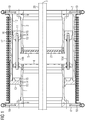
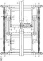
- the Figure 1 shows a section through a pressure vessel arrangement.
- the pressure container arrangement has a first container element 1 and a second container element 2.
- the first and the second container elements 1, 2 are essentially tubular, the two container elements 1, 2 having an essentially circular cross-section.
- the first and second container elements 1, 2 are arranged coaxially to one another, with end faces facing one another at a distance from one another, leaving a compensation gap free.
- the two container elements 1, 2 are arranged coaxially with an axis of symmetry 3.
- a first end body 4 is arranged on the first container element 1 and a second end body 5 is arranged on the second container element 2.
- the end bodies 4, 5 serve to provide a dielectric closure for the container elements 1, 2, so that the compensation gap is dielectrically shielded.
- the two end bodies 4, 5 are each screwed to the respective container element 1, 2 via threaded blind holes.
- the container elements 1, 2 should preferably be shaped in the same way.
- a first connection flange 6 is arranged on the first container element 1 and a second connection flange 7 is arranged on the second container element 2.
- the two connecting flanges 6, 7 are of essentially identical construction.
- the two connecting flanges 6, 7 are each screwed to a circumferential shoulder of the container elements 1, 2 by means of screw connections.
- Both the container elements 1, 2 and the connecting flanges 6, 7 are made of an electrically conductive material, in particular a metal, and are in electrical contact with one another.
- connection flanges 6, 7 and the associated circumferential shoulder each have a sealing element 8, 9 arranged so that there is a fluid-tight transition between the connection flanges 6, 7 and the container elements 1, 2.
- the sealing elements 8, 9 are designed in the form of circumferential, elastically deformable O-rings which are closed in a coaxial manner with respect to the axis of symmetry 3 and which are inserted into a joint gap between the respective connecting flange 6, 7 and the respective container element 1, 2.
- the two container elements 1, 2 are essentially of the same design.
- a preferably circular cylinder-shaped sliding surface is arranged on each of the two container elements 1, 2.
- the sliding surfaces can be formed as free of protrusions as possible.
- it can be provided that sliding surfaces are coated with a varnish, for example.
- Stud bolts 10a, 10b are arranged on the outer circumference of the first end body 4 of the first container element 1.
- the stud bolts 10a, 10b extend essentially parallel to the axis of symmetry 3 and are arranged symmetrically on a revolution around the axis of symmetry 3.
- the stud bolts 10a, 10b are screwed to the first end body 4 by means of nuts.
- the stud bolts 10a, 10b connect a piston 11 to the first end body 4 of the first container element 1.
- the piston 11 is predominantly designed as an annular body which, supported on the stud bolts 10a, 10b, engages around the second container element 2 on the outer jacket side.
- the piston 11 is arranged within a counter-shaped cylinder and is displaceably mounted thereon.
- the cylinder with a circular ring shape is delimited on the inner jacket side by the sliding surface of the second container element 2.
- the cylinder On the outer jacket side, the cylinder is delimited by a support element 12.
- the support element 12 is predominantly shaped in the form of a tube, an inner circumferential surface of the support elements 12 being arranged as a sliding surface to delimit the cylinder (in particular a circular cylindrical inner circumferential surface coaxial with the axis of symmetry 3).
- the support element 12 in the form of a tube is at one end rigidly connected to the second connection flange 7 of the second container element 2, the support element 12 projecting beyond the compensation gap located between the two container elements 1, 2.
- a cylinder base 13 is arranged, which represents a fluid-tight closure of the cylinder.
- the cylinder bottom 13 encompasses the first container element 1 and lies on the sliding surface of the first container element 1 on the outer jacket side.
- the cylinder base 13, the support element 12 and the piston 11 are part of a sealing arrangement by means of which the compensation gap located between the two container elements 1, 2 is sealed in a fluid-tight manner.
- the sealing arrangement has in the cylinder base 13 and the piston 11 a first and a second circumferential groove 14 which is open in the direction of the respective sliding surface of the respective container element 1, 2.
- Elastically deformable sealing elements for example elastomeric O-rings, are inserted in the grooves 14, which form a sliding seal to the respectively assigned sliding surface.
- the grooves 14 in the cylinder base 13 or in the piston 11 are flanked in each case by sliding elements 15 in the axial direction.
- the sliding elements 15 are embedded, for example, in the form of plastic rings in the cylinder base 13 or the piston 11, so that a sliding support effect between the respective sliding surface of the respective container element 1, 2 and the piston 11 or the cylinder base 13 is ensured.
- the sliding elements 15 further protect the sealing elements in the grooves 14 from overstressing.
- the piston 11 which is movable relative to the sliding surface of the second container element 2 and also relative to the support element 12, is provided on its outer peripheral surface with radially outwardly opening grooves 16, in each of which a sealing element is inserted.
- the sealing elements e.g. elastomeric O-rings
- the sealing elements in the radially outward opening grooves 16 seal the piston 11 on the outer jacket side from the sliding surface arranged on the inner jacket side on the support element 12 and each form a sliding seal.
- a fluid-tight barrier is formed above the compensation gap between the two mutually facing ends of the first container element 1 and of the second container element 2 via the piston 11, which is arranged to be movable relative to the second container element 2 and the support element 12, which is movable relative to the first container element 1, or the cylinder base 13 .
- the volume increases or decreases in inverse proportion to a change in the volume of the compensation gap between the two container elements 1, 2.
- a force-relieved relative movement can take place between the first and second container elements 1, 2.
- an almost counterforce-free relative movement can be generated.
- the fluid located under pressure in the pressure vessel arrangement can be relieved of differential pressure forces.
- the sealing arrangement and the first and the second container element 1, 2 are encompassed by an enveloping jacket 17.
- the enveloping jacket 17 is predominantly shaped as a metallic corrugated tube, which has a cross section of this type, which includes both the first and the second container element 1, 2 and the cylinder base 13, the support element 12 and the piston 11 are encompassed by the envelope 17.
- the enveloping jacket 17 is arranged essentially coaxially to the axis of symmetry 3, the metallic corrugated tube being connected at the end in an angularly rigid manner to the first connecting flange 6 and the second connecting flange 7 in the manner of a loose flange arrangement.
- a relative movement of the first and second container elements 1, 2 is also transmitted via the connecting flanges 6, 7 to the enveloping jacket 17 which is rigidly connected to the connecting flanges 6, 7 via loose flange arrangements, so that an elastic deformation of the enveloping jacket 17 can take place.
- first and second overflow channels 18, 19 are arranged in the first and the second connecting flange 6, 7, respectively.
- the overcurrent ducts 18, 19 are each formed identically, a radial blind hole being made in the respective connecting flange 6, 7 to form an overcurrent duct 18, 19, which is completed by an axial blind hole aligned parallel to the axis of symmetry 3 to form a continuous overflow duct 18, 19 .
- An overflow channel 18, 19 thus opens on the one hand in the radial direction in one of the connecting flanges 6, 7 and on the other hand in the axial direction within the hollow volume which is encompassed by the envelope jacket 17.
- the mouth openings of the overflow channels 18, 19 in the connection flanges 6, 7 are each provided with a filter arrangement.
- a phase conductor 20 is arranged inside the pressure vessel arrangement.
- the phase conductor 20 is essentially equipped with a circular cross section, the phase conductor 20 being arranged coaxially with the axis of symmetry 3. It can also be provided that several are parallel to the axis of symmetry 3 aligned phase conductors are located inside the pressure vessel arrangement.
- a pane insulator 21 is arranged on the second container element 2.
- the pane insulator 21 is penetrated centrally by the phase conductor 20, a frame being arranged on the outer circumference of the pane insulator 21. The frame is inserted into the second end body 5 of the second container element 2.
- the pane insulator 21 has recesses so that an electrical insulating fluid, preferably an electrically insulating gas such as sulfur hexafluoride, located inside the pressure container arrangement, that is to say inside the first and second container elements 1, 2, passes through the pane insulator 21 can.
- an electrical insulating fluid preferably an electrically insulating gas such as sulfur hexafluoride
- a fluid-tight barrier using the pane insulator 21 is arranged on the second end body 5 of the second container element 2.
- isolators can also be used, for example rod-shaped isolators, which are arranged radially around the axis of symmetry 3, can position the phase conductor 20 centrally in the pressure vessel arrangement.
- the phase conductor 20 is designed as a waveguide, an intermediate piece made of solid material being used in the area of its mechanical support.
- a tapered section is formed in the intermediate piece, in which a post insulator 21a is screwed.
- the tapered section serves for dielectric shielding of the fastening point and of the fastening means of the post insulator 21a.
- the post insulator 21a is screwed to the phase conductor 20 by a screw. With its end facing away from the phase conductor 20, the support insulator 21a abuts the end body 5 of the second container element 2 on the inner jacket side.
- a plurality of radial recesses are arranged in the end body 5, through which the in Figure 1 Disc insulator 21 shown is screwed to the front body 5.
- the post insulator 21a uses one of these recesses to also be screwed to the front body 5.
- the post insulator 21a can have various shapes.
- the support insulator 21a is equipped with a recess running transversely to the support direction.
Landscapes
- Engineering & Computer Science (AREA)
- Power Engineering (AREA)
- Pressure Vessels And Lids Thereof (AREA)
- Filling Or Discharging Of Gas Storage Vessels (AREA)
Claims (7)
- Agencement de réservoir sous pression ayant une partie de compensation de longueur variable, qui a un premier et un deuxième éléments (1, 2) de réservoir, qui sont mobiles l'un par rapport à l'autre et qui sont reliés entre eux d'une manière étanche au fluide par un agencement (11, 13) d'étanchéité,
l'agencement (11, 13) d'étanchéité étant relié à une étanchéité à glissement, qui fait partie d'une barrière au fluide résistante à la pression et qui est constituée entre une surface de glissement de l'un des éléments (2, 3) du réservoir et un élément étanche de l'agencement d'étanchéité, qui est monté coulissant suivant la surface de glissement, caractérisé en ce que
l'agencement (11, 13) d'étanchéité et l'étanchéité à glissement sont enveloppés d'une enveloppe (17), autour de laquelle passe, du côté de la face intérieure et du côté de la face extérieure, un fluide/des fluides compensés en différence de pression. - Agencement de réservoir sous pression suivant la revendication 1,
caractérisé en ce que
l'enveloppe (17) est en contact, d'une manière conductrice de l'électricité, avec les deux éléments (1, 2) du réservoir et constitue un pont de courant en retour par l'agencement (11, 13) d'étanchéité. - Agencement de réservoir sous pression suivant la revendication 1 ou 2,
caractérisé en ce que,
sur les deux éléments (1, 2) du réservoir, est disposée, à des extrémités éloignées l'une de l'autre, respectivement une bride (6, 7) de liaison, entre lesquelles s'étend l'enveloppe (17). - Agencement de réservoir sous pression suivant l'une des revendications 1 à 3,
caractérisé en ce qu'
un conduit (18, 19) de trop plein met, en communication avec l'atmosphère ambiante de l'enveloppe (17), un volume vide disposé entre l'enveloppe (17) et au moins un élément (1, 2) du réservoir et/ou entre au moins un élément (1, 2) du réservoir et l'agencement (11, 13) d'étanchéité. - Agencement de réservoir sous pression suivant la revendication 4,
caractérisé en ce que
le conduit (18, 19) de trop plein passe, au moins par tronçon, à travers une bride (6, 7) de liaison. - Agencement de réservoir sous pression suivant l'une des revendications 1 à 5,
caractérisé en ce que
l'agencement de réservoir sous pression a un volume de compensation, dans lequel a lieu une variation de volume inversement proportionnelle à la variation d'un volume du réservoir sous pression, le volume de compensation étant enveloppé de l'enveloppe (17). - Agencement de réservoir sous pression suivant la revendication 6,
caractérisé en ce que le volume de compensation est délimité, au moins en partie, par un agencement (11, 12, 13) piston-cylindre, le piston étant relié à angle fixe à l'un des éléments (1, 2) du réservoir et le cylindre (12) à l'autre élément (1, 2) du réservoir.
Applications Claiming Priority (2)
| Application Number | Priority Date | Filing Date | Title |
|---|---|---|---|
| DE102012213438.7A DE102012213438A1 (de) | 2012-07-31 | 2012-07-31 | Druckbehälteranordnung mit einem längenveränderlichen Kompensationsabschnitt |
| PCT/EP2013/064893 WO2014019838A1 (fr) | 2012-07-31 | 2013-07-15 | Système de récipient sous pression comprenant une section de compensation de longueur variable |
Publications (2)
| Publication Number | Publication Date |
|---|---|
| EP2859629A1 EP2859629A1 (fr) | 2015-04-15 |
| EP2859629B1 true EP2859629B1 (fr) | 2020-06-03 |
Family
ID=48874260
Family Applications (1)
| Application Number | Title | Priority Date | Filing Date |
|---|---|---|---|
| EP13740231.9A Active EP2859629B1 (fr) | 2012-07-31 | 2013-07-15 | Agencement de réservoir sous pression avec une section de compensation de longueur variable |
Country Status (5)
| Country | Link |
|---|---|
| EP (1) | EP2859629B1 (fr) |
| CN (1) | CN104521083B (fr) |
| DE (1) | DE102012213438A1 (fr) |
| RU (1) | RU2642855C2 (fr) |
| WO (1) | WO2014019838A1 (fr) |
Families Citing this family (3)
| Publication number | Priority date | Publication date | Assignee | Title |
|---|---|---|---|---|
| DE102018220186A1 (de) | 2018-11-23 | 2020-05-28 | Siemens Aktiengesellschaft | Ventilationsanordnung sowie Vorrichtung mit einer Ventilationsanordnung |
| CN113513649B (zh) * | 2021-05-14 | 2022-09-20 | 深圳大学 | 一种液态铅铋合金输送管道热应力消除装置 |
| DE102024207272A1 (de) * | 2024-07-31 | 2026-02-05 | Siemens Energy Global GmbH & Co. KG | Schiebekompensator mit Klemmring |
Citations (1)
| Publication number | Priority date | Publication date | Assignee | Title |
|---|---|---|---|---|
| US3001801A (en) * | 1961-09-26 | Expansion joint with bellows seal and leakage disposal |
Family Cites Families (8)
| Publication number | Priority date | Publication date | Assignee | Title |
|---|---|---|---|---|
| US4854611A (en) * | 1987-09-24 | 1989-08-08 | Unidynamics Corporation | Fail-safe bellows assembly |
| DE19605979C2 (de) * | 1996-02-17 | 1998-05-28 | Aeg Energietechnik Gmbh | Strom-tragfähiges Verbindungselement für Rohrleitungen einer gasisolierten Schaltanlage |
| DE10246598A1 (de) * | 2002-10-05 | 2004-04-15 | Alstom | Sammelschienenkupplung für eine gasisolierte Schaltanlage |
| DE102005031098A1 (de) * | 2005-06-27 | 2007-01-04 | Siemens Ag | Sich im Wesentlichen rohrförmig erstreckendes Kapselungsgehäuse mit zumindest drei Gehäuseabschnitten |
| DE102008011044A1 (de) * | 2008-02-22 | 2009-08-27 | Siemens Aktiengesellschaft | Druckbehälteranordnung |
| DE102008011042A1 (de) * | 2008-02-22 | 2009-08-27 | Siemens Aktiengesellschaft | Druckbehälteranordnung mit einem Kompensationsbalg |
| DE102008027644A1 (de) * | 2008-06-06 | 2009-12-10 | Siemens Aktiengesellschaft | Kapselungsgehäuseanordnung |
| DE102008027642A1 (de) | 2008-06-06 | 2009-12-10 | Siemens Aktiengesellschaft | Anordnung mit einem Kapselungsgehäuse |
-
2012
- 2012-07-31 DE DE102012213438.7A patent/DE102012213438A1/de not_active Withdrawn
-
2013
- 2013-07-15 EP EP13740231.9A patent/EP2859629B1/fr active Active
- 2013-07-15 WO PCT/EP2013/064893 patent/WO2014019838A1/fr not_active Ceased
- 2013-07-15 RU RU2015106943A patent/RU2642855C2/ru active
- 2013-07-15 CN CN201380040436.7A patent/CN104521083B/zh not_active Expired - Fee Related
Patent Citations (1)
| Publication number | Priority date | Publication date | Assignee | Title |
|---|---|---|---|---|
| US3001801A (en) * | 1961-09-26 | Expansion joint with bellows seal and leakage disposal |
Also Published As
| Publication number | Publication date |
|---|---|
| RU2642855C2 (ru) | 2018-01-29 |
| EP2859629A1 (fr) | 2015-04-15 |
| WO2014019838A1 (fr) | 2014-02-06 |
| DE102012213438A1 (de) | 2014-05-15 |
| CN104521083B (zh) | 2018-06-15 |
| CN104521083A (zh) | 2015-04-15 |
| RU2015106943A (ru) | 2016-09-20 |
Similar Documents
| Publication | Publication Date | Title |
|---|---|---|
| EP2286495B1 (fr) | Dispositif présentant un boîtier d'encapsulage | |
| DE112011103758B4 (de) | Gasisolierte Schalteinrichtung | |
| EP2182602B1 (fr) | Dispositif destiné à une position de connexion entre deux câbles électriques haute tension | |
| EP2676344B1 (fr) | Ensemble boîtier de blindage de longueur variable pour une installation de transmission d'énergie électrique blindée | |
| EP2984718B1 (fr) | Système isolant ainsi que procédé de montage d'un système isolant | |
| EP3724904B1 (fr) | Dispositif de commutation électrique | |
| DE102008011042A1 (de) | Druckbehälteranordnung mit einem Kompensationsbalg | |
| EP2702597A1 (fr) | Coupe-circuit de surtension | |
| DE102011083588A1 (de) | Anordnung aufweisend eine Leistungsschalterunterbrechereinheit | |
| EP2859629B1 (fr) | Agencement de réservoir sous pression avec une section de compensation de longueur variable | |
| EP2281331A2 (fr) | Dispositif de boîtier blindé | |
| DE102011086663A1 (de) | Druckgasisolierte Elektroenergieübertragungseinrichtung | |
| EP2146411A2 (fr) | Couplage de barres collectrices pour une installation de commutation électrique | |
| EP0920705B2 (fr) | Commutateur en charge | |
| EP3048617B1 (fr) | Paratonnerre | |
| EP3093938B1 (fr) | Système d'exécution haute tension | |
| DE102008057237A1 (de) | Druckgasisolierte Elektroenergieübertragungsanordnung | |
| DE19856025C2 (de) | Kompakte Übergangsmuffe | |
| DE102018213905A1 (de) | Längenkompensierende Behälteranordnung | |
| DE102010018063A1 (de) | Kapselungsgehäuseabschnitt einer druckgasisolierten Elektroenergieübertragungseinrichtung | |
| EP4687236A1 (fr) | Compensateur coulissant avec bague de serrage | |
| EP2403087A1 (fr) | Arrangement pour relier deux câbles à haute tension isolés au papier | |
| DE102006033898A1 (de) | Elektrisches Schaltgerät mit einem längs einer Bewegungsachse bewegbaren Kontaktstück | |
| DE102017210934A1 (de) | Isolatoranordnung sowie Montageverfahren zur Herstellung einer Isolatoranordnung | |
| WO2014019837A1 (fr) | Système de brides mobiles pour un dispositif de transmission d'énergie électrique |
Legal Events
| Date | Code | Title | Description |
|---|---|---|---|
| PUAI | Public reference made under article 153(3) epc to a published international application that has entered the european phase |
Free format text: ORIGINAL CODE: 0009012 |
|
| 17P | Request for examination filed |
Effective date: 20150112 |
|
| AK | Designated contracting states |
Kind code of ref document: A1 Designated state(s): AL AT BE BG CH CY CZ DE DK EE ES FI FR GB GR HR HU IE IS IT LI LT LU LV MC MK MT NL NO PL PT RO RS SE SI SK SM TR |
|
| AX | Request for extension of the european patent |
Extension state: BA ME |
|
| DAX | Request for extension of the european patent (deleted) | ||
| RAP1 | Party data changed (applicant data changed or rights of an application transferred) |
Owner name: SIEMENS AKTIENGESELLSCHAFT |
|
| STAA | Information on the status of an ep patent application or granted ep patent |
Free format text: STATUS: EXAMINATION IS IN PROGRESS |
|
| 17Q | First examination report despatched |
Effective date: 20180226 |
|
| GRAP | Despatch of communication of intention to grant a patent |
Free format text: ORIGINAL CODE: EPIDOSNIGR1 |
|
| STAA | Information on the status of an ep patent application or granted ep patent |
Free format text: STATUS: GRANT OF PATENT IS INTENDED |
|
| INTG | Intention to grant announced |
Effective date: 20200120 |
|
| GRAS | Grant fee paid |
Free format text: ORIGINAL CODE: EPIDOSNIGR3 |
|
| GRAA | (expected) grant |
Free format text: ORIGINAL CODE: 0009210 |
|
| STAA | Information on the status of an ep patent application or granted ep patent |
Free format text: STATUS: THE PATENT HAS BEEN GRANTED |
|
| AK | Designated contracting states |
Kind code of ref document: B1 Designated state(s): AL AT BE BG CH CY CZ DE DK EE ES FI FR GB GR HR HU IE IS IT LI LT LU LV MC MK MT NL NO PL PT RO RS SE SI SK SM TR |
|
| REG | Reference to a national code |
Ref country code: GB Ref legal event code: FG4D Free format text: NOT ENGLISH |
|
| REG | Reference to a national code |
Ref country code: CH Ref legal event code: EP Ref country code: AT Ref legal event code: REF Ref document number: 1278013 Country of ref document: AT Kind code of ref document: T Effective date: 20200615 |
|
| REG | Reference to a national code |
Ref country code: DE Ref legal event code: R096 Ref document number: 502013014766 Country of ref document: DE |
|
| REG | Reference to a national code |
Ref country code: CH Ref legal event code: NV Representative=s name: SIEMENS SCHWEIZ AG, CH |
|
| REG | Reference to a national code |
Ref country code: LT Ref legal event code: MG4D |
|
| PG25 | Lapsed in a contracting state [announced via postgrant information from national office to epo] |
Ref country code: FI Free format text: LAPSE BECAUSE OF FAILURE TO SUBMIT A TRANSLATION OF THE DESCRIPTION OR TO PAY THE FEE WITHIN THE PRESCRIBED TIME-LIMIT Effective date: 20200603 Ref country code: LT Free format text: LAPSE BECAUSE OF FAILURE TO SUBMIT A TRANSLATION OF THE DESCRIPTION OR TO PAY THE FEE WITHIN THE PRESCRIBED TIME-LIMIT Effective date: 20200603 Ref country code: SE Free format text: LAPSE BECAUSE OF FAILURE TO SUBMIT A TRANSLATION OF THE DESCRIPTION OR TO PAY THE FEE WITHIN THE PRESCRIBED TIME-LIMIT Effective date: 20200603 Ref country code: GR Free format text: LAPSE BECAUSE OF FAILURE TO SUBMIT A TRANSLATION OF THE DESCRIPTION OR TO PAY THE FEE WITHIN THE PRESCRIBED TIME-LIMIT Effective date: 20200904 Ref country code: NO Free format text: LAPSE BECAUSE OF FAILURE TO SUBMIT A TRANSLATION OF THE DESCRIPTION OR TO PAY THE FEE WITHIN THE PRESCRIBED TIME-LIMIT Effective date: 20200903 |
|
| REG | Reference to a national code |
Ref country code: NL Ref legal event code: MP Effective date: 20200603 |
|
| PG25 | Lapsed in a contracting state [announced via postgrant information from national office to epo] |
Ref country code: HR Free format text: LAPSE BECAUSE OF FAILURE TO SUBMIT A TRANSLATION OF THE DESCRIPTION OR TO PAY THE FEE WITHIN THE PRESCRIBED TIME-LIMIT Effective date: 20200603 Ref country code: RS Free format text: LAPSE BECAUSE OF FAILURE TO SUBMIT A TRANSLATION OF THE DESCRIPTION OR TO PAY THE FEE WITHIN THE PRESCRIBED TIME-LIMIT Effective date: 20200603 Ref country code: BG Free format text: LAPSE BECAUSE OF FAILURE TO SUBMIT A TRANSLATION OF THE DESCRIPTION OR TO PAY THE FEE WITHIN THE PRESCRIBED TIME-LIMIT Effective date: 20200903 Ref country code: LV Free format text: LAPSE BECAUSE OF FAILURE TO SUBMIT A TRANSLATION OF THE DESCRIPTION OR TO PAY THE FEE WITHIN THE PRESCRIBED TIME-LIMIT Effective date: 20200603 |
|
| REG | Reference to a national code |
Ref country code: DE Ref legal event code: R081 Ref document number: 502013014766 Country of ref document: DE Owner name: SIEMENS ENERGY GLOBAL GMBH & CO. KG, DE Free format text: FORMER OWNER: SIEMENS AKTIENGESELLSCHAFT, 80333 MUENCHEN, DE |
|
| PG25 | Lapsed in a contracting state [announced via postgrant information from national office to epo] |
Ref country code: AL Free format text: LAPSE BECAUSE OF FAILURE TO SUBMIT A TRANSLATION OF THE DESCRIPTION OR TO PAY THE FEE WITHIN THE PRESCRIBED TIME-LIMIT Effective date: 20200603 Ref country code: NL Free format text: LAPSE BECAUSE OF FAILURE TO SUBMIT A TRANSLATION OF THE DESCRIPTION OR TO PAY THE FEE WITHIN THE PRESCRIBED TIME-LIMIT Effective date: 20200603 |
|
| RAP2 | Party data changed (patent owner data changed or rights of a patent transferred) |
Owner name: SIEMENS ENERGY GLOBAL GMBH & CO. KG |
|
| PG25 | Lapsed in a contracting state [announced via postgrant information from national office to epo] |
Ref country code: ES Free format text: LAPSE BECAUSE OF FAILURE TO SUBMIT A TRANSLATION OF THE DESCRIPTION OR TO PAY THE FEE WITHIN THE PRESCRIBED TIME-LIMIT Effective date: 20200603 Ref country code: RO Free format text: LAPSE BECAUSE OF FAILURE TO SUBMIT A TRANSLATION OF THE DESCRIPTION OR TO PAY THE FEE WITHIN THE PRESCRIBED TIME-LIMIT Effective date: 20200603 Ref country code: CZ Free format text: LAPSE BECAUSE OF FAILURE TO SUBMIT A TRANSLATION OF THE DESCRIPTION OR TO PAY THE FEE WITHIN THE PRESCRIBED TIME-LIMIT Effective date: 20200603 Ref country code: SM Free format text: LAPSE BECAUSE OF FAILURE TO SUBMIT A TRANSLATION OF THE DESCRIPTION OR TO PAY THE FEE WITHIN THE PRESCRIBED TIME-LIMIT Effective date: 20200603 Ref country code: EE Free format text: LAPSE BECAUSE OF FAILURE TO SUBMIT A TRANSLATION OF THE DESCRIPTION OR TO PAY THE FEE WITHIN THE PRESCRIBED TIME-LIMIT Effective date: 20200603 Ref country code: PT Free format text: LAPSE BECAUSE OF FAILURE TO SUBMIT A TRANSLATION OF THE DESCRIPTION OR TO PAY THE FEE WITHIN THE PRESCRIBED TIME-LIMIT Effective date: 20201006 |
|
| PG25 | Lapsed in a contracting state [announced via postgrant information from national office to epo] |
Ref country code: SK Free format text: LAPSE BECAUSE OF FAILURE TO SUBMIT A TRANSLATION OF THE DESCRIPTION OR TO PAY THE FEE WITHIN THE PRESCRIBED TIME-LIMIT Effective date: 20200603 Ref country code: PL Free format text: LAPSE BECAUSE OF FAILURE TO SUBMIT A TRANSLATION OF THE DESCRIPTION OR TO PAY THE FEE WITHIN THE PRESCRIBED TIME-LIMIT Effective date: 20200603 Ref country code: IS Free format text: LAPSE BECAUSE OF FAILURE TO SUBMIT A TRANSLATION OF THE DESCRIPTION OR TO PAY THE FEE WITHIN THE PRESCRIBED TIME-LIMIT Effective date: 20201003 |
|
| REG | Reference to a national code |
Ref country code: DE Ref legal event code: R097 Ref document number: 502013014766 Country of ref document: DE |
|
| PG25 | Lapsed in a contracting state [announced via postgrant information from national office to epo] |
Ref country code: MC Free format text: LAPSE BECAUSE OF FAILURE TO SUBMIT A TRANSLATION OF THE DESCRIPTION OR TO PAY THE FEE WITHIN THE PRESCRIBED TIME-LIMIT Effective date: 20200603 |
|
| PLBE | No opposition filed within time limit |
Free format text: ORIGINAL CODE: 0009261 |
|
| STAA | Information on the status of an ep patent application or granted ep patent |
Free format text: STATUS: NO OPPOSITION FILED WITHIN TIME LIMIT |
|
| REG | Reference to a national code |
Ref country code: BE Ref legal event code: MM Effective date: 20200731 |
|
| PG25 | Lapsed in a contracting state [announced via postgrant information from national office to epo] |
Ref country code: DK Free format text: LAPSE BECAUSE OF FAILURE TO SUBMIT A TRANSLATION OF THE DESCRIPTION OR TO PAY THE FEE WITHIN THE PRESCRIBED TIME-LIMIT Effective date: 20200603 Ref country code: LU Free format text: LAPSE BECAUSE OF NON-PAYMENT OF DUE FEES Effective date: 20200715 |
|
| 26N | No opposition filed |
Effective date: 20210304 |
|
| PG25 | Lapsed in a contracting state [announced via postgrant information from national office to epo] |
Ref country code: BE Free format text: LAPSE BECAUSE OF NON-PAYMENT OF DUE FEES Effective date: 20200731 Ref country code: SI Free format text: LAPSE BECAUSE OF FAILURE TO SUBMIT A TRANSLATION OF THE DESCRIPTION OR TO PAY THE FEE WITHIN THE PRESCRIBED TIME-LIMIT Effective date: 20200603 |
|
| PG25 | Lapsed in a contracting state [announced via postgrant information from national office to epo] |
Ref country code: IE Free format text: LAPSE BECAUSE OF NON-PAYMENT OF DUE FEES Effective date: 20200715 |
|
| REG | Reference to a national code |
Ref country code: AT Ref legal event code: MM01 Ref document number: 1278013 Country of ref document: AT Kind code of ref document: T Effective date: 20200715 |
|
| PG25 | Lapsed in a contracting state [announced via postgrant information from national office to epo] |
Ref country code: AT Free format text: LAPSE BECAUSE OF NON-PAYMENT OF DUE FEES Effective date: 20200715 |
|
| PGFP | Annual fee paid to national office [announced via postgrant information from national office to epo] |
Ref country code: IT Payment date: 20210722 Year of fee payment: 9 Ref country code: FR Payment date: 20210721 Year of fee payment: 9 |
|
| PGFP | Annual fee paid to national office [announced via postgrant information from national office to epo] |
Ref country code: GB Payment date: 20210802 Year of fee payment: 9 Ref country code: DE Payment date: 20210917 Year of fee payment: 9 |
|
| REG | Reference to a national code |
Ref country code: GB Ref legal event code: 732E Free format text: REGISTERED BETWEEN 20211202 AND 20211209 |
|
| PGFP | Annual fee paid to national office [announced via postgrant information from national office to epo] |
Ref country code: CH Payment date: 20211022 Year of fee payment: 9 |
|
| PG25 | Lapsed in a contracting state [announced via postgrant information from national office to epo] |
Ref country code: TR Free format text: LAPSE BECAUSE OF FAILURE TO SUBMIT A TRANSLATION OF THE DESCRIPTION OR TO PAY THE FEE WITHIN THE PRESCRIBED TIME-LIMIT Effective date: 20200603 Ref country code: MT Free format text: LAPSE BECAUSE OF FAILURE TO SUBMIT A TRANSLATION OF THE DESCRIPTION OR TO PAY THE FEE WITHIN THE PRESCRIBED TIME-LIMIT Effective date: 20200603 Ref country code: CY Free format text: LAPSE BECAUSE OF FAILURE TO SUBMIT A TRANSLATION OF THE DESCRIPTION OR TO PAY THE FEE WITHIN THE PRESCRIBED TIME-LIMIT Effective date: 20200603 |
|
| PG25 | Lapsed in a contracting state [announced via postgrant information from national office to epo] |
Ref country code: MK Free format text: LAPSE BECAUSE OF FAILURE TO SUBMIT A TRANSLATION OF THE DESCRIPTION OR TO PAY THE FEE WITHIN THE PRESCRIBED TIME-LIMIT Effective date: 20200603 |
|
| REG | Reference to a national code |
Ref country code: DE Ref legal event code: R119 Ref document number: 502013014766 Country of ref document: DE |
|
| REG | Reference to a national code |
Ref country code: CH Ref legal event code: PL |
|
| GBPC | Gb: european patent ceased through non-payment of renewal fee |
Effective date: 20220715 |
|
| PG25 | Lapsed in a contracting state [announced via postgrant information from national office to epo] |
Ref country code: LI Free format text: LAPSE BECAUSE OF NON-PAYMENT OF DUE FEES Effective date: 20220731 Ref country code: FR Free format text: LAPSE BECAUSE OF NON-PAYMENT OF DUE FEES Effective date: 20220731 Ref country code: CH Free format text: LAPSE BECAUSE OF NON-PAYMENT OF DUE FEES Effective date: 20220731 |
|
| PG25 | Lapsed in a contracting state [announced via postgrant information from national office to epo] |
Ref country code: GB Free format text: LAPSE BECAUSE OF NON-PAYMENT OF DUE FEES Effective date: 20220715 Ref country code: DE Free format text: LAPSE BECAUSE OF NON-PAYMENT OF DUE FEES Effective date: 20230201 |
|
| PG25 | Lapsed in a contracting state [announced via postgrant information from national office to epo] |
Ref country code: IT Free format text: LAPSE BECAUSE OF NON-PAYMENT OF DUE FEES Effective date: 20220715 |