EP2859847A1 - Blutsammlungsvorrichtung, Lanzette und Lanzettenvorrichtung - Google Patents
Blutsammlungsvorrichtung, Lanzette und Lanzettenvorrichtung Download PDFInfo
- Publication number
- EP2859847A1 EP2859847A1 EP20140184226 EP14184226A EP2859847A1 EP 2859847 A1 EP2859847 A1 EP 2859847A1 EP 20140184226 EP20140184226 EP 20140184226 EP 14184226 A EP14184226 A EP 14184226A EP 2859847 A1 EP2859847 A1 EP 2859847A1
- Authority
- EP
- European Patent Office
- Prior art keywords
- lancet
- lancet holder
- holder
- lancing device
- triggered position
- Prior art date
- Legal status (The legal status is an assumption and is not a legal conclusion. Google has not performed a legal analysis and makes no representation as to the accuracy of the status listed.)
- Withdrawn
Links
- 239000008280 blood Substances 0.000 title claims abstract description 95
- 210000004369 blood Anatomy 0.000 title claims abstract description 95
- 230000001960 triggered effect Effects 0.000 claims description 91
- WQZGKKKJIJFFOK-GASJEMHNSA-N Glucose Natural products OC[C@H]1OC(O)[C@H](O)[C@@H](O)[C@@H]1O WQZGKKKJIJFFOK-GASJEMHNSA-N 0.000 description 5
- 239000008103 glucose Substances 0.000 description 5
- 238000012360 testing method Methods 0.000 description 5
- 238000013461 design Methods 0.000 description 4
- 238000000034 method Methods 0.000 description 4
- 206010011409 Cross infection Diseases 0.000 description 2
- 206010029803 Nosocomial infection Diseases 0.000 description 2
- 230000003247 decreasing effect Effects 0.000 description 2
- 239000002360 explosive Substances 0.000 description 2
- 238000012986 modification Methods 0.000 description 2
- 230000004048 modification Effects 0.000 description 2
- 238000012545 processing Methods 0.000 description 2
- LQIAZOCLNBBZQK-UHFFFAOYSA-N 1-(1,2-Diphosphanylethyl)pyrrolidin-2-one Chemical compound PCC(P)N1CCCC1=O LQIAZOCLNBBZQK-UHFFFAOYSA-N 0.000 description 1
- 238000010420 art technique Methods 0.000 description 1
- 238000003780 insertion Methods 0.000 description 1
- 230000037431 insertion Effects 0.000 description 1
- 238000009434 installation Methods 0.000 description 1
- 239000000463 material Substances 0.000 description 1
Images


Classifications
-
- A—HUMAN NECESSITIES
- A61—MEDICAL OR VETERINARY SCIENCE; HYGIENE
- A61B—DIAGNOSIS; SURGERY; IDENTIFICATION
- A61B5/00—Measuring for diagnostic purposes; Identification of persons
- A61B5/15—Devices for taking samples of blood
- A61B5/150007—Details
- A61B5/150015—Source of blood
- A61B5/150022—Source of blood for capillary blood or interstitial fluid
-
- A—HUMAN NECESSITIES
- A61—MEDICAL OR VETERINARY SCIENCE; HYGIENE
- A61B—DIAGNOSIS; SURGERY; IDENTIFICATION
- A61B5/00—Measuring for diagnostic purposes; Identification of persons
- A61B5/15—Devices for taking samples of blood
- A61B5/151—Devices specially adapted for taking samples of capillary blood, e.g. by lancets, needles or blades
- A61B5/15142—Devices intended for single use, i.e. disposable
- A61B5/15144—Devices intended for single use, i.e. disposable comprising driving means, e.g. a spring, for retracting the piercing unit into the housing
-
- A—HUMAN NECESSITIES
- A61—MEDICAL OR VETERINARY SCIENCE; HYGIENE
- A61B—DIAGNOSIS; SURGERY; IDENTIFICATION
- A61B5/00—Measuring for diagnostic purposes; Identification of persons
- A61B5/14—Devices for taking samples of blood ; Measuring characteristics of blood in vivo, e.g. gas concentration within the blood, pH-value of blood
- A61B5/1405—Devices for taking blood samples
- A61B5/1411—Devices for taking blood samples by percutaneous method, e.g. by lancet
-
- A—HUMAN NECESSITIES
- A61—MEDICAL OR VETERINARY SCIENCE; HYGIENE
- A61B—DIAGNOSIS; SURGERY; IDENTIFICATION
- A61B5/00—Measuring for diagnostic purposes; Identification of persons
- A61B5/15—Devices for taking samples of blood
- A61B5/150007—Details
- A61B5/150175—Adjustment of penetration depth
- A61B5/150198—Depth adjustment mechanism at the proximal end of the carrier of the piercing element
-
- A—HUMAN NECESSITIES
- A61—MEDICAL OR VETERINARY SCIENCE; HYGIENE
- A61B—DIAGNOSIS; SURGERY; IDENTIFICATION
- A61B5/00—Measuring for diagnostic purposes; Identification of persons
- A61B5/15—Devices for taking samples of blood
- A61B5/150007—Details
- A61B5/150206—Construction or design features not otherwise provided for; manufacturing or production; packages; sterilisation of piercing element, piercing device or sampling device
- A61B5/150259—Improved gripping, e.g. with high friction pattern or projections on the housing surface or an ergonometric shape
-
- A—HUMAN NECESSITIES
- A61—MEDICAL OR VETERINARY SCIENCE; HYGIENE
- A61B—DIAGNOSIS; SURGERY; IDENTIFICATION
- A61B5/00—Measuring for diagnostic purposes; Identification of persons
- A61B5/15—Devices for taking samples of blood
- A61B5/150007—Details
- A61B5/150374—Details of piercing elements or protective means for preventing accidental injuries by such piercing elements
- A61B5/150381—Design of piercing elements
- A61B5/150412—Pointed piercing elements, e.g. needles, lancets for piercing the skin
- A61B5/150435—Specific design of proximal end
-
- A—HUMAN NECESSITIES
- A61—MEDICAL OR VETERINARY SCIENCE; HYGIENE
- A61B—DIAGNOSIS; SURGERY; IDENTIFICATION
- A61B5/00—Measuring for diagnostic purposes; Identification of persons
- A61B5/15—Devices for taking samples of blood
- A61B5/150007—Details
- A61B5/150374—Details of piercing elements or protective means for preventing accidental injuries by such piercing elements
- A61B5/150534—Design of protective means for piercing elements for preventing accidental needle sticks, e.g. shields, caps, protectors, axially extensible sleeves, pivotable protective sleeves
- A61B5/150541—Breakable protectors, e.g. caps, shields or sleeves, i.e. protectors separated destructively, e.g. by breaking a connecting area
- A61B5/150549—Protectors removed by rotational movement, e.g. torsion or screwing
-
- A—HUMAN NECESSITIES
- A61—MEDICAL OR VETERINARY SCIENCE; HYGIENE
- A61B—DIAGNOSIS; SURGERY; IDENTIFICATION
- A61B5/00—Measuring for diagnostic purposes; Identification of persons
- A61B5/15—Devices for taking samples of blood
- A61B5/150007—Details
- A61B5/150374—Details of piercing elements or protective means for preventing accidental injuries by such piercing elements
- A61B5/150534—Design of protective means for piercing elements for preventing accidental needle sticks, e.g. shields, caps, protectors, axially extensible sleeves, pivotable protective sleeves
- A61B5/150694—Procedure for removing protection means at the time of piercing
- A61B5/150717—Procedure for removing protection means at the time of piercing manually removed
-
- A—HUMAN NECESSITIES
- A61—MEDICAL OR VETERINARY SCIENCE; HYGIENE
- A61B—DIAGNOSIS; SURGERY; IDENTIFICATION
- A61B5/00—Measuring for diagnostic purposes; Identification of persons
- A61B5/15—Devices for taking samples of blood
- A61B5/151—Devices specially adapted for taking samples of capillary blood, e.g. by lancets, needles or blades
- A61B5/15101—Details
- A61B5/15103—Piercing procedure
- A61B5/15107—Piercing being assisted by a triggering mechanism
- A61B5/15113—Manually triggered, i.e. the triggering requires a deliberate action by the user such as pressing a drive button
-
- A—HUMAN NECESSITIES
- A61—MEDICAL OR VETERINARY SCIENCE; HYGIENE
- A61B—DIAGNOSIS; SURGERY; IDENTIFICATION
- A61B5/00—Measuring for diagnostic purposes; Identification of persons
- A61B5/15—Devices for taking samples of blood
- A61B5/151—Devices specially adapted for taking samples of capillary blood, e.g. by lancets, needles or blades
- A61B5/15101—Details
- A61B5/15115—Driving means for propelling the piercing element to pierce the skin, e.g. comprising mechanisms based on shape memory alloys, magnetism, solenoids, piezoelectric effect, biased elements, resilient elements, vacuum or compressed fluids
- A61B5/15117—Driving means for propelling the piercing element to pierce the skin, e.g. comprising mechanisms based on shape memory alloys, magnetism, solenoids, piezoelectric effect, biased elements, resilient elements, vacuum or compressed fluids comprising biased elements, resilient elements or a spring, e.g. a helical spring, leaf spring, or elastic strap
-
- A—HUMAN NECESSITIES
- A61—MEDICAL OR VETERINARY SCIENCE; HYGIENE
- A61B—DIAGNOSIS; SURGERY; IDENTIFICATION
- A61B5/00—Measuring for diagnostic purposes; Identification of persons
- A61B5/15—Devices for taking samples of blood
- A61B5/151—Devices specially adapted for taking samples of capillary blood, e.g. by lancets, needles or blades
- A61B5/15101—Details
- A61B5/15126—Means for controlling the lancing movement, e.g. 2D- or 3D-shaped elements, tooth-shaped elements or sliding guides
- A61B5/1513—Means for controlling the lancing movement, e.g. 2D- or 3D-shaped elements, tooth-shaped elements or sliding guides comprising linear sliding guides
-
- A—HUMAN NECESSITIES
- A61—MEDICAL OR VETERINARY SCIENCE; HYGIENE
- A61B—DIAGNOSIS; SURGERY; IDENTIFICATION
- A61B5/00—Measuring for diagnostic purposes; Identification of persons
- A61B5/15—Devices for taking samples of blood
- A61B5/151—Devices specially adapted for taking samples of capillary blood, e.g. by lancets, needles or blades
- A61B5/15186—Devices loaded with a single lancet, i.e. a single lancet with or without a casing is loaded into a reusable drive device and then discarded after use; drive devices reloadable for multiple use
- A61B5/15188—Constructional features of reusable driving devices
- A61B5/1519—Constructional features of reusable driving devices comprising driving means, e.g. a spring, for propelling the piercing unit
-
- A—HUMAN NECESSITIES
- A61—MEDICAL OR VETERINARY SCIENCE; HYGIENE
- A61B—DIAGNOSIS; SURGERY; IDENTIFICATION
- A61B5/00—Measuring for diagnostic purposes; Identification of persons
- A61B5/15—Devices for taking samples of blood
- A61B5/151—Devices specially adapted for taking samples of capillary blood, e.g. by lancets, needles or blades
- A61B5/15186—Devices loaded with a single lancet, i.e. a single lancet with or without a casing is loaded into a reusable drive device and then discarded after use; drive devices reloadable for multiple use
- A61B5/15188—Constructional features of reusable driving devices
- A61B5/15192—Constructional features of reusable driving devices comprising driving means, e.g. a spring, for retracting the lancet unit into the driving device housing
- A61B5/15194—Constructional features of reusable driving devices comprising driving means, e.g. a spring, for retracting the lancet unit into the driving device housing fully automatically retracted, i.e. the retraction does not require a deliberate action by the user, e.g. by terminating the contact with the patient's skin
-
- A—HUMAN NECESSITIES
- A61—MEDICAL OR VETERINARY SCIENCE; HYGIENE
- A61B—DIAGNOSIS; SURGERY; IDENTIFICATION
- A61B5/00—Measuring for diagnostic purposes; Identification of persons
- A61B5/15—Devices for taking samples of blood
- A61B5/151—Devices specially adapted for taking samples of capillary blood, e.g. by lancets, needles or blades
- A61B5/15186—Devices loaded with a single lancet, i.e. a single lancet with or without a casing is loaded into a reusable drive device and then discarded after use; drive devices reloadable for multiple use
- A61B5/15188—Constructional features of reusable driving devices
- A61B5/15192—Constructional features of reusable driving devices comprising driving means, e.g. a spring, for retracting the lancet unit into the driving device housing
- A61B5/15196—Constructional features of reusable driving devices comprising driving means, e.g. a spring, for retracting the lancet unit into the driving device housing semi-automatically retracted, i.e. in which the retraction of the piercing unit requires a deliberate action by the user such as manual release of spring-biased retraction means
Definitions
- the present invention relates to a blood collecting apparatus, a lancet, and a lancing device, and more particularly, to a blood collecting apparatus, a lancet, and a lancing device for one time use only.
- a blood collecting apparatus can use its lancet to collect blood sample for further test or processing.
- the blood collecting apparatus can coordinate with a glucose meter by the obtainment of a blood sample of a user, which in turn tests the blood sample and obtains a glucose value of the user.
- US patent application document No. US20070161960 A1 discloses a sleeve-like lancet device having a needle assembly and a needle carrier, the needle assembly having a pin and a pushing rod corresponding to the pin, the pin having an adjusting bolt connected to one end and a spring connected to another end thereof, wherein the spring abuts against a cap; the needle carrier having a needle disposed therein, and a front and a rear stop disposed on the inner surface thereof, the needle forming a single body with a breakable needle hub, wherein the needle hub comprises a safety bolt; a spring plate set is disposed between the needle and the needle carrier.
- a user can insert the lancet into the lancing device to prepare the lancing device for use.
- the pin moves forward to push the lancet to prick and collect blood.
- the elastic force generated by the spring plate set would retract the needle tip back to the needle hub, moreover, due to the design of the front and rear stop, the needle cannot move to an effective triggering position.
- an easy-to-operate blood collecting apparatus, lancet, and lancing device for a user to directly insert the lancet into lancing device to be triggered and collect blood. After blood is collected, the lancet automatically retracts to the inside of the lancing device, making it impossible to be used again. It is necessary to withdraw the lancet and to insert a new one to let the blood collecting apparatus work again.
- the present invention provides a blood collecting apparatus, which comprises a lancet and a lancing device.
- the lancing device is provided for the insertion of the lancet and triggering the lancet to collect blood, the lancing device comprises: a housing, a lancet holder, a triggering mechanism, a withdrawing mechanism, a distance adjusting mechanism, and a cap.
- the housing comprises an upper housing and a lower housing.
- the upper housing and the lower housing are slightly in the shape of a semi ring, respectively. Therefore, the upper housing can combine with the lower housing to form a containing space therebetween.
- the lancet holder is provided inside the housing, the lancet holder can move from a to-be-triggered position to a triggered position for triggering the lancet to collect blood, the lancet holder comprises: a lancet fixing mechanism for fixing the lancet when the lancet holder has the lancet inserted therein and moves to the to-be-triggered position; a to-be-triggered position locating device for positioning the lancet holder at the to-be-triggered position; and a retracting mechanism for retracting the lancet holder to a to-be-withdrawn position when the lancet holder had moved to the triggered position and collected blood, the retracting mechanism comprising: an elastic element, wherein the elastic element is pressed to accumulate an elastic force when the lancet holder moves to the trigged position; the elastic element provides the elastic force to retract the lancet holder to the to-be-withdrawn position.
- the triggering mechanism comprises: a triggering force providing device for providing a triggering force to move the lancet holder from the to-be-triggered position to the triggered position; a releasing device for releasing the lancet holder from the to-be-triggered position to move the lancet holder to the triggered position with the triggering force.
- the withdrawing mechanism comprises: a withdrawing rod for pushing the lancet from a to-be-withdrawn position to a withdrawn position to withdraw the lancet; a restoring device for restoring the withdrawing rod to an initial position after the lancet has been withdrawn; and a force applying device connected with the withdrawing rod, the force applying device being provided for a user to apply a force to move the withdrawing rod.
- the distance adjusting mechanism is disposed at a rear end of the lancet holder, the distance adjusting mechanism comprises: an adjusting knob; a turntable sleeved connected with the adjusting knob, wherein the turntable comprises: a protruding portion corresponding to a slanted groove of the housing; and an inner collar corresponding to an outer collar of a top end of the lancet holder; therefore, when the user is turning the adjusting knob, the adjusting knob drives the protruding portion of the turntable to move along the slanted groove so as to adjust a relative distance between the inner collar and the outer collar of the lancet holder, thereby adjusting a moving distance of the lancet holder moving from the to-be-triggered position to the triggered position.
- the cap is connected to a front end of the housing, the cap comprises a recess corresponding to the convex rail of the lancet.
- the lancet comprises: a needle; a covering portion for covering a rear portion of the needle, the covering portion having a convex rail; and a needle cap for removably covering a front portion of the needle, wherein the needle cap comprises a rotating element for the user to turn the rotating element to remove the needle cap.
- the present invention provides a blood collecting apparatus to collect blood and to obtain a blood sample for further test or processing.
- the blood collecting apparatus can coordinate with a glucose meter by the obtainment of a blood sample of a user, which in turn tests the blood sample and obtains a glucose value of the user.
- the blood collecting apparatus can do more tasks other than working with the glucose meter.
- a user can directly insert the lancet into the to-be-triggered position for subsequent collection of blood. After the lancet is triggered to take blood, the lancet would retract and can be withdrawn. After the lancet is withdrawn, the blood collecting apparatus is restored to the original state for inserting a new lancet to collect blood again.
- FIG.1 to FIG.5 illustrate structural views of the blood collecting apparatus in accordance with one embodiment of the present invention
- FIG.6 to FIG. 12 illustrate the operations of the blood collecting apparatus in an embodiment of the present invention.
- FIG.1 illustrates a combinational view of a blood collecting apparatus in an embodiment of the present invention
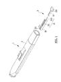
- FIG.2 illustrates an explosive view of the blood collecting apparatus in an embodiment of the present invention
- FIG.3 illustrates a partially combinational view of the blood collecting apparatus in an embodiment of the present invention
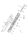
- FIG.4 illustrates a view of a lancet holder of the blood collecting apparatus in an embodiment of the present invention
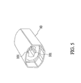
- FIG.5 illustrates a view of a cap of the blood collecting apparatus in an embodiment of the present invention.
- the present invention provides a blood collecting apparatus 1, which comprises a lancet 2 and a lancing device 3.
- the lancing device 3 is provided for inserting the lancet 2 and triggering the lancet 2 to collect blood.
- the lancet 2 comprises a needle 21, a covering portion 22, and a needle cap 23.
- the covering portion 22 is configured to cover a rear portion 211 of the needle 21, and the covering portion 22 comprises a convex rail 221 at its top side and bottom side respectively.
- the needle cap 23 removably covers a front end of the needle 21.
- the needle cap 23 covers the front portion 212 of the needle 21 when the lancet 2 is not in use; the needle cap 23 is removed to expose the front portion 212 of the needle 21 when the lancet 2 is being used to collect blood.
- the needle cap 23 further comprises a rotating element 232 for the user to turn the rotating element 232 to remove the needle cap 23 from outside of the lancing device 3.
- the lancing device 3 comprises a housing 4, a lancet holder 5, a triggering mechanism 6, a withdrawing mechanism 8, a distance adjusting mechanism 9, and a cap 10.
- the housing 4 comprises an upper housing 41 and a lower housing 42.
- the upper housing 41 and the lower housing 42 are slightly in the shape of a semi ring, respectively. Therefore, the upper housing 41 can combine with the lower housing 42 to form a containing space therebetween.
- the upper housing 41 and the lower housing 42 are made of plastic, but they also can be made of other materials.
- the lancet holder 5 is disposed in the containing space formed by the upper housing 41 combining with the lower housing 42.
- the lancet holder 5 is provided for inserting the lancet 2, and the lancet holder 5 can move from a to-be-triggered position to a triggered position to trigger the lancet 2 to collect blood; then the lancet holder 5 can retract to a to-be-withdrawn position after blood is collected.
- Detailed operations of how the lancet holder 5 moves from the to-be-triggered position to the triggered position and then retracts to the to-be-withdrawn position will be described later.
- the lancet holder 5 comprises: a lancet fixing mechanism 51, a to-be-triggered position locating device 52, at least one guide rib 53, a retaining bump 54, an outer collar 55, and a retracting mechanism 57.
- the lancet fixing mechanism 51 is used for fixing the lancet 2;
- the to-be-triggered position locating device 52 is configured to position the lancet holder 5 at the to-be-triggered position;
- the at least one guide rib 53 is used for guiding the lancet holder 5 to move smoothly along with the direction it leads;
- the retaining bump 54 is used for working with the limit bar 85 of the housing 4 to limit the movement of the lancet holder 5 when the lancet 2 is withdrawn from the lancet holder 5;
- the outer collar 55 is fixed in the distance adjusting mechanism 9 and works with the distance adjusting mechanism 9 to adjust a moving distance of the lancet holder 5 moving from the to-be-triggered position to the triggered position. Detailed operations of how to adjust the moving distance of the lancet holder 5 will be described later.
- the lancet fixing mechanism 51 comprises a clamp opening 510, the clamp opening 510 comprises a clamping piece 512, the clamping piece 512 comprising an opening 514 for the convex rail 221 of the lancet 2 to go through the opening514.
- the lancet fixing mechanism 51 is disposed to work with the convex step 516 disposed on the lower housing 42.
- the convex step 516 presses the clamping piece 512 to move upwards to decrease an aperture of the clamp opening 510 so as to fixedly clamp the lancet 2.
- the lancet fixing mechanism 51 works with the convex step 516 to prevent the user from withdrawing the lancet, while allows the needle cap 23 of the lancet 2 to be moved smoothly, thereby assuring the safety in operation.
- the to-be-triggered position locating device 52 can be a bump 52 disposed on the lancet holder 5, when the lancet holder 5 moves to the to-be-triggered position, the bump 52 abuts against the upper housing 41 to position the lancet holder 5 at the to-be-triggered position.
- the at least one guide rib 53 corresponds to the at least one recess guide groove 44 of the housing 4 to let the lancet holder 5 move smoothly along the direction guided by the recess guide groove 44.
- the outer collar 55 is fixed in the distance adjusting mechanism 9 and blocked by the inner collar 922 of the distance adjusting mechanism 9, so the distance between the outer collar 55 and the inner collar 922 is the moving distance when the lancet holder 5 is being triggered.
- the position of the outer collar 55 of the lancet holder 5 is fixed, therefore, the moving distance of the lancet holder 5 moving from the to-be-triggered position to the triggered position can be adjusted by using the distance adjusting mechanism 9 to move the position of the inner collar 922.
- Detailed operations of how to adjust the moving distance of the lancet holder 5 will be described later.
- the retracting mechanism 57 comprises elastic elements 571 and 572 disposed at two sides of the lancet holder 5 respectively.
- the elastic elements 571 and 572 are deformed by the ramp members 573 and 574 of the lower housing 42 to accumulate an elastic force.
- the push force from the spring 61 vanishes, while the elastic elements 571 and 572 release the accumulated elastic force to pull back the lancet holder 5, thereby retracting the lancet holder 5 and the lancet 2 to the to-be-withdrawn position.
- the lancet 2 retracts back to the inside of the cap 10, or any other designated position.
- the triggering mechanism 6 is used for triggering the lancet holder 5 to let the lancet holder 5 move from the to-be-triggered position to the triggered position to enable the lancet 2 to collect blood.
- the triggering mechanism 6 comprises: a triggering force providing device 61 and a releasing device 62.
- the triggering force providing device 61 provides a triggering force needed for moving the lancet holder 5 from the to-be-triggered position to the triggered position; the releasing device 62 releases the lancet holder 5 from the to-be-triggered position to let the triggering force move the lancet holder 5 to the triggered position.
- the triggering force providing device 61 can be a spring disposed between the distance adjusting mechanism 9 and the lancet holder 5, when the lancet holder 5 moves to the to-be-triggered position, the lancet holder 5 compresses the spring 61 to use a spring force of the spring 61 to provide the triggering force needed for moving the lancet holder 5 to the triggered position.
- the releasing device 62 can be a button disposed on the upper housing 41, when the button 62 is pressed, the to-be-triggered position locating device 52 can be released to let the lancet holder 5 move by the spring force of the spring 61.
- the withdrawing mechanism 8 is provided for withdrawing the lancet 2 to replace a new lancet 2 to collect blood again.
- the withdrawing mechanism 8 comprises: a withdrawing rod 81, a restoring device 82, and a force applying device 83.
- the withdrawing rod 81 may be provided for pushing the lancet 2 from a to-be-withdrawn position to a withdrawn position to withdraw the lancet 2.
- the restoring device 82 is provided for restoring the withdrawing rod 81 to an initial position after the lancet 2 has been withdrawn.
- the force applying device 83 is connected with the withdrawing rod 81 and provided for a user to apply a force to move the withdrawing rod 81.
- the restoring device 82 can be a spring sleeved on the withdrawing rod 81.
- the withdrawing rod 81 pushes the lancet 2 to move from the to-be-withdrawn position to the withdrawn position, the spring 82 is compressed to generate an elastic force. Therefore, after the lancet 2 is withdrawn, the elastic force of the spring 82 can bring the withdrawing rod 81 back to the initial position.
- the withdrawing rod 81 and the restoring device 82 are disposed inside the lancet holder 5, or they can be disposed at any designated positions.
- the force applying device 83 is a push button 83
- the push button 83 goes through an open slot between the upper housing 41 and the lower housing 42 to protrude out of the housing 4; the push button 83 may be provided for the user to push the push button 83 along the open slot to move the withdrawing rod 81.
- the push button 83 when the user can't move the push button 83, he/she would find out that the lancing device 3 is in the to-be-triggered state and the lancet 2 can only be withdrawn after being triggered.
- this safety design can help the user find out the current state of the lancing device 3.
- the withdrawing mechanism further comprises a press bar 84 and a limit bar 85.
- the press bar 84 moves with the withdrawing rod 81; and the limit bar 85 may be disposed on the lower housing 42.
- the press bar 84 moves with the withdrawing rod 81 and presses the limit bar 85, which in turn presses the lancet holder 5 to limit the movement of the lancet holder 5.
- the lancet holder 5 comprises a retaining bump 54 working with the limit bar 85.
- the limit bar 85 presses the retaining bump 54 to assure that the lancet holder 5 can't be moved, thereby allowing the lancet 2 to be smoothly withdrawn from the lancet holder 5.
- the distance adjusting mechanism 9 is disposed at a rear end of the lancet holder 5 and is provided for adjusting a moving distance of the lancet holder 5 moving from the to-be-triggered position to the triggered position.
- the distance adjusting mechanism 9 comprises an adjusting knob 91 and a turntable 92.
- the adjusting knob 91 is disposed at a rear end of the housing 4; the turntable 92 is sleeved connected with the adjusting knob 91, wherein the turntable 92 comprises a protruding portion 921 and an inner collar 922.
- the protruding portion 921 corresponds to a slanted groove 46 of the upper housing 42; and the inner collar 922 corresponds to an outer collar 55 of a top end of the lancet holder 5.
- the adjusting knob 91 drives the protruding portion 921 of the turntable 92 to move along the slanted groove 46 so as to adjust a relative distance between the inner collar 922 and the outer collar 55 of the lancet holder 5, thereby adjusting a moving distance of the lancet holder 5 moving from the to-be-triggered position to the triggered position.
- the outer collar (not shown in figure) can be disposed on the turntable 92, and a corresponding inner collar (not shown in figure) can be disposed on top of the lancet holder 5; there are also other possible configurations.
- the adjusting knob 91 comprises a positioning bump 911
- the upper housing 41 comprises a plurality of positioning grooves 45 working with the positioning bump 911 to position the adjusting knob 91 when the adjusting knob 91 is turned to drive the turntable 92 to move to a specific height.
- the adjusting knob 91 comprises a concave arc portion 912 working with the protruding portion 921 of the turntable 92.
- the distance adjusting mechanism 9 can adjust a sliding distance of the lancet holder 5; therefore, the blood collecting apparatus 1 can adjust the moving distance of the lancet 2, thereby allowing the blood collecting apparatus 1 to be applied to people of different ages and requirements.
- the cap 10 is connected to a front end of the housing 4, the lancet 2 goes through the cap 10 to be inserted in housing 4.
- the cap 10 comprises a recess 101 corresponding to the convex rail 221 of the lancet 2 to place the lancet 2 firmly in the housing 4.
- the cap 10 can help to reduce the shaking or swaying when the lancet 2 is triggered to successfully soothe the uncomfortable feeling of the user.
- FIG.6 illustrates a view of the blood collecting apparatus without the lancet in an embodiment of the present invention
- FIG.7 illustrates a view of the blood collecting apparatus with the lancet inserted in an embodiment of the present invention
- FIG.8 illustrates a view of the blood collecting apparatus with the lancet inserted and the needle cap removed in an embodiment of the present invention
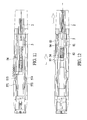
- FIG.9 illustrates a view of the blood collecting apparatus being triggered in an embodiment of the present invention
- FIG.10 illustrates an another view of the blood collecting apparatus being triggered in an embodiment of the present invention
- FIG.11 illustrates a view of the blood collecting apparatus having the lancet retracted in an embodiment of the present invention
- FIG.12 illustrates a view of withdrawing the lancet of the blood collecting apparatus in an embodiment of the present invention.
- the clamping piece 512 is not in contact with the convex step 516, and the clamp opening 510 remains its initial aperture; the bump 52 is not in contact with the edge 43 of the upper housing 41; and the spring 61 is no compressed yet.
- the lancet 2 when the lancet 2 is inserted in the lancing device 3, the lancet 2 pushes the lancet holder 5 to move upwards, the clamping piece 512 is pressed by the convex step 516 to decrease the aperture of the clamp opening 510 so as to fixedly clamp the lancet 2; the bump 52 moves backward and protrudes out from the edge 43 of the upper housing 41, the bump 52 also pushes the button 62 upwards to protrude out of the housing 4; and the spring 61 is also compressed.
- the bump 52 is pushed by the elastic force of the spring 61 to abut against the edge 43 of the upper housing 41, as the bump 52 is stuck with the edge 43 of the upper housing 41, the lancet holder 5 is held at the to-be-triggered position.
- the bump 52 is recessed from or forced to separate from the edge 43 of the upper housing 41, at this time the spring 61 provides the triggering force needed for moving the lancet holder 5 to the triggered position, thereby allowing the tip of the lancet 2 to protrude out of the cap 10 to collect blood.
- the lancet holder 5 when the lancet holder 5 has moved to the triggered position to collect blood, the elastic elements 571 and 572 are pressed and deformed by the ramp members 573 and 574 of the lower housing 42 to accumulate an elastic force.
- the spring force from the spring 61 vanishes, the elastic elements 571 and 572 will restore their original form and release the accumulated elastic force, as shown in FIG.11 , the lancet holder 5 retracts to bring the lancet 2 back to the to-be-withdrawn position. Therefore, the lancet 2 of the blood collecting apparatus 1 can be used for collecting blood, after the lancet 2 has collected blood, the lancet 2 can be retracted and ready for withdrawing.
- the clamp opening 510 restores its original aperture. Then the user can push the push button 83 to move the withdrawing rod 81 forward and to push the lancet 2 out of the lancet fixing mechanism 51 to withdraw the lancet 2. Furthermore, when the withdrawing rod 81 moves, the press bar 84 will move along to abut against the limit bar 85 and limits the limit bar 85 from restoring to the initial position; meanwhile the limit bar 85 presses the retaining bump 54 of the lancet holder 5 to limit the movement of the lancet holder 5. After the lancet 2 is withdrawn, the spring force of the spring 82 restores the withdrawing rod 81 to its initial position. Then the user can insert a new lancet 2 to collect blood again.
- the lancet fixing mechanism 51 can have the whole lower plane of the clamp opening 510 disposed with the clamping piece 512 as shown in FIG.4 ; or in another embodiment of the present invention, the lancet fixing mechanism 51 can have the lower plane of the clamp opening 510 partially disposed with the clamping piece 512. Therefore, when the lancet 2 is inserted in the lancet fixing mechanism 51, the lancet 2 will be in contact with the lower plane of the clamp opening 510 not disposed with the clamping piece 512. This multi-point contact design will help to further fix the lancet 2 in the lancet fixing mechanism 51. Besides, this design can reduce the risk of the lancet 2 falling off when it is retracting.
- FIG. 14 illustrates a view of the lancet holder with the original moving distance
- FIG.15 illustrates a view of the lancet holder with a decreased moving distance
- FIG.16 illustrates a view of the lancet holder with an increased moving distance.
- the protruding portion 921 of the turntable 92 is located at the center position of the slanted groove 46.
- the adjusting knob 91 drives the turntable 92 to move along with the slanted groove 46 to ascend, thereby positioning the protruding portion 921 at an upper position of the slanted groove 46 and also reducing the relative distance between the inner collar 922 and the outer collar 55 of the lancet holder 5.
- the lancet holder 5 When the lancet holder 5 is triggered, the lancet holder 5 will move until the outer collar 55 of the lancet holder 5 is blocked by the inner collar 922; therefore, the maximum moving distance is the distance between the inner collar 922 and the outer collar 55. Hence, the moving distance of the lancet holder 5 can be shortened by reducing the distance between the inner collar 922 and the outer collar 55.
- the adjusting knob 91 drives the turntable 92 to move along with the slanted groove 46 to descend, thereby positioning the protruding portion 921 at an lower position of the slanted groove 46 and also increasing the relative distance between the inner collar 922 and the outer collar 55 of the lancet holder 5.
- the user can adjust the moving distance of the lancet holder 5 to meet different requirements.
- the upper end of the lancet holder 5 is first inserted to the bottom of the turntable 92, then the outer collar 55 of the lancet holder 5 passes through the inner collar 922 corresponding to the bottom of the turntable 92, thereby allowing the upper end of the lancet holder 5 to be fixed in the turntable 92.
- the withdrawing rod 81 of the withdrawing mechanism 8 is sleeved with one end of the spring 82, and the other end of the spring 82 is fitted in a notch at the lower side of the lower housing 42, and the limit bar 85 is fitted in a notch at a side of the lower housing 42.
- the sleeved lancet holder 5 is inserted in the lower housing 42 with the withdrawing rod 81 of the withdrawing mechanism 8 disposed in the inner space of the lancet holder 5.
- the elastic elements 571 and 572 of the retracting mechanism 57 of the lancet holder 5 are right at the positions of the ramp members 573 and 574 of the lower housing 42 respectively.
- the spring 61 passes through the turntable 92 to be disposed on the upper end of the lancet holder 5.
- the releasing device 62 is disposed on the upper housing 41, and the adjusting knob 91 is sleeved to the turntable 92. Then the upper housing 41 is combined with the lower housing 42. Finally the user can align the cap 10 to the front end of the housing 4 and press the cap 10 into the housing to combine the upper housing 41, the lower housing 42, and the cap 10 as one unit to complete the assembling process.
- the user can insert the lancet 2 through the cap 10 of the lancing device 3 to the lancet holder 5, as the lancet 2 is pushed to the very end of the lancet holder, the user can have the lancing device 3 loaded and the lancet located at the to-be-triggered position. Then the user can turn the needle cap 23 to expose the lancet 2, point the lancing device 3 at the target area (such as finger) and press the button 62, then the lancet 2 would be triggered to collect blood. After the lancet 2 collects blood, it will retract to the inside of the lancing device 3.
- the user can only withdraw the lancet and replace a new one to be loaded to the to-be-triggered position and to collect blood.
- the total length of the covering portion 22 of the lancet 2 plus the needle cap 23 is longer than the distance between the front end of the cap 10 of the lancing device 3 and the to-be-triggered position of the lancet holder 5 and the total length of the used lancet 2 (without the needle cap 23) is shorter, it is not possible to insert the used lancet again. Therefore, the lancet can be used for one time only to eliminate the possible cross infection risk. Meanwhile, the lancet 2 will automatically retract to the inside of the lancing device 3 to prevent any risk of the lancet 2 mistakenly pricking any one, thereby assuring the safety in the process of blood collection.
- the method for using the lancet to collect the blood sample includes: piercing through the user's skin to collect the blood sample directly; or piercing through the user's skin to leave the blood sample flowing to the surface of the user's skin for being further collected.
Landscapes
- Health & Medical Sciences (AREA)
- Life Sciences & Earth Sciences (AREA)
- Engineering & Computer Science (AREA)
- Heart & Thoracic Surgery (AREA)
- Molecular Biology (AREA)
- Pathology (AREA)
- Physics & Mathematics (AREA)
- Biomedical Technology (AREA)
- Hematology (AREA)
- Medical Informatics (AREA)
- Biophysics (AREA)
- Surgery (AREA)
- Animal Behavior & Ethology (AREA)
- General Health & Medical Sciences (AREA)
- Public Health (AREA)
- Veterinary Medicine (AREA)
- Dermatology (AREA)
- Manufacturing & Machinery (AREA)
- Measurement Of The Respiration, Hearing Ability, Form, And Blood Characteristics Of Living Organisms (AREA)
Applications Claiming Priority (1)
| Application Number | Priority Date | Filing Date | Title |
|---|---|---|---|
| TW102136860A TW201513832A (zh) | 2013-10-11 | 2013-10-11 | 採血裝置及其採血針與採血筆 |
Publications (1)
| Publication Number | Publication Date |
|---|---|
| EP2859847A1 true EP2859847A1 (de) | 2015-04-15 |
Family
ID=51627938
Family Applications (1)
| Application Number | Title | Priority Date | Filing Date |
|---|---|---|---|
| EP20140184226 Withdrawn EP2859847A1 (de) | 2013-10-11 | 2014-09-10 | Blutsammlungsvorrichtung, Lanzette und Lanzettenvorrichtung |
Country Status (8)
| Country | Link |
|---|---|
| US (1) | US20150105813A1 (de) |
| EP (1) | EP2859847A1 (de) |
| KR (1) | KR20150042702A (de) |
| AR (1) | AR097728A1 (de) |
| AU (1) | AU2014224070A1 (de) |
| CA (1) | CA2864585A1 (de) |
| MX (1) | MX2014012300A (de) |
| TW (1) | TW201513832A (de) |
Cited By (3)
| Publication number | Priority date | Publication date | Assignee | Title |
|---|---|---|---|---|
| CN109260534A (zh) * | 2018-10-18 | 2019-01-25 | 泰州市人民医院 | 一种血袋血辫用一次性取血器 |
| GB2568025A (en) * | 2017-09-29 | 2019-05-08 | Owen Mumford Ltd | A blood sampling device |
| CN111419243A (zh) * | 2020-04-21 | 2020-07-17 | 苏州施莱医疗器械有限公司 | 一种利用尾拉手上膛和调节深度的采血笔 |
Families Citing this family (10)
| Publication number | Priority date | Publication date | Assignee | Title |
|---|---|---|---|---|
| JP7092747B2 (ja) | 2016-08-24 | 2022-06-28 | ベクトン・ディキンソン・アンド・カンパニー | 血液の付着流のための装置 |
| CN111493890A (zh) * | 2019-01-31 | 2020-08-07 | 北京万禾君邦科技有限公司 | 采血笔 |
| CN111214241A (zh) * | 2019-05-12 | 2020-06-02 | 天津华鸿科技股份有限公司 | 采血笔 |
| CN111214247B (zh) * | 2020-01-22 | 2025-01-03 | 苏州市振吴医疗用品有限公司 | 足跟采血针 |
| CN115475324B (zh) * | 2021-06-16 | 2025-09-16 | 苏州悦肤达医疗科技有限公司 | 一种助针器及医用装置 |
| CN115399767A (zh) * | 2021-08-09 | 2022-11-29 | 天津华鸿科技股份有限公司 | 一种采血笔 |
| CN113866142A (zh) * | 2021-09-13 | 2021-12-31 | 苏州优印佳防伪科技有限公司 | 一种多光谱防伪检测系统及检测装置 |
| US20230266204A1 (en) * | 2022-02-22 | 2023-08-24 | True Diagnostics | Dried blood sample collection device |
| CN114886482A (zh) * | 2022-05-19 | 2022-08-12 | 苏州市立普医疗科技有限公司 | 活检枪侧推钮结构和活检枪 |
| CN116919400B (zh) * | 2023-07-14 | 2025-06-03 | 苏州施莱医疗器械有限公司 | 防二次使用末梢采血器 |
Citations (5)
| Publication number | Priority date | Publication date | Assignee | Title |
|---|---|---|---|---|
| US6045567A (en) * | 1999-02-23 | 2000-04-04 | Lifescan Inc. | Lancing device causing reduced pain |
| WO2001013794A1 (en) * | 1999-08-19 | 2001-03-01 | Owen Mumford Limited | Lancet |
| US20070161960A1 (en) | 2006-01-12 | 2007-07-12 | Fu-Yuan Li | Lancet device |
| US20100094324A1 (en) * | 2008-10-14 | 2010-04-15 | Bionime Corporation | Lancing device |
| WO2012137001A1 (en) * | 2011-04-08 | 2012-10-11 | Owen Mumford Limited | Skin penetration device |
Family Cites Families (7)
| Publication number | Priority date | Publication date | Assignee | Title |
|---|---|---|---|---|
| CA2079192C (en) * | 1992-09-25 | 1995-12-26 | Bernard Strong | Combined lancet and multi-function cap and lancet injector for use therewith |
| US5628765A (en) * | 1994-11-29 | 1997-05-13 | Apls Co., Ltd. | Lancet assembly |
| US6053930A (en) * | 1998-05-11 | 2000-04-25 | Ruppert; Norbert | Single use lancet assembly |
| US8449480B2 (en) * | 2008-08-07 | 2013-05-28 | Nova Biomedical Corporation | Single use lancet sensor assembly and meter |
| JP5540617B2 (ja) * | 2009-09-10 | 2014-07-02 | ニプロ株式会社 | ディスポーザブル型採血器具 |
| JP5336601B2 (ja) * | 2009-10-07 | 2013-11-06 | 株式会社旭ポリスライダー | ランセット穿刺デバイス |
| JP5753071B2 (ja) * | 2011-12-20 | 2015-07-22 | 泉株式会社 | ランセットアッセンブリおよび穿刺デバイス |
-
2013
- 2013-10-11 TW TW102136860A patent/TW201513832A/zh unknown
-
2014
- 2014-09-09 US US14/481,052 patent/US20150105813A1/en not_active Abandoned
- 2014-09-10 EP EP20140184226 patent/EP2859847A1/de not_active Withdrawn
- 2014-09-11 AU AU2014224070A patent/AU2014224070A1/en not_active Abandoned
- 2014-09-12 KR KR20140121020A patent/KR20150042702A/ko not_active Abandoned
- 2014-09-19 CA CA 2864585 patent/CA2864585A1/en not_active Abandoned
- 2014-09-23 AR ARP140103508A patent/AR097728A1/es unknown
- 2014-10-10 MX MX2014012300A patent/MX2014012300A/es unknown
Patent Citations (5)
| Publication number | Priority date | Publication date | Assignee | Title |
|---|---|---|---|---|
| US6045567A (en) * | 1999-02-23 | 2000-04-04 | Lifescan Inc. | Lancing device causing reduced pain |
| WO2001013794A1 (en) * | 1999-08-19 | 2001-03-01 | Owen Mumford Limited | Lancet |
| US20070161960A1 (en) | 2006-01-12 | 2007-07-12 | Fu-Yuan Li | Lancet device |
| US20100094324A1 (en) * | 2008-10-14 | 2010-04-15 | Bionime Corporation | Lancing device |
| WO2012137001A1 (en) * | 2011-04-08 | 2012-10-11 | Owen Mumford Limited | Skin penetration device |
Cited By (6)
| Publication number | Priority date | Publication date | Assignee | Title |
|---|---|---|---|---|
| GB2568025A (en) * | 2017-09-29 | 2019-05-08 | Owen Mumford Ltd | A blood sampling device |
| US11992315B2 (en) | 2017-09-29 | 2024-05-28 | Owen Mumford Limited | Blood sampling device |
| CN109260534A (zh) * | 2018-10-18 | 2019-01-25 | 泰州市人民医院 | 一种血袋血辫用一次性取血器 |
| CN109260534B (zh) * | 2018-10-18 | 2024-06-04 | 泰州市人民医院 | 一种血袋血辫用一次性取血器 |
| CN111419243A (zh) * | 2020-04-21 | 2020-07-17 | 苏州施莱医疗器械有限公司 | 一种利用尾拉手上膛和调节深度的采血笔 |
| CN111419243B (zh) * | 2020-04-21 | 2021-11-16 | 苏州施莱医疗器械有限公司 | 一种利用尾拉手上膛和调节深度的采血笔 |
Also Published As
| Publication number | Publication date |
|---|---|
| US20150105813A1 (en) | 2015-04-16 |
| MX2014012300A (es) | 2015-04-28 |
| AU2014224070A1 (en) | 2015-04-30 |
| AR097728A1 (es) | 2016-04-13 |
| TW201513832A (zh) | 2015-04-16 |
| KR20150042702A (ko) | 2015-04-21 |
| CA2864585A1 (en) | 2015-04-11 |
Similar Documents
| Publication | Publication Date | Title |
|---|---|---|
| EP2859847A1 (de) | Blutsammlungsvorrichtung, Lanzette und Lanzettenvorrichtung | |
| US20170000517A1 (en) | High speed lancing device with lancet ejection assembly | |
| US8568434B2 (en) | Lancing device | |
| EP1865849B1 (de) | Lanzettenvorrichtung mit druckbetätigung | |
| CN101146477B (zh) | 用于提取体液的刺入系统 | |
| US9386945B2 (en) | Blood lancing device | |
| EP0115388A1 (de) | Blutentnahmegerät | |
| JPH038217B2 (de) | ||
| CN101309642A (zh) | 采血装置及其使用方法 | |
| CN105105765B (zh) | 皮肤穿透装置 | |
| EP2050393A1 (de) | Stechvorrichtung | |
| KR20120050525A (ko) | 일회용 채혈 기구 | |
| CN216754451U (zh) | 一种采血笔 | |
| KR101491812B1 (ko) | 채혈기 | |
| US20210275067A1 (en) | Blood withdrawal system with lancet ejection mechanism | |
| EP1901658B1 (de) | Hautpunktionssystem | |
| US8323303B2 (en) | Lancing device | |
| CN104510480B (zh) | 穿刺装置 | |
| US20140214065A1 (en) | Blood lancet device | |
| US20170251964A1 (en) | Blood sampling device | |
| JP2014200473A (ja) | 穿刺装置及び穿刺システム | |
| EP3111844A1 (de) | Hochschnelle lanzettenvorrichtung mit lanzetten ausstossanordnung | |
| TWM473193U (zh) | 採血裝置及其採血針與採血筆 | |
| US10646150B2 (en) | Lancing device | |
| KR20100007026A (ko) | 란셋 및 이를 구비한 랜싱장치 |
Legal Events
| Date | Code | Title | Description |
|---|---|---|---|
| PUAI | Public reference made under article 153(3) epc to a published international application that has entered the european phase |
Free format text: ORIGINAL CODE: 0009012 |
|
| 17P | Request for examination filed |
Effective date: 20140910 |
|
| AK | Designated contracting states |
Kind code of ref document: A1 Designated state(s): AL AT BE BG CH CY CZ DE DK EE ES FI FR GB GR HR HU IE IS IT LI LT LU LV MC MK MT NL NO PL PT RO RS SE SI SK SM TR |
|
| AX | Request for extension of the european patent |
Extension state: BA ME |
|
| STAA | Information on the status of an ep patent application or granted ep patent |
Free format text: STATUS: THE APPLICATION IS DEEMED TO BE WITHDRAWN |
|
| 18D | Application deemed to be withdrawn |
Effective date: 20151016 |