EP2859859B1 - Dispositif de traitement ultrasonore chirurgical - Google Patents
Dispositif de traitement ultrasonore chirurgical Download PDFInfo
- Publication number
- EP2859859B1 EP2859859B1 EP13800806.5A EP13800806A EP2859859B1 EP 2859859 B1 EP2859859 B1 EP 2859859B1 EP 13800806 A EP13800806 A EP 13800806A EP 2859859 B1 EP2859859 B1 EP 2859859B1
- Authority
- EP
- European Patent Office
- Prior art keywords
- treatment
- distal end
- ultrasonic
- region
- grasp
- Prior art date
- Legal status (The legal status is an assumption and is not a legal conclusion. Google has not performed a legal analysis and makes no representation as to the accuracy of the status listed.)
- Active
Links
Images


Classifications
-
- A—HUMAN NECESSITIES
- A61—MEDICAL OR VETERINARY SCIENCE; HYGIENE
- A61B—DIAGNOSIS; SURGERY; IDENTIFICATION
- A61B18/00—Surgical instruments, devices or methods for transferring non-mechanical forms of energy to or from the body
- A61B18/04—Surgical instruments, devices or methods for transferring non-mechanical forms of energy to or from the body by heating
- A61B18/12—Surgical instruments, devices or methods for transferring non-mechanical forms of energy to or from the body by heating by passing a current through the tissue to be heated, e.g. high-frequency current
- A61B18/14—Probes or electrodes therefor
- A61B18/1442—Probes having pivoting end effectors, e.g. forceps
- A61B18/1445—Probes having pivoting end effectors, e.g. forceps at the distal end of a shaft, e.g. forceps or scissors at the end of a rigid rod
-
- A—HUMAN NECESSITIES
- A61—MEDICAL OR VETERINARY SCIENCE; HYGIENE
- A61B—DIAGNOSIS; SURGERY; IDENTIFICATION
- A61B17/00—Surgical instruments, devices or methods
- A61B2017/00831—Material properties
- A61B2017/0084—Material properties low friction
- A61B2017/00849—Material properties low friction with respect to tissue, e.g. hollow organs
-
- A—HUMAN NECESSITIES
- A61—MEDICAL OR VETERINARY SCIENCE; HYGIENE
- A61B—DIAGNOSIS; SURGERY; IDENTIFICATION
- A61B17/00—Surgical instruments, devices or methods
- A61B2017/00831—Material properties
- A61B2017/00942—Material properties hydrophilic
-
- A—HUMAN NECESSITIES
- A61—MEDICAL OR VETERINARY SCIENCE; HYGIENE
- A61B—DIAGNOSIS; SURGERY; IDENTIFICATION
- A61B17/00—Surgical instruments, devices or methods
- A61B17/28—Surgical forceps
- A61B17/2812—Surgical forceps with a single pivotal connection
- A61B17/282—Jaws
- A61B2017/2825—Inserts of different material in jaws
-
- A—HUMAN NECESSITIES
- A61—MEDICAL OR VETERINARY SCIENCE; HYGIENE
- A61B—DIAGNOSIS; SURGERY; IDENTIFICATION
- A61B17/00—Surgical instruments, devices or methods
- A61B17/32—Surgical cutting instruments
- A61B17/320068—Surgical cutting instruments using mechanical vibrations, e.g. ultrasonic
- A61B17/320092—Surgical cutting instruments using mechanical vibrations, e.g. ultrasonic with additional movable means for clamping or cutting tissue, e.g. with a pivoting jaw
- A61B2017/320094—Surgical cutting instruments using mechanical vibrations, e.g. ultrasonic with additional movable means for clamping or cutting tissue, e.g. with a pivoting jaw additional movable means performing clamping operation
-
- A—HUMAN NECESSITIES
- A61—MEDICAL OR VETERINARY SCIENCE; HYGIENE
- A61B—DIAGNOSIS; SURGERY; IDENTIFICATION
- A61B17/00—Surgical instruments, devices or methods
- A61B17/32—Surgical cutting instruments
- A61B17/320068—Surgical cutting instruments using mechanical vibrations, e.g. ultrasonic
- A61B17/320092—Surgical cutting instruments using mechanical vibrations, e.g. ultrasonic with additional movable means for clamping or cutting tissue, e.g. with a pivoting jaw
- A61B2017/320095—Surgical cutting instruments using mechanical vibrations, e.g. ultrasonic with additional movable means for clamping or cutting tissue, e.g. with a pivoting jaw with sealing or cauterizing means
-
- A—HUMAN NECESSITIES
- A61—MEDICAL OR VETERINARY SCIENCE; HYGIENE
- A61B—DIAGNOSIS; SURGERY; IDENTIFICATION
- A61B18/00—Surgical instruments, devices or methods for transferring non-mechanical forms of energy to or from the body
- A61B2018/00053—Mechanical features of the instrument of device
- A61B2018/00107—Coatings on the energy applicator
-
- A—HUMAN NECESSITIES
- A61—MEDICAL OR VETERINARY SCIENCE; HYGIENE
- A61B—DIAGNOSIS; SURGERY; IDENTIFICATION
- A61B18/00—Surgical instruments, devices or methods for transferring non-mechanical forms of energy to or from the body
- A61B2018/00994—Surgical instruments, devices or methods for transferring non-mechanical forms of energy to or from the body combining two or more different kinds of non-mechanical energy or combining one or more non-mechanical energies with ultrasound
-
- A—HUMAN NECESSITIES
- A61—MEDICAL OR VETERINARY SCIENCE; HYGIENE
- A61B—DIAGNOSIS; SURGERY; IDENTIFICATION
- A61B2218/00—Details of surgical instruments, devices or methods for transferring non-mechanical forms of energy to or from the body
- A61B2218/001—Details of surgical instruments, devices or methods for transferring non-mechanical forms of energy to or from the body having means for irrigation and/or aspiration of substances to and/or from the surgical site
- A61B2218/002—Irrigation
-
- A—HUMAN NECESSITIES
- A61—MEDICAL OR VETERINARY SCIENCE; HYGIENE
- A61B—DIAGNOSIS; SURGERY; IDENTIFICATION
- A61B2218/00—Details of surgical instruments, devices or methods for transferring non-mechanical forms of energy to or from the body
- A61B2218/001—Details of surgical instruments, devices or methods for transferring non-mechanical forms of energy to or from the body having means for irrigation and/or aspiration of substances to and/or from the surgical site
- A61B2218/007—Aspiration
Definitions
- the present invention relates to an ultrasonic surgical apparatus for treatment with ultrasonic vibrations.
- Patent Literature 1 has disclosed an ultrasonic surgical apparatus.
- This ultrasonic surgical apparatus includes an ultrasonic vibrator which generates ultrasonic vibrations, and a probe which a treatment portion formed at a distal end portion of the probe, which is connected to the ultrasonic vibrator and which uses the treatment portion to treat a living tissue in a treatment part.
- the ultrasonic surgical apparatus further includes a sheath which covers parts except for the distal end portion (treatment portion) of the probe, and a grasp member which is disposed at the distal end portion of the sheath and which opens and closes relative to the treatment portion to grasp the living tissue in the treatment part together with the treatment portion.
- the ultrasonic surgical apparatus is configured to be able to supply a liquid such as physiological saline to the treatment portion of the probe from the distal end portion of the sheath via a water supply channel formed between the probe and the sheath.
- cavitation is caused by the ultrasonic vibrations of the treatment portion and by the supply of the liquid to the distal end portion (treatment portion) of the probe, so that the living tissue in the treatment part can be ultrasonically treated.
- Patent Literature1 Jpn. Pat. Appln. KOKAI Publication No. 2000-23994
- a surgical device comprises a tip portion including first and second jaws each having a tissue grasping surface, at least one of the jaws being movable toward the other jaw.
- the tissue grasping surface of each jaw includes an electrically insulative surface.
- the device also includes first and second electrodes connectable to different terminals of an RF generator to generate electrical current flow therebetween, with each of the electrodes having an electrode surface.
- One of the electrode surfaces is located on one of the jaws separated from one edge of the tissue grasping surface, and the other of the electrode surfaces is located on one or the other of the jaws separated from the other edge of the tissue grasping surface.
- the device also includes at least one fluid passage being connectable to a fluid source.
- US 5 807 310 A concerns an irrigation sleeve for a surgical instrument which has an outer band that is attached to the sleeve.
- the irrigation sleeve has an inner bore that extends from a proximal end to a distal end of the sleeve.
- Located at the distal end of the sleeve is a tip which has an outlet port.
- the outer band is attached to the distal end of the sleeve at a location that is adjacent to the tip.
- the sleeve is typically constructed from a silicone rubber material that is flexible enough so that the tip can be repeatedly inserted through an incision in a cornea without damaging the eye.
- the band is preferably constructed from a rigid material which will not collapse when inserted through the cornea incision.
- the band has a low coefficient of thermal conductivity so that heat is not transferred to the cornea tissue.
- the present invention provides an ultrasonic surgical apparatus which ensures that a liquid can flow to a treatment portion of a probe.
- An ultrasonic surgical apparatus includes the features of claim 1.
- an ultrasonic surgical apparatus which ensures that a liquid can flow to a treatment portion of a probe.
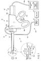
- FIG. 1 The first embodiment is described with reference to FIG. 1 , FIG. 2 , FIG. 3 , FIG. 4A, FIG. 4B, FIG. 4C , FIG. 5A, and FIG. 5B .
- some components are not shown for clarity.
- the surgical system 10 includes an ultrasonic surgical apparatus (hereinafter, surgical apparatus 20) which treats a treatment part 200 such as a living tissue with ultrasonic vibrations, and an electric source unit 90 which generates an electric current for the ultrasonic vibration of the surgical apparatus 20.
- the surgical system 10 further includes a cable 100a which has one end connected to the surgical apparatus 20 and the other end connected to the electric source unit 90 to supply the electric current generated in the electric source unit 90 to the surgical apparatus 20 from the electric source unit 90, and an input unit 110 such as a foot switch, and a water supply unit 120.
- the surgical apparatus 20 includes an ultrasonic vibrator unit (hereinafter, vibrator unit 40) which generates ultrasonic vibrations by the electric current supplied from the electric source unit 90 via the cable 100a, and an ultrasonic probe (hereinafter, probe 51) which is connected to the vibrator unit 40 and which is a transmission member to transmit the ultrasonic vibrations generated in the vibrator unit 40.
- the surgical apparatus 20 further includes a sheath unit 60 into which the probe 51 is inserted, and a treatment portion 70 which is provided at the distal end portion of the probe 51 and which transmits, to the treatment part 200, the ultrasonic vibrations transmitted by the probe 51 and which treats the treatment part 200 with the ultrasonic vibrations.
- the vibrator unit 40 includes an ultrasonic vibrator (hereinafter, vibrator 41) which generates ultrasonic vibrations, and a case 49 which houses the vibrator 41.
- vibrator 41 an ultrasonic vibrator which generates ultrasonic vibrations
- case 49 which houses the vibrator 41.
- the vibrator 41 includes a piezoelectric element 43 which converts the electric current supplied from the electric source unit 90 to ultrasonic vibrations, and a horn 45 which amplifies the amplitude of the ultrasonic vibrations generated in the piezoelectric element 43.
- the piezoelectric element 43 has, for example, a ring-shape, and more than one piezoelectric element 43 is provided.
- the piezoelectric elements 43 are in close contact with one another along the longitudinal axis direction of the vibrator 41.
- the piezoelectric element 43 provided at the distal end portion of the vibrator 41 is connected to the horn 45.
- the piezoelectric element 43 is connected to the cable 100a.
- the horn 45 has, for example, a columnar shape.
- the horn 45 is attached to the case 49 so that a distal end portion of the horn 45 protrudes from the case 49.
- the horn 45 is an amplitude increasing portion which increases the amplitude of ultrasonic vibrations.
- This vibrator 41 is, for example, a bolt-clamped Langevin type transducer (BLT).
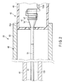
- the probe 51 is formed by an elongated member having a longitudinal axis. This probe 51 has the same thickness as, for example, that of the distal end portion of the horn 45. As shown in FIG. 2 , the probe 51 includes a proximal end portion connected to the distal end portion of the horn 45 (the distal end portion of the vibrator 41), and a distal end portion functioning as a treatment portion 70 which transmits ultrasonic vibrations to the treatment part 200 as shown in FIG. 3 . The ultrasonic vibrations are transmitted to the proximal end portion from the vibrator 41. The ultrasonic vibrations are then transmitted to the distal end portion side of the probe 51 from the proximal end portion of the probe 51.
- the sheath unit 60 includes a sheath 61 through which the probe 51 is inserted, and a holding portion 63 which is provided between the case 49 and the sheath 61 and which is coupled to the case 49 and which holds the sheath 61.
- the sheath 61 has, for example, a cylindrical shape.
- the sheath 61 includes a proximal end portion connected to the holding portion 63 as shown in FIG. 1 , a distal end portion from which the treatment portion 70 serving as the distal end portion of the probe 51 protrudes as shown in FIG. 1 and FIG. 3 , and a grasp member 65 provided at the distal end portion of the sheath 61 as shown in FIG. 1 and FIG. 3 .
- the grasp member 65 is capable of opening and closing relative to the treatment portion 70 in an open-close direction that intersects at right angles with the longitudinal axis direction of the probe 51. As shown in FIG. 3 and FIG. 5A , when the grasp member 65 is closed, the grasp member 65 hold the treatment part 200 together with the treatment portion 70 to grasp the treatment part 200 together with the treatment portion 70. A distal grasp portion is formed by the treatment portion 70 and the grasp member 65.
- the holding portion 63 includes a rotational operation knob 63a which is provided at the distal end portion of the holding portion 63 and which is coupled to the sheath 61, a fixed handle 63b, a movable handle 63c capable of opening and closing relative to the fixed handle 63b, and an opening portion 63d which is provided at the proximal end portion of the holding portion 63 and which is coupled to the case 49.
- the rotational operation knob 63a is rotatable around the axis of the probe 51, and can be coupled to the sheath 61. BY the rotational operation knob 63a coupled to the sheath 61 rotates, the sheath 61 rotates around the axis relative to the probe 51 together with the rotational operation knob 63a.
- the movable handle 63c is attached to the holding portion 63 so that the movable handle 63c is opened and closed relative to the fixed handle 63b.
- the movable handle 63c is coupled to the grasp member 65 by an unshown transmission member.
- This transmission member has a function to transmit an open-close force of the movable handle 63c to the grasp member 65.
- the holding portion 63 has a function of a handle unit to be grasped by a surgeon.
- the electric source unit 90 includes an ultrasonic wave control portion 91a which is connected to the input unit 110 and which controls the electric current for ultrasonic vibrations in accordance with an input amount of the input unit 110.
- the water supply unit 120 includes a reserve portion 121 which is provided outside the surgical apparatus 20 and which reserves a liquid such as physiological saline, and a water supply tube 123 which supplies the liquid reserved in the reserve portion 121.
- the water supply unit 120 also includes a water supply channel 125 which is formed inside the holding portion 63 and between the sheath 61 and the probe 51 and through which the liquid supplied from the water supply tube 123 flows, and a distal end opening portion 127 which id provided at the distal end portion of the sheath 61 to allow the liquid which has flowed through the water supply channel 125 to flow out.
- the water supply unit 120 is provided, for example, along the longitudinal axis of the probe 51.
- the treatment portion 70 protrudes outward from the distal end opening portion 127.
- the reserve portion 121 is connected to the input unit 110.
- the reserve portion 121 controls the supply amount of the liquid in accordance with the input amount of the input unit 110.
- the water supply tube 123 is attached to, for example, a water supply cap 63e provided in the holding portion 63.
- the water supply channel 125 provided inside the sheath 61 and between the probe 51 and the sheath 61 represents the space between the outer circumferential surface of the probe 51 and the inner circumferential surface of the sheath 61 in the diametrical direction of the sheath 61.
- the water supply channel 125 is covered with the sheath 61.
- the distal end opening portion 127 represents the distal end portion of the sheath 61 which is in communication with the outside.
- the water supply unit 120 supplies the liquid reserved in the reserve portion 121 to the surgical apparatus 20 via the water supply tube 123.
- the supplied liquid then flows out from the distal end portion of the sheath 61 (the distal end opening portion 127) through the water supply channel 125 formed between the sheath 61 and the probe 51 of the surgical apparatus 20.
- the liquid is also supplied, for example, to check a bleeding part and to wash the inside of a body cavity.
- ultrasonic treatment ultrasonic vibrations are transmitted to the distal end of the probe 51.
- cavitation is generated in the liquid supplied by the water supply tube 123.
- the treatment part 200 having low elasticity, for example, a hepatic cell is selectively shattered and emulsified by the cavitation.
- the treatment part 200 having high elasticity for example, a blood vessel is not shattered by the cavitation.
- the treatment portion 70 has a linear shape.
- the treatment portion 70 includes the distal end portion of the probe 51 which ultrasonically vibrates.
- the treatment portion 70 is provided at the distal end portion of the probe 51 to protrude outward from the distal end opening portion 127 (the distal end portion of the sheath 61).
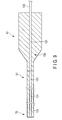
- the treatment portion 70 includes a distal end portion 70a shown in FIG. 3 , a proximal end portion 70b which represents a root of the treatment portion 70 protruding from the sheath 61 (the distal end opening portion 127) as shown in FIG. 3 , and a treatment region 70c which treats the treatment part 200 while the treatment region 70c is in abutment with the treatment part 200 as shown in FIG. 5A and FIG. 5B .
- the treatment region 70c represents the entire circumferential surface of the treatment portion 70 including the distal end portion 70a and the proximal end portion 70b.
- the treatment region 70c represents a region located on the upper surface of the treatment portion 70 facing the grasp member 65.
- This upper surface represents, in the open-close direction, the surface in the close direction, i.e., the surface on the side of the grasp member 65.
- the treatment region 70c represents a region which is covered with the grasp member 65 and faces the grasp member 65 when the grasp member 65 is closed. That is, the treatment region 70c represents an uncoated region 75b described later.
- the open direction of the treatment portion 70 represents the side of the treatment portion 70 which faces and comes closer to the treatment part 200.
- the close direction of the treatment portion 70 represents the side of the treatment portion 70 which faces and comes closer to the grasp member 65.
- the treatment region 70c represents a region which faces, for example, the treatment part 200 and which is located on the lower surface of the distal end portion 70a abutting on the treatment part 200 as shown in FIG. 5B .
- This lower surface represents, in the open-close direction, the surface in the open direction, i.e., the surface on the side of the treatment part 200.
- the treatment region 70c represents a hydrophilic region 75a described later.
- a direction that intersects at right angles with the longitudinal axis direction of the treatment portion 70 and the open-close direction is refereed to as an orthogonal direction.
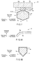
- the treatment portion 70 is tapered in its cross-sectional shape showing a plane direction formed in the open-close direction and the orthogonal direction. More specifically, the treatment portion 70 is tapered off from the grasp member 65 in the open-close direction. In other words, the treatment portion 70 faces the treatment part 200 in the open-close direction, and is tapered from the side of the grasp member 65 to the side of the treatment part 200.
- the treatment portion 70 has the inclined plane 71 which is inclined relative to the orthogonal direction (open-close direction).
- the inclined plane 71 is a counter surface which faces the treatment part 200.
- the inclined plane 71 does not face the grasp member 65.
- the inclined plane 71 represents the lower surface of the treatment portion 70, i.e., the surface of the treatment portion 70 on the side of the open direction.
- the inclined plane 71 is provided between a plane in the orthogonal direction and the longitudinal axis direction where the central axis of the treatment portion 70 is provided, and the treatment part 200.
- an angle formed between a plane 201 which faces the inclined plane 71 and which includes the orthogonal direction and the longitudinal axis direction, and the inclined plane 71 is referred to as an inclination angle ⁇ 1.
- the lower surface of the probe 51 (treatment portion 70) is only composed of a surface having a large inclination angle ⁇ 1
- the surface in which the liquid and the probe 51 contact each other is significantly reduced because the liquid concentrates in the sharp distal end portion. Therefore, the liquid which has flowed out from the distal end opening portion 127 as shown in FIG. 5B easily drops by its weight from the proximal end portion 70b in the open direction (downward) as indicated by an arrow A shown in FIG.
- the lower surface is preferably formed to include a plane (horizontal plane) having an inclination angle ⁇ 1 of 0 degrees as shown in FIG. 4B , and the inclined plane 71 having an inclination angle ⁇ 1 of at least less than 45 degrees, or a smoothly curved surface.
- the treatment portion 70 has the hydrophilic region 75a which is formed by the application of a hydrophilic coat.
- the hydrophilic coat is resistant to a heat of, for example, 200 degrees or more.
- the hydrophilic region 75a prevents the liquid which has flowed out from the distal end opening portion 127 from dropping down by its weight as indicated by the arrow A shown in FIG. 5B , and allows the liquid to drop to the treatment region 70c located on the lower surface of the distal end portion 70a from the distal end opening portion 127 as indicated by an arrow B shown in FIG. 5B .
- the hydrophilic region 75a is linearly provided from the distal end portion 70a to the proximal end portion 70b located in the distal end opening portion 127 along the longitudinal axis direction of the treatment portion 70.
- the hydrophilic region 75a is preferably provided up to the probe 51 covered with the sheath 61.
- the hydrophilic region 75a is provided in at least part of the circumferential surface of the treatment portion 70. More specifically, as shown in FIG. 4A, FIG. 4B, FIG. 4C , and FIG. 5B , the hydrophilic region 75a is provided in the circumferential surface of the treatment portion 70 including the inclined plane 71 and provided in regions except for a region which is covered with the grasp member 65 and faces the grasp member 65 when the grasp member 65 is closed.
- the hydrophilic region 75a has only to be provided in the counter surface which faces the treatment part 200 in the circumferential surface of the treatment portion 70 so that the hydrophilic region 75a is provided in the inclined plane 71.
- the hydrophilic region 75a is included in the treatment region 70c.
- the treatment portion 70 includes the hydrophilic region 75a (coated region), and the uncoated region 75b which is not coated with the hydrophilic coat.
- the uncoated region 75b is the region which is covered with the grasp member 65 and faces the grasp member 65 when the grasp member 65 is closed, the region which the grasp member 65 is fitted to the treatment portion 70.
- the uncoated region 75b is a forbidden region where the application of the hydrophilic coat is forbidden.
- the uncoated region 75b is provided from the distal end portion 70a to the proximal end portion 70b along the longitudinal axis direction of the treatment portion 70.
- the uncoated region 75b is in communication with the hydrophilic region 75a in the circumferential direction of the treatment portion 70.
- the grasp member 65 closes relative to the treatment portion 70 to grasp the treatment part 200 together with the treatment portion 70 as shown in FIG. 5A , and the treatment portion 70 then ultrasonically vibrates.
- the hydrophilic region 75a provided in the uncoated region 75b abuts on the treatment part 200.
- the hydrophilic region 75a ultrasonically vibrates against the treatment part 200 because of the ultrasonic vibrations, rubs against the treatment part 200 because of the ultrasonic vibrations, and is abrases and deteriorates because of heat generated by the friction.
- the same also applies to the case where the hydrophilic region 75a rubs against the grasp member 65 when the hydrophilic region 75a is in abutment with the grasp member 65 as shown in FIG. 4C .
- the uncoated region 75b is provided to prevent damage to the hydrophilic region 75a including abrasion and deterioration.
- the movable handle 63c closes relative to the fixed handle 63b, and the grasp member 65 is closed relative to the treatment portion 70 to grasp the treatment part 200 together with the treatment portion 70 as shown in FIG. 5A .
- the treatment region 70c located on the lower surface of the treatment portion 70 facing the grasp member 65 abuts on the treatment part 200.
- the vibrator 41 When the ultrasonic wave control portion 91a controls an electric current in response to the operation of the input unit 110, the vibrator 41 generates ultrasonic vibrations. The ultrasonic vibrations are transmitted to the treatment portion 70 from the vibrator 41 via the probe 51. In this case, the treatment region 70c is in abutment with the treatment part 200, and transmits the ultrasonic vibrations to the treatment part 200 accordingly.
- This treatment part 200 represents, for example, a blood vessel having high elasticity.
- the uncoated region 75b is provided, the uncoated region 75b is in abutment with the treatment part 200, and the hydrophilic region 75a is not in abutment with the treatment part 200. Therefore, the uncoated region 75b prevents damage to the hydrophilic region 75a including abrasion and deterioration caused by the ultrasonic vibrations.
- the reserve portion 121 supplies the liquid to the water supply tube 123.
- the liquid is supplied, for example, simultaneously with the generation of ultrasonic vibrations by the vibrator 41.
- the liquid flows from the water supply tube 123 to the water supply channel 125, and flows out from the distal end opening portion 127.
- the treatment region 70c located on the lower surface of the distal end portion 70a facing the treatment part 200 abuts on the treatment part 200.
- the liquid drops to the treatment region 70c located on the lower surface of the distal end portion 70a from the distal end opening portion 127 because of the hydrophilic region 75a.
- the liquid does not easily drop down from the proximal end portion 70b as indicated by the arrow A shown in FIG. 5B because of the inclined plane 71, and is urged to drop to the treatment region 70c located on the lower surface of the distal end portion 70a from the distal end opening portion 127 as indicated by the arrow B shown in FIG. 5B .
- the treatment part 200 is selectively shattered and emulsified by the cavitation.
- This treatment part 200 represents, for example, a hepatic cell having low elasticity.
- the hydrophilic region 75a ensures that the liquid can flow to the treatment region 70c without being influenced by the inclination angle ⁇ 2 of the treatment portion 70 relative to the treatment part 200, the protrusion amount of the treatment portion 70 protruding from the distal end opening portion 127, and the distance between the distal end portion 70a and the distal end opening portion 127.
- This treatment region 70c is located on the lower surface of the distal end portion 70a facing the treatment part 200.
- the liquid can flow from the treatment region 70c located on the lower surface of the distal end portion 70a to the treatment part 200 with which the treatment region 70c is in abutment, which makes it possible to prevent any hindrance to the treatment that uses the ultrasonic vibrations.
- the uncoated region 75b can prevent the hydrophilic region 75a from being damaged by ultrasonic vibrations.
- the inclined plane 71 can urge the liquid to drop to the treatment region 70c located on the lower surface of the distal end portion 70a from the distal end opening portion 127.
- the hydrophilic region 75a is provided from the distal end portion 70a to the proximal end portion 70b along the longitudinal axis direction of the treatment portion 70.
- the hydrophilic region 75a is also provided in the circumferential surface of the treatment portion 70 including the inclined plane 71. According to the present embodiment, this ensures that the liquid can flow to the treatment region 70c located on the lower surface of the distal end portion 70a as indicated by the arrow B shown in FIG.
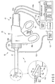
- the surgical apparatus 20 may conduct treatment with a high-frequency current as shown in FIG. 6 .
- the electric source unit 90 further includes a high-frequency current control portion 91b which is connected to the input unit 110 and which controls an electric current for high-frequency waves in accordance with the input amount of the input unit 110.
- the high-frequency current control portion 91b is connected to one end of a cable 100b.
- the other end of the cable 100b is connected to the case 49 and further connected to the vibrator 41.
- electric paths for high-frequency treatment are respectively formed from the electric source unit 90 to the grasp member 65 and the treatment portion 70 via the cable 100a, the vibrator unit 40, the probe 51, and the sheath 61.
- the grasp member 65 includes a grasp body 65a, an electrode member 65b provided in the grasp body 65a, and a pad member 65c provided in the electrode member 65b.
- the grasp body 65a is made of a rigid and electrically conductive material.
- the grasp body 65a is provide at the distal end portion of the sheath 61 to open and close relative to the treatment portion 70 in response to the opening and closing of the movable handle 63c.
- the electrode member 65b is made of a rigid and electrically conductive material.
- the electrode member 65b functions as one electrode of a bipolar electrode for high-frequency treatment.
- the electrode member 65b is provided in the grasp body 65a to face the treatment portion 70.
- the electrode member 65b has a depression portion 65d depressed from the treatment portion 70 toward the grasp body 65a in the open-close direction.
- the depression portion 65d is provided along the longitudinal axis direction of the grasp member 65.
- the depression portion 65d is provided coaxially with the longitudinal axis of the treatment portion 70 in the open-close direction.
- the depression portion 65d faces a flat abutment portion 70d provided on the upper surface of the treatment portion 70.
- the upper surface of the treatment portion 70 represents a surface on the side of the close direction in the open-close direction.
- the electrode member 65b has a pair of electrode receiving surfaces 65e provided on both sides of the depression portion 65d in the width direction of the grasp member 65.
- the electrode receiving surfaces 65e expand in the orthogonal direction (the width direction of the grasp member 65) toward the treatment portion 70 in the open-close direction to cover the upper side of the treatment portion 70.
- the electrode receiving surfaces 65e are respectively provided parallel to electrode surfaces 70e of the treatment portion 70 formed on both sides of the abutment portion 70d of the treatment portion 70 in the orthogonal direction.
- the pad member 65c is made of an insulating biomaterial softer than the probe 51, for example, polytetrafluoroethylene.
- the pad member 65c is fitted in the depression portion 65d. Therefore, the pad member 65c faces the abutment portion 70d of the treatment portion 70.
- the pad member 65c has a flat abutment receiving portion 65f which protrudes from the electrode member 65b toward the treatment portion 70 in the open-close direction and which abuts on the abutment portion 70d of the treatment portion 70 when the grasp member 65 is closed relative to the treatment portion 70.
- the abutment receiving portion 65f has a shape corresponding to the abutment portion 70d of the treatment portion 70.
- the pad member 65c is provided in the electrode member 65b to face the abutment portion 70d of the treatment portion 70, and abuts on the treatment portion 70 when the grasp member 65 is closed relative to the treatment portion 70.
- the electrode surfaces 70e of the treatment portion 70 function as the other electrode of the bipolar electrode for high-frequency treatment.
- the electrode surfaces 70e and the abutment portion 70d of the treatment portion 70 also function as the treatment region 70c.
- the hydrophilic region 75a is provided in the circumferential surface of the treatment portion 70 including the inclined plane 71, and also provided in regions except for a region which is covered with the grasp member 65 and faces the grasp member 65 when the grasp member 65 is closed.
- the hydrophilic region 75a is provided in the regions of the treatment portion 70 except for the electrode surfaces 70e which function as the other electrode of the bipolar electrode and the abutment portion 70d on which the abutment receiving portion 65f of the pad member 65c abuts.
- the uncoated region 75b is provided in the bipolar electrode of the treatment portion 70, i.e., in the electrode surfaces 70e and in the abutment portion 70d on which the abutment receiving portion 65f abuts.
- the hydrophilic region 75a functions as a resistance, which may affect impedance and deteriorate the function of the high-frequency treatment.
- the uncoated region 75b is provided to prevent deterioration of the function of the high-frequency treatment.
- the grasp member 65 closes relative to the treatment portion 70 to grasp the treatment part 200 together with the treatment portion 70 (abutment portion 70d), and the treatment portion 70 then ultrasonically vibrates.
- the hydrophilic region 75a provided in the uncoated region 75b (abutment portion 70d) abuts on the treatment part 200.
- the hydrophilic region 75a ultrasonically vibrates against the treatment part 200 because of the ultrasonic vibrations, rubs against the treatment part 200 because of the ultrasonic vibrations, and is abrase and deteriorates because of heat generated by the friction.
- the same also applies in the case where the hydrophilic region 75a rubs against the grasp member 65 (abutment receiving portion 65f).
- the uncoated region 75b is provided to prevent damage to the hydrophilic region 75a including abrasion and deterioration.
- the movable handle 63c closes relative to the fixed handle 63b, and the grasp member 65 is closed relative to the treatment portion 70.
- the grasp member 65 and the treatment region 70c grasp the treatment part 200.
- the treatment region 70c which represents the electrode surfaces 70e and the abutment portion 70d abuts on the treatment part 200.
- the high-frequency current control portion 91b controls an electric current as a result of the operation of the input unit 110, a high-frequency current is applied to the electrode member 65b and the treatment portion 70.
- the high-frequency current is passed through the treatment part 200 grasped by the grasp member 65 and the treatment portion 70. Consequently, the treatment part 200 is denatured and coagulated.
- advantageous effects similar to the advantageous effects in the first embodiment can also be obtained when the ultrasonic treatment is combined with the high-frequency treatment.
- the uncoated region 75b can prevent deterioration of the function of the high-frequency treatment.
- the treatment portion 70 is curved relative to its longitudinal axis direction, and is asymmetric.
- the hydrophilic region 75a is preferably only provided in the circumferential surface of the treatment portion 70 which is provided outside in the curving direction.
- the treatment portion 70 and the grasp member 65 have a double-door structure capable of opening and closing relative to each other.
- the treatment portion 70 and the grasp member 65 are curved relative to the longitudinal axis direction of the treatment portion 70 as in Modification 2, and are asymmetric.
- the hydrophilic regions 75a are preferably provided in the circumferential surfaces of the treatment portion 70 and the grasp member 65 that are respectively provided outside in the curving direction.
- the surgical apparatus 20 may perform ultrasonic suction.
- the surgical system 10 further includes a suction unit 130.
- the suction unit 130 includes a cavity 131 which is provided inside the probe 51 including the treatment portion 70 and inside the vibrator 41 and which is provided in the longitudinal axis direction of the probe 51, a suction tube 133 which is provided in the case 49 and which is connected to the proximal end portion of the vibrator 41 to communicate with a proximal end portion of the cavity 131, and a suction portion 135 which sucks the resected treatment part 200 and the liquid via the cavity 131 and the suction tube 133.
- a distal end portion of the cavity 131 is provided in the end face of the treatment portion 70, and is open.
- the suction portion 135 includes an unshown suction pump which is connected to the input unit 110 and which is driven in accordance with the input unit 110, and an unshown suction bottle which reserves the sucked treatment part 200 and liquid.
- the suction pump is driven by the operation of the input unit 110, and the treatment part 200 resected by the ultrasonic vibrations and the liquid are sucked from the distal end portion of the cavity 131 and discharged into the suction bottle through the cavity 131 and the suction tube 133.
- the ultrasonic treatment shown in the first embodiment can be combined with the ultrasonic suction treatment.
- the grasp member 65 is provided in the present embodiment, the grasp member 65 may be omitted.
- the hydrophilic region 75a has only to be provided in the entire circumferential surface of the treatment portion 70.
- the uncoated region 75b can be omitted, and the hydrophilic region 75a can be easily provided.
- An examplary surgical apparatus includes:
Landscapes
- Health & Medical Sciences (AREA)
- Life Sciences & Earth Sciences (AREA)
- Engineering & Computer Science (AREA)
- Surgery (AREA)
- Biomedical Technology (AREA)
- Animal Behavior & Ethology (AREA)
- Nuclear Medicine, Radiotherapy & Molecular Imaging (AREA)
- Veterinary Medicine (AREA)
- Public Health (AREA)
- General Health & Medical Sciences (AREA)
- Molecular Biology (AREA)
- Otolaryngology (AREA)
- Medical Informatics (AREA)
- Heart & Thoracic Surgery (AREA)
- Physics & Mathematics (AREA)
- Plasma & Fusion (AREA)
- Surgical Instruments (AREA)
- Radiology & Medical Imaging (AREA)
Claims (4)
- Dispositif ultrasonore chirurgical (20) comprenant :un vibrateur ultrasonore (41) configuré pour générer des vibrations ultrasonores ;une sonde ultrasonore (51) qui possède une partie d'extrémité distale et une partie d'extrémité proximale et qui est connectée au vibrateur ultrasonore (41), et qui est configurée pour transmettre les vibrations ultrasonores générées dans le vibrateur ultrasonore (41) depuis la partie d'extrémité proximale à la partie d'extrémité distale dans une direction d'axe longitudinal de la sonde ultrasonore (51) ;une unité de gaine (60) dans laquelle la sonde ultrasonore (51) est insérée ;un canal d'alimentation en eau (125) qui est fournie à l'intérieur de l'unité de gaine (60) et entre la sonde ultrasonore (51) et l'unité de gaine, et prévu le long de l'axe longitudinal de la sonde ultrasonore (51) et à travers lequel s'écoule un liquide ;une partie d'ouverture (127) d'extrémité distale qui est prévue au niveau d'une partie d'extrémité distale de l'unité de gaine (60) pour permettre au liquide qui s'est écoulé à travers le canal d'alimentation en eau (125) de sortir ; etune partie de traitement (70) qui est prévue au niveau de la partie d'extrémité distale de la sonde ultrasonore (51) pour faire saillie vers l'extérieur depuis la partie d'ouverture (127) d'extrémité distale, qui est configurée pour transmettre les vibrations ultrasonores transmises par la sonde ultrasonore (51) à une partie de traitement (200), et qui est configurée pour traiter la partie de traitement (200) avec les vibrations ultrasonores,dans lequel la partie de traitement (70) comprendune région de traitement (70c) configurée pour traiter la partie de traitement (200) avec le liquide qui s'est écoulé vers l'extérieur depuis la partie d'ouverture (127) d'extrémité distale et avec les vibrations ultrasonores, tandis que la région de traitement (70c) vient en butée contre la partie de traitement (200),
caractérisé en ce que la partie de traitement (70) comprend en outre
une région hydrophile (75a) qui est formée par l'application d'un revêtement hydrophile et qui est prévue dans une partie de la surface circonférentielle de la partie de traitement (70) à prévoir depuis une partie d'extrémité distale (70a) de la région de traitement (70c) à une partie d'extrémité (70b) de la partie de traitement (70) située dans la partie d'ouverture (127) d'extrémité distale dans la direction de l'axe longitudinal. - Dispositif ultrasonore chirurgical (20) selon la revendication 1, dans lequel l'unité de gaine (60) comprend un élément de préhension (65) prévu au niveau de la partie d'extrémité distale de l'unité de gaine (60), l'élément de préhension (65) étant configuré pour s'ouvrir et se fermer par rapport à la partie de traitement (70) dans un sens d'ouverture-fermeture qui croise au niveau des angles droits la direction d'axe longitudinal de la sonde ultrasonore (51), l'élément de préhension (65) étant configuré pour saisir la partie de traitement (200) conjointement avec la partie de traitement (70) lorsqu'il est fermé, et
la partie de traitement (70) comprend en outre une région interdite (75b) qui est couverte par l'élément de préhension (65) lorsque l'élément de préhension (65) est fermé, l'élément de préhension (65) étant adapté à la partie de traitement (70), l'application du revêtement hydrophile étant interdite. - Dispositif ultrasonore chirurgical (20) selon la revendication 1, dans lequel la région hydrophile est prévue dans une surface de compteur qui fait face à la partie de traitement (200) dans la surface circonférentielle de la partie de traitement (70).
- Dispositif ultrasonore chirurgical (20) selon la revendication 1, dans lequel l'unité de gaine (60) comprend un élément de préhension (65) prévu au niveau de la partie d'extrémité distale de l'unité de gaine (60), l'élément de préhension (65) étant configuré pour s'ouvrir et se fermer par rapport à la partie de traitement (70) dans un sens d'ouverture-fermeture qui croise au niveau des angles droits la direction d'axe longitudinal de la sonde ultrasonore (51), l'élément de préhension (65) étant configuré pour saisir la partie de traitement (200) conjointement avec la partie de traitement (70) lorsqu'il est fermé, et
une forme de section de sonde, qui forme la région hydrophile (75a), est configurée pour comprendre une surface incurvée, ou un plan présentant un angle de 45 degrés, ou plus, par rapport au sens d'ouverture-fermeture de l'élément de préhension (65).
Applications Claiming Priority (2)
| Application Number | Priority Date | Filing Date | Title |
|---|---|---|---|
| US201261656143P | 2012-06-06 | 2012-06-06 | |
| PCT/JP2013/065717 WO2013183715A1 (fr) | 2012-06-06 | 2013-06-06 | Dispositif de traitement ultrasonore |
Publications (3)
| Publication Number | Publication Date |
|---|---|
| EP2859859A1 EP2859859A1 (fr) | 2015-04-15 |
| EP2859859A4 EP2859859A4 (fr) | 2015-12-30 |
| EP2859859B1 true EP2859859B1 (fr) | 2016-09-14 |
Family
ID=49712103
Family Applications (1)
| Application Number | Title | Priority Date | Filing Date |
|---|---|---|---|
| EP13800806.5A Active EP2859859B1 (fr) | 2012-06-06 | 2013-06-06 | Dispositif de traitement ultrasonore chirurgical |
Country Status (5)
| Country | Link |
|---|---|
| US (1) | US8905935B2 (fr) |
| EP (1) | EP2859859B1 (fr) |
| JP (1) | JP5485483B1 (fr) |
| CN (1) | CN103889356B (fr) |
| WO (1) | WO2013183715A1 (fr) |
Families Citing this family (10)
| Publication number | Priority date | Publication date | Assignee | Title |
|---|---|---|---|---|
| US20150025517A1 (en) * | 2013-07-18 | 2015-01-22 | Olympus Medical Systems Corp. | Probe and treatment instrument including probe |
| CN105934210B (zh) | 2013-11-26 | 2019-06-11 | 伊西康内外科有限责任公司 | 用于将流体施加到外科器械的超声刀的特征结构 |
| US9743946B2 (en) | 2013-12-17 | 2017-08-29 | Ethicon Llc | Rotation features for ultrasonic surgical instrument |
| KR102420273B1 (ko) * | 2014-05-30 | 2022-07-13 | 어플라이드 메디컬 리소시스 코포레이션 | 조직을 융합시키고 커팅하기 위한 전기수술용 기구 및 전기수술용 발전기 |
| CN106535798B (zh) * | 2014-07-10 | 2019-11-05 | 奥林巴斯株式会社 | 能量处置器具 |
| US10433863B2 (en) | 2014-11-25 | 2019-10-08 | Ethicon Llc | Ultrasonic surgical instrument with blade cooling through retraction |
| US10206705B2 (en) | 2014-11-25 | 2019-02-19 | Ethicon Llc | Features for communication of fluid through shaft assembly of ultrasonic surgical instrument |
| US10004529B2 (en) | 2014-11-25 | 2018-06-26 | Ethicon Llc | Features to drive fluid toward an ultrasonic blade of a surgical instrument |
| WO2017203635A1 (fr) * | 2016-05-25 | 2017-11-30 | オリンパス株式会社 | Dispositif de préhension et de traitement |
| US11039848B2 (en) | 2016-11-16 | 2021-06-22 | Cilag Gmbh International | Surgical instrument with spot coagulation control and algorithm |
Citations (1)
| Publication number | Priority date | Publication date | Assignee | Title |
|---|---|---|---|---|
| US20090030439A1 (en) * | 2007-07-27 | 2009-01-29 | Stulen Foster B | Ultrasonic surgical instruments |
Family Cites Families (8)
| Publication number | Priority date | Publication date | Assignee | Title |
|---|---|---|---|---|
| US5454373A (en) * | 1994-07-20 | 1995-10-03 | Boston Scientific Corporation | Medical acoustic imaging |
| JP2000023994A (ja) * | 1998-07-16 | 2000-01-25 | Olympus Optical Co Ltd | 超音波処置装置 |
| US5807310A (en) * | 1997-05-13 | 1998-09-15 | Nexus Medical System, Inc. Llc | Irrigation sleeve for an ultrasonic tip |
| US6953461B2 (en) * | 2002-05-16 | 2005-10-11 | Tissuelink Medical, Inc. | Fluid-assisted medical devices, systems and methods |
| US6875220B2 (en) * | 2002-12-30 | 2005-04-05 | Cybersonics, Inc. | Dual probe |
| JP3840194B2 (ja) | 2003-04-07 | 2006-11-01 | キヤノン株式会社 | 振動ナイフ |
| WO2009018075A1 (fr) * | 2007-07-27 | 2009-02-05 | Ethicon Endo-Surgery, Inc | Instruments chirurgicaux à ultrasons |
| US8348967B2 (en) | 2007-07-27 | 2013-01-08 | Ethicon Endo-Surgery, Inc. | Ultrasonic surgical instruments |
-
2013
- 2013-06-06 EP EP13800806.5A patent/EP2859859B1/fr active Active
- 2013-06-06 WO PCT/JP2013/065717 patent/WO2013183715A1/fr not_active Ceased
- 2013-06-06 JP JP2013555667A patent/JP5485483B1/ja active Active
- 2013-06-06 CN CN201380003544.7A patent/CN103889356B/zh active Active
- 2013-12-31 US US14/145,379 patent/US8905935B2/en active Active
Patent Citations (1)
| Publication number | Priority date | Publication date | Assignee | Title |
|---|---|---|---|---|
| US20090030439A1 (en) * | 2007-07-27 | 2009-01-29 | Stulen Foster B | Ultrasonic surgical instruments |
Also Published As
| Publication number | Publication date |
|---|---|
| CN103889356B (zh) | 2016-05-18 |
| WO2013183715A1 (fr) | 2013-12-12 |
| EP2859859A1 (fr) | 2015-04-15 |
| EP2859859A4 (fr) | 2015-12-30 |
| JP5485483B1 (ja) | 2014-05-07 |
| US8905935B2 (en) | 2014-12-09 |
| JPWO2013183715A1 (ja) | 2016-02-01 |
| CN103889356A (zh) | 2014-06-25 |
| US20140188014A1 (en) | 2014-07-03 |
Similar Documents
| Publication | Publication Date | Title |
|---|---|---|
| EP2859859B1 (fr) | Dispositif de traitement ultrasonore chirurgical | |
| JP6307669B1 (ja) | 高周波処置具 | |
| EP2591734B1 (fr) | Dispositif d'émission de liquide | |
| EP4014902B1 (fr) | Instrument chirurgical doté d'un effecteur terminal à deux modes et levier composé doté de détentes | |
| EP2484301B1 (fr) | Dispositif de traitement par les ultrasons | |
| KR102549644B1 (ko) | 열 감소 특징부를 가진 초음파 수술 기구 블레이드 | |
| US8672935B2 (en) | Ultrasound treatment system | |
| EP3167831B1 (fr) | Unité et outil de traitement d'énergie | |
| US20200107853A1 (en) | Ultrasonic surgical instrument with cooling conduit | |
| EP2636382B1 (fr) | Sonde ultrasonique | |
| US20210128226A1 (en) | Treatment instrument and treatment system | |
| EP2601901B1 (fr) | Dispositif de traitement par ultrasons | |
| CN108289694B (zh) | 提供超声组织乳化和超声剪切的外科器械 | |
| EP3478191B1 (fr) | Instrument chirurgical ultrasonique avec élément de serrage déformant | |
| CN103458815B (zh) | 超声波探头及超声波处理装置 | |
| EP3457960B1 (fr) | Éléments de dissection passive pour instrument chirurgical à ultrasons | |
| JP3826141B2 (ja) | 超音波切開凝固装置 |
Legal Events
| Date | Code | Title | Description |
|---|---|---|---|
| PUAI | Public reference made under article 153(3) epc to a published international application that has entered the european phase |
Free format text: ORIGINAL CODE: 0009012 |
|
| 17P | Request for examination filed |
Effective date: 20141211 |
|
| AK | Designated contracting states |
Kind code of ref document: A1 Designated state(s): AL AT BE BG CH CY CZ DE DK EE ES FI FR GB GR HR HU IE IS IT LI LT LU LV MC MK MT NL NO PL PT RO RS SE SI SK SM TR |
|
| AX | Request for extension of the european patent |
Extension state: BA ME |
|
| DAX | Request for extension of the european patent (deleted) | ||
| RAP1 | Party data changed (applicant data changed or rights of an application transferred) |
Owner name: OLYMPUS CORPORATION |
|
| RA4 | Supplementary search report drawn up and despatched (corrected) |
Effective date: 20151202 |
|
| RIC1 | Information provided on ipc code assigned before grant |
Ipc: A61B 18/00 20060101AFI20151126BHEP |
|
| GRAP | Despatch of communication of intention to grant a patent |
Free format text: ORIGINAL CODE: EPIDOSNIGR1 |
|
| INTG | Intention to grant announced |
Effective date: 20160317 |
|
| GRAS | Grant fee paid |
Free format text: ORIGINAL CODE: EPIDOSNIGR3 |
|
| GRAA | (expected) grant |
Free format text: ORIGINAL CODE: 0009210 |
|
| RIN1 | Information on inventor provided before grant (corrected) |
Inventor name: AKAGANE, TSUNETAKA |
|
| RAP1 | Party data changed (applicant data changed or rights of an application transferred) |
Owner name: OLYMPUS CORPORATION |
|
| AK | Designated contracting states |
Kind code of ref document: B1 Designated state(s): AL AT BE BG CH CY CZ DE DK EE ES FI FR GB GR HR HU IE IS IT LI LT LU LV MC MK MT NL NO PL PT RO RS SE SI SK SM TR |
|
| REG | Reference to a national code |
Ref country code: GB Ref legal event code: FG4D |
|
| REG | Reference to a national code |
Ref country code: CH Ref legal event code: EP |
|
| RAP2 | Party data changed (patent owner data changed or rights of a patent transferred) |
Owner name: OLYMPUS CORPORATION |
|
| RAP2 | Party data changed (patent owner data changed or rights of a patent transferred) |
Owner name: OLYMPUS CORPORATION |
|
| REG | Reference to a national code |
Ref country code: IE Ref legal event code: FG4D |
|
| REG | Reference to a national code |
Ref country code: AT Ref legal event code: REF Ref document number: 828049 Country of ref document: AT Kind code of ref document: T Effective date: 20161015 |
|
| REG | Reference to a national code |
Ref country code: DE Ref legal event code: R096 Ref document number: 602013011721 Country of ref document: DE |
|
| REG | Reference to a national code |
Ref country code: LT Ref legal event code: MG4D |
|
| REG | Reference to a national code |
Ref country code: NL Ref legal event code: MP Effective date: 20160914 |
|
| PG25 | Lapsed in a contracting state [announced via postgrant information from national office to epo] |
Ref country code: RS Free format text: LAPSE BECAUSE OF FAILURE TO SUBMIT A TRANSLATION OF THE DESCRIPTION OR TO PAY THE FEE WITHIN THE PRESCRIBED TIME-LIMIT Effective date: 20160914 Ref country code: HR Free format text: LAPSE BECAUSE OF FAILURE TO SUBMIT A TRANSLATION OF THE DESCRIPTION OR TO PAY THE FEE WITHIN THE PRESCRIBED TIME-LIMIT Effective date: 20160914 Ref country code: LT Free format text: LAPSE BECAUSE OF FAILURE TO SUBMIT A TRANSLATION OF THE DESCRIPTION OR TO PAY THE FEE WITHIN THE PRESCRIBED TIME-LIMIT Effective date: 20160914 Ref country code: FI Free format text: LAPSE BECAUSE OF FAILURE TO SUBMIT A TRANSLATION OF THE DESCRIPTION OR TO PAY THE FEE WITHIN THE PRESCRIBED TIME-LIMIT Effective date: 20160914 Ref country code: NO Free format text: LAPSE BECAUSE OF FAILURE TO SUBMIT A TRANSLATION OF THE DESCRIPTION OR TO PAY THE FEE WITHIN THE PRESCRIBED TIME-LIMIT Effective date: 20161214 |
|
| REG | Reference to a national code |
Ref country code: AT Ref legal event code: MK05 Ref document number: 828049 Country of ref document: AT Kind code of ref document: T Effective date: 20160914 |
|
| PG25 | Lapsed in a contracting state [announced via postgrant information from national office to epo] |
Ref country code: GR Free format text: LAPSE BECAUSE OF FAILURE TO SUBMIT A TRANSLATION OF THE DESCRIPTION OR TO PAY THE FEE WITHIN THE PRESCRIBED TIME-LIMIT Effective date: 20161215 Ref country code: LV Free format text: LAPSE BECAUSE OF FAILURE TO SUBMIT A TRANSLATION OF THE DESCRIPTION OR TO PAY THE FEE WITHIN THE PRESCRIBED TIME-LIMIT Effective date: 20160914 Ref country code: NL Free format text: LAPSE BECAUSE OF FAILURE TO SUBMIT A TRANSLATION OF THE DESCRIPTION OR TO PAY THE FEE WITHIN THE PRESCRIBED TIME-LIMIT Effective date: 20160914 Ref country code: SE Free format text: LAPSE BECAUSE OF FAILURE TO SUBMIT A TRANSLATION OF THE DESCRIPTION OR TO PAY THE FEE WITHIN THE PRESCRIBED TIME-LIMIT Effective date: 20160914 |
|
| PG25 | Lapsed in a contracting state [announced via postgrant information from national office to epo] |
Ref country code: EE Free format text: LAPSE BECAUSE OF FAILURE TO SUBMIT A TRANSLATION OF THE DESCRIPTION OR TO PAY THE FEE WITHIN THE PRESCRIBED TIME-LIMIT Effective date: 20160914 Ref country code: RO Free format text: LAPSE BECAUSE OF FAILURE TO SUBMIT A TRANSLATION OF THE DESCRIPTION OR TO PAY THE FEE WITHIN THE PRESCRIBED TIME-LIMIT Effective date: 20160914 |
|
| PG25 | Lapsed in a contracting state [announced via postgrant information from national office to epo] |
Ref country code: AT Free format text: LAPSE BECAUSE OF FAILURE TO SUBMIT A TRANSLATION OF THE DESCRIPTION OR TO PAY THE FEE WITHIN THE PRESCRIBED TIME-LIMIT Effective date: 20160914 Ref country code: PT Free format text: LAPSE BECAUSE OF FAILURE TO SUBMIT A TRANSLATION OF THE DESCRIPTION OR TO PAY THE FEE WITHIN THE PRESCRIBED TIME-LIMIT Effective date: 20170116 Ref country code: CZ Free format text: LAPSE BECAUSE OF FAILURE TO SUBMIT A TRANSLATION OF THE DESCRIPTION OR TO PAY THE FEE WITHIN THE PRESCRIBED TIME-LIMIT Effective date: 20160914 Ref country code: ES Free format text: LAPSE BECAUSE OF FAILURE TO SUBMIT A TRANSLATION OF THE DESCRIPTION OR TO PAY THE FEE WITHIN THE PRESCRIBED TIME-LIMIT Effective date: 20160914 Ref country code: PL Free format text: LAPSE BECAUSE OF FAILURE TO SUBMIT A TRANSLATION OF THE DESCRIPTION OR TO PAY THE FEE WITHIN THE PRESCRIBED TIME-LIMIT Effective date: 20160914 Ref country code: SM Free format text: LAPSE BECAUSE OF FAILURE TO SUBMIT A TRANSLATION OF THE DESCRIPTION OR TO PAY THE FEE WITHIN THE PRESCRIBED TIME-LIMIT Effective date: 20160914 Ref country code: IS Free format text: LAPSE BECAUSE OF FAILURE TO SUBMIT A TRANSLATION OF THE DESCRIPTION OR TO PAY THE FEE WITHIN THE PRESCRIBED TIME-LIMIT Effective date: 20170114 Ref country code: SK Free format text: LAPSE BECAUSE OF FAILURE TO SUBMIT A TRANSLATION OF THE DESCRIPTION OR TO PAY THE FEE WITHIN THE PRESCRIBED TIME-LIMIT Effective date: 20160914 Ref country code: BE Free format text: LAPSE BECAUSE OF FAILURE TO SUBMIT A TRANSLATION OF THE DESCRIPTION OR TO PAY THE FEE WITHIN THE PRESCRIBED TIME-LIMIT Effective date: 20160914 Ref country code: BG Free format text: LAPSE BECAUSE OF FAILURE TO SUBMIT A TRANSLATION OF THE DESCRIPTION OR TO PAY THE FEE WITHIN THE PRESCRIBED TIME-LIMIT Effective date: 20161214 |
|
| REG | Reference to a national code |
Ref country code: DE Ref legal event code: R097 Ref document number: 602013011721 Country of ref document: DE |
|
| PG25 | Lapsed in a contracting state [announced via postgrant information from national office to epo] |
Ref country code: IT Free format text: LAPSE BECAUSE OF FAILURE TO SUBMIT A TRANSLATION OF THE DESCRIPTION OR TO PAY THE FEE WITHIN THE PRESCRIBED TIME-LIMIT Effective date: 20160914 |
|
| PLBE | No opposition filed within time limit |
Free format text: ORIGINAL CODE: 0009261 |
|
| STAA | Information on the status of an ep patent application or granted ep patent |
Free format text: STATUS: NO OPPOSITION FILED WITHIN TIME LIMIT |
|
| PG25 | Lapsed in a contracting state [announced via postgrant information from national office to epo] |
Ref country code: DK Free format text: LAPSE BECAUSE OF FAILURE TO SUBMIT A TRANSLATION OF THE DESCRIPTION OR TO PAY THE FEE WITHIN THE PRESCRIBED TIME-LIMIT Effective date: 20160914 |
|
| 26N | No opposition filed |
Effective date: 20170615 |
|
| PG25 | Lapsed in a contracting state [announced via postgrant information from national office to epo] |
Ref country code: SI Free format text: LAPSE BECAUSE OF FAILURE TO SUBMIT A TRANSLATION OF THE DESCRIPTION OR TO PAY THE FEE WITHIN THE PRESCRIBED TIME-LIMIT Effective date: 20160914 |
|
| PG25 | Lapsed in a contracting state [announced via postgrant information from national office to epo] |
Ref country code: MC Free format text: LAPSE BECAUSE OF FAILURE TO SUBMIT A TRANSLATION OF THE DESCRIPTION OR TO PAY THE FEE WITHIN THE PRESCRIBED TIME-LIMIT Effective date: 20160914 |
|
| REG | Reference to a national code |
Ref country code: CH Ref legal event code: PL |
|
| GBPC | Gb: european patent ceased through non-payment of renewal fee |
Effective date: 20170606 |
|
| REG | Reference to a national code |
Ref country code: IE Ref legal event code: MM4A |
|
| REG | Reference to a national code |
Ref country code: FR Ref legal event code: ST Effective date: 20180228 |
|
| PG25 | Lapsed in a contracting state [announced via postgrant information from national office to epo] |
Ref country code: IE Free format text: LAPSE BECAUSE OF NON-PAYMENT OF DUE FEES Effective date: 20170606 Ref country code: GB Free format text: LAPSE BECAUSE OF NON-PAYMENT OF DUE FEES Effective date: 20170606 Ref country code: CH Free format text: LAPSE BECAUSE OF NON-PAYMENT OF DUE FEES Effective date: 20170630 Ref country code: LI Free format text: LAPSE BECAUSE OF NON-PAYMENT OF DUE FEES Effective date: 20170630 Ref country code: LU Free format text: LAPSE BECAUSE OF NON-PAYMENT OF DUE FEES Effective date: 20170606 |
|
| PG25 | Lapsed in a contracting state [announced via postgrant information from national office to epo] |
Ref country code: FR Free format text: LAPSE BECAUSE OF NON-PAYMENT OF DUE FEES Effective date: 20170630 |
|
| PG25 | Lapsed in a contracting state [announced via postgrant information from national office to epo] |
Ref country code: MT Free format text: LAPSE BECAUSE OF NON-PAYMENT OF DUE FEES Effective date: 20170606 |
|
| PG25 | Lapsed in a contracting state [announced via postgrant information from national office to epo] |
Ref country code: AL Free format text: LAPSE BECAUSE OF FAILURE TO SUBMIT A TRANSLATION OF THE DESCRIPTION OR TO PAY THE FEE WITHIN THE PRESCRIBED TIME-LIMIT Effective date: 20160914 |
|
| PG25 | Lapsed in a contracting state [announced via postgrant information from national office to epo] |
Ref country code: HU Free format text: LAPSE BECAUSE OF FAILURE TO SUBMIT A TRANSLATION OF THE DESCRIPTION OR TO PAY THE FEE WITHIN THE PRESCRIBED TIME-LIMIT; INVALID AB INITIO Effective date: 20130606 |
|
| PG25 | Lapsed in a contracting state [announced via postgrant information from national office to epo] |
Ref country code: CY Free format text: LAPSE BECAUSE OF FAILURE TO SUBMIT A TRANSLATION OF THE DESCRIPTION OR TO PAY THE FEE WITHIN THE PRESCRIBED TIME-LIMIT Effective date: 20160914 |
|
| PG25 | Lapsed in a contracting state [announced via postgrant information from national office to epo] |
Ref country code: MK Free format text: LAPSE BECAUSE OF FAILURE TO SUBMIT A TRANSLATION OF THE DESCRIPTION OR TO PAY THE FEE WITHIN THE PRESCRIBED TIME-LIMIT Effective date: 20160914 |
|
| PG25 | Lapsed in a contracting state [announced via postgrant information from national office to epo] |
Ref country code: TR Free format text: LAPSE BECAUSE OF FAILURE TO SUBMIT A TRANSLATION OF THE DESCRIPTION OR TO PAY THE FEE WITHIN THE PRESCRIBED TIME-LIMIT Effective date: 20160914 |
|
| P01 | Opt-out of the competence of the unified patent court (upc) registered |
Effective date: 20230528 |
|
| PGFP | Annual fee paid to national office [announced via postgrant information from national office to epo] |
Ref country code: DE Payment date: 20250618 Year of fee payment: 13 |