EP2859925A2 - Couplage pour trains miniatures et modélisme - Google Patents
Couplage pour trains miniatures et modélisme Download PDFInfo
- Publication number
- EP2859925A2 EP2859925A2 EP20140181536 EP14181536A EP2859925A2 EP 2859925 A2 EP2859925 A2 EP 2859925A2 EP 20140181536 EP20140181536 EP 20140181536 EP 14181536 A EP14181536 A EP 14181536A EP 2859925 A2 EP2859925 A2 EP 2859925A2
- Authority
- EP
- European Patent Office
- Prior art keywords
- holding element
- coupling
- receiving shaft
- movable holding
- movable
- Prior art date
- Legal status (The legal status is an assumption and is not a legal conclusion. Google has not performed a legal analysis and makes no representation as to the accuracy of the status listed.)
- Granted
Links
Images



Classifications
-
- A—HUMAN NECESSITIES
- A63—SPORTS; GAMES; AMUSEMENTS
- A63H—TOYS, e.g. TOPS, DOLLS, HOOPS OR BUILDING BLOCKS
- A63H19/00—Model railways
- A63H19/16—Parts for model railway vehicles
- A63H19/18—Car coupling or uncoupling mechanisms
Definitions
- the present invention relates to a coupling, in particular hook coupling, for electric play and model trains according to the preamble of claim 1. Furthermore, the present invention relates to an electric motor drive for a corresponding coupling according to the preamble of claim 13.
- the NEM 362 For accommodating exchangeable coupling heads of nominal size H0, there are e.g. the NEM 362, for the inclusion of exchangeable coupling heads of size N, the NEM 355. These measures make it possible to combine the coupling heads of the desired model railroad manufacturer with other manufacturer's model railroad vehicles and thus to use model railroad vehicles universally.
- Model railway vehicles can be decoupled in various ways. On the one hand, model railway vehicles can be decoupled manually, which is sometimes difficult considering the scale reduction is. Furthermore, there are so-called uncoupling ramps, operated in the region of which clutches and thereby the decoupling process can be initiated. In recent times, motor or magnetically actuated clutches have been added, by means of which it is possible to carry out a decoupling process location-independent via the remote control.
- a coupling according to the preamble of claim 1 is known.
- the coupling is intended to be mounted with its mounting projection on a standard receiving shaft of different model train manufacturers.
- the movable holding element, on the front side of which the hook is located, extends in the rear region thereof below the vehicle-side receiving shaft.
- a hook pressure plate is attached via a hinge directly to an eyelet and provided with a drawbar.
- the clutch can be operated by means of a magnet, servomotor or geared motor.
- a jaw clutch for electric play and model trains is known in which the coupling head of the mating coupling part is provided with a foot part, which serves for insertion into standardized receiving slots.
- the coupling head comprises a fork-like foot part with protruding ends, which engage around the rear end of the receiving shaft in a latching manner.
- a model railway vehicle with a receiving shaft for a coupling head which has a fork-shaped mounting projection.
- the receiving shaft is connected via an elastically flexible connecting web made of plastic with the vehicle frame.
- the object of the present invention is to provide a novel coupling of the type mentioned above, with which the possible applications can be extended in a structurally simple manner.
- the movable holding element is configured such that it extends through the receiving shaft or on the outside (eg., Below the receiving shaft) along the receiving shaft and the rear end portion of the movable Retaining element projects beyond the rear end of the receiving shaft.
- This makes it possible to control the coupling via the movable retaining element on the back of the receiving shaft by means of a preferably motorized drive via a driver.
- This activation can advantageously take place in such a way that the driver preferably acts on the movable holding element without a mounting connection, so that to remove the coupling, it only has to be unlocked on the receiving shaft and pulled out of the latter. It is therefore no time-consuming disassembly z. B. by desoldering or disassembly necessary.
- the movable support member also extend beyond the receiving shaft to the rear and project beyond the rear end of the receiving shaft with its end, for example, when the movable support member with an additional z. B. finger-like projection is formed.
- the rear end region of the movable holding element in front of the rear end of the receiving shaft mechanically, preferably loosely only by means of a stop, ie without a mounting connection.
- the receiving shaft is also available for receiving the movable holding element or at least a part thereof.
- the rear end region of the movable holding element expediently interacts with a driver operatively connected to the driver.
- the movable holding element associated region of the driver is preferably a mouth, in which the rear end portion 7 of the movable support member 3 loosely and preferably also transversely displaceable engages.
- the pivot axis A of the movable support member is located within the receiving shaft. This has the advantage that a high degree of miniaturization can be turned on and a simple construction can be selected to ensure pivotability, since the receiving shaft at the same time ensures that the movable holding element remains in position, ie can not fall out.
- the construction also has the advantage that a loose control of the movable holding element can be done on the back of the receiving shaft and that for example by a simple axial movement of a corresponding actuating element.
- a loose control of the movable holding element can be done on the back of the receiving shaft and that for example by a simple axial movement of a corresponding actuating element.
- a one-sided or double-sided loose stop of a, for example, vertically actuatable actuating element can take place.
- the construction can be considerably simplified.
- this structural measure allows for horizontal pivoting of the clutch z. B. when cornering the movable support member also pivoted transversely to the stop but nevertheless still held in the attack.
- the stop or the driver is provided for this purpose in each case with a flat stop surface along which the end of the movable holding element can move in the condition of the stop.
- the receiving shaft is a so-called standard receiving shaft for replaceable coupling heads.
- the mounting projection of the coupling according to the invention is expediently fork-shaped, wherein the movable holding element is located between the two fork projections of the mounting projection.
- the movable holding element does not interfere. Furthermore, it is protected against external influences.
- the mounting projection has latching projections which engage the rear of the receiving shaft, whereby the mounting projection is insertable into the receiving shaft, snaps into the intended position and thus a positional fixation is achieved.
- the movable holding element has at least one recess. This serves to ensure sufficient mobility of the movable holding element in the installed state.
- the recess or at least a part thereof is located in front of the axis of rotation A but within the receiving shaft. As a result, the dimensions of the coupling can be reduced.
- the axis of rotation A can be ensured by mutually contacting recesses or projections.
- the axis of rotation A is formed on the movable or rigid holding element by a projection on the rigid holding element and a corresponding recess on the movable holding element or vice versa.
- the open side of the recess is directed to the top or bottom of the coupling. Nevertheless, cohesion of construction through the receiving shaft occurs.
- a clip may be provided which hold together the rigid and movable holding element.
- the movable and rigid holding element can also be previously fixed by a bolt.
- a hook preferably an upward hook
- the present invention further relates to an electric motor drive for a clutch, preferably according to a clutch according to one of claims 1-12.
- the drive comprises an electric drive motor with drive shaft and a threaded screw which is connected to the drive shaft. Furthermore, a movably mounted threaded sleeve is provided, which receives the threaded screw and is connected to a driver for actuating a movable holding element of a coupling. This makes it possible to easily transmit the movement generated by the electric drive motor in a translational movement in confined spaces.
- the driver is movable back and forth in the longitudinal direction of the axis of the drive shaft of the electric drive motor.
- the driver can also be reciprocated in a direction obliquely or transversely to the axis of the drive shaft of the electric drive motor. In both cases, it is a simple structural design.
- micromotor or micro-servomotor is used as the electric drive motor.
- Micromotors are manufactured and sold in large quantities as standard parts.
- the driver is provided with a jaw, by means of which the movable holding element is detected in the region of its rear end region and can be moved in both directions.
- the driver is articulated.
- the arrangement consisting of an electric drive motor, a threaded screw and a threaded sleeve can be positioned horizontally positioned in the model vehicle.
- Fig. 1A shows a useful embodiment of the coupling according to the invention in plan view. It comprises a rigid retaining element 2, which has a projection 1, which serves the coupling in an in Fig. 1A
- the projection 1 is fork-shaped by having a first fork projection 8 and second fork projection 9, at its free ends in each case a latching projection 10 and 11 is located.
- the clutch is thus able to be accommodated in a so-called Norm receiving shaft.
- the latching projections 10 and 11 engage around the rear area of the receiving shaft 4 (eg. Fig. 2A ) and lock it accordingly.
- the region of the rigid holding element 2 located outside the receiving shaft has an expanded shape, at the front end of which a coupling yoke 20 is located.
- a movable support member 3 In the interior formed by the rigid support member 2 is a movable support member 3, at the end of a preferably provided with an outside bevel hook 5 is located.
- the hook 5 serves to the preferably slightly curved coupling bracket 20 of the coupling of the adjacent vehicle behind.
- the movable support member 3 is preferably formed elongated and extends beyond the rear end of the mounting projection 1.
- the movable support member 3 is thus with its rear end portion 7 outside of the receiving shaft 4 via.
- the pivot axis of the movable support member 3 is located to the rigid support member 2 in the designated by the letter A area.
- the position of the pivot axis A is particularly clear from the illustration according to Fig. 1B ,
- the movable holding element 3 has in the region between the pivot axis A and the rear end region 7, a recess 6, which ensures sufficient mobility of the receiving shaft passing, movable support member 3.
- the rigid support member 2 has a projection 13 with a curved surface which cooperates with a corresponding recess 12 on the movable support member 3, so that the movable support member 3, as shown in FIG Fig. 1B can be pivoted from the dome position shown there by pivoting the rear end portion 7 to a pivoting radius made possible by the recess 6 upwards. As a result, the clutch is brought into a decoupled position.
- the movable holding element is only according to the in Fig. 1B shown arrangement from below and the two holding elements 2, 3 then jointly inserted into the receiving shaft 4.
- the receiving shaft 4 thereby holds both holding elements 2, 3 to each other in position.
- the receiving shaft 4 simultaneously limits the pivoting movement of the movable holding element 3 via a in the Fig. 1 B clutch position shown upward.
- the rear end portion 7 of the movable support member 3 is provided with an inclined surface 14, which serves in a loose stop with a (eg in Fig. 2A shown) mouth loosely in contact.
- a (eg in Fig. 2A shown) mouth loosely in contact is provided.
- the coupling shown merely consists of two parts, which can be produced in a simple manner either from plastic or metal.
- the rigid support member 2 may be designed as a plastic part and the movable support member 3 as a metal part.
- the novel coupling impresses with its simplicity and the small space requirement.
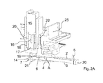
- Fig. 2A is the coupling according to the embodiment according to Fig. 1A and 1B in the installed state shown in coupled position.
- the reference numeral 4 denotes a receiving shaft, which is open at the front and rear and is fixed by means of an anchor 22 in the body 25 of the model vehicle.
- the anchoring 22 also ensures the pivot point of the standard shaft 4.
- an electric drive motor 15, preferably a so-called micromotor housed in a vertical orientation in the structure 25 of the model vehicle.
- the drive motor 15 has a drive shaft 16 which is fixedly connected to a threaded screw 17.
- the rotational movement of the screw 17 is received by a threaded sleeve 18, which in turn is fixedly connected to a driver 19.
- the driver 19 moves either up or down.
- the drive motor 15 or its control recognizes the end positions of the driver 19.
- a mouth 21 in which the rear end portion 7 of the movable holding member 3 loosely engages.
- a special feature of the present invention is that the clutch can be removed in the mounted state despite activation by means of an electric motor drive only by decoupling the mounting projection 1 from the receiving shaft 4.
- the construction according to the invention makes it possible to introduce a different type of coupling from another manufacturer, if necessary, into the receiving shaft. This ensures that the model railway vehicles provided with a respective drive can nonetheless be operated with different types of clutches.
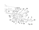
- the Fig. 3A and Figure 3B shows an alternative embodiment of the present invention.
- the drive motor 15 is in the structure 25 of the model railway vehicle in a horizontal position.
- the driver 19 is articulated by a hinge point 23, so that upon appropriate actuation of the drive motor 15, the mouth 21 of the driver 19 moves due to the pivoting of the driver 19 about the pivot point 23 either up or down.
- a corresponding free space 24 is also in the embodiment of the Fig. 2A and 2B available.
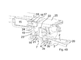
- the movable holding member 3 is fork-shaped. It comprises a first region 3a of the movable holding element 3, which runs backwards along the underside of the receiving shaft 4 and projects beyond the rear end of the receiving shaft 4 with its rear end region 7.
- the further, second region 3b of the movable holding element 3 is preferably located within the receiving shaft 4, where the pivot point A is located. Otherwise, the embodiments differ according to Fig. 3 and 4 Not.
- the present invention makes it possible to provide a motor-driven clutch in a simple manner, while at the same time it remains possible to exchange the relevant clutch for a clutch from another manufacturer. As a result, a very high versatility is achieved.
Landscapes
- Toys (AREA)
Applications Claiming Priority (1)
| Application Number | Priority Date | Filing Date | Title |
|---|---|---|---|
| DE102013111207.2A DE102013111207B4 (de) | 2013-10-10 | 2013-10-10 | Kupplung für elektrische Spiel- und Modellbahnen |
Publications (4)
| Publication Number | Publication Date |
|---|---|
| EP2859925A2 true EP2859925A2 (fr) | 2015-04-15 |
| EP2859925A3 EP2859925A3 (fr) | 2015-08-05 |
| EP2859925B1 EP2859925B1 (fr) | 2018-05-02 |
| EP2859925B9 EP2859925B9 (fr) | 2018-11-28 |
Family
ID=51383595
Family Applications (1)
| Application Number | Title | Priority Date | Filing Date |
|---|---|---|---|
| EP14181536.5A Active EP2859925B9 (fr) | 2013-10-10 | 2014-08-20 | Couplage pour trains miniatures et modélisme |
Country Status (2)
| Country | Link |
|---|---|
| EP (1) | EP2859925B9 (fr) |
| DE (1) | DE102013111207B4 (fr) |
Citations (3)
| Publication number | Priority date | Publication date | Assignee | Title |
|---|---|---|---|---|
| DE3939528C1 (en) | 1989-11-30 | 1990-09-13 | Gebr. Fleischmann, 8500 Nuernberg, De | Model railway claw coupling - incorporates remote-controlled release incorporating wedge-shaped tongue |
| DE202004010913U1 (de) | 2004-07-11 | 2004-09-30 | Fertig, Kai | Funktionsfähige automatische Entkupplung für Öse-Haken-Modellbahnkupplung Spur I + II |
| AT501445A1 (de) | 2005-02-07 | 2006-09-15 | Maegdefrau Peter Dipl Wirt Ing | Modellbahnfahrzeug |
Family Cites Families (7)
| Publication number | Priority date | Publication date | Assignee | Title |
|---|---|---|---|---|
| DE3203639C2 (de) * | 1982-02-03 | 1986-01-16 | Gebr. Fleischmann, 8500 Nürnberg | Kupplung für elektrische Spiel- und Modellbahnen |
| GB2243723B (en) * | 1990-05-04 | 1994-08-24 | Teppei Kumada | Electromagnetic actuating device |
| DE4302970C1 (de) * | 1993-02-03 | 1994-06-01 | Lehmann E P Patentwerk | Ferngesteuerte Kupplung für elektrische Spiel- und Modellbahnen |
| US5775524A (en) * | 1996-03-25 | 1998-07-07 | Kadee Quality Products Co. | Remote uncoupling mechanism |
| KR20030073135A (ko) * | 2002-03-08 | 2003-09-19 | 주식회사 삼홍사 | 모형기차의 커플러 |
| DE102005005730A1 (de) * | 2005-02-09 | 2006-08-24 | Brawa Artur Braun Modellspielwarenfabrik Gmbh + Co. | Hakenkupplung, Lokomotive sowie Wagon |
| DE102012016602B4 (de) * | 2012-08-23 | 2018-05-24 | Massoth Elektronik Und Elektromechanik Gmbh | Elektromechanisch betätigbare Hakenkupplung für Spiel- oder Modellbahn und Bausatz zum Zusammenbau |
-
2013
- 2013-10-10 DE DE102013111207.2A patent/DE102013111207B4/de active Active
-
2014
- 2014-08-20 EP EP14181536.5A patent/EP2859925B9/fr active Active
Patent Citations (3)
| Publication number | Priority date | Publication date | Assignee | Title |
|---|---|---|---|---|
| DE3939528C1 (en) | 1989-11-30 | 1990-09-13 | Gebr. Fleischmann, 8500 Nuernberg, De | Model railway claw coupling - incorporates remote-controlled release incorporating wedge-shaped tongue |
| DE202004010913U1 (de) | 2004-07-11 | 2004-09-30 | Fertig, Kai | Funktionsfähige automatische Entkupplung für Öse-Haken-Modellbahnkupplung Spur I + II |
| AT501445A1 (de) | 2005-02-07 | 2006-09-15 | Maegdefrau Peter Dipl Wirt Ing | Modellbahnfahrzeug |
Also Published As
| Publication number | Publication date |
|---|---|
| EP2859925A3 (fr) | 2015-08-05 |
| DE102013111207A1 (de) | 2015-04-16 |
| EP2859925B9 (fr) | 2018-11-28 |
| EP2859925B1 (fr) | 2018-05-02 |
| DE102013111207B4 (de) | 2016-02-04 |
Similar Documents
| Publication | Publication Date | Title |
|---|---|---|
| EP3131795B1 (fr) | Systeme d'essuie glace | |
| EP3623561B1 (fr) | Rail d'entraînement pour un portail ainsi qu'entraînement de portail | |
| DE202007002803U1 (de) | Vorrichtung zur Verstellung der Sitztiefe eines Fahrzeuges | |
| EP1902871B1 (fr) | Attelage | |
| WO2019011527A1 (fr) | Système de poignée de porte d'un véhicule automobile | |
| DE102008007094A1 (de) | Verriegelungsvorrichtung für eine längs- und/oder neigungsverstellbare Lenksäule eines Kraftfahrzeuges | |
| EP1985518A1 (fr) | Attelage automatique articulé | |
| EP3277899B1 (fr) | Système de poignée de porte d'un véhicule automobile | |
| WO2015121290A1 (fr) | Tête de couplage d'un attelage automatique à tampon central | |
| EP2371657B1 (fr) | Tête d'accouplement d'un attelage central automatique | |
| DE102008018738B4 (de) | Fahrzeugseitige Kupplungsbaugruppe einer Anhängerkupplung | |
| DE102009003832A1 (de) | Lenkbare Verbundlenker-Hinterachse | |
| DE202006011346U1 (de) | Schwenkbare Anhängevorrichtung für Zugfahrzeuge | |
| DE102010047098A1 (de) | Wischblatt zum Reinigen von Fahrzeugscheiben und Wischarm mit einem Wischblatt | |
| DE202009008792U1 (de) | Betätigungsvorrichtung für eine Feststellbremse | |
| EP2859925B9 (fr) | Couplage pour trains miniatures et modélisme | |
| EP2949842A1 (fr) | Système de poignée de porte pour un véhicule | |
| DE102015219853A1 (de) | Wischeranlage | |
| DE102008011718B4 (de) | Scheinwerfer für ein Kraftfahrzeug mit einer Einstelleinrichtung | |
| DE102012016602B4 (de) | Elektromechanisch betätigbare Hakenkupplung für Spiel- oder Modellbahn und Bausatz zum Zusammenbau | |
| DE202009004463U1 (de) | Verschlusssystem mit einem auf der Verschlussstange beweglich angeordneten Federriegel | |
| EP2345565B1 (fr) | Dispositif d'actionnement pour un frein de stationnement | |
| WO2010149558A1 (fr) | Actionneur | |
| DE102008036311A1 (de) | Gebäudefenster und Bauelement hierfür | |
| DE102006040076A1 (de) | Lichtwellenleiter-Steckverbinder mit einer Rasteinrichtung mit Betätigungsorgan |
Legal Events
| Date | Code | Title | Description |
|---|---|---|---|
| PUAI | Public reference made under article 153(3) epc to a published international application that has entered the european phase |
Free format text: ORIGINAL CODE: 0009012 |
|
| 17P | Request for examination filed |
Effective date: 20140820 |
|
| AK | Designated contracting states |
Kind code of ref document: A2 Designated state(s): AL AT BE BG CH CY CZ DE DK EE ES FI FR GB GR HR HU IE IS IT LI LT LU LV MC MK MT NL NO PL PT RO RS SE SI SK SM TR |
|
| AX | Request for extension of the european patent |
Extension state: BA ME |
|
| PUAL | Search report despatched |
Free format text: ORIGINAL CODE: 0009013 |
|
| AK | Designated contracting states |
Kind code of ref document: A3 Designated state(s): AL AT BE BG CH CY CZ DE DK EE ES FI FR GB GR HR HU IE IS IT LI LT LU LV MC MK MT NL NO PL PT RO RS SE SI SK SM TR |
|
| AX | Request for extension of the european patent |
Extension state: BA ME |
|
| RIC1 | Information provided on ipc code assigned before grant |
Ipc: A63H 19/18 20060101AFI20150629BHEP |
|
| R17P | Request for examination filed (corrected) |
Effective date: 20160120 |
|
| RBV | Designated contracting states (corrected) |
Designated state(s): AL AT BE BG CH CY CZ DE DK EE ES FI FR GB GR HR HU IE IS IT LI LT LU LV MC MK MT NL NO PL PT RO RS SE SI SK SM TR |
|
| GRAP | Despatch of communication of intention to grant a patent |
Free format text: ORIGINAL CODE: EPIDOSNIGR1 |
|
| INTG | Intention to grant announced |
Effective date: 20171206 |
|
| GRAS | Grant fee paid |
Free format text: ORIGINAL CODE: EPIDOSNIGR3 |
|
| GRAA | (expected) grant |
Free format text: ORIGINAL CODE: 0009210 |
|
| AK | Designated contracting states |
Kind code of ref document: B1 Designated state(s): AL AT BE BG CH CY CZ DE DK EE ES FI FR GB GR HR HU IE IS IT LI LT LU LV MC MK MT NL NO PL PT RO RS SE SI SK SM TR |
|
| REG | Reference to a national code |
Ref country code: GB Ref legal event code: FG4D Free format text: NOT ENGLISH |
|
| REG | Reference to a national code |
Ref country code: AT Ref legal event code: REF Ref document number: 994588 Country of ref document: AT Kind code of ref document: T Effective date: 20180515 Ref country code: CH Ref legal event code: EP |
|
| REG | Reference to a national code |
Ref country code: DE Ref legal event code: R096 Ref document number: 502014008122 Country of ref document: DE Ref country code: IE Ref legal event code: FG4D Free format text: LANGUAGE OF EP DOCUMENT: GERMAN |
|
| REG | Reference to a national code |
Ref country code: CH Ref legal event code: NV Representative=s name: PATENTANWAELTE SCHAAD, BALASS, MENZL AND PARTN, CH |
|
| GRAT | Correction requested after decision to grant or after decision to maintain patent in amended form |
Free format text: ORIGINAL CODE: EPIDOSNCDEC |
|
| REG | Reference to a national code |
Ref country code: NL Ref legal event code: FP |
|
| REG | Reference to a national code |
Ref country code: FR Ref legal event code: PLFP Year of fee payment: 5 |
|
| REG | Reference to a national code |
Ref country code: LT Ref legal event code: MG4D |
|
| PG25 | Lapsed in a contracting state [announced via postgrant information from national office to epo] |
Ref country code: LT Free format text: LAPSE BECAUSE OF FAILURE TO SUBMIT A TRANSLATION OF THE DESCRIPTION OR TO PAY THE FEE WITHIN THE PRESCRIBED TIME-LIMIT Effective date: 20180502 Ref country code: ES Free format text: LAPSE BECAUSE OF FAILURE TO SUBMIT A TRANSLATION OF THE DESCRIPTION OR TO PAY THE FEE WITHIN THE PRESCRIBED TIME-LIMIT Effective date: 20180502 Ref country code: NO Free format text: LAPSE BECAUSE OF FAILURE TO SUBMIT A TRANSLATION OF THE DESCRIPTION OR TO PAY THE FEE WITHIN THE PRESCRIBED TIME-LIMIT Effective date: 20180802 Ref country code: BG Free format text: LAPSE BECAUSE OF FAILURE TO SUBMIT A TRANSLATION OF THE DESCRIPTION OR TO PAY THE FEE WITHIN THE PRESCRIBED TIME-LIMIT Effective date: 20180802 Ref country code: FI Free format text: LAPSE BECAUSE OF FAILURE TO SUBMIT A TRANSLATION OF THE DESCRIPTION OR TO PAY THE FEE WITHIN THE PRESCRIBED TIME-LIMIT Effective date: 20180502 Ref country code: SE Free format text: LAPSE BECAUSE OF FAILURE TO SUBMIT A TRANSLATION OF THE DESCRIPTION OR TO PAY THE FEE WITHIN THE PRESCRIBED TIME-LIMIT Effective date: 20180502 |
|
| REG | Reference to a national code |
Ref country code: CH Ref legal event code: PK Free format text: BERICHTIGUNG B9 |
|
| PG25 | Lapsed in a contracting state [announced via postgrant information from national office to epo] |
Ref country code: LV Free format text: LAPSE BECAUSE OF FAILURE TO SUBMIT A TRANSLATION OF THE DESCRIPTION OR TO PAY THE FEE WITHIN THE PRESCRIBED TIME-LIMIT Effective date: 20180502 Ref country code: HR Free format text: LAPSE BECAUSE OF FAILURE TO SUBMIT A TRANSLATION OF THE DESCRIPTION OR TO PAY THE FEE WITHIN THE PRESCRIBED TIME-LIMIT Effective date: 20180502 Ref country code: RS Free format text: LAPSE BECAUSE OF FAILURE TO SUBMIT A TRANSLATION OF THE DESCRIPTION OR TO PAY THE FEE WITHIN THE PRESCRIBED TIME-LIMIT Effective date: 20180502 Ref country code: GR Free format text: LAPSE BECAUSE OF FAILURE TO SUBMIT A TRANSLATION OF THE DESCRIPTION OR TO PAY THE FEE WITHIN THE PRESCRIBED TIME-LIMIT Effective date: 20180803 |
|
| PG25 | Lapsed in a contracting state [announced via postgrant information from national office to epo] |
Ref country code: SK Free format text: LAPSE BECAUSE OF FAILURE TO SUBMIT A TRANSLATION OF THE DESCRIPTION OR TO PAY THE FEE WITHIN THE PRESCRIBED TIME-LIMIT Effective date: 20180502 Ref country code: DK Free format text: LAPSE BECAUSE OF FAILURE TO SUBMIT A TRANSLATION OF THE DESCRIPTION OR TO PAY THE FEE WITHIN THE PRESCRIBED TIME-LIMIT Effective date: 20180502 Ref country code: PL Free format text: LAPSE BECAUSE OF FAILURE TO SUBMIT A TRANSLATION OF THE DESCRIPTION OR TO PAY THE FEE WITHIN THE PRESCRIBED TIME-LIMIT Effective date: 20180502 Ref country code: EE Free format text: LAPSE BECAUSE OF FAILURE TO SUBMIT A TRANSLATION OF THE DESCRIPTION OR TO PAY THE FEE WITHIN THE PRESCRIBED TIME-LIMIT Effective date: 20180502 Ref country code: CZ Free format text: LAPSE BECAUSE OF FAILURE TO SUBMIT A TRANSLATION OF THE DESCRIPTION OR TO PAY THE FEE WITHIN THE PRESCRIBED TIME-LIMIT Effective date: 20180502 Ref country code: RO Free format text: LAPSE BECAUSE OF FAILURE TO SUBMIT A TRANSLATION OF THE DESCRIPTION OR TO PAY THE FEE WITHIN THE PRESCRIBED TIME-LIMIT Effective date: 20180502 |
|
| REG | Reference to a national code |
Ref country code: DE Ref legal event code: R097 Ref document number: 502014008122 Country of ref document: DE |
|
| PG25 | Lapsed in a contracting state [announced via postgrant information from national office to epo] |
Ref country code: SM Free format text: LAPSE BECAUSE OF FAILURE TO SUBMIT A TRANSLATION OF THE DESCRIPTION OR TO PAY THE FEE WITHIN THE PRESCRIBED TIME-LIMIT Effective date: 20180502 |
|
| PLBE | No opposition filed within time limit |
Free format text: ORIGINAL CODE: 0009261 |
|
| STAA | Information on the status of an ep patent application or granted ep patent |
Free format text: STATUS: NO OPPOSITION FILED WITHIN TIME LIMIT |
|
| PG25 | Lapsed in a contracting state [announced via postgrant information from national office to epo] |
Ref country code: MC Free format text: LAPSE BECAUSE OF FAILURE TO SUBMIT A TRANSLATION OF THE DESCRIPTION OR TO PAY THE FEE WITHIN THE PRESCRIBED TIME-LIMIT Effective date: 20180502 |
|
| 26N | No opposition filed |
Effective date: 20190205 |
|
| PG25 | Lapsed in a contracting state [announced via postgrant information from national office to epo] |
Ref country code: LU Free format text: LAPSE BECAUSE OF NON-PAYMENT OF DUE FEES Effective date: 20180820 |
|
| REG | Reference to a national code |
Ref country code: BE Ref legal event code: MM Effective date: 20180831 |
|
| REG | Reference to a national code |
Ref country code: IE Ref legal event code: MM4A |
|
| PG25 | Lapsed in a contracting state [announced via postgrant information from national office to epo] |
Ref country code: SI Free format text: LAPSE BECAUSE OF FAILURE TO SUBMIT A TRANSLATION OF THE DESCRIPTION OR TO PAY THE FEE WITHIN THE PRESCRIBED TIME-LIMIT Effective date: 20180502 |
|
| PG25 | Lapsed in a contracting state [announced via postgrant information from national office to epo] |
Ref country code: IE Free format text: LAPSE BECAUSE OF NON-PAYMENT OF DUE FEES Effective date: 20180820 |
|
| PG25 | Lapsed in a contracting state [announced via postgrant information from national office to epo] |
Ref country code: BE Free format text: LAPSE BECAUSE OF NON-PAYMENT OF DUE FEES Effective date: 20180831 |
|
| PG25 | Lapsed in a contracting state [announced via postgrant information from national office to epo] |
Ref country code: AL Free format text: LAPSE BECAUSE OF FAILURE TO SUBMIT A TRANSLATION OF THE DESCRIPTION OR TO PAY THE FEE WITHIN THE PRESCRIBED TIME-LIMIT Effective date: 20180502 |
|
| PG25 | Lapsed in a contracting state [announced via postgrant information from national office to epo] |
Ref country code: MT Free format text: LAPSE BECAUSE OF FAILURE TO SUBMIT A TRANSLATION OF THE DESCRIPTION OR TO PAY THE FEE WITHIN THE PRESCRIBED TIME-LIMIT Effective date: 20180502 |
|
| PG25 | Lapsed in a contracting state [announced via postgrant information from national office to epo] |
Ref country code: TR Free format text: LAPSE BECAUSE OF FAILURE TO SUBMIT A TRANSLATION OF THE DESCRIPTION OR TO PAY THE FEE WITHIN THE PRESCRIBED TIME-LIMIT Effective date: 20180502 |
|
| PG25 | Lapsed in a contracting state [announced via postgrant information from national office to epo] |
Ref country code: PT Free format text: LAPSE BECAUSE OF FAILURE TO SUBMIT A TRANSLATION OF THE DESCRIPTION OR TO PAY THE FEE WITHIN THE PRESCRIBED TIME-LIMIT Effective date: 20180502 Ref country code: HU Free format text: LAPSE BECAUSE OF FAILURE TO SUBMIT A TRANSLATION OF THE DESCRIPTION OR TO PAY THE FEE WITHIN THE PRESCRIBED TIME-LIMIT; INVALID AB INITIO Effective date: 20140820 |
|
| PG25 | Lapsed in a contracting state [announced via postgrant information from national office to epo] |
Ref country code: MK Free format text: LAPSE BECAUSE OF NON-PAYMENT OF DUE FEES Effective date: 20180502 Ref country code: CY Free format text: LAPSE BECAUSE OF FAILURE TO SUBMIT A TRANSLATION OF THE DESCRIPTION OR TO PAY THE FEE WITHIN THE PRESCRIBED TIME-LIMIT Effective date: 20180502 |
|
| PG25 | Lapsed in a contracting state [announced via postgrant information from national office to epo] |
Ref country code: IS Free format text: LAPSE BECAUSE OF FAILURE TO SUBMIT A TRANSLATION OF THE DESCRIPTION OR TO PAY THE FEE WITHIN THE PRESCRIBED TIME-LIMIT Effective date: 20180902 |
|
| REG | Reference to a national code |
Ref country code: DE Ref legal event code: R082 Ref document number: 502014008122 Country of ref document: DE Representative=s name: 4IP GLEIMPETRI PATENT- UND RECHTSANWALTSPARTNE, DE |
|
| PGFP | Annual fee paid to national office [announced via postgrant information from national office to epo] |
Ref country code: NL Payment date: 20250821 Year of fee payment: 12 |
|
| PGFP | Annual fee paid to national office [announced via postgrant information from national office to epo] |
Ref country code: DE Payment date: 20250604 Year of fee payment: 12 |
|
| PGFP | Annual fee paid to national office [announced via postgrant information from national office to epo] |
Ref country code: IT Payment date: 20250829 Year of fee payment: 12 |
|
| PGFP | Annual fee paid to national office [announced via postgrant information from national office to epo] |
Ref country code: GB Payment date: 20250822 Year of fee payment: 12 |
|
| PGFP | Annual fee paid to national office [announced via postgrant information from national office to epo] |
Ref country code: FR Payment date: 20250821 Year of fee payment: 12 Ref country code: AT Payment date: 20250819 Year of fee payment: 12 |
|
| PGFP | Annual fee paid to national office [announced via postgrant information from national office to epo] |
Ref country code: CH Payment date: 20250901 Year of fee payment: 12 |