EP2859974B1 - Werkzeug für eine Bohrmaschine - Google Patents
Werkzeug für eine Bohrmaschine Download PDFInfo
- Publication number
- EP2859974B1 EP2859974B1 EP14187960.1A EP14187960A EP2859974B1 EP 2859974 B1 EP2859974 B1 EP 2859974B1 EP 14187960 A EP14187960 A EP 14187960A EP 2859974 B1 EP2859974 B1 EP 2859974B1
- Authority
- EP
- European Patent Office
- Prior art keywords
- supply
- hydrostatic supporting
- fluid
- hydrostatic
- machine tool
- Prior art date
- Legal status (The legal status is an assumption and is not a legal conclusion. Google has not performed a legal analysis and makes no representation as to the accuracy of the status listed.)
- Active
Links
Images




Classifications
-
- B—PERFORMING OPERATIONS; TRANSPORTING
- B23—MACHINE TOOLS; METAL-WORKING NOT OTHERWISE PROVIDED FOR
- B23B—TURNING; BORING
- B23B29/00—Holders for non-rotary cutting tools; Boring bars or boring heads; Accessories for tool holders
- B23B29/02—Boring bars
- B23B29/027—Steadies for boring bars
Definitions
- the invention relates to a boring machine tool according to the preamble of claim 1 and, in particular, refers to an apparatus for guiding and hydrostatically supporting the boring bar of a boring machine tool.
- Boring machine tools of known type comprise a boring bar and a hydrostatic supporting apparatus.
- the latter is provided with a hollow spindle that is rotatable inside a fixed support of the boring machine tool.
- the boring bar is provided with a first end to which in use a working tool is fixed that is arranged for performing a required task, and a second end, opposite the first end, which is connected, free to rotate, to an axial movement slide of the machine tool.
- the boring bar has to be able to rotate around its own longitudinal axis and has to be able to slide or translate axially.
- the hollow spindle is provided with a cylindrical cavity arranged for receiving the boring bar and transmitting a rotation motion thereto.
- the rotation motion is transmitted by the hollow spindle to the boring bar by using transmission means comprising, for example, one or more tabs fixed to the hollow spindle and slidably engaged in respective longitudinal grooves of the boring bar, which prevent corresponding rotation between the hollow spindle and the boring bar and thus transmit a twisting moment, or torque, to the boring bar.
- the hollow spindle guides the boring bar slidably and axially by means of one or more plain bearings, so-called brasses or bushes, contained therein.
- the brasses are provided with hydrostatic pads or pockets supplied with pressurised fluid that are able to support slidably the boring bar in translation.
- the film of fluid typically oil, which is formed during operation between the internal surfaces of the brasses and the cylindrical surface of the boring bar prevents the direct contact thereof and thus enables the risk of damage to the aforesaid surfaces through friction and wear to be reduced.
- the sliding friction coefficient is reduced to very low values.
- the existing clearance between the internal surfaces of the brasses and the cylindrical surface of the boring bar is such as to make a passage or gap of suitable dimensions for the fluid so as to ensure the desired supply pressure inside the hydrostatic pockets.
- This clearance is generally of the order of hundredths of a millimetre.
- the hydrostatic support further ensures the structural stiffness of the tool and suitable damping of the vibrations caused by the machining.
- the aforesaid hydrostatic supporting apparatus comprises hydraulic supply resistances arranged for supplying respective hydrostatic pockets at pressure and oil flowrate values that are such as to ensure a thickness of the film of oil between the movable surfaces that is sufficient to prevent contact and/or sliding between the latter in all operating conditions.
- the hydraulic resistances comprised in boring machine tools of known type usually consist of thin pipes having a passage and length section that are such as to create a desired hydraulic resistance to the passage of the oil. Accordingly, this hydraulic resistance has a substantially fixed value.
- the boring bar In use, when a work load is applied to the boring bar, i.e. when a working tool is connected to the first end of the boring bar to perform a determined requested task, the boring bar is subject to flexure and/or bending stress. This deformation, which is generated by the force impressed by the work load on the boring bar at the first end thereof, is not uniform over the entire boring bar but depends on the distance from the point of application.
- a drawback of boring machines of known type is that in some cases they balance the work load that causes flexure and/or bending of the boring bar in a manner that is hardly effective and efficient.
- the supply manifolds are generally made at an outer surface of the spindle and must therefore have great diameters.
- the supply manifolds rotate at great peripheral speeds inasmuch as the latter are a function of both the rotation speed of the spindle and of the diameter thereof.
- the great peripheral speeds of the supply manifolds entail heating of the pressurised fluid, so the supply circuit has to make passages for the fluid of great dimensions in order to avoid an increase in the temperature of the fluid. Nevertheless, providing large passages for the fluid means that there are as great losses and leaks thereof so that it is necessary to provide the supply circuit with a system for recovering the leaked fluid. As a result, the supply circuit is overdimensioned and of considerable complexity.
- a further drawback of boring machines of known type lies in the fact that the supply pressure of the hydrostatic pockets is significantly influenced by the machining tolerances of the boring bar and of the brasses, such tolerances determining clearance variations between the internal surfaces of the brasses and the cylindrical surface of the boring bar.
- the pressure value of the fluid that supplies the hydrostatic pockets depends on both the supply hydraulic resistance and on the aforesaid clearance.
- the supply pressure depends exclusively on the fluid film gap thickness that is created between the boring bar and the brasses, which is influenced by the machining tolerances (in particular, the supply pressure is inversely proportional to the cube of the thickness of the fluid film gap).
- An object of the present invention is to improve known boring machine tools.
- Still another object is to make a boring machine tool provided with a circuit for supplying the hydrostatic pockets with pressurised fluid that is compact and simplified and enables the use of the aforesaid fluid to be optimised.
- a further object is to make a boring machine tool provided with a hydrostatic supporting apparatus for a boring bar that effectively counterbalances load imbalances applied to the boring bar.
- a still further object is to make a boring machine tool provided with a hydrostatic supporting apparatus that enables a supply pressure of the hydrostatic pockets to be obtained that does not depend on the machining tolerances of the boring bar and of the brasses and does not require the supply circuit to be adjusted, in particular does not require the hydraulic supply resistances to be adjusted.
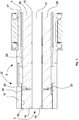
- FIG. 1 With reference to Figure 1 , there is shown a partial section of a boring machine tool 1 according to the invention that is suitable for boring or milling workpieces, provided with a machining axis Z shown by a dashed and dotted line.
- the boring machine tool 1 comprises a boring rod or bar 2 provided with a first free end 3 to which in use a working tool is fixed, and a second end 4 opposite the first end 3 that is rotatably connected to an axial movement slide of the boring machine tool 1, of known type and not illustrated in the drawings.
- the boring bar 2 can comprise an external shaft 26 in the shape of a tubular sleeve comprising a cylindrical opening arranged for housing an internal shaft 72 of the boring bar 2.
- the external shaft 26 and the internal shaft 72 are mounted in such a manner that an inner face 30 of the external shaft 26 and an outer face 16 of the internal shaft 72 are separated by a tubular passage 15 arranged, in use, for receiving a fluid, for example oil, at a supply pressure Pa.
- the boring machine tool 1 further comprises a hydrostatic supporting apparatus 5 suitable for supporting slidably and rotatably the boring bar 2.
- the boring bar 2 is movable rotatably around and in translation along the machining axis Z.
- the hydrostatic supporting apparatus 5 comprises spindle means 6 rotatably fixed by connecting means, not illustrated, to the boring machine tool 1.
- the spindle means 6 comprises a spindle 27, in the shape of a hollow tubular sleeve comprising a cylindrical cavity arranged for housing the boring bar 2.
- the spindle 27 is connected to a seat of the connecting means by rolling bearings 8 that permit the rotation thereof around the machining axis Z and simultaneously prevent the linear movement thereof along said machining axis Z.
- the spindle 27 is rotated around the machining axis Z by actuating means of the machine tool 1 that is of known type and is not illustrated in the figures.
- Antirotation means comprising for example one or more tabs fixed to the spindle 27 and slidably engaged in respective longitudinal grooves of the external shaft 26, prevents the corresponding rotation between the spindle 27 and the boring bar 2 and transmits the rotation motion to the latter.
- the hydrostatic supporting apparatus 5 further comprises hydrostatic supporting means 9 arranged for supporting the boring bar 2 hydrostatically by means of the fluid at a working pressure Pw.
- the cylindrical cavity of the spindle 27 is provided with an internal wall 10 on which is mounted by interference the hydrostatic supporting means 9 that is provided with an external surface 23, which abuts, in particular, sealingly, on the internal wall 10.
- the boring bar 2 and the spindle 27 are separated by an interspace 25.
- the pressurised fluid is delivered that has to supply the hydrostatic supporting means 9 and coming from the tubular passage 15 with which the interspace 25 is flowingly connected.
- the interspace 25 is interposed between the internal wall 10 of the spindle 27, or an internal surface 37 of the hydrostatic supporting means 9, and an external wall 29 of the external shaft 26 and extends substantially over the entire length of the spindle means 6.
- the hydrostatic supporting apparatus 5 further comprises a supply system 12, shown in Figures 2 and 3 and connected to fluid delivering means, not illustrated, for example a hydraulic pump, to supply the fluid at the supply pressure Pa to the hydrostatic supporting means 9 via the tubular passage 15 obtained inside the boring bar 2 and through the interspace 25.
- fluid delivering means not illustrated, for example a hydraulic pump
- the supply system 12 comprises manifold means 24 mounted on the boring bar 2, for example near the second end 4 thereof.
- the manifold means 24 comprises one or more inlet conduits 13 that place the fluid delivering means in flowing communication with the tubular passage 15 through a respective inlet hole 18.
- Each inlet conduit 13 can be substantially perpendicular to the machining axis Z and can be made of a through hole obtained in the thickness of the manifold means 24 and in the thickness of the external shaft 26. Each inlet conduit 13 leads into the tubular passage 15 via the respective inlet hole 18.
- the pressurised fluid is then supplied by the supply system 12 to the tubular passage 15 obtained between the internal shaft 72 and the external shaft 26 of the boring bar 2 through the inlet hole 18.
- the supply system 12 further comprises one or more passage conduits 33 that connect the tubular passage 15 to the interspace 25 via respective passage holes 32, thus enabling the fluid to pass at the supply pressure Pa to the hydrostatic supporting means 9, which is in turn flowingly connected to the interspace 25.
- the passage conduits 33 can be arranged substantially perpendicularly to the machining axis Z and can be arranged between the first end 3 and the second end 4.
- Each passage conduit 33 can be made in the form of a through hole obtained in the thickness of the external shaft 26.
- the fluid at the supply pressure Pa transits from the delivery means to the hydrostatic supporting means 9, passing successively through the inlet conduits 13, the tubular passage 15, the passage conduits 33 and the interspace 25, as indicated by the arrows of Figures 2 and 3 and as explained better below to supply the hydrostatic supporting means 9.
- the manifold means 24 has a reduced diameter compared with the manifold means of prior-art boring machine tools in which the pressurised fluid is supplied through the spindle means 6. In this manner, having a smaller diameter, at the same rotation speed there are lower peripheral speeds and it is thus possible to dimension the passages of the fluid and the clearance between the movable and fixed parts of the manifold means 24 so as to reduce the leaks of fluid and contain the generation of heat through friction.
- the smaller dispersions of fluid enable fluid delivering means to be obtained for delivering fluid to the supply system 12 (comprising for example a hydraulic pump and a tank that are not illustrated) that are smaller and more compact than those of prior art boring machine tools.
- the hydrostatic supporting means 9 is provided with a plurality of hydrostatic supporting pockets 11 shown, in particular, in Figures 4 to 10 and 12 to 14 and supplied by the fluid at the working pressure Pw via hydraulic resistance supply means 64 for supporting the boring bar 2 along the machining axis Z.
- the plurality of hydrostatic supporting pockets 11, suitably supplied by the pressurised fluid, creates a film of fluid having a required thickness that is able to support the boring bar 2 suitably and stiffly, preventing undesired and harmful contacts between the internal surface 37 and the external wall 29 of the external shaft 26 of the boring bar 2.
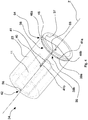
- Each hydrostatic supporting pocket 11 is made on the internal surface 37 of the spindle means 6 and is delineated with a dashed line in Figure 4 and Figure 9 . For the sake of clarity, in Figure 4 only one hydrostatic supporting pocket 11 is shown.
- the hydrostatic supporting pockets 11 can be spaced angularly apart on the internal surface 37 and/or longitudinally spaced along a direction that is substantially parallel to the machining axis Z.
- manifold means 24 of the boring machine tool 1 supplies all the hydrostatic supporting pockets 11 of the hydrostatic supporting apparatus 5 and dedicated manifold means is not necessary for each hydrostatic supporting pocket 11.
- the hydrostatic supporting means 9 further comprises annular groove means 45 obtained on the internal surface 37, the annular groove means 45 being reached by the pressurised fluid coming from the interspace 25 at the supply pressure Pa.
- the annular groove means 45 is flowingly connected with the interspace 25.
- the pressurised fluid passes from the interspace 25 to the annular groove means 45, at which the fluid leads at the supply pressure Pa.
- the hydraulic supply resistance means 64 is arranged for varying the pressure of the fluid, in particular, hydraulic supply resistance means 64 is arranged for taking the fluid pressure from the supply pressure Pa, for example of 20 bar, to a set working pressure Pw, for example of 10 bar, where, in particular, the supply pressure Pa has a greater value than the working pressure Pw.
- the hydraulic supply resistance means 64 creates an input hydraulic resistance to the passage of the pressurised fluid thereupon.
- the hydraulic supply resistance means 64 comprises pocket supply means 46, 49 made on the internal surface 37 and flowingly connected with the plurality of hydrostatic supporting pockets 11 by pocket supply conduit means 38 of the hydraulic supply resistance means 64 to supply each hydrostatic supporting pocket 11 with the fluid at working pressure Pw.
- the hydraulic supply resistance means 64 further comprises a passage zone 59 defined by a portion of the internal surface 37 of the hydrostatic supporting means 9 and by the external wall 29 of the external shaft 26 and is supplied by the fluid at the supply pressure Pa by means of the annular groove means 45.
- the passage zone 59 is arranged between the annular groove means 45 and the pocket supply means 46, 49.
- the pocket supply means 46, 49 is supplied with the fluid through the passage zone 59, which acts as an inlet, i.e. supply, hydraulic resistance of the hydrostatic supporting means 9 such as to vary the pressure of the fluid from the supply pressure Pa to the working pressure Pw.
- the passage zone 59 has, further, a height that is variable according to a radial position of the boring bar 2 and according to a work load applied thereto.
- a variation of the radial position of the boring bar 2 entails a variation of the thickness of the film of fluid in the passage zone 59, so the inlet hydraulic resistance varies consequently that depends on the thickness of the passage zone 59.
- the variation in the thickness of the film of pressurised fluid is obtained along the machining axis Z, i.e. along the longitudinal extent of the internal surface 37 of the hydrostatic supporting means 9, but also circumferally, i.e. along the angular extent of the internal surface 37 of the hydrostatic supporting means 9.
- the pocket supply conduit means 38 is interposed between the pocket supply means 46, 49 and the hydrostatic supporting pockets 11.
- the pocket supply conduit means 38 comprises one or more supply conduits 39 made on the external surface 23 of the hydrostatic supporting means 9.
- Each supply conduit 39 comprises, in particular, a groove 41 made for mechanical processing on the external surface 23 of the hydrostatic supporting means 9 and closed, in particular sealingly, above, by the internal wall 10 of the spindle 27.
- the supply conduits 39 lead into a respective hydrostatic supporting pocket 11 via a discharge hole 40.
- the supply conduits 39 thus connect a hydrostatic supporting pocket 11 to the pocket supply means 46, 49 supplied by the fluid at the working pressure Pw.
- the hydrostatic supporting means 9 further comprises discharging means 42 arranged for collecting the fluid at the working pressure Pw that exits the hydrostatic supporting pocket 11 and conveying the fluid outside the spindle means 6 via outlet channels 43 of the discharging means 42.
- the discharging means 42 comprises a plurality of through openings 56, shown in particular in Figures 5 and 10 , in particular arranged aligned in groups.
- each group of through openings 56 is interposed between adjacent hydrostatic supporting pockets 11.
- the through openings 56 of the same group are joined by longitudinal discharge grooves 44 of the discharging means 42 made on the external surface 23 and connected to annular discharge grooves 57 flowingly connected with the outlet channels 43.
- a further passage zone 67 comprising a transverse zone interposed between the hydrostatic supporting pockets 11 and the through openings 56, is defined by a portion of the internal surface 37 of the hydrostatic supporting means 9 and by the external wall 29 of the external shaft 26, and is supplied by the fluid at the working pressure Pw that exits the hydrostatic supporting pockets 11.
- the pressurised fluid exits the hydrostatic supporting pockets 11 spreading on the internal surface 37 and then flows into the through openings 56.
- the through openings 56 are then supplied with the fluid through the further passage zone 67, which acts as an outlet, i.e. discharge, hydraulic resistance of the hydrostatic supporting means 9 that is such as to vary the pressure of the fluid from the working pressure Pw to an outlet pressure Pout.
- the outlet pressure Pout is generally 0 bar.
- the further passage zone 67 has a height that varies according to a radial position of the boring bar 2 according to a work load applied thereto just like the passage zone 59.
- a variation of the radial position of the boring bar 2 entails a variation in the thickness of the film of fluid in the further passage zone 67, so that the outlet hydraulic resistance varies accordingly, which depends on the thickness of the film of fluid in the further passage zone 67.
- the working pressure Pw of the fluid varies.
- the longitudinal discharge grooves 44 and the radial discharge grooves 57 are made on the external surface 23 and are closed, in particular sealingly, above by the internal wall 10 of the spindle means 6.
- the hydrostatic supporting means 9 comprises first hydrostatic supporting means 34, which can be arranged near the second end 4 of the boring bar 2 and shown, in particular, in Figures 4 to 8 , and second hydrostatic supporting means 35, which can be arranged further from said second end 4 with respect to the first hydrostatic supporting means 34 and shown, in particular, in Figures 9 to 14 .
- the second hydrostatic supporting means 35 is thus interposed between the first end 3 and the first hydrostatic supporting means 34.
- Figures 4 and 9 are simplified partial perspective views respectively of the first hydrostatic supporting means 34 and of the second hydrostatic supporting means 35 in configurations dismantled from the boring machine tool 1 to enable the components thereof to be identified more clearly.
- the second hydrostatic supporting means 35 can be arranged near the second end 4 of the boring bar 2 and the first hydrostatic supporting means 34 can be arranged further from said second end 4 with respect to the second hydrostatic supporting means 35.
- the first hydrostatic supporting means 34 and the second hydrostatic supporting means 35 can be arranged on opposite sides with respect to the passage conduits 33.
- the first hydrostatic supporting means 34 and the second hydrostatic supporting means 35 can each be made in the shape of a brass.
- the internal surface 37 of the hydrostatic supporting means 9 is the internal surface 37 of each brass and has a substantially cylindrical shape.
- the external surface 23 of the hydrostatic supporting means 9 is the external surface 23 of each brass and also has a substantially cylindrical shape.
- the first hydrostatic supporting means 34 comprises a plurality of hydrostatic supporting pockets 11 spaced angularly apart on the internal surface 37 around the axis Z.
- the pocket supply means of the first hydrostatic supporting means 34 comprises a plurality of supply slots 46, in particular, at least one pair of supply slots 46a, 46b arranged offset, in particular, spaced angularly apart by a displacement angle ⁇ , for example equal to 180°, to supply the same hydrostatic supporting pocket 11.
- Each supply slot of the pair of supply slots 46a, 46b is arranged on opposite sides with respect to the hydrostatic supporting pocket 11, which supplies, in particular, at an angular distance equal to substantially half the displacement angle ⁇ , i.e. in the case of a displacement angle ⁇ equal to 180°, equal to 90°.
- hydrostatic supporting pockets 11 are arranged spaced angularly apart on the internal surface 37 and each hydrostatic supporting pocket 11 is supplied by a respective pair of supply slots 46a, 46b.
- the supply slots 46 of the first hydrostatic supporting means 34 can be spaced angularly apart on the internal surface 37.
- the supply conduits 39 of the first hydrostatic supporting means 34 comprises a semicircular supply conduit 39a provided with a semicircular groove 41a that extends circumferally over the external surface 23 and a longitudinal supply conduit 39b provided with a longitudinal groove 41b that extends on the external surface 23 along a direction substantially parallel to the machining axis Z and is substantially perpendicular to the semicircular supply conduit 39a.
- the longitudinal supply conduit 39b is connected to the semicircular supply conduit 39a substantially at a median zone of the semicircular supply conduit 39a via a connecting hole 66.
- the pressurised fluid is supplied to the semicircular supply conduit 39a from the pair of supply slots 46a, 46b that are offset by the displacement angle ⁇ .
- the longitudinal supply conduit 39b leads into the hydrostatic supporting pocket 11 via the discharge hole 40.
- the hydrostatic supporting pocket 11 is supplied by the fluid at the working pressure Pw via a pair of supply slots 46a, 46b offset by the displacement angle ⁇ .
- the supply slots 46a, 46b of a pair of supply slots are offset by about 90° with respect to the hydrostatic supporting pocket 11 which supply with pressurised fluid.
- An angular distance of about 90° of each supply slot 46a, 46b of a pair of supply slots with respect to the position of the hydrostatic supporting pocket 11 which supply makes the inlet hydraulic resistance almost independent of the film of fluid that is created between the hydrostatic supporting means 9 and the boring bar 2.
- the passage zone 59 comprises a circumferal zone of substantially annular shape interposed between the annular groove means 45 and the supply slots 46.
- the annular groove means 45 can comprise a pair of annular grooves 45a, 45b, arranged on opposite sides with respect to the supply slots 46.
- the inlet hydraulic resistance of the first hydrostatic supporting means 34 is achieved by the passage of the fluid at the supply pressure Pa on the passage zone 59 to reach the semicircular supply conduit 39a. As disclosed previously, the inlet hydraulic resistance of the first hydrostatic supporting means 34 is determined by the passage of the fluid from the annular groove means 45 to the passage zone 59. The fluid thus reaches the hydrostatic supporting pocket 11 at the working pressure Pw that is different from the supply pressure Pa.
- the value of the inlet hydraulic resistance of the first hydrostatic supporting means 34 is given by the combination of the two inlet hydraulic resistances that occur at the passage of the fluid respectively through each supply slot 46a, 46b of the pair of offset supply slots 46 which supply a single hydrostatic supporting pocket 11.
- Such hydraulic inlet resistances depend on the thickness of the film of pressurised fluid that is created at different portions of the passage zone 59 and is variable according to the work load applied to the boring bar 2. Nevertheless, as explained previously, the effect of the work load on the boring bar 2 is different along the extent of the passage zone 59, which entails a different thickness of the pressurised fluid at the circumference thereof.
- each inlet hydraulic resistance varies according to the distance of the portions of passage zones 59 from the application area A and according to the positions thereof with respect to the machining axis Z.
- the film of fluid that is created at a portion of passage zone 59 which supplies a first supply slot 46a positioned above the machining axis Z will have less thickness than the film of pressurised fluid that is created at a further portion of passage zone 59 which supplies a second supply slot 46b positioned below the machining axis Z i.e. spaced apart angularly by the displacement angle ⁇ , in particular by 180°, when a work load as in Figure 15 is applied to the boring bar 2.
- the inlet hydraulic resistance of the first hydrostatic supporting means 34 has a value that is almost independent of the film of fluid as each hydrostatic supporting pocket 11 of the first hydrostatic supporting means 34 is supplied by a pair of supply slots 46 offset by the displacement angle ⁇ .
- the second hydrostatic supporting means 35 comprises a plurality of hydrostatic supporting pockets 11 spaced angularly apart on the internal surface 37, in particular, at least three hydrostatic supporting pockets 11.
- an embodiment of the second hydrostatic supporting means 35 is shown in which the hydrostatic supporting pockets 11 are arranged in reciprocally aligned pairs along a direction substantially parallel to the machining axis Z.
- Figure 9 there is shown, for the sake of clarity, only one pair of the hydrostatic supporting pockets 11a, 11b that are longitudinally aligned reciprocally.
- the supply conduits 39 of the second hydrostatic supporting means 35 comprise a first longitudinal supply conduit 39c provided with a first longitudinal groove 41c obtained on the external surface 23 and which extends along a direction substantially parallel to the machining axis Z and a second longitudinal supply conduit 39d provided with a second longitudinal groove 41d obtained on the external surface 23 and which extends along a direction substantially parallel to the machining axis Z.
- the first longitudinal supply conduit 39c and the second longitudinal supply conduit 39d each supply a respective hydrostatic supporting pocket 11 of the pair of hydrostatic supporting pockets 11a, 11b of the second hydrostatic supporting means 35.
- the first longitudinal supply conduit 39c leads into a first hydrostatic supporting pocket 11a via a first discharge hole 40a
- the second longitudinal supply conduit 39d leads into a second hydrostatic supporting pocket 11b via a second discharge hole 40b, said second hydrostatic supporting pocket 11b being aligned along a direction substantially parallel to the machining axis Z with the first hydrostatic supporting pocket 11a.
- each hydrostatic supporting pocket 11 is arranged in the same angular sector of the respective supply conduits 39 that supply the hydrostatic supporting pocket 11 in such a manner that, following flexure and/or bending of the boring bar 2, an increase in the height of the passage zone 59 is matched by a decrease in the height of the corresponding further passage zone 67 and vice versa.
- the pocket supply means of the second hydrostatic supporting means 35 comprises one or more lesser through channels 49, in particular, a pair of lesser through channels 49a, 49b each obtained in the thickness of the second hydrostatic supporting means 35.
- Each lesser through channel 49 can have a longitudinal extent, i.e. be substantially parallel to the machining axis Z.
- the lesser through channels 49 are reciprocally parallel and spaced angularly apart on the internal surface 37.
- Each lesser through channel 49 is flowingly connected, at a respective end zone 51 thereof, to a respective supply conduit 39.
- a further end zone 53 of each lesser through channel 49, opposite the end zone 51 is blind.
- the pocket supply means of the second hydrostatic supporting means 35 further comprises one or more greater through channels 47, each obtained in the thickness of the second hydrostatic supporting means 35 and connected at a respective end part 48 to the interspace 25 from which the fluid comes at the supply pressure Pa through the annular groove 45.
- Each greater through channel 47 can have a longitudinal extent, i.e. be substantially parallel to the machining axis Z.
- Each lesser through channel 49 is placed next to each greater through channel 47.
- each lesser through channel 49 is interposed between each greater through channel 47. In this manner each lesser through channel 49 receives a quantity of pressurised fluid coming from the two respective greater through channels 47 adjacent thereto.
- the pressurised fluid in use passes from the greater through channels 47 to the lesser through channels 49 through the passage zone 59.
- the passage zone 59 thus comprises a transverse zone interposed between a greater through channel 47 and the lesser adjacent through channel 49.
- the inlet hydraulic resistance is achieved, in particular, by the passage of the fluid at the supply pressure Pa on the passage zone 59 to reach via the passage zone 59 the lesser through channels 49.
- the inlet hydraulic resistance of the second hydrostatic supporting means 35 is determined by the passage of the fluid from the greater through channels 47, where the fluid has a pressure equal to the supply pressure Pa, to the lesser through channels 49 passing on the passage zone 59.
- the value of the inlet hydraulic resistance of the second hydrostatic supporting means 35 is given by the combination of the two inlet hydraulic resistances that occur at the passage of the fluid respectively through each lesser through channel 47, which supplies a single hydrostatic supporting pocket 11.
- These inlet hydraulic resistances depend on the thickness of the film of pressurised fluid that is created at different portions of the passage zone 59 and is variable according to the work load applied to the boring bar 2. Nevertheless, again, the effect of the work load on the boring bar 2 is different along the extent of the passage zone 59, which entails a different thickness of the pressurised fluid at the passage zone 59 circumferally.
- each hydrostatic product 11 is supplied by only one respective supply conduit 39 arranged with the corresponding through channels 47, 49 and the relative passage zone 59 substantially aligned thereupon in a longitudinal direction and thus in the same angular sector. Consequently, each hydrostatic supporting pocket 11 is supplied via a hydraulic resistance substantially aligned thereupon and varies according to the thickness of the film of fluid that traverses a portion of the passage zone 59.
- the supply conduits 39 with the corresponding through channels 47, 49 and the relative passage zone 59, can be arranged in a different angular sector with respect to the hydrostatic supporting pockets 11 which supply.
- a suitable tool is mounted at the first end 3 of the boring bar 2.
- the boring bar 2 is moved along the machining axis Z and rotated around the machining axis Z, supported hydrostatically by the hydrostatic supporting apparatus 5.
- a fluid coming from the delivery means is conveyed at a set supply pressure Pa to the supply system 12 of the boring machine tool 1 to supply the hydrostatic supporting means 9 via the manifold means 24.
- the path that the fluid travels at the supply pressure Pa to reach the first hydrostatic supporting means 34 and the second hydrostatic supporting means 35 starts from the delivery means from which it comes and from the latter, through the manifold means 24, the fluid is conveyed to the inlet conduits 13, and the fluid then leads into the tubular passage 15 via the inlet hole 18.
- the fluid fills the tubular passage 15 being distributed between the outer face 16 of the internal shaft 72 and the internal face 30 of the external shaft 26.
- the fluid at the supply pressure Pa reaches, further, the interspace 25, filling the interspace 25 and being thus distributed between the outer face 29 of the external shaft 26 and the internal wall 10 of the spindle 27.
- the interspace 25 is flowingly connected to the hydrostatic supporting means 9, thus the pressurised fluid can reach the first hydrostatic supporting means 34 and the second hydrostatic supporting means 35 through the interspace 25.
- the pressurised fluid reaches the annular groove 45 of the first hydrostatic supporting means 34 and leads onto the passage zone 59, creating the inlet hydraulic resistance of the first hydrostatic supporting means 34. Thereafter, the fluid goes past the pocket supply means and, in particular, the supply slots 46 of the first hydrostatic supporting means 34 and reaches the external surface 23 leading into the supply conduits 39 obtained thereupon.
- the hydrostatic supporting pockets 11 of the first hydrostatic supporting means 34 are then supplied by the pressurised fluid through the supply conduits 39 (as indicated by the arrows in Figure 6 ) that in fact create a film of fluid having a requested thickness that is able to support the boring bar 2 suitably and stiffly.
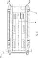
- the first hydrostatic supporting means 34 is shown, provided with a plurality of hydrostatic supporting pockets 11.
- a section is shown of the first hydrostatic supporting means 34 taken along a plane that is perpendicular to the machining axis Z that highlights the presence of two hydrostatic supporting pockets 11. Another two will be present on the opposite section of the first hydrostatic supporting means 34 not shown in Figure 6 .
- Each of the hydrostatic supporting pockets 11 is supplied, as disclosed previously, by a pair of supply conduits 39 that each receive the pressurised fluid from a respective supply slot 46, the two supply slots 46 being angularly displaced by the displacement angle ⁇ .
- the second hydrostatic supporting means 35 is supplied.
- the pressurised fluid reaches the greater through channels 47 of the second hydrostatic supporting means 35 and leads onto the passage zone 59. Thereafter, the fluid traverses the passage zone 59, creating the inlet hydraulic resistance of the second hydrostatic supporting means 35 and leads into the lesser through channels 49. Owing to the latter, the fluid reaches outside the second hydrostatic supporting means 35, where it leads into the supply conduits 39 made on the external surface 23.
- the hydrostatic supporting pockets 11 of the second hydrostatic supporting means 35 are then supplied by the pressurised fluid via the supply conduits 39 (as indicated by the arrows in Figure 12 ) which create also in this case a film of fluid having a required thickness that is able to support the boring bar 2 suitably and stiffly.
- the second hydrostatic supporting means 35 is shown that is provided with a plurality of pairs of the hydrostatic supporting pockets 11.
- a section of the second hydrostatic supporting means 35 taken along a plane that is perpendicular to the machining axis Z that highlights the presence of two pairs of hydrostatic supporting pockets 11. Another two will be present on the opposite section of the second hydrostatic supporting means 35 not shown in Figure 12 .
- Each pair of the hydrostatic supporting pockets 11 is supplied, as disclosed previously, by a lesser through channel 49.
- the radial discharge grooves 57 lastly convey the fluid to the outlet channels 43, which lead outside the spindle 27 (as indicated by the arrows in Figures 8 and 14 ).
- the film of fluid that is formed between the internal surface 37 of the hydrostatic support means 9 and the external wall 29 of the boring bar 2 during the operation prevents direct contact between the hydrostatic support means 9 and the boring bar 2 and thus enables the risk of damage through friction and wear to the aforesaid surface and to the aforesaid wall to be decreased.
- the boring machine tool 1 Owing to the inlet and outlet hydraulic resistances of the hydrostatic support means 9 that vary according to movements and deformation that depend on the load applied to the boring bar 2 and to the forces that entail flexure and/or bending thereupon, the boring machine tool 1 that is the object of the present invention has greater stiffness in operation, which ensures better efficiency and efficacy during operation, in particular in the case of load imbalances that occur on the boring bar 2 with respect to boring machines of known type.
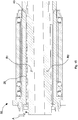
- FIG 15 which shows a partial section of the second hydrostatic supporting means 35 when the boring bar 2 flexes, for example downwards, because of being subjected to a load at the first end 3 thereof, it is observed that the height of the passage zone 59, i.e. the thickness of the film of pressurised fluid at the hydraulic supply resistance means 64 positioned above the machining axis Z decreases and, consequently, the upper inlet hydraulic resistance increases.
- the height of the further passage zone 67 i.e.
- the thickness of the film of pressurised fluid at the internal surface 37 from which the pressurised fluid passes that exits by a pair of hydrostatic supporting pockets 11 that are positioned above the machining axis Z increases and, consequently, the upper outlet hydraulic resistance decreases.
- the working pressure Pw decreases in the hydrostatic supporting pockets 11 positioned above the machining axis Z, this causing a decrease in the force of reaction R1.
- This decrease in pressure and thus of the force of reaction R1 is greater than what is obtained in the prior-art boring machine tools in which the inlet resistance is fixed.
- the inlet hydraulic resistance can be made independent of the gap of the pressurised fluid supplying a hydrostatic supporting pocket 11 with supply slots 46 that are phase displaced angularly, for example by an angle of 180°, and are arranged offset by about half the displacement angle ⁇ with respect to the hydrostatic supporting pocket 11 which supply, for example at an angular distance of 90°.
- the resultant of the two reaction forces R1 and R2 balances the force that caused the flexure and/or bending of the boring bar 2 more stiffly compared with known boring machine tools.
- the hydrostatic supporting apparatus 5 applied to the boring machine tool 1 thus enables the boring bar 2 to be supported precisely and stiffly both during rotation and translation, and the load imbalances applied to the boring bar 2 to be counterbalanced effectively.
- the boring machine tool 1 enables a single inlet manifold to be used to supply the pressurised fluid and does not require dedicated manifolds to be provided for each hydrostatic supporting pocket, or groups of hydrostatic supporting pockets that a resistance supplies as in prior-art boring machine tools in which the inlet pressure is fixed. This makes the supply circuit simpler than in prior-art supply circuits and entails small losses of supply fluid.
- the supply pressure of the hydrostatic pockets does not depend on the machining tolerances of the boring bar 2 and of the hydrostatic supporting means 9.
Landscapes
- Engineering & Computer Science (AREA)
- Mechanical Engineering (AREA)
- Drilling And Boring (AREA)
- Earth Drilling (AREA)
- Cutting Tools, Boring Holders, And Turrets (AREA)
Claims (15)
- Bohrmaschinenwerkzeug (1), das zum Durchführen einer Bohraufgabe an einem Werkstück angeordnet ist und mit einer Bearbeitungsachse (Z) versehen ist, wobei das Bohrmaschinenwerkzeug (1) umfasst:- eine Bohrstange (2), die zum Abstützen eines Arbeitswerkzeugs an einem ersten Ende (3) davon angeordnet ist;- eine hydrostatische Stützvorrichtung (5), die zum verschiebbaren und drehbaren Abstützen der Bohrstange (2) angeordnet ist, mit einer Spindeleinrichtung (6), die an einer Verbindungseinrichtung des Bohrmaschinenwerkzeugs (1) drehbar befestigt ist, und eine hydrostatische Stützeinrichtung (9), die innerhalb der Spindeleinrichtung (6) montiert ist und eine innere Oberfläche (37) umfasst, die mit einer Vielzahl von hydrostatischen Stützfächern (11; 11 a, 11 b) versehen ist, die einer Außenwand (29) der Bohrstange (2) zugewandt sind, um die letztere abzustützen, wobei jedem hydrostatischen Stützfach (11; 11 a, 11 b) der Vielzahl von hydrostatischen Stützfächern (11; 11 a, 11 b) ein Fluid mit einem Arbeitsdruck (Pw) zugeführt wird;- ein Zufuhrsystem (12), das zum Zuführen des Fluids mit einem Zufuhrdruck (Pa) zur hydrostatischen Stützeinrichtung (9) angeordnet ist;wobei das Bohrmaschinenwerkzeug (1) dadurch gekennzeichnet ist, dass das Zufuhrsystem (12) eine Rohrverteilereinrichtung (24) umfasst, die an der Bohrstange (2) montiert ist und zum Befördern des Fluids zur hydrostatischen Stützeinrichtung (9) über einen röhrenförmigen Durchlass (15) angeordnet ist, der innerhalb der Bohrstange (2) erhalten ist.
- Bohrmaschinenwerkzeug (1) nach Anspruch 1, wobei die Bohrstange (2) eine äußere Welle (26) mit einer zylindrischen Öffnung umfasst, die zum Aufnehmen einer inneren Welle (72) der Bohrstange (2) angeordnet ist, wobei die äußere Welle (26) und die innere Welle (72) in einer solchen Weise montiert sind, dass eine innere Fläche (30) der äußeren Welle (26) und eine äußere Fläche (16) der inneren Welle (72) durch den röhrenförmigen Durchlass (15) getrennt sind.
- Bohrmaschinenwerkzeug (1) nach Anspruch 2, wobei die Rohrverteilereinrichtung (24) eine oder mehrere Einlassleitungen (13), die in Form von Durchgangslöchern hergestellt sind, die in der Dicke der Rohrverteilereinrichtung (24) und der äußeren Welle (26) erhalten sind, zum Zuführen des Fluids zum röhrenförmigen Durchlass (15) umfasst.
- Bohrmaschinenwerkzeug (1) nach Anspruch 2 oder 3, wobei das Zufuhrsystem (12) ferner eine oder mehrere Durchlassleitungen (33) umfasst, die zum Verbinden des röhrenförmigen Durchlasses (15) mit der hydrostatischen Stützeinrichtung (9) durch jeweilige Durchlasslöcher (32) angeordnet sind und in Form von Durchgangslöchern hergestellt sind, die in der Dicke der äußeren Welle (26) erhalten sind.
- Bohrmaschinenwerkzeug (1) nach einem vorangehenden Anspruch, wobei die Rohrverteilereinrichtung (24) an der Bohrstange (2) an einem zweiten Ende (4) davon entgegengesetzt zum ersten Ende (3) montiert ist.
- Bohrmaschinenwerkzeug (1) nach einem vorangehenden Anspruch, wobei der Vielzahl von hydrostatischen Stützfächern (11; 11a, 11 b) das Fluid mit dem Arbeitsdruck (Pw) über eine hydraulische Zufuhrwiderstandseinrichtung (64) zugeführt wird, die einen hydraulischen Einlasswiderstand für den Durchlass des Fluids erreicht und eine Fachzufuhreinrichtung (46, 49) umfasst, die an der inneren Oberfläche (37) hergestellt ist, mit jedem hydrostatischen Stützfach (11; 11 a, 11 b) strömend verbunden ist und der das Fluid durch eine Durchlasszone (59) zugeführt wird, die durch einen Teil der inneren Oberfläche (37) und durch die Außenwand (29) der Bohrstange (2) definiert ist, wobei die Durchlasszone (59) eine Höhe aufweist, die gemäß einer radialen Position der Bohrstange (2) variiert, um eine Veränderung des hydraulischen Einlasswiderstandes der hydraulischen Zufuhrwiderstandseinrichtung (64) zu bestimmen.
- Bohrmaschinenwerkzeug (1) nach Anspruch 6, wobei die Durchlasszone (59) zwischen die Fachzufuhreinrichtung (46, 49) und eine ringförmige Nut (45) eingefügt ist, die strömend mit dem Zufuhrsystem (12) des Zufuhrdrucks (Pa) verbunden ist.
- Bohrmaschinenwerkzeug (1) nach Anspruch 6 oder 7, wobei die hydraulische Zufuhrwiderstandseinrichtung (64) eine Fachzufuhrleitungseinrichtung (38) umfasst, die die Fachzufuhreinrichtung (46, 49) mit der Vielzahl von hydrostatischen Stützfächern (11; 11a, 11 b) verbindet.
- Bohrmaschinenwerkzeug (1) nach Anspruch 8, wobei die Fachzufuhrleitungseinrichtung (38) eine Zufuhrleitung (39) mit einer Nut (41) umfasst, die an einer äußeren Oberfläche (23) der hydrostatischen Stützeinrichtung (9) hergestellt ist und oben durch eine Innenwand (10) der Spindeleinrichtung (6) geschlossen ist, wobei die Zufuhrleitung (39) zu einem jeweiligen hydrostatischen Stützfach (11) über ein Auslassloch (40) führt.
- Bohrmaschinenwerkzeug (1) nach Anspruch 9, wobei jedes hydrostatische Stützfach (11; 11 a, 11 b) nach außen an eine Auslasseinrichtung (42) durch eine weitere Durchlasszone (67), die zwischen jedes hydrostatische Stützfach (11; 11 a, 11 b) eingefügt ist, und durch Öffnungen (56), die zum Befördern des Fluids außerhalb die Spindeleinrichtung (6) angeordnet sind, auslässt, wobei der weiteren Durchlasszone (67) das Fluid mit dem Arbeitsdruck (Pw) zugeführt wird und sie eine Höhe aufweist, die gemäß der radialen Position der Bohrstange (2) variiert.
- Bohrmaschinenwerkzeug (1) nach einem der Ansprüche 8 bis 10, wobei die hydrostatische Stützeinrichtung (9) eine erste hydrostatische Stützeinrichtung (34) umfasst, wobei die Fachzufuhreinrichtung mindestens ein Paar von Zufuhrschlitzen (46a, 46b) zum Zuführen des Druckfluids zur Fachzufuhrleitungseinrichtung (38) umfasst, wobei die Zufuhrschlitze (46a, 46b) des Paars von Zufuhrschlitzen im Winkel um einen Verschiebungswinkel (α) auseinander beabstandet sind und um etwa 90°in Bezug auf ein hydrostatisches Stützfach (11), zu dem sie zuführen, verschoben sind.
- Bohrmaschinenwerkzeug (1) nach Anspruch 11, wobei die Fachzufuhrleitungseinrichtung (38) eine halbkreisförmige Zufuhrleitung (39a), die mit einer halbkreisförmigen Nut (41 a) versehen ist, die sich auf dem Umfang an der äußeren Oberfläche (23) erstreckt, und eine longitudinale Zufuhrleitung (39b), der mit einer longitudinalen Nut (41 b) versehen ist, die sich an der äußeren Oberfläche (23) entlang einer Richtung erstreckt, die zur halbkreisförmigen Zufuhrleitung (39a) im Wesentlichen senkrecht ist, umfasst, wobei das Druckfluid zur halbkreisförmigen Zufuhrleitung (39a) durch das Paar von Zufuhrschlitzen (46a, 46b) zugeführt wird.
- Bohrmaschinenwerkzeug (1) nach einem der Ansprüche 10 bis 12, wobei die hydrostatische Stützeinrichtung (9) eine zweite hydrostatische Stützeinrichtung (35) umfasst, wobei die Fachzufuhreinrichtung (46, 49) und die Fachzufuhrleitungseinrichtung (38) im gleichen Winkelsektor angeordnet sind, in dem ein jeweiliges hydrostatisches Stützfach (11; 11 a, 11 b), zu dem sie zuführen, angeordnet ist, in einer solche Weise, dass nach einem Übergang und/oder Biegen der Bohrstange (2) die Höhe der Durchlasszone (59) der hydraulischen Zufuhrwiderstandseinrichtung (64) zunimmt und die Höhe der weiteren Durchlasszone (67) der hydrostatischen Stützfächer (11; 11 a, 11 b) abnimmt und umgekehrt.
- Bohrmaschinenwerkzeug (1) nach Anspruch 13, wobei die Vielzahl von hydrostatischen Stützfächern (11; 11 a, 11 b) ein Paar von hydrostatischen Stützfächern (11a, 11 b) umfasst, die wechselseitig ausgerichtet entlang einer Richtung angeordnet sind, die zur Bearbeitungsachse (Z) des Bohrmaschinenwerkzeugs (1) im Wesentlichen parallel ist.
- Bohrmaschinenwerkzeug (1) nach Anspruch 13 oder 14, wobei die Fachzufuhreinrichtung eine Vielzahl von geringeren Durchgangskanälen (49), wobei jeder geringere Durchgangskanal (49) in der Dicke der zweiten hydraulischen Stützeinrichtung (35) erhalten ist und mit einer jeweiligen Zufuhrleitung (39) zum Zuführen des Arbeitsdrucks (Pw) zu einem jeweiligen hydrostatischen Stützfach (11; 11 a, 11 b) strömend verbunden ist, und eine Vielzahl von größeren Durchgangskanälen (47), umfasst, wobei jeder größere Durchgangskanal (47) in der Dicke der zweiten hydrostatischen Stützeinrichtung (35) erhalten ist und an einem Endteil (48) mit der ringförmigen Nut (45), um das Fluid mit dem Zufuhrdruck (Pa) zu empfangen, und mit jedem der geringeren Durchgangskanäle (49) über die Durchlasszone (59) zum Zuführen des Fluids mit dem Arbeitsdruck (Pw) zu der Vielzahl von geringeren Durchgangskanälen (49) strömend verbunden ist
Applications Claiming Priority (1)
| Application Number | Priority Date | Filing Date | Title |
|---|---|---|---|
| IT000283A ITMO20130283A1 (it) | 2013-10-09 | 2013-10-09 | Macchina utensile alesatrice |
Publications (3)
| Publication Number | Publication Date |
|---|---|
| EP2859974A2 EP2859974A2 (de) | 2015-04-15 |
| EP2859974A3 EP2859974A3 (de) | 2015-05-20 |
| EP2859974B1 true EP2859974B1 (de) | 2017-02-01 |
Family
ID=49683928
Family Applications (1)
| Application Number | Title | Priority Date | Filing Date |
|---|---|---|---|
| EP14187960.1A Active EP2859974B1 (de) | 2013-10-09 | 2014-10-07 | Werkzeug für eine Bohrmaschine |
Country Status (2)
| Country | Link |
|---|---|
| EP (1) | EP2859974B1 (de) |
| IT (1) | ITMO20130283A1 (de) |
Families Citing this family (2)
| Publication number | Priority date | Publication date | Assignee | Title |
|---|---|---|---|---|
| CN108453312B (zh) * | 2018-02-13 | 2019-10-22 | 肖亚晖 | 一种锁定式管状工件的内壁加工装置 |
| CN113210663B (zh) * | 2021-05-20 | 2022-07-19 | 中石化石油工程技术服务有限公司 | 镗孔装置、镗孔方法及艉轴安装方法 |
Family Cites Families (3)
| Publication number | Priority date | Publication date | Assignee | Title |
|---|---|---|---|---|
| US3899222A (en) * | 1971-06-02 | 1975-08-12 | Yakov Idelevich Mendelevsky | Hydrostatic bearing |
| US5540526A (en) * | 1994-09-06 | 1996-07-30 | Leblond Makino Machine Tool Company | Fluid bearing tool and a method for forming the same |
| ITMO20120003A1 (it) * | 2012-01-10 | 2013-07-11 | Pama Spa | Dispositivo di misurazione di coppia per macchina alesatrice |
-
2013
- 2013-10-09 IT IT000283A patent/ITMO20130283A1/it unknown
-
2014
- 2014-10-07 EP EP14187960.1A patent/EP2859974B1/de active Active
Non-Patent Citations (1)
| Title |
|---|
| None * |
Also Published As
| Publication number | Publication date |
|---|---|
| EP2859974A2 (de) | 2015-04-15 |
| EP2859974A3 (de) | 2015-05-20 |
| ITMO20130283A1 (it) | 2015-04-10 |
Similar Documents
| Publication | Publication Date | Title |
|---|---|---|
| KR100485838B1 (ko) | 고압및높은상대속도용로터리조인트 | |
| US3493273A (en) | Hydrostatic machine tool spindle | |
| US20180214999A1 (en) | Spindle unit for a machine tool for fine-machining workpieces that have grooved-shaped profiles | |
| WO2000014411A1 (en) | Vane type rotary machine | |
| US5540526A (en) | Fluid bearing tool and a method for forming the same | |
| EP2859974A2 (de) | Werkzeug für eine Bohrmaschine | |
| US3331469A (en) | Arrangements for lubricating nut and screw devices | |
| DK155230B (da) | Reversibel, roterende fluidummotor | |
| JP5658515B2 (ja) | 軸受装置、オイル分配の機構および方法 | |
| US3415138A (en) | Worm-rack transmission with hydrostatic tooth bearings | |
| JP7256556B6 (ja) | ベーンの摺動軸受及び枢動軸受を伴う、回転式摺動ベーン機械 | |
| JP5228939B2 (ja) | 潤滑装置 | |
| JP4835484B2 (ja) | 主軸装置 | |
| JP2005076858A (ja) | ロータリー分配弁及び潤滑装置 | |
| US5989001A (en) | Planetary rotation machine with hydrostatically mounted control part, and control part for this purpose | |
| JPS63176890A (ja) | 環状回転油圧ジョイント | |
| JP4294733B2 (ja) | 工作機械 | |
| JP4811657B2 (ja) | スピンドル装置 | |
| JP4845114B2 (ja) | スピンドル装置 | |
| JP3935857B2 (ja) | スピンドル装置 | |
| Sadashivappa et al. | On the efficiency of the axial piston motor considering piston form deviations | |
| US4549822A (en) | Apparatus to distribute a highly-pressurized fluid medium | |
| US11346222B2 (en) | Rotary sliding vane machine with hydrostatic slide bearings for the vanes | |
| JP2005054913A (ja) | ロータリー分配弁及び潤滑装置 | |
| JP6645048B2 (ja) | 静圧流体軸受、その製造方法及びそれを用いた工作機械 |
Legal Events
| Date | Code | Title | Description |
|---|---|---|---|
| PUAI | Public reference made under article 153(3) epc to a published international application that has entered the european phase |
Free format text: ORIGINAL CODE: 0009012 |
|
| 17P | Request for examination filed |
Effective date: 20141007 |
|
| AK | Designated contracting states |
Kind code of ref document: A2 Designated state(s): AL AT BE BG CH CY CZ DE DK EE ES FI FR GB GR HR HU IE IS IT LI LT LU LV MC MK MT NL NO PL PT RO RS SE SI SK SM TR |
|
| AX | Request for extension of the european patent |
Extension state: BA ME |
|
| PUAL | Search report despatched |
Free format text: ORIGINAL CODE: 0009013 |
|
| AK | Designated contracting states |
Kind code of ref document: A3 Designated state(s): AL AT BE BG CH CY CZ DE DK EE ES FI FR GB GR HR HU IE IS IT LI LT LU LV MC MK MT NL NO PL PT RO RS SE SI SK SM TR |
|
| AX | Request for extension of the european patent |
Extension state: BA ME |
|
| RIC1 | Information provided on ipc code assigned before grant |
Ipc: B23Q 11/12 20060101ALI20150415BHEP Ipc: B23B 29/02 20060101AFI20150415BHEP Ipc: B23Q 1/38 20060101ALI20150415BHEP Ipc: B23Q 5/32 20060101ALI20150415BHEP |
|
| R17P | Request for examination filed (corrected) |
Effective date: 20151120 |
|
| RBV | Designated contracting states (corrected) |
Designated state(s): AL AT BE BG CH CY CZ DE DK EE ES FI FR GB GR HR HU IE IS IT LI LT LU LV MC MK MT NL NO PL PT RO RS SE SI SK SM TR |
|
| GRAP | Despatch of communication of intention to grant a patent |
Free format text: ORIGINAL CODE: EPIDOSNIGR1 |
|
| INTG | Intention to grant announced |
Effective date: 20160429 |
|
| GRAJ | Information related to disapproval of communication of intention to grant by the applicant or resumption of examination proceedings by the epo deleted |
Free format text: ORIGINAL CODE: EPIDOSDIGR1 |
|
| GRAS | Grant fee paid |
Free format text: ORIGINAL CODE: EPIDOSNIGR3 |
|
| GRAP | Despatch of communication of intention to grant a patent |
Free format text: ORIGINAL CODE: EPIDOSNIGR1 |
|
| INTC | Intention to grant announced (deleted) | ||
| RIN1 | Information on inventor provided before grant (corrected) |
Inventor name: NAINER, ALBERTO Inventor name: PROCACCINI, MAURO |
|
| INTG | Intention to grant announced |
Effective date: 20160930 |
|
| GRAA | (expected) grant |
Free format text: ORIGINAL CODE: 0009210 |
|
| AK | Designated contracting states |
Kind code of ref document: B1 Designated state(s): AL AT BE BG CH CY CZ DE DK EE ES FI FR GB GR HR HU IE IS IT LI LT LU LV MC MK MT NL NO PL PT RO RS SE SI SK SM TR |
|
| REG | Reference to a national code |
Ref country code: GB Ref legal event code: FG4D |
|
| REG | Reference to a national code |
Ref country code: CH Ref legal event code: EP Ref country code: AT Ref legal event code: REF Ref document number: 865127 Country of ref document: AT Kind code of ref document: T Effective date: 20170215 |
|
| REG | Reference to a national code |
Ref country code: IE Ref legal event code: FG4D |
|
| REG | Reference to a national code |
Ref country code: DE Ref legal event code: R096 Ref document number: 602014006515 Country of ref document: DE |
|
| REG | Reference to a national code |
Ref country code: NL Ref legal event code: MP Effective date: 20170201 |
|
| REG | Reference to a national code |
Ref country code: LT Ref legal event code: MG4D |
|
| REG | Reference to a national code |
Ref country code: AT Ref legal event code: MK05 Ref document number: 865127 Country of ref document: AT Kind code of ref document: T Effective date: 20170201 |
|
| PG25 | Lapsed in a contracting state [announced via postgrant information from national office to epo] |
Ref country code: FI Free format text: LAPSE BECAUSE OF FAILURE TO SUBMIT A TRANSLATION OF THE DESCRIPTION OR TO PAY THE FEE WITHIN THE PRESCRIBED TIME-LIMIT Effective date: 20170201 Ref country code: LT Free format text: LAPSE BECAUSE OF FAILURE TO SUBMIT A TRANSLATION OF THE DESCRIPTION OR TO PAY THE FEE WITHIN THE PRESCRIBED TIME-LIMIT Effective date: 20170201 Ref country code: IS Free format text: LAPSE BECAUSE OF FAILURE TO SUBMIT A TRANSLATION OF THE DESCRIPTION OR TO PAY THE FEE WITHIN THE PRESCRIBED TIME-LIMIT Effective date: 20170601 Ref country code: NO Free format text: LAPSE BECAUSE OF FAILURE TO SUBMIT A TRANSLATION OF THE DESCRIPTION OR TO PAY THE FEE WITHIN THE PRESCRIBED TIME-LIMIT Effective date: 20170501 Ref country code: GR Free format text: LAPSE BECAUSE OF FAILURE TO SUBMIT A TRANSLATION OF THE DESCRIPTION OR TO PAY THE FEE WITHIN THE PRESCRIBED TIME-LIMIT Effective date: 20170502 Ref country code: HR Free format text: LAPSE BECAUSE OF FAILURE TO SUBMIT A TRANSLATION OF THE DESCRIPTION OR TO PAY THE FEE WITHIN THE PRESCRIBED TIME-LIMIT Effective date: 20170201 |
|
| PG25 | Lapsed in a contracting state [announced via postgrant information from national office to epo] |
Ref country code: AT Free format text: LAPSE BECAUSE OF FAILURE TO SUBMIT A TRANSLATION OF THE DESCRIPTION OR TO PAY THE FEE WITHIN THE PRESCRIBED TIME-LIMIT Effective date: 20170201 Ref country code: PT Free format text: LAPSE BECAUSE OF FAILURE TO SUBMIT A TRANSLATION OF THE DESCRIPTION OR TO PAY THE FEE WITHIN THE PRESCRIBED TIME-LIMIT Effective date: 20170601 Ref country code: ES Free format text: LAPSE BECAUSE OF FAILURE TO SUBMIT A TRANSLATION OF THE DESCRIPTION OR TO PAY THE FEE WITHIN THE PRESCRIBED TIME-LIMIT Effective date: 20170201 Ref country code: NL Free format text: LAPSE BECAUSE OF FAILURE TO SUBMIT A TRANSLATION OF THE DESCRIPTION OR TO PAY THE FEE WITHIN THE PRESCRIBED TIME-LIMIT Effective date: 20170201 Ref country code: PL Free format text: LAPSE BECAUSE OF FAILURE TO SUBMIT A TRANSLATION OF THE DESCRIPTION OR TO PAY THE FEE WITHIN THE PRESCRIBED TIME-LIMIT Effective date: 20170201 Ref country code: BG Free format text: LAPSE BECAUSE OF FAILURE TO SUBMIT A TRANSLATION OF THE DESCRIPTION OR TO PAY THE FEE WITHIN THE PRESCRIBED TIME-LIMIT Effective date: 20170501 Ref country code: LV Free format text: LAPSE BECAUSE OF FAILURE TO SUBMIT A TRANSLATION OF THE DESCRIPTION OR TO PAY THE FEE WITHIN THE PRESCRIBED TIME-LIMIT Effective date: 20170201 Ref country code: SE Free format text: LAPSE BECAUSE OF FAILURE TO SUBMIT A TRANSLATION OF THE DESCRIPTION OR TO PAY THE FEE WITHIN THE PRESCRIBED TIME-LIMIT Effective date: 20170201 Ref country code: RS Free format text: LAPSE BECAUSE OF FAILURE TO SUBMIT A TRANSLATION OF THE DESCRIPTION OR TO PAY THE FEE WITHIN THE PRESCRIBED TIME-LIMIT Effective date: 20170201 |
|
| PG25 | Lapsed in a contracting state [announced via postgrant information from national office to epo] |
Ref country code: CZ Free format text: LAPSE BECAUSE OF FAILURE TO SUBMIT A TRANSLATION OF THE DESCRIPTION OR TO PAY THE FEE WITHIN THE PRESCRIBED TIME-LIMIT Effective date: 20170201 Ref country code: SK Free format text: LAPSE BECAUSE OF FAILURE TO SUBMIT A TRANSLATION OF THE DESCRIPTION OR TO PAY THE FEE WITHIN THE PRESCRIBED TIME-LIMIT Effective date: 20170201 Ref country code: RO Free format text: LAPSE BECAUSE OF FAILURE TO SUBMIT A TRANSLATION OF THE DESCRIPTION OR TO PAY THE FEE WITHIN THE PRESCRIBED TIME-LIMIT Effective date: 20170201 Ref country code: EE Free format text: LAPSE BECAUSE OF FAILURE TO SUBMIT A TRANSLATION OF THE DESCRIPTION OR TO PAY THE FEE WITHIN THE PRESCRIBED TIME-LIMIT Effective date: 20170201 |
|
| REG | Reference to a national code |
Ref country code: DE Ref legal event code: R097 Ref document number: 602014006515 Country of ref document: DE |
|
| PG25 | Lapsed in a contracting state [announced via postgrant information from national office to epo] |
Ref country code: SM Free format text: LAPSE BECAUSE OF FAILURE TO SUBMIT A TRANSLATION OF THE DESCRIPTION OR TO PAY THE FEE WITHIN THE PRESCRIBED TIME-LIMIT Effective date: 20170201 Ref country code: DK Free format text: LAPSE BECAUSE OF FAILURE TO SUBMIT A TRANSLATION OF THE DESCRIPTION OR TO PAY THE FEE WITHIN THE PRESCRIBED TIME-LIMIT Effective date: 20170201 |
|
| PLBE | No opposition filed within time limit |
Free format text: ORIGINAL CODE: 0009261 |
|
| STAA | Information on the status of an ep patent application or granted ep patent |
Free format text: STATUS: NO OPPOSITION FILED WITHIN TIME LIMIT |
|
| 26N | No opposition filed |
Effective date: 20171103 |
|
| PG25 | Lapsed in a contracting state [announced via postgrant information from national office to epo] |
Ref country code: SI Free format text: LAPSE BECAUSE OF FAILURE TO SUBMIT A TRANSLATION OF THE DESCRIPTION OR TO PAY THE FEE WITHIN THE PRESCRIBED TIME-LIMIT Effective date: 20170201 |
|
| PG25 | Lapsed in a contracting state [announced via postgrant information from national office to epo] |
Ref country code: MC Free format text: LAPSE BECAUSE OF FAILURE TO SUBMIT A TRANSLATION OF THE DESCRIPTION OR TO PAY THE FEE WITHIN THE PRESCRIBED TIME-LIMIT Effective date: 20170201 |
|
| REG | Reference to a national code |
Ref country code: CH Ref legal event code: PL |
|
| REG | Reference to a national code |
Ref country code: IE Ref legal event code: MM4A |
|
| REG | Reference to a national code |
Ref country code: FR Ref legal event code: ST Effective date: 20180629 |
|
| PG25 | Lapsed in a contracting state [announced via postgrant information from national office to epo] |
Ref country code: CH Free format text: LAPSE BECAUSE OF NON-PAYMENT OF DUE FEES Effective date: 20171031 Ref country code: LI Free format text: LAPSE BECAUSE OF NON-PAYMENT OF DUE FEES Effective date: 20171031 Ref country code: LU Free format text: LAPSE BECAUSE OF NON-PAYMENT OF DUE FEES Effective date: 20171007 |
|
| REG | Reference to a national code |
Ref country code: BE Ref legal event code: MM Effective date: 20171031 |
|
| PG25 | Lapsed in a contracting state [announced via postgrant information from national office to epo] |
Ref country code: FR Free format text: LAPSE BECAUSE OF NON-PAYMENT OF DUE FEES Effective date: 20171031 Ref country code: BE Free format text: LAPSE BECAUSE OF NON-PAYMENT OF DUE FEES Effective date: 20171031 |
|
| PG25 | Lapsed in a contracting state [announced via postgrant information from national office to epo] |
Ref country code: MT Free format text: LAPSE BECAUSE OF NON-PAYMENT OF DUE FEES Effective date: 20171007 |
|
| PG25 | Lapsed in a contracting state [announced via postgrant information from national office to epo] |
Ref country code: IE Free format text: LAPSE BECAUSE OF NON-PAYMENT OF DUE FEES Effective date: 20171007 |
|
| GBPC | Gb: european patent ceased through non-payment of renewal fee |
Effective date: 20181007 |
|
| PG25 | Lapsed in a contracting state [announced via postgrant information from national office to epo] |
Ref country code: HU Free format text: LAPSE BECAUSE OF FAILURE TO SUBMIT A TRANSLATION OF THE DESCRIPTION OR TO PAY THE FEE WITHIN THE PRESCRIBED TIME-LIMIT; INVALID AB INITIO Effective date: 20141007 |
|
| PG25 | Lapsed in a contracting state [announced via postgrant information from national office to epo] |
Ref country code: CY Free format text: LAPSE BECAUSE OF FAILURE TO SUBMIT A TRANSLATION OF THE DESCRIPTION OR TO PAY THE FEE WITHIN THE PRESCRIBED TIME-LIMIT Effective date: 20170201 Ref country code: GB Free format text: LAPSE BECAUSE OF NON-PAYMENT OF DUE FEES Effective date: 20181007 |
|
| PG25 | Lapsed in a contracting state [announced via postgrant information from national office to epo] |
Ref country code: MK Free format text: LAPSE BECAUSE OF FAILURE TO SUBMIT A TRANSLATION OF THE DESCRIPTION OR TO PAY THE FEE WITHIN THE PRESCRIBED TIME-LIMIT Effective date: 20170201 |
|
| PG25 | Lapsed in a contracting state [announced via postgrant information from national office to epo] |
Ref country code: TR Free format text: LAPSE BECAUSE OF FAILURE TO SUBMIT A TRANSLATION OF THE DESCRIPTION OR TO PAY THE FEE WITHIN THE PRESCRIBED TIME-LIMIT Effective date: 20170201 |
|
| PG25 | Lapsed in a contracting state [announced via postgrant information from national office to epo] |
Ref country code: AL Free format text: LAPSE BECAUSE OF FAILURE TO SUBMIT A TRANSLATION OF THE DESCRIPTION OR TO PAY THE FEE WITHIN THE PRESCRIBED TIME-LIMIT Effective date: 20170201 |
|
| PGFP | Annual fee paid to national office [announced via postgrant information from national office to epo] |
Ref country code: DE Payment date: 20251029 Year of fee payment: 12 |
|
| PGFP | Annual fee paid to national office [announced via postgrant information from national office to epo] |
Ref country code: IT Payment date: 20251029 Year of fee payment: 12 |