EP2859986A1 - Dispositif de soudage, procédé de soudage et procédé de production de cellule - Google Patents
Dispositif de soudage, procédé de soudage et procédé de production de cellule Download PDFInfo
- Publication number
- EP2859986A1 EP2859986A1 EP12879057.3A EP12879057A EP2859986A1 EP 2859986 A1 EP2859986 A1 EP 2859986A1 EP 12879057 A EP12879057 A EP 12879057A EP 2859986 A1 EP2859986 A1 EP 2859986A1
- Authority
- EP
- European Patent Office
- Prior art keywords
- laser beam
- profile
- welding
- superimposed
- laser
- Prior art date
- Legal status (The legal status is an assumption and is not a legal conclusion. Google has not performed a legal analysis and makes no representation as to the accuracy of the status listed.)
- Withdrawn
Links
- 238000003466 welding Methods 0.000 title claims abstract description 104
- 238000000034 method Methods 0.000 title claims abstract description 15
- 238000004519 manufacturing process Methods 0.000 title claims description 4
- 238000003860 storage Methods 0.000 claims description 36
- 239000000463 material Substances 0.000 claims description 19
- 238000005304 joining Methods 0.000 claims description 5
- 230000035515 penetration Effects 0.000 abstract description 12
- 238000002844 melting Methods 0.000 description 9
- 230000008018 melting Effects 0.000 description 9
- 238000009826 distribution Methods 0.000 description 7
- 229910052782 aluminium Inorganic materials 0.000 description 4
- XAGFODPZIPBFFR-UHFFFAOYSA-N aluminium Chemical compound [Al] XAGFODPZIPBFFR-UHFFFAOYSA-N 0.000 description 4
- 229910052751 metal Inorganic materials 0.000 description 4
- 239000002184 metal Substances 0.000 description 4
- 238000003756 stirring Methods 0.000 description 4
- PNEYBMLMFCGWSK-UHFFFAOYSA-N aluminium oxide Inorganic materials [O-2].[O-2].[O-2].[Al+3].[Al+3] PNEYBMLMFCGWSK-UHFFFAOYSA-N 0.000 description 3
- 230000007547 defect Effects 0.000 description 3
- 230000000694 effects Effects 0.000 description 3
- 239000008151 electrolyte solution Substances 0.000 description 3
- 230000015556 catabolic process Effects 0.000 description 2
- 238000006731 degradation reaction Methods 0.000 description 2
- 230000000452 restraining effect Effects 0.000 description 2
- 230000008878 coupling Effects 0.000 description 1
- 238000010168 coupling process Methods 0.000 description 1
- 238000005859 coupling reaction Methods 0.000 description 1
- 230000003247 decreasing effect Effects 0.000 description 1
- 230000000593 degrading effect Effects 0.000 description 1
- 230000001678 irradiating effect Effects 0.000 description 1
- 238000010030 laminating Methods 0.000 description 1
- 230000003287 optical effect Effects 0.000 description 1
- 239000011148 porous material Substances 0.000 description 1
- 238000004804 winding Methods 0.000 description 1
Images

Classifications
-
- B—PERFORMING OPERATIONS; TRANSPORTING
- B23—MACHINE TOOLS; METAL-WORKING NOT OTHERWISE PROVIDED FOR
- B23K—SOLDERING OR UNSOLDERING; WELDING; CLADDING OR PLATING BY SOLDERING OR WELDING; CUTTING BY APPLYING HEAT LOCALLY, e.g. FLAME CUTTING; WORKING BY LASER BEAM
- B23K26/00—Working by laser beam, e.g. welding, cutting or boring
- B23K26/02—Positioning or observing the workpiece, e.g. with respect to the point of impact; Aligning, aiming or focusing the laser beam
- B23K26/06—Shaping the laser beam, e.g. by masks or multi-focusing
- B23K26/0604—Shaping the laser beam, e.g. by masks or multi-focusing by a combination of beams
- B23K26/0608—Shaping the laser beam, e.g. by masks or multi-focusing by a combination of beams in the same heat affected zone [HAZ]
-
- B—PERFORMING OPERATIONS; TRANSPORTING
- B23—MACHINE TOOLS; METAL-WORKING NOT OTHERWISE PROVIDED FOR
- B23K—SOLDERING OR UNSOLDERING; WELDING; CLADDING OR PLATING BY SOLDERING OR WELDING; CUTTING BY APPLYING HEAT LOCALLY, e.g. FLAME CUTTING; WORKING BY LASER BEAM
- B23K26/00—Working by laser beam, e.g. welding, cutting or boring
- B23K26/02—Positioning or observing the workpiece, e.g. with respect to the point of impact; Aligning, aiming or focusing the laser beam
- B23K26/06—Shaping the laser beam, e.g. by masks or multi-focusing
- B23K26/0604—Shaping the laser beam, e.g. by masks or multi-focusing by a combination of beams
-
- B—PERFORMING OPERATIONS; TRANSPORTING
- B23—MACHINE TOOLS; METAL-WORKING NOT OTHERWISE PROVIDED FOR
- B23K—SOLDERING OR UNSOLDERING; WELDING; CLADDING OR PLATING BY SOLDERING OR WELDING; CUTTING BY APPLYING HEAT LOCALLY, e.g. FLAME CUTTING; WORKING BY LASER BEAM
- B23K26/00—Working by laser beam, e.g. welding, cutting or boring
- B23K26/20—Bonding
- B23K26/21—Bonding by welding
- B23K26/24—Seam welding
- B23K26/26—Seam welding of rectilinear seams
-
- B—PERFORMING OPERATIONS; TRANSPORTING
- B23—MACHINE TOOLS; METAL-WORKING NOT OTHERWISE PROVIDED FOR
- B23K—SOLDERING OR UNSOLDERING; WELDING; CLADDING OR PLATING BY SOLDERING OR WELDING; CUTTING BY APPLYING HEAT LOCALLY, e.g. FLAME CUTTING; WORKING BY LASER BEAM
- B23K26/00—Working by laser beam, e.g. welding, cutting or boring
- B23K26/02—Positioning or observing the workpiece, e.g. with respect to the point of impact; Aligning, aiming or focusing the laser beam
- B23K26/06—Shaping the laser beam, e.g. by masks or multi-focusing
- B23K26/0604—Shaping the laser beam, e.g. by masks or multi-focusing by a combination of beams
- B23K26/0613—Shaping the laser beam, e.g. by masks or multi-focusing by a combination of beams having a common axis
-
- B—PERFORMING OPERATIONS; TRANSPORTING
- B23—MACHINE TOOLS; METAL-WORKING NOT OTHERWISE PROVIDED FOR
- B23K—SOLDERING OR UNSOLDERING; WELDING; CLADDING OR PLATING BY SOLDERING OR WELDING; CUTTING BY APPLYING HEAT LOCALLY, e.g. FLAME CUTTING; WORKING BY LASER BEAM
- B23K26/00—Working by laser beam, e.g. welding, cutting or boring
- B23K26/02—Positioning or observing the workpiece, e.g. with respect to the point of impact; Aligning, aiming or focusing the laser beam
- B23K26/06—Shaping the laser beam, e.g. by masks or multi-focusing
- B23K26/0604—Shaping the laser beam, e.g. by masks or multi-focusing by a combination of beams
- B23K26/0613—Shaping the laser beam, e.g. by masks or multi-focusing by a combination of beams having a common axis
- B23K26/0617—Shaping the laser beam, e.g. by masks or multi-focusing by a combination of beams having a common axis and with spots spaced along the common axis
-
- B—PERFORMING OPERATIONS; TRANSPORTING
- B23—MACHINE TOOLS; METAL-WORKING NOT OTHERWISE PROVIDED FOR
- B23K—SOLDERING OR UNSOLDERING; WELDING; CLADDING OR PLATING BY SOLDERING OR WELDING; CUTTING BY APPLYING HEAT LOCALLY, e.g. FLAME CUTTING; WORKING BY LASER BEAM
- B23K26/00—Working by laser beam, e.g. welding, cutting or boring
- B23K26/20—Bonding
-
- B—PERFORMING OPERATIONS; TRANSPORTING
- B23—MACHINE TOOLS; METAL-WORKING NOT OTHERWISE PROVIDED FOR
- B23K—SOLDERING OR UNSOLDERING; WELDING; CLADDING OR PLATING BY SOLDERING OR WELDING; CUTTING BY APPLYING HEAT LOCALLY, e.g. FLAME CUTTING; WORKING BY LASER BEAM
- B23K26/00—Working by laser beam, e.g. welding, cutting or boring
- B23K26/20—Bonding
- B23K26/21—Bonding by welding
- B23K26/24—Seam welding
-
- B—PERFORMING OPERATIONS; TRANSPORTING
- B23—MACHINE TOOLS; METAL-WORKING NOT OTHERWISE PROVIDED FOR
- B23K—SOLDERING OR UNSOLDERING; WELDING; CLADDING OR PLATING BY SOLDERING OR WELDING; CUTTING BY APPLYING HEAT LOCALLY, e.g. FLAME CUTTING; WORKING BY LASER BEAM
- B23K26/00—Working by laser beam, e.g. welding, cutting or boring
- B23K26/20—Bonding
- B23K26/21—Bonding by welding
- B23K26/24—Seam welding
- B23K26/242—Fillet welding, i.e. involving a weld of substantially triangular cross section joining two parts
-
- B—PERFORMING OPERATIONS; TRANSPORTING
- B23—MACHINE TOOLS; METAL-WORKING NOT OTHERWISE PROVIDED FOR
- B23K—SOLDERING OR UNSOLDERING; WELDING; CLADDING OR PLATING BY SOLDERING OR WELDING; CUTTING BY APPLYING HEAT LOCALLY, e.g. FLAME CUTTING; WORKING BY LASER BEAM
- B23K26/00—Working by laser beam, e.g. welding, cutting or boring
- B23K26/20—Bonding
- B23K26/32—Bonding taking account of the properties of the material involved
-
- B—PERFORMING OPERATIONS; TRANSPORTING
- B23—MACHINE TOOLS; METAL-WORKING NOT OTHERWISE PROVIDED FOR
- B23K—SOLDERING OR UNSOLDERING; WELDING; CLADDING OR PLATING BY SOLDERING OR WELDING; CUTTING BY APPLYING HEAT LOCALLY, e.g. FLAME CUTTING; WORKING BY LASER BEAM
- B23K2101/00—Articles made by soldering, welding or cutting
- B23K2101/18—Sheet panels
-
- B—PERFORMING OPERATIONS; TRANSPORTING
- B23—MACHINE TOOLS; METAL-WORKING NOT OTHERWISE PROVIDED FOR
- B23K—SOLDERING OR UNSOLDERING; WELDING; CLADDING OR PLATING BY SOLDERING OR WELDING; CUTTING BY APPLYING HEAT LOCALLY, e.g. FLAME CUTTING; WORKING BY LASER BEAM
- B23K2101/00—Articles made by soldering, welding or cutting
- B23K2101/36—Electric or electronic devices
-
- B—PERFORMING OPERATIONS; TRANSPORTING
- B23—MACHINE TOOLS; METAL-WORKING NOT OTHERWISE PROVIDED FOR
- B23K—SOLDERING OR UNSOLDERING; WELDING; CLADDING OR PLATING BY SOLDERING OR WELDING; CUTTING BY APPLYING HEAT LOCALLY, e.g. FLAME CUTTING; WORKING BY LASER BEAM
- B23K2103/00—Materials to be soldered, welded or cut
- B23K2103/08—Non-ferrous metals or alloys
- B23K2103/10—Aluminium or alloys thereof
Definitions
- the present invention relates to a technique for restraining a welding defect in laser welding.
- the oxide film situated in the boundary portion of the base materials may remain in the deep portion of the molten pool without being broken.
- Patent Literature 1 discloses a technique for irradiating a predetermined portion of a molten pool with a laser beam to remove an oxide film formed on the surface of a base material.
- Patent Literature 1 can hardly remove the oxide film remaining in the deep portion of the molten pool because the surface of the molten pool is irradiated with the laser beam.
- Patent Literature 1 JP 2012-6028 A
- the objective of the present invention is to provide a technique on laser welding capable of achieving a desired penetration depth without an oxide film remaining in a deep portion of a molten pool.
- a first aspect of the invention is a welding device that emits a laser beam focusing on a working point.
- the laser beam has a profile similar to a profile of a superimposed laser beam at the working point, the superimposed laser beam being formed by superimposing a first laser beam and a second laser beam having a beam diameter smaller than a beam diameter of the first laser beam.
- a portion, corresponding to the first laser beam, of the profile of the laser beam has a power density allowing thermal-conduction type welding.
- a portion, corresponding to the second laser beam, of the profile of the laser beam has a power density allowing keyhole type welding.
- a portion where light intensity becomes 50% of a peak has a power density of 2000 kW/cm 2 .
- a position where light intensity is a peak falls within a range of a quarter of the beam diameter of the laser beam from a center of a circle whose diameter corresponds to the beam diameter.
- a full width at half maximum is smaller than or equal to 30% of the beam diameter of the laser beam.
- a portion except an area which occupies 20% of total output of the laser beam and which is calculated from the portion, as a basic point, where light intensity is a peak has total output of 1500 W or more.
- the welding device further including a first torch that emits the first laser beam, and a second torch that emits the second laser beam.
- the superimposed laser beam is obtained by focusing the first laser beam and the second laser beam on the working point.
- a second aspect of the invention is a welding method for joining a plurality of base materials by a laser beam.
- the laser beam has a profile similar to a profile of a superimposed laser beam at the working point, the superimposed laser beam being formed by superimposing a first laser beam and a second laser beam having a beam diameter smaller than a beam diameter of the first laser beam.
- a portion, corresponding to the first laser beam, of the profile of the laser beam has a power density allowing thermal-conduction type welding.
- a portion, corresponding to the second laser beam, of the profile of the laser beam has a power density allowing keyhole type welding.
- the plurality of base materials are irradiated with the laser beam so that a position, where light intensity is a peak, of the profile of the laser beam is not located in a boundary portion between the plurality of base materials.
- a third aspect of the invention is a method for producing a battery including a case, the case having a storage part with one open face, and a lid part for closing the open face of the storage part, the method including a welding step for joining the storage part and the lid part by a laser beam.
- the laser beam has a profile similar to a profile of a superimposed laser beam at the working point, the superimposed laser beam being formed by superimposing a first laser beam and a second laser beam having a beam diameter smaller than a beam diameter of the first laser beam.
- a portion, corresponding to the first laser beam, of the profile of the laser beam has a power density allowing thermal-conduction type welding.
- a portion, corresponding to the second laser beam, of the profile of the laser beam has a power density allowing keyhole type welding.
- the storage part and the lid part are irradiated with the laser beam so that a position, where light intensity is a peak, of the profile of the laser beam is located inside the case with respect to a boundary portion between the storage part and the lid part.
- the present invention makes it possible to achieve, during laser welding, a desired penetration depth without an oxide film remaining in a deep portion of a molten pool.
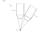
- a welding device 1 as a first embodiment of a welding device according to the present invention.
- the welding device 1 includes a first torch 11 and a second torch 12.
- Each of the first torch 11 and the second torch 12 emits a predetermined laser beam, and causes the laser beam to focus on a working point P.
- the laser beam emitted from the first torch 11 is referred to as a "first laser beam”
- the laser beam emitted from the second torch 12 is referred to as a "second laser beam”.
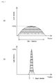
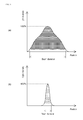
- Figs. 2(a) and 2(b) show a profile (light intensity distribution) of the first laser beam at the working point P and a profile (light intensity distribution) of the second laser beam at the working point P, respectively.
- a horizontal axis represents a position
- a vertical axis represents light intensity of each laser beam at the corresponding position
- a beam diameter of each laser beam is defined based on 86.5% of total output of each laser beam. Specifically, in the profile of each laser beam, an area occupying 86.5% of total output of each laser beam is calculated (see hatching-patterned portions in Figs. 2(a) and 2(b) ) from a portion, as a basic point, where the light intensity is a peak (100%), and a width of a portion having a minimum light intensity in the area is defined as a beam diameter of each laser beam.
- the beam diameter of the first laser beam is larger than that of the second laser beam.
- the first laser beam has the beam diameter of 0.85 mm
- the second laser beam has the beam diameter of 0.1 mm.
- a peak of the light intensity of the first laser beam is lower than a peak of the light intensity of the second laser beam.
- the total output (the internal area of the profile in Fig. 2(a) ) of the first laser beam is larger than the total output (the internal area of the profile in Fig. 2(b) ) of the second laser beam.
- the first laser beam has the total output of 2400 W
- the second laser beam has the total output of 300 W.
- the first and second laser beams focusing on the working point P are superimposed at the working point P.
- the first and second laser beams are superimposed at the working point P so that the beam center of the first laser beam and the beam center of the second laser beam coincide with each other.
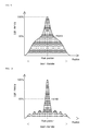
- Figs. 3 and 4 show a profile (light intensity distribution) of a laser beam formed by superimposing the first laser beam and the second laser beam at the working point P (hereinafter, referred to as a "superimposed laser beam").
- Fig. 3 shows a three-dimensional profile of the superimposed laser beam.
- an x-axis and a y-axis each represent a position
- a z-axis represents the light intensity of the superimposed laser beam at the corresponding position.
- Fig. 4 shows a two-dimensional profile of the superimposed laser beam.
- the horizontal axis represents a position
- the vertical axis represents the light intensity of the superimposed laser beam at the corresponding position.
- the beam diameter of the superimposed laser beam is defined based on 86.5% of the total output of the superimposed laser beam.
- the superimposed laser beam has the beam diameter of 0.80 mm and the total output of 2700 W.
- the profile of the superimposed laser beam has a shape in which the profile of the first laser beam and the profile of the second laser beam substantially overlap with each other.
- the profile of the superimposed laser beam has a relatively wide portion corresponding to the first laser beam and a relatively narrow portion corresponding to the second laser beam.
- the portion corresponding to the first laser beam has a power density allowing thermal-conduction type welding
- the portion corresponding to the second laser beam has a power density allowing keyhole type welding.
- the thermal-conduction type welding is a welding method in which the laser beam having a relatively low power density is used.
- a base material is melted by heat of the laser beam absorbed into the surface of the base material.
- the keyhole type welding is a welding method in which the laser beam having a relatively high power density is used.
- the welding is performed using a hole (keyhole) formed in a molten pool by a pressure of metallic vapor.
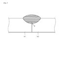
- Described below is an effect obtained in the case where a first workpiece W1 and a second workpiece W2 are welded with the welding device 1 capable of foiming the superimposed laser beam.
- the first workpiece W1 and the second workpiece W2 are objects to be welded by the welding device 1, and are formed in flat plates.
- the first workpiece W1 and the second workpiece W2 are arranged so that one side surface (right end face in Fig. 5 ) of the first workpiece W1 comes in contact with one side surface (left end face in Fig. 5 ) of the second workpiece W2.
- a molten pool M is formed in portions irradiated with the superimposed laser beam in the first workpiece W1 and the second workpiece W2, and a keyhole K is formed in the molten pool M.
- the profile of the superimposed laser beam includes the portion, having the power density allowing the thermal-conduction type welding, corresponding to the first laser beam, the molten pool M having a size corresponding to the beam diameter of the superimposed laser beam is formed in the portions irradiated with the superimposed laser beam in the first workpiece W1 and the second workpiece W2.
- the profile of the superimposed laser beam includes the portion, having the power density allowing the keyhole type welding, corresponding to the second laser beam, the keyhole K is formed in the molten pool M.
- Each of the first workpiece W1 and the second workpiece W2 is made of a material mainly containing aluminum, and an oxide film (alumina) is formed on the surface of each workpiece.
- Alumina that is of the oxide film of each workpiece has a melting point of approximately 2020°C, and the melting point of alumina is higher than the melting point (approximately 660°C) of aluminum.
- the oxide film of each workpiece is hardly melted directly by the laser beam. Since force of a thermal convection is small in a deep portion (portion surrounded by an ellipse D in Fig. 5 ) of the molten pool M, the oxide film of each workpiece is hardly broken by thermal convection.
- the superimposed laser beam makes the keyhole K in the molten pool M while foiming the molten pool M having the size corresponding to the beam diameter of the superimposed laser beam.
- the molten pool M is stirred by the keyhole K made by the pressure of the metallic vapor.
- the molten metal flows, thus enabling to suitably break the oxide film of each workpiece.
- the material mainly containing aluminum is used as the materials of the first workpiece W1 and the second workpiece W2.
- metal having a large difference between the melting point of the oxide film formed on the surface thereof and the melting point of the portion thereof (non-oxidized portion) inside the oxide film is preferably used in the present invention.
- the desired penetration depth is achieved by the keyhole, but in the present invention, the keyhole K is formed in order to stir the molten pool M after the molten pool M having such a size that the desired penetration depth (without consideration for the oxide film) can be secured.
- the profile of the superimposed laser beam is not limited as long as the molten pool M having such a size that the desired penetration depth (without consideration for the oxide film) can be secured and the keyhole K capable of stirring the molten pool M can be formed.
- the portion where the light intensity is 50% of the peak has the power density of 2000 kW/cm 2 or more.
- the portion corresponding to the second laser beam is the profile capable of forming the keyhole K in the molten pool M.
- the keyhole K capable of stirring the molten pool M is formed, thus enabling to suitably break the oxide film remaining in the deep portion of the molten pool M.
- the portion where the light intensity is 50% of the peak in the profile of the superimposed laser beam has the power density of 4000 kW/cm 2 .
- the position of the peak light intensity falls within a range of a quarter of the beam diameter from the center of a circle whose diameter corresponds to the beam diameter.
- the portion corresponding to the second laser beam is situated in the vicinity of the center of the profile of the superimposed laser beam.
- the keyhole K is formed in the vicinity of the center of the molten pool M, thus enabling to efficiently stirring the molten pool M.
- the peak position in the profile of the superimposed laser beam coincides with the center of the circle whose diameter corresponds to the beam diameter in the profile of the superimposed laser beam.
- a full width at half maximum (hereinafter, referred to as a "FWHM") is smaller than or equal to 30% of the beam diameter (a condition of 0 ⁇ (FWHM /beam diameter) ⁇ 0.3 holds).
- the FWHM means a width of the portion where the light intensity is 50% of the peak in the profile of the laser beam (see Fig. 4 ).
- the size of the molten pool M is proportional to the width of the portion corresponding to the first laser beam in the profile of the superimposed laser beam
- the size of the keyhole K is proportional to the width of the portion corresponding to the second laser beam in the profile of the superimposed laser beam. If the keyhole K is excessively large with respect to the molten pool M, part of the molten pool M may scatter to lead to a welding defect.
- the FWHM is smaller than or equal to 30% of the beam diameter in the profile of the superimposed laser beam.
- FWHM/beam diameter is 0.0625.
- the portion except the area which occupies 20% of the total output of the superimposed laser beam and which is calculated from the portion, as a basic point, where the light intensity is a peak (100%) has the total output of 1500 W or more in the profile of the superimposed laser beam.
- the portion corresponding to the first laser beam in the profile of the superimposed laser beam is a profile capable of foiming the molten pool M having such a size that the desired penetration depth (without consideration for the oxide film) can be secured.
- the total output of the portion is 2160 W.
- the first and second laser beams constituting the superimposed laser beam may be either a continuous wave or a pulse wave.
- the profile of the superimposed laser beam needs to become the shape in Figs. 3 and 4 during pulse output.
- the first workpiece W1 and the second workpiece W2 are irradiated with the superimposed laser beam so that the peak position in the profile of the superimposed laser beam is not located in the boundary portion (contact surface of each workpiece) between the first workpiece W1 and the second workpiece W2.
- the keyhole is formed at a position corresponding to the peak position in the profile of the laser beam.
- a blow hole (pore) that may remain in the welded portion after the welding is formed at the position where the keyhole is formed during the welding.
- the blow hole is coupled with a minute gap in the boundary portion.
- the penetration depth may become smaller than a desired value, which results in a risk of degrading strength of the welded portion.
- the peak position in the profile of the superimposed laser beam is shifted from the boundary portion between the first workpiece W1 and the second workpiece W2 by a predetermined distance (for example, 0.2 mm), thus enabling to restrain the degradation of the strength in the welded portion without the blow hole coupling with the minute gap in the boundary portion.
- a welding device 2 as a second embodiment of a welding device according to the present invention.
- the welding device 2 includes a first torch 21 and a second torch 22 (not shown).
- the first torch 21 and the second torch 22 are formed similarly to the first torch 11 and second torch 12 in the welding device 1, and cause a predetermined laser beam to focus on the working point P.
- the laser beam emitted from the first torch 21 is referred to as a "first laser beam”
- the laser beam emitted from the second torch 22 is referred to as a "second laser beam”.
- Figs. 8(a) and 8(b) show a profile (light intensity distribution) of the first laser beam at the working point P and a profile (light intensity distribution) of the second laser beam at the working point P, respectively.
- the horizontal axis represents the position
- the vertical axis represents the light intensity of each laser beam at the corresponding position.
- the beam diameter of the first laser beam is larger than that of the second laser beam.
- the first laser beam has the beam diameter of 0.45 mm
- the second laser beam has the beam diameter of 0.1 mm.
- the peak of the light intensity of the first laser beam is higher than that of the light intensity of the second laser beam.
- the total output (the internal area of the profile in Fig. 8(a) ) of the first laser beam is larger than the total output (the internal area of the profile in Fig. 8(b) ) of the second laser beam.
- the first laser beam has the total output of 2100 W
- the second laser beam has the total output of 150 W.
- the first and second laser beams focusing on the working point P are superimposed at the working point P.
- the first and second laser beams are superimposed at the working point P so that the beam center of the first laser beam and the beam center of the second laser beam coincide with each other.
- the portion where the light intensity is 50% of the peak has the power density of 2100 kW/cm 2 .
- FWHM/beam diameter is 0.238.
- the portion except the area which occupies 20% of the total output of the superimposed laser beam and which is calculated from the portion, as a basic point, where the light intensity is a peak (100%) has the total output of 1800 W in the profile of the superimposed laser beam in the present embodiment.
- the superimposed laser beam having the above-mentioned profile similarly to the superimposed laser beam formed by the welding device 1, makes it possible to achieve a desired penetration depth without the oxide film remaining in the deep portion of the molten pool when the plurality of base materials are welded.
- a welding device 3 as a third embodiment of a welding device according to the present invention.
- the welding device 3 includes a diffractive optical element (DOE) (not shown).
- DOE diffractive optical element
- a galvano-scanner may be used as the welding device 3 in addition to the torch generally used in the laser welding.
- the galvano-scanner is used as the welding device 3 from the viewpoint of improvement of a welding speed and flexibility of a scanning locus.
- the laser beam emitted from the welding device 3 is referred to as a "single laser beam”.
- Fig. 10 shows a profile (light intensity distribution) of the single laser beam.
- Fig. 10 shows the profile of the single laser beam.
- the horizontal axis represents the position
- the vertical axis represents the light intensity of the single laser beam at the corresponding position.
- the single laser beam has the beam diameter of 0.8 mm and the total output of 2200 W.
- the portion where the light intensity is 50% of the peak has the power density of 3500 kW/cm 2 .
- the peak position coincides with the center of the circle whose diameter corresponds to the beam diameter.
- FWHM/beam diameter 0.0625.
- the portion except the area which occupies 20% of the total output of the superimposed laser beam and which is calculated from the portion, as a basic point, where the light intensity is a peak (100%) has the total output of 1760 W in the profile of the single laser beam in the present embodiment.
- the welding device 3 can form the single laser beam having the profile similar to that of the superimposed laser beam formed by the welding device 1 or 2.
- the profile similar to that of the superimposed laser beam includes not only the profile completely identical to that of the superimposed laser beam but also the profile of the laser beam exerting the effect identical to that of the superimposed laser beam such as the single laser beam formed by the welding device 3.
- the single laser beam may be either a continuous wave or a pulse wave.
- a step for producing a battery 100 as an embodiment of a method for producing a battery according to the present invention.
- the step for producing the battery 100 includes a welding step in which the welding device 1 is used.
- the battery 100 is described below.
- the battery 100 is a sealed-type battery.
- the battery 100 includes a case 110.
- the case 110 is a container in which an electrode body (not shown) is stored together with an electrolyte solution, and is an object to be welded by the welding device 1.
- the electrode body is formed by laminating and winding a pair of electrodes (positive and negative electrodes) formed in a sheet shape with a separator interposed therebetween.
- the electrode body is impregnated with the electrolyte solution, thereby acting as a power-generating element.
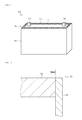
- the case 110 includes a storage part 111 and a lid part 112.
- the storage part 111 is a box having a substantially rectangular parallelepiped shape, and one surface (top face in Fig. 8 ) of the storage part 111 is open.
- the electrode body and the electrolyte solution are stored in the storage part 111.
- the lid part 112 is a flat plate that closes the open surface of the storage part 111.
- the lid part 112 has a shape corresponding to the open surface of the storage part 111, and is arranged to come into contact with an inner surface of the storage part 111.
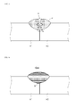
- the lid part 112 is joined to the storage part 111 by the laser welding using the welding device 1. Specifically, the boundary portion between the lid part 112 and the storage part 111 is melted by the superimposed laser beam emitted from the welding device 1. Then, the molten portion is solidified to form a welded portion 120, and the lid part 112 and the storage part 111 are joined to each other.
- the lid part 112 has two openings into which two terminals 130 are inserted, and the terminals 130 are fixed to the openings.
- the terminals 130 are members electrically connected to the electrode body.
- one end is electrically connected to the positive electrode of the electrode body, and the other end is arranged to protrude from the lid part 112 toward the outside of the case 110.
- one end is electrically connected to the negative electrode of the electrode body, and the other end is arranged to protrude from the lid part 112 toward the outside of the case 110.
- the welding step is performed after the electrode body is stored in the storage part 111 of the case 110.
- the welding step includes performing the laser welding with respect to the case 110 using the welding device 1.
- the storage part 111 and the lid part 112 are welded with the welding device 1 while filling the open surface of the storage part 111 with the lid part 112.
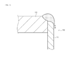
- the storage part 111 and the lid part 112 are welded with the welding device 1, preferably the storage part 111 and the lid part 112 are irradiated with the superimposed laser beam so that the peak position in the profile of the superimposed laser beam is located inside (left side in Fig. 9 ) the case 110 with respect to the boundary portion between the storage part 111 and the lid part 112.
- the peak position in the profile of the superimposed laser beam is preferably shifted inward of the case 110 from the boundary portion between the storage part 111 and the lid part 112 along the surface of the case 110 (upper end face of the case 110 in Fig. 9 ) irradiated with the superimposed laser beam.
- the peak position in the profile of the superimposed laser beam is shifted from the boundary portion between the storage part 111 and the lid part 112, thus enabling to restrain the degradation of the strength of the welded portion 120 in the case where the blow hole remains in the welded portion 120.
- the portion of the storage part 111 melted by the superimposed laser beam is a corner of the case 110. In the corner, the heat does not escape to atmosphere with thermal conductivity lower than that of the case 110 and easily stays during the welding.
- a thickness (a horizontal dimension in Fig. 10 ) of the storage part 111 is smaller than a thickness (a vertical dimension in Fig. 10 ) of the lid part 112.
- the peak position in the profile of the superimposed laser beam is shifted from the boundary portion between the storage part 111 and the lid part 112 to the inside of the case 110, thus enabling to restrain the storage part 111 from excessively melting.
- the welding device 2 or the welding device 3 may be used instead of the welding device 1.
- the present invention is applicable to a technique for restraining a welding defect in laser welding.
Landscapes
- Physics & Mathematics (AREA)
- Optics & Photonics (AREA)
- Engineering & Computer Science (AREA)
- Plasma & Fusion (AREA)
- Mechanical Engineering (AREA)
- Laser Beam Processing (AREA)
- Sealing Battery Cases Or Jackets (AREA)
Applications Claiming Priority (1)
| Application Number | Priority Date | Filing Date | Title |
|---|---|---|---|
| PCT/JP2012/065046 WO2013186862A1 (fr) | 2012-06-12 | 2012-06-12 | Dispositif de soudage, procédé de soudage et procédé de production de cellule |
Publications (2)
| Publication Number | Publication Date |
|---|---|
| EP2859986A1 true EP2859986A1 (fr) | 2015-04-15 |
| EP2859986A4 EP2859986A4 (fr) | 2016-02-24 |
Family
ID=49757726
Family Applications (1)
| Application Number | Title | Priority Date | Filing Date |
|---|---|---|---|
| EP12879057.3A Withdrawn EP2859986A4 (fr) | 2012-06-12 | 2012-06-12 | Dispositif de soudage, procédé de soudage et procédé de production de cellule |
Country Status (6)
| Country | Link |
|---|---|
| US (1) | US20150183058A1 (fr) |
| EP (1) | EP2859986A4 (fr) |
| JP (1) | JPWO2013186862A1 (fr) |
| KR (1) | KR20150016408A (fr) |
| CN (1) | CN104364044A (fr) |
| WO (1) | WO2013186862A1 (fr) |
Cited By (4)
| Publication number | Priority date | Publication date | Assignee | Title |
|---|---|---|---|---|
| WO2016198724A3 (fr) * | 2015-06-09 | 2017-04-20 | Corelase Oy | Appareil et procédé de traitement au laser et composant optique destiné à ceux-ci |
| DE102016220067A1 (de) * | 2016-10-14 | 2018-04-19 | Technische Universität Ilmenau | Verfahren zum Tiefschweißen eines Werkstücks, wobei eine verkippte Dampfkapillare mittels zweier Laserstrahlen erzeugt wird |
| EP3826083A4 (fr) * | 2018-07-18 | 2022-07-27 | Samsung SDI Co., Ltd. | Batterie rechargeable et procédé de soudage de batterie rechargeable |
| US11850679B2 (en) | 2017-12-29 | 2023-12-26 | Corelase Oy | Laser processing apparatus and method |
Families Citing this family (14)
| Publication number | Priority date | Publication date | Assignee | Title |
|---|---|---|---|---|
| JP6071010B2 (ja) * | 2014-01-30 | 2017-02-01 | トヨタ自動車株式会社 | 溶接方法 |
| JP6476941B2 (ja) * | 2015-02-05 | 2019-03-06 | 株式会社Gsユアサ | 蓄電素子、蓄電素子を備えた蓄電装置、蓄電素子の製造方法、及び蓄電装置の製造方法 |
| US11130196B2 (en) * | 2017-03-30 | 2021-09-28 | Nio Usa, Inc. | Single-position sequential laser welding system |
| JP6974957B2 (ja) * | 2017-03-31 | 2021-12-01 | 日本ケミコン株式会社 | アルミ材のレーザキーホール溶接構造及びレーザキーホール溶接方法 |
| JP6863050B2 (ja) | 2017-04-28 | 2021-04-21 | トヨタ自動車株式会社 | レーザ溶接方法及びレーザ溶接装置 |
| US10786872B2 (en) * | 2017-06-15 | 2020-09-29 | Toyota Jidosha Kabushiki Kaisha | Welding method |
| JP6852588B2 (ja) | 2017-06-20 | 2021-03-31 | トヨタ自動車株式会社 | レーザ溶接方法及びレーザ溶接装置 |
| JP6674422B2 (ja) * | 2017-09-14 | 2020-04-01 | フタバ産業株式会社 | レーザ溶接装置、及び、部材の製造方法 |
| JP6989549B2 (ja) * | 2019-03-13 | 2022-01-05 | フタバ産業株式会社 | 接合体の製造方法 |
| US12597660B2 (en) | 2020-04-10 | 2026-04-07 | Lg Energy Solution, Ltd. | Battery module and method of manufacturing the same |
| CN112496614B (zh) * | 2020-12-17 | 2022-09-13 | 上海工程技术大学 | 一种深熔焊的有限元仿真热源模型获取方法 |
| CN114406470B (zh) * | 2022-01-26 | 2025-02-14 | 中国航空制造技术研究院 | 排气管筒体与法兰的双光束激光焊接方法 |
| CN116618831A (zh) * | 2022-02-11 | 2023-08-22 | 本田技研工业株式会社 | 接合部件的制造方法 |
| JP2024151458A (ja) * | 2023-04-12 | 2024-10-25 | プライムプラネットエナジー&ソリューションズ株式会社 | 電池セルおよびその製造方法 |
Family Cites Families (19)
| Publication number | Priority date | Publication date | Assignee | Title |
|---|---|---|---|---|
| US6087619A (en) * | 1997-05-13 | 2000-07-11 | Fraunhofer Usa Resource Center | Dual intensity multi-beam welding system |
| AU9155698A (en) * | 1997-08-01 | 1999-02-22 | Fraunhofer-Gesellschaft Zur Forderung Der Angewandten Forschung E.V. | Method and device for laser beam welding |
| JP2002210576A (ja) * | 2001-01-16 | 2002-07-30 | Nippon Steel Corp | 合成yagレーザによる薄手鋼板の溶接方法 |
| DE10214949C1 (de) * | 2002-04-04 | 2003-11-20 | Hydro Aluminium Deutschland | Verfahren und Vorrichtung zum Strahlschweißen |
| JP2004337881A (ja) * | 2003-05-13 | 2004-12-02 | Matsushita Electric Ind Co Ltd | レーザ加工方法およびレーザ加工装置 |
| JP2004358521A (ja) * | 2003-06-05 | 2004-12-24 | Mitsubishi Heavy Ind Ltd | レーザ熱加工装置、レーザ熱加工方法 |
| US7479616B2 (en) * | 2004-04-20 | 2009-01-20 | General Motors Corporation | Compound laser beam welding |
| CN1785575B (zh) * | 2004-12-08 | 2010-11-10 | 松下电器产业株式会社 | 混合激光加工方法及该方法所用的混合激光头 |
| JP4929606B2 (ja) * | 2005-03-16 | 2012-05-09 | トヨタ自動車株式会社 | 密閉型蓄電装置及びその製造方法 |
| JP4822737B2 (ja) * | 2005-04-22 | 2011-11-24 | ミヤチテクノス株式会社 | レーザ溶接方法及びレーザ溶接装置 |
| JP2007319878A (ja) * | 2006-05-31 | 2007-12-13 | Mitsubishi Heavy Ind Ltd | レーザ加工装置及びレーザ加工方法 |
| US8803029B2 (en) * | 2006-08-03 | 2014-08-12 | Chrysler Group Llc | Dual beam laser welding head |
| EP2081728B1 (fr) * | 2006-10-30 | 2012-06-13 | Flemming Ove Elholm Olsen | Procédé et système de traitement laser |
| FR2908677B1 (fr) * | 2006-11-17 | 2009-02-20 | Air Liquide | Procede de soudage par faisceau laser a penetration amelioree |
| JP5105944B2 (ja) * | 2007-04-16 | 2012-12-26 | パナソニック株式会社 | レーザ装置 |
| JP5466903B2 (ja) * | 2009-08-28 | 2014-04-09 | 本田技研工業株式会社 | 溶接方法 |
| JP5479024B2 (ja) * | 2009-10-27 | 2014-04-23 | パナソニック株式会社 | 接合方法および接合装置 |
| JP5595139B2 (ja) | 2010-06-23 | 2014-09-24 | 三菱重工業株式会社 | 溶接方法及び溶接システム |
| JP5570396B2 (ja) * | 2010-11-22 | 2014-08-13 | パナソニック株式会社 | 溶接方法および溶接装置 |
-
2012
- 2012-06-12 EP EP12879057.3A patent/EP2859986A4/fr not_active Withdrawn
- 2012-06-12 CN CN201280073896.5A patent/CN104364044A/zh active Pending
- 2012-06-12 JP JP2014520848A patent/JPWO2013186862A1/ja active Pending
- 2012-06-12 US US14/407,193 patent/US20150183058A1/en not_active Abandoned
- 2012-06-12 KR KR1020157000391A patent/KR20150016408A/ko not_active Ceased
- 2012-06-12 WO PCT/JP2012/065046 patent/WO2013186862A1/fr not_active Ceased
Cited By (8)
| Publication number | Priority date | Publication date | Assignee | Title |
|---|---|---|---|---|
| WO2016198724A3 (fr) * | 2015-06-09 | 2017-04-20 | Corelase Oy | Appareil et procédé de traitement au laser et composant optique destiné à ceux-ci |
| US10807190B2 (en) | 2015-06-09 | 2020-10-20 | Corelase Oy | Laser processing apparatus and method and an optical component therefor |
| DE102016220067A1 (de) * | 2016-10-14 | 2018-04-19 | Technische Universität Ilmenau | Verfahren zum Tiefschweißen eines Werkstücks, wobei eine verkippte Dampfkapillare mittels zweier Laserstrahlen erzeugt wird |
| DE102016220067B4 (de) | 2016-10-14 | 2023-09-21 | Trumpf Laser Und Systemtechnik Gmbh | Verfahren zum Tiefschweißen eines Werkstücks, wobei eine verkippte Dampfkapillare mittels zweier Laserstrahlen erzeugt wird |
| US11850679B2 (en) | 2017-12-29 | 2023-12-26 | Corelase Oy | Laser processing apparatus and method |
| US12447553B2 (en) | 2017-12-29 | 2025-10-21 | Corelase Oy | Laser processing apparatus and method |
| EP3826083A4 (fr) * | 2018-07-18 | 2022-07-27 | Samsung SDI Co., Ltd. | Batterie rechargeable et procédé de soudage de batterie rechargeable |
| US12218363B2 (en) | 2018-07-18 | 2025-02-04 | Samsung Sdi Co., Ltd. | Rechargeable battery and method for welding rechargeable battery |
Also Published As
| Publication number | Publication date |
|---|---|
| CN104364044A (zh) | 2015-02-18 |
| WO2013186862A1 (fr) | 2013-12-19 |
| JPWO2013186862A1 (ja) | 2016-02-01 |
| KR20150016408A (ko) | 2015-02-11 |
| US20150183058A1 (en) | 2015-07-02 |
| EP2859986A4 (fr) | 2016-02-24 |
Similar Documents
| Publication | Publication Date | Title |
|---|---|---|
| EP2859986A1 (fr) | Dispositif de soudage, procédé de soudage et procédé de production de cellule | |
| KR101213309B1 (ko) | 밀폐형 이차 전지 및 그 제조 방법 | |
| JP7695398B2 (ja) | レーザー溶接が適用された円筒形二次電池とその製造方法、このような二次電池を含むバッテリーパック及び自動車 | |
| JP6536885B2 (ja) | 電池容器の製造方法および電池容器 | |
| JP2011076776A (ja) | 電極体の芯体露出部と集電用部材との溶接方法 | |
| JPWO2010131298A1 (ja) | レーザ溶接方法及びそれを含む電池の製造方法 | |
| JP2017098565A5 (fr) | ||
| JP5884692B2 (ja) | レーザ溶接方法 | |
| US11203085B2 (en) | Method and apparatus for laser welding | |
| JP2012130946A (ja) | ケースの溶接方法 | |
| US20060207085A1 (en) | Battery and method for manufacturing same | |
| KR101838382B1 (ko) | 밀폐형 전지 및 그 제조 방법 | |
| US11123817B2 (en) | Method of welding laminated metal foils | |
| JP2016143656A (ja) | 蓄電素子、蓄電素子を備えた蓄電装置、蓄電素子の製造方法、及び蓄電装置の製造方法 | |
| JP2010097770A (ja) | 電池筐体、二次電池及び二次電池の製造方法 | |
| JP2013122973A (ja) | 金属箔の接続構造及びその接続方法及びコンデンサ | |
| US11458568B2 (en) | Laser processing method | |
| JP2015011785A (ja) | 蓄電装置及び該蓄電装置の製造方法 | |
| JP7535721B2 (ja) | レーザ加工方法およびレーザ加工装置 | |
| US20160285068A1 (en) | Method for mechanical treatment of an electrical connection part for a secondary cell | |
| JP5937483B2 (ja) | 電池及び電池の製造方法 | |
| WO2017073744A1 (fr) | Procédé de fabrication d'ensemble à électrodes, et ensemble à électrodes | |
| JP6613813B2 (ja) | 電極組立体の製造方法および電極組立体 | |
| JP2015147220A (ja) | レーザ溶接方法 | |
| JP5991148B2 (ja) | 蓄電装置 |
Legal Events
| Date | Code | Title | Description |
|---|---|---|---|
| PUAI | Public reference made under article 153(3) epc to a published international application that has entered the european phase |
Free format text: ORIGINAL CODE: 0009012 |
|
| 17P | Request for examination filed |
Effective date: 20141218 |
|
| AK | Designated contracting states |
Kind code of ref document: A1 Designated state(s): AL AT BE BG CH CY CZ DE DK EE ES FI FR GB GR HR HU IE IS IT LI LT LU LV MC MK MT NL NO PL PT RO RS SE SI SK SM TR |
|
| AX | Request for extension of the european patent |
Extension state: BA ME |
|
| DAX | Request for extension of the european patent (deleted) | ||
| RA4 | Supplementary search report drawn up and despatched (corrected) |
Effective date: 20160122 |
|
| RIC1 | Information provided on ipc code assigned before grant |
Ipc: B23K 26/20 20140101ALI20160118BHEP Ipc: B23K 26/26 20140101AFI20160118BHEP |
|
| STAA | Information on the status of an ep patent application or granted ep patent |
Free format text: STATUS: THE APPLICATION IS DEEMED TO BE WITHDRAWN |
|
| 18D | Application deemed to be withdrawn |
Effective date: 20160820 |