EP2859987A1 - Bauteilverbund - Google Patents
Bauteilverbund Download PDFInfo
- Publication number
- EP2859987A1 EP2859987A1 EP20130187685 EP13187685A EP2859987A1 EP 2859987 A1 EP2859987 A1 EP 2859987A1 EP 20130187685 EP20130187685 EP 20130187685 EP 13187685 A EP13187685 A EP 13187685A EP 2859987 A1 EP2859987 A1 EP 2859987A1
- Authority
- EP
- European Patent Office
- Prior art keywords
- component
- connecting piece
- reactive
- welded
- assembly according
- Prior art date
- Legal status (The legal status is an assumption and is not a legal conclusion. Google has not performed a legal analysis and makes no representation as to the accuracy of the status listed.)
- Granted
Links
Images


Classifications
-
- B—PERFORMING OPERATIONS; TRANSPORTING
- B23—MACHINE TOOLS; METAL-WORKING NOT OTHERWISE PROVIDED FOR
- B23K—SOLDERING OR UNSOLDERING; WELDING; CLADDING OR PLATING BY SOLDERING OR WELDING; CUTTING BY APPLYING HEAT LOCALLY, e.g. FLAME CUTTING; WORKING BY LASER BEAM
- B23K35/00—Rods, electrodes, materials, or media, for use in soldering, welding, or cutting
- B23K35/02—Rods, electrodes, materials, or media, for use in soldering, welding, or cutting characterised by mechanical features, e.g. shape
- B23K35/0222—Rods, electrodes, materials, or media, for use in soldering, welding, or cutting characterised by mechanical features, e.g. shape for use in soldering or brazing
- B23K35/0233—Sheets or foils
- B23K35/0238—Sheets or foils layered
-
- B—PERFORMING OPERATIONS; TRANSPORTING
- B32—LAYERED PRODUCTS
- B32B—LAYERED PRODUCTS, i.e. PRODUCTS BUILT-UP OF STRATA OF FLAT OR NON-FLAT, e.g. CELLULAR OR HONEYCOMB, FORM
- B32B7/00—Layered products characterised by the relation between layers; Layered products characterised by the relative orientation of features between layers, or by the relative values of a measurable parameter between layers, i.e. products comprising layers having different physical, chemical or physicochemical properties; Layered products characterised by the interconnection of layers
- B32B7/04—Interconnection of layers
- B32B7/08—Interconnection of layers by mechanical means
-
- B—PERFORMING OPERATIONS; TRANSPORTING
- B32—LAYERED PRODUCTS
- B32B—LAYERED PRODUCTS, i.e. PRODUCTS BUILT-UP OF STRATA OF FLAT OR NON-FLAT, e.g. CELLULAR OR HONEYCOMB, FORM
- B32B7/00—Layered products characterised by the relation between layers; Layered products characterised by the relative orientation of features between layers, or by the relative values of a measurable parameter between layers, i.e. products comprising layers having different physical, chemical or physicochemical properties; Layered products characterised by the interconnection of layers
- B32B7/04—Interconnection of layers
- B32B7/12—Interconnection of layers using interposed adhesives or interposed materials with bonding properties
-
- B—PERFORMING OPERATIONS; TRANSPORTING
- B29—WORKING OF PLASTICS; WORKING OF SUBSTANCES IN A PLASTIC STATE IN GENERAL
- B29C—SHAPING OR JOINING OF PLASTICS; SHAPING OF MATERIAL IN A PLASTIC STATE, NOT OTHERWISE PROVIDED FOR; AFTER-TREATMENT OF THE SHAPED PRODUCTS, e.g. REPAIRING
- B29C65/00—Joining or sealing of preformed parts, e.g. welding of plastics materials; Apparatus therefor
- B29C65/56—Joining or sealing of preformed parts, e.g. welding of plastics materials; Apparatus therefor using mechanical means or mechanical connections, e.g. form-fits
- B29C65/562—Joining or sealing of preformed parts, e.g. welding of plastics materials; Apparatus therefor using mechanical means or mechanical connections, e.g. form-fits using extra joining elements, i.e. which are not integral with the parts to be joined
- B29C65/564—Joining or sealing of preformed parts, e.g. welding of plastics materials; Apparatus therefor using mechanical means or mechanical connections, e.g. form-fits using extra joining elements, i.e. which are not integral with the parts to be joined hidden in the joint, e.g. dowels or Z-pins
-
- B—PERFORMING OPERATIONS; TRANSPORTING
- B29—WORKING OF PLASTICS; WORKING OF SUBSTANCES IN A PLASTIC STATE IN GENERAL
- B29C—SHAPING OR JOINING OF PLASTICS; SHAPING OF MATERIAL IN A PLASTIC STATE, NOT OTHERWISE PROVIDED FOR; AFTER-TREATMENT OF THE SHAPED PRODUCTS, e.g. REPAIRING
- B29C66/00—General aspects of processes or apparatus for joining preformed parts
- B29C66/01—General aspects dealing with the joint area or with the area to be joined
- B29C66/05—Particular design of joint configurations
- B29C66/10—Particular design of joint configurations particular design of the joint cross-sections
- B29C66/11—Joint cross-sections comprising a single joint-segment, i.e. one of the parts to be joined comprising a single joint-segment in the joint cross-section
- B29C66/112—Single lapped joints
- B29C66/1122—Single lap to lap joints, i.e. overlap joints
-
- B—PERFORMING OPERATIONS; TRANSPORTING
- B29—WORKING OF PLASTICS; WORKING OF SUBSTANCES IN A PLASTIC STATE IN GENERAL
- B29C—SHAPING OR JOINING OF PLASTICS; SHAPING OF MATERIAL IN A PLASTIC STATE, NOT OTHERWISE PROVIDED FOR; AFTER-TREATMENT OF THE SHAPED PRODUCTS, e.g. REPAIRING
- B29C66/00—General aspects of processes or apparatus for joining preformed parts
- B29C66/01—General aspects dealing with the joint area or with the area to be joined
- B29C66/05—Particular design of joint configurations
- B29C66/20—Particular design of joint configurations particular design of the joint lines, e.g. of the weld lines
- B29C66/21—Particular design of joint configurations particular design of the joint lines, e.g. of the weld lines said joint lines being formed by a single dot or dash or by several dots or dashes, i.e. spot joining or spot welding
-
- B—PERFORMING OPERATIONS; TRANSPORTING
- B29—WORKING OF PLASTICS; WORKING OF SUBSTANCES IN A PLASTIC STATE IN GENERAL
- B29C—SHAPING OR JOINING OF PLASTICS; SHAPING OF MATERIAL IN A PLASTIC STATE, NOT OTHERWISE PROVIDED FOR; AFTER-TREATMENT OF THE SHAPED PRODUCTS, e.g. REPAIRING
- B29C66/00—General aspects of processes or apparatus for joining preformed parts
- B29C66/40—General aspects of joining substantially flat articles, e.g. plates, sheets or web-like materials; Making flat seams in tubular or hollow articles; Joining single elements to substantially flat surfaces
- B29C66/41—Joining substantially flat articles ; Making flat seams in tubular or hollow articles
- B29C66/43—Joining a relatively small portion of the surface of said articles
-
- B—PERFORMING OPERATIONS; TRANSPORTING
- B29—WORKING OF PLASTICS; WORKING OF SUBSTANCES IN A PLASTIC STATE IN GENERAL
- B29C—SHAPING OR JOINING OF PLASTICS; SHAPING OF MATERIAL IN A PLASTIC STATE, NOT OTHERWISE PROVIDED FOR; AFTER-TREATMENT OF THE SHAPED PRODUCTS, e.g. REPAIRING
- B29C66/00—General aspects of processes or apparatus for joining preformed parts
- B29C66/70—General aspects of processes or apparatus for joining preformed parts characterised by the composition, physical properties or the structure of the material of the parts to be joined; Joining with non-plastics material
- B29C66/72—General aspects of processes or apparatus for joining preformed parts characterised by the composition, physical properties or the structure of the material of the parts to be joined; Joining with non-plastics material characterised by the structure of the material of the parts to be joined
- B29C66/721—Fibre-reinforced materials
-
- B—PERFORMING OPERATIONS; TRANSPORTING
- B29—WORKING OF PLASTICS; WORKING OF SUBSTANCES IN A PLASTIC STATE IN GENERAL
- B29C—SHAPING OR JOINING OF PLASTICS; SHAPING OF MATERIAL IN A PLASTIC STATE, NOT OTHERWISE PROVIDED FOR; AFTER-TREATMENT OF THE SHAPED PRODUCTS, e.g. REPAIRING
- B29C66/00—General aspects of processes or apparatus for joining preformed parts
- B29C66/70—General aspects of processes or apparatus for joining preformed parts characterised by the composition, physical properties or the structure of the material of the parts to be joined; Joining with non-plastics material
- B29C66/74—Joining plastics material to non-plastics material
- B29C66/742—Joining plastics material to non-plastics material to metals or their alloys
-
- B—PERFORMING OPERATIONS; TRANSPORTING
- B32—LAYERED PRODUCTS
- B32B—LAYERED PRODUCTS, i.e. PRODUCTS BUILT-UP OF STRATA OF FLAT OR NON-FLAT, e.g. CELLULAR OR HONEYCOMB, FORM
- B32B15/00—Layered products comprising a layer of metal
- B32B15/04—Layered products comprising a layer of metal comprising metal as the main or only constituent of a layer, which is next to another layer of the same or of a different material
- B32B15/08—Layered products comprising a layer of metal comprising metal as the main or only constituent of a layer, which is next to another layer of the same or of a different material of synthetic resin
-
- B—PERFORMING OPERATIONS; TRANSPORTING
- B32—LAYERED PRODUCTS
- B32B—LAYERED PRODUCTS, i.e. PRODUCTS BUILT-UP OF STRATA OF FLAT OR NON-FLAT, e.g. CELLULAR OR HONEYCOMB, FORM
- B32B37/00—Methods or apparatus for laminating, e.g. by curing or by ultrasonic bonding
- B32B37/12—Methods or apparatus for laminating, e.g. by curing or by ultrasonic bonding characterised by using adhesives
-
- F—MECHANICAL ENGINEERING; LIGHTING; HEATING; WEAPONS; BLASTING
- F16—ENGINEERING ELEMENTS AND UNITS; GENERAL MEASURES FOR PRODUCING AND MAINTAINING EFFECTIVE FUNCTIONING OF MACHINES OR INSTALLATIONS; THERMAL INSULATION IN GENERAL
- F16B—DEVICES FOR FASTENING OR SECURING CONSTRUCTIONAL ELEMENTS OR MACHINE PARTS TOGETHER, e.g. NAILS, BOLTS, CIRCLIPS, CLAMPS, CLIPS OR WEDGES; JOINTS OR JOINTING
- F16B5/00—Joining sheets or plates, e.g. panels, to one another or to strips or bars parallel to them
- F16B5/08—Joining sheets or plates, e.g. panels, to one another or to strips or bars parallel to them by means of welds or the like
-
- B—PERFORMING OPERATIONS; TRANSPORTING
- B32—LAYERED PRODUCTS
- B32B—LAYERED PRODUCTS, i.e. PRODUCTS BUILT-UP OF STRATA OF FLAT OR NON-FLAT, e.g. CELLULAR OR HONEYCOMB, FORM
- B32B2605/00—Vehicles
-
- Y—GENERAL TAGGING OF NEW TECHNOLOGICAL DEVELOPMENTS; GENERAL TAGGING OF CROSS-SECTIONAL TECHNOLOGIES SPANNING OVER SEVERAL SECTIONS OF THE IPC; TECHNICAL SUBJECTS COVERED BY FORMER USPC CROSS-REFERENCE ART COLLECTIONS [XRACs] AND DIGESTS
- Y10—TECHNICAL SUBJECTS COVERED BY FORMER USPC
- Y10T—TECHNICAL SUBJECTS COVERED BY FORMER US CLASSIFICATION
- Y10T156/00—Adhesive bonding and miscellaneous chemical manufacture
- Y10T156/10—Methods of surface bonding and/or assembly therefor
-
- Y—GENERAL TAGGING OF NEW TECHNOLOGICAL DEVELOPMENTS; GENERAL TAGGING OF CROSS-SECTIONAL TECHNOLOGIES SPANNING OVER SEVERAL SECTIONS OF THE IPC; TECHNICAL SUBJECTS COVERED BY FORMER USPC CROSS-REFERENCE ART COLLECTIONS [XRACs] AND DIGESTS
- Y10—TECHNICAL SUBJECTS COVERED BY FORMER USPC
- Y10T—TECHNICAL SUBJECTS COVERED BY FORMER US CLASSIFICATION
- Y10T29/00—Metal working
- Y10T29/49—Method of mechanical manufacture
- Y10T29/49826—Assembling or joining
-
- Y—GENERAL TAGGING OF NEW TECHNOLOGICAL DEVELOPMENTS; GENERAL TAGGING OF CROSS-SECTIONAL TECHNOLOGIES SPANNING OVER SEVERAL SECTIONS OF THE IPC; TECHNICAL SUBJECTS COVERED BY FORMER USPC CROSS-REFERENCE ART COLLECTIONS [XRACs] AND DIGESTS
- Y10—TECHNICAL SUBJECTS COVERED BY FORMER USPC
- Y10T—TECHNICAL SUBJECTS COVERED BY FORMER US CLASSIFICATION
- Y10T428/00—Stock material or miscellaneous articles
- Y10T428/19—Sheets or webs edge spliced or joined
- Y10T428/192—Sheets or webs coplanar
Definitions
- the present invention relates to a component assembly comprising a first component and a second component, further comprising at least one connector.
- the connecting piece penetrates the first component at least over the entire thickness of the first component.
- Such component composites can be used, for example, as composites of plastic or fiber composite panels in vehicle construction. It is customary to glue the components together, to rivet or to press them thermally. However, the quality of the known adhesive and pressing compounds, especially in industrial production in large quantities often poor or inconsistent. Some connection methods are only complicated or even not applicable if the accessibility for required tools, such as welding equipment, is not given. Especially in welding processes, it can lead to undesirably high thermal loads on the components to be joined. Also, the production of a large number of connection points between two components can take a long time if the connection points can only be produced consecutively in time.
- Nanofoils are made of alternating layers of often thousands of aluminum and nickel foils The smallest material thickness can be placed between the components to be joined and generate well localized process heat when activated.
- a component assembly comprising a first component and a second component, further comprising at least one connector, wherein the connector penetrates at least over the entire thickness of the first component, the first component, wherein the connector at its end facing the second component with the second component or with a second component defined further connecting piece by means of a reactive film, in particular a nanofoil, is welded.
- An inventive method for producing a component composite provides that the connecting piece is introduced into the first component and then the connector at its second component end facing the second component or with a second component defined further connector by means of a reactive film, in particular one Nanofoil, is welded.
- the first component for example a fiber-reinforced plastic plate, at least one - preferably also many- connector on that is driven by the first component or was already incorporated in the manufacture of the first component in this.
- This connector may for example be optimized by the choice of a suitable material to be connected by means of a reactive foil which is applied to a surface of the connector with a second component.
- the connecting piece is joined directly to the second component by means of the reactive foil or also indirectly joined to the second component via a further connecting piece.
- the further connecting piece can in particular penetrate the second component and can for example be of the same design as the connecting piece which penetrates the first component.
- the connecting piece that penetrates the first component also penetrates the second component almost or completely
- the connecting piece may be welded to the surface of the second component facing away from the first component.
- another connecting piece for example a disk covering the opening on the side of the second component facing away from the first component by means of a connecting piece penetrating the second component, and the reactive film being positioned between the connecting piece and the further connecting piece or disk can be positioned there be welded.
- a component assembly according to the invention can use components and connecting pieces which would be stressed too much by other joining methods.
- the reactive film in many positions for example be used on many connectors, and so provide a component network with a large number of connection points with uniformly high quality.
- the first component is a plate or a molded part and / or the second component is a plate or a molded part.
- Under plate or molding are not only flat or substantially in a plane extending parts to understand, but also structural components or shaped parts such as pressed, forged and tensile parts or profile bars or sheet metal forms or locally crushed tubes or molds and the like.
- connection pieces in the first component there are a plurality of connecting pieces in the first component, each penetrating over the entire thickness of the first component, the first component and at its second component end facing the second component or with the second component defined further connecting pieces by means of a respective reactive film, in particular one Nanofoil, are welded.
- a respective reactive film in particular one Nanofoil
- the connector may be cylindrical, pin-shaped or formed as a pin with a head, as well as possibly the other connector, which may also be designed as a disc or plate. Shapes without head are particularly suitable for connections of three components, where the first component so on the one hand with a second component and at the other end of the connector with a third component, or, for example, a disk is welded. Forms of the connecting piece with head are in turn particularly suitable for only one-sided welding of the connecting piece, wherein the head on the opposite side of the first component can abut against this and secure the first component at this end against axial displacement.
- the connecting piece and / or the further connecting piece may preferably consist of metal, in particular of non-ferrous metal, steel or aluminum or else of plastic.
- the first component made of plastic or fiber composite and is in particular a plastic plate or a fiber composite plate.
- the second component made of metal or plastic or of a fiber composite material and is in particular a metal plate, a metal sheet, a plastic plate or a fiber composite plate.
- connection between different materials namely in particular between plastic or fiber composite on one side and metal on the other side can be produced.
- the reactive film preferably has an adhesive layer on its underside and / or on its upper side. Thus, the reactive film can be easily adhered to a connector.
- the area of the reactive film is preferably smaller than the contact surface of the connecting piece on the second component or on the further connecting piece fixed to the second component.
- the connector is cohesively and / or positively connected to the first component, in particular rotatably connected.
- the further connector is cohesively and / or positively fixed to the second component or the further connection piece rests on the second component and is not fixed by its fusion with the first component penetrating connector frictionally on the second component.
- the connecting piece is cylindrical or pin-shaped and welded at one end to the second component and at the opposite end to a third component, in particular at both ends with a metal sheet.
- the connecting piece is designed as a pin with a head and at the end at which the connecting piece has no head, welded to the second component, in particular a metal sheet.
- the connecting piece is designed as a pin with a head and at the end at which the connecting piece has no head, welded to a second component penetrating another connector.
- one or more additional components in addition to the first component, one or more additional components, in particular further plates or molded parts, can be arranged on the connecting piece, so that the connecting piece penetrates the latter at least over the entire thickness of the first component and the additional components.
- the connector can then be welded to the second component and optionally also at the other end with a third component.
- a plurality of, in particular many, connecting pieces can be introduced into the first component and then the second component can be positioned relative to the first component and then the connecting pieces with the second component and / or with further connecting pieces fixed on the second component a reactive film, in particular a nanofoil, are welded.
- a reactive film in particular a nanofoil
- a separate reactive film is used on each connector.
- a common reactive film may be used for a plurality of connectors, wherein the composition of the film may be locally different, adapted to the positions of the connectors or for the transmission of the ignition energy.
- the reactive film which is common to a plurality of connecting pieces can be embodied such that it generates locally different process energies or process heat after activation, so that in areas in which no connecting pieces are arranged between the components, uncritical or lower process energies or Produces process heat and generated in areas where the connectors are higher or for the welding of components and connectors sufficient process energies or process heat.
- the reactive foils are preferably applied by machine to the connecting pieces in the first component.
- the reactive films may be removed from a suitable device to a set of nanofoils which may be provided on a non-electrically conductive carrier film and adhered to the connectors.
- Temperature entry, pressure or electrical voltage can be used to activate the reactive foils. It is particularly efficient when reactive films are activated at several connectors at the same time.
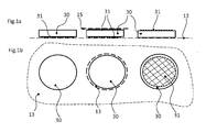
- reactive films 30 are shown, which can be used for a method according to the invention for producing a composite component.
- Several reactive films 30 are arranged for transport on a thin, electrically non-conductive carrier film 13.
- the reactive foils 30 are already equipped on one or two sides with an adhesive layer 31, which simplifies the subsequent sticking to a connecting piece.
- On the adhesive layer 31 in the middle of Fig. 1a shown reactive film 30 is a cover 15 is applied.
- the reactive foils 30 are round and are therefore particularly suitable for application to connecting pieces with a round cross section.
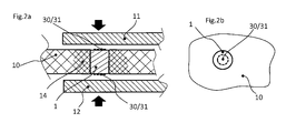
- Fig. 2a shows a composite component according to the invention before joining.
- a cylindrical connector 1 is introduced, with glued at both ends of reactive films 30.
- the height of the connector 1 corresponds approximately to the height of the first component 10, wherein upon activation of the reactive film 30 by pressure, the height of the connecting piece 1 is chosen rather larger, so may protrude beyond the first component 10, when activated by means of temperature or electrical voltage slightly smaller, but at least corresponding to the thickness of the first component 10 minus the thickness of the reactive film 30.
- the reactive film 30 By activating the reactive film 30, for example by pressure in the direction of the arrows shown or by temperature, two metal sheets are fixed as a second or third component 11, 12 on both sides of the first component 10 at this.
- the connecting piece 1 is woven into the first component 10, so that there is a compression 14 of the fibers in the region around the connecting piece 1.
- Fig. 2b shows a plan view of the fiber-reinforced plastic plate as the first component 10 with the introduced round connector 1 and reactive film 30 with adhesive layer 31.
- the reactive film 30 has a smaller radius than the connector. 1
- Fig. 3 shows the component composite accordingly Fig. 2a after the joining process. Between the first component 10 and the second or third component 11, 12 each weld zones 21 are formed.
- FIG. 5 are each embodiments of a composite component with a first component 10 and only one side of the first component 10 a joined second component 11, for example, a metal sheet.
- a connector 2 which is designed as a pin with head and at the end to which the connector 2 has no head, is welded to the second component 11 and forms a weld zone 21 there.
- the head of the connecting piece rest on the first component 10, Fig. 4 , or even flush with the first component 10, Fig. 5 ,
- a first component 10 is connected to a second component 11 such that in the first component 10, a connector 2 is designed as a pin head and at the end to which the connector 2 has no head, the connector 2 with a second component 11th penetrating another connector 4 is welded.
- Both components 10, 11 therefore already have before joining introduced, for example mitge necessarilyne connecting pieces 2, 4, so that they each have densifications 14 around the connecting pieces.
- Both components 10, 11 may be fiber-reinforced plastic sheets.
Landscapes
- Engineering & Computer Science (AREA)
- Mechanical Engineering (AREA)
- General Engineering & Computer Science (AREA)
- Connection Of Plates (AREA)
- Lining Or Joining Of Plastics Or The Like (AREA)
- Body Structure For Vehicles (AREA)
Abstract
Description
- Die vorliegende Erfindung betrifft einen Bauteilverbund umfassend einen ersten Bauteil und einen zweiten Bauteil, weiters umfassend zumindest ein Verbindungsstück. Das Verbindungsstück durchdringt zumindest über die gesamte Dicke des ersten Bauteils den ersten Bauteil.
- Derartige Bauteilverbunde können beispielsweise als Verbunde von Kunststoff- oder Faserverbundplatten im Fahrzeugbau verwendet werden. Üblich ist es die Bauteile miteinander zu verkleben, zu nieten oder thermisch zu pressen. Jedoch ist die Qualität der bekannten Klebe- und Pressverbindungen gerade bei industrieller Fertigung in großen Stückzahlen oft mangelhaft bzw. uneinheitlich. Manche Verbindungsverfahren sind nur aufwendig oder gar nicht anwendbar, wenn die Zugänglichkeit für erforderliche Werkzeuge, wie etwa Schweißgeräte, nicht gegeben ist. Gerade bei Schweißverfahren kann es zu unerwünscht hohen thermischen Belastungen für die zu verbindenden Bauteile kommen. Auch kann die Herstellung einer großen Zahl von Verbindungspunkten zwischen zwei Bauteilen lange dauern wenn die Verbindungspunkte nur zeitlich nacheinander hergestellt werden können.
- Unter anderem aus
US 6,534,194 B2 undUS 6,736,942 B2 ist ein Verfahren zum thermischen Fügen von Bauteilen bekannt dass aktivierbare reaktive Folien, sogenannte Nanofolien, verwendet. Nanofolien sind aus abwechselnden Schichtfolgen von oft tausenden Aluminium- und Nickelfolien geringster Materialstärke aufgebaut, können zwischen die zu fügenden Bauteile platziert werden und erzeugen bei Aktivierung gut örtlich lokalisierte Prozesswärme. - Es ist eine Aufgabe der Erfindung, einen Bauteilverbund umfassend einen ersten Bauteil und einen zweiten Bauteil anzugeben, der einfach und prozesssicher hergestellt werden kann, und dabei eine sichere Verbindung der Bauteile ermöglicht. Es ist auch eine Aufgabe der Erfindung ein einfaches Verfahren zur Herstellung eines solchen Bauteilverbunds anzugeben.
- Die Lösung der Aufgabe erfolgt durch einen Bauteilverbund umfassend einen ersten Bauteil und einen zweiten Bauteil, weiters umfassend zumindest ein Verbindungsstück, wobei das Verbindungsstück zumindest über die gesamte Dicke des ersten Bauteils den ersten Bauteil durchdringt, wobei das Verbindungsstück an seinem dem zweiten Bauteil zugewandten Ende mit dem zweiten Bauteil oder mit einem am zweiten Bauteil festgelegten weiteren Verbindungsstück mittels einer reaktiven Folie, insbesondere einer Nanofolie, verschweißt ist.
- Ein erfindungsgemäßes Verfahren zur Herstellung eines Bauteilverbunds sieht vor, dass das Verbindungsstück in den ersten Bauteil eingebracht wird und danach das Verbindungsstück an seinem dem zweiten Bauteil zugewandten Ende mit dem zweiten Bauteil oder mit einem am zweiten Bauteil festgelegten weiteren Verbindungsstück mittels einer reaktiven Folie, insbesondere einer Nanofolie, verschweißt wird.
- Erfindungsgemäß weist der erste Bauteil, beispielsweise eine faserverstärkte Kunststoffplatte, zumindest ein -bevorzugt auch viele- Verbindungsstück auf dass durch den ersten Bauteil getrieben ist oder auch bereits bei der Herstellung des ersten Bauteils in diesen eingearbeitet wurde. Dieses Verbindungsstück kann beispielsweise durch die Wahl eines geeigneten Materials dazu optimiert sein, mittels einer reaktiven Folie, die auf eine Oberfläche des Verbindungsstückes aufgebracht ist, mit einem zweiten Bauteil verbunden zu werden. In einem erfindungsgemäßen Bauteilverbund ist das Verbindungsstück mittels der reaktiven Folie direkt mit dem zweiten Bauteil gefügt oder auch über ein weiteres Verbindungsstück indirekt mit dem zweiten Bauteil gefügt.
- Das weitere Verbindungsstück kann insbesondere das zweite Bauteil durchdringen und kann beispielsweise gleich aufgebaut sein wie das Verbindungsstück das den ersten Bauteil durchdringt.
- Wenn das Verbindungsstück das den ersten Bauteil durchdringt auch den zweiten Bauteil fast oder ganz durchdringt kann das Verbindungsstück mit der dem ersten Bauteil abgewandten Oberfläche des zweiten Bauteils verschweißt sein. Vorzugsweise kann ein weiteres Verbindungsstück, beispielsweise eine Scheibe, die durch ein den zweiten Bauteil durchdringendes Verbindungsstück entstehende Öffnung auf der dem ersten Bauteil abgewandten Seite des zweiten Bauteils abdecken, und die reaktive Folie zwischen dem Verbindungsstück und dem weiteren Verbindungsstück bzw. der Scheibe positioniert und dort verschweißt sein.
- Durch die kurzzeitige und örtlich begrenzte Erwärmung des Fügeverfahrens kann ein erfindungsgemäßer Bauteilverbund Bauteile und Verbindungsstücke verwenden, die durch andere Fügeverfahren zu stark beansprucht würden. Auch kann die reaktive Folie an vielen Positionen, beispielsweise an vielen Verbindungsstücken, verwendet werden und so einen Bauteilverbund mit einer großen Anzahl von Verbindungspunkten mit gleichmäßig hoher Qualität bereitstellen.
- Weiterbildungen der Erfindung sind in den abhängigen Ansprüchen, der Beschreibung sowie den beigefügten Zeichnungen angegeben.
- Insbesondere ist das erste Bauteil eine Platte oder ein Formteil und/oder das zweite Bauteil eine Platte oder ein Formteil. Unter Platte oder Formteil sind nicht nur flache bzw. im Wesentlichen in einer Ebene verlaufende Teile zu verstehen, sondern auch Strukturbauteile bzw. formgestaltete Teile wie beispielsweise Press-, Schmiede- und Zugteile oder Profilstangen oder Blechformen oder örtlich gequetschte Rohre oder Gussformen und ähnliches.
- Bevorzugt befinden sich mehrere Verbindungsstücke im ersten Bauteil, die jeweils über die gesamte Dicke des ersten Bauteils den ersten Bauteil durchdringen und an ihrem dem zweiten Bauteil zugewandten Ende mit dem zweiten Bauteil oder mit am zweiten Bauteil festgelegten weiteren Verbindungsstücken mittels jeweils einer reaktiven Folie, insbesondere einer Nanofolie, verschweißt sind. Auf diese Weise können auch großflächige Bauteile mittels mehrerer Verbindungspunkte sicher miteinander verbunden werden.
- Das Verbindungsstück kann zylinderförmig, stiftförmig oder als Stift mit Kopf ausgebildet sein, ebenso gegebenenfalls das weitere Verbindungsstück, das zusätzlich auch als Scheibe oder Platte ausgeführt sein kann. Formen ohne Kopf sind besonders geeignet für Verbindungen von drei Bauteilen, wo der erste Bauteil also einerseits mit einem zweiten Bauteil und am anderen Ende des Verbindungsstückes mit einem dritten Bauteil, oder beispielsweise einer Scheibe, verschweißt wird. Formen des Verbindungsstückes mit Kopf sind wiederum besonders geeignet für nur einseitige Verschweißung des Verbindungsstückes, wobei der Kopf an der gegenüberliegenden Seite des ersten Bauteils an diesem anliegen kann und den ersten Bauteil an diesem Ende gegen axiales Verschieben sichern kann.
- Das Verbindungsstück und/oder das weitere Verbindungsstück kann je nach verwendeten Bauteilen bevorzugt aus Metall, insbesondere aus Buntmetall, Stahl oder Aluminium oder auch aus Kunststoff bestehen.
- Bevorzugt besteht der erste Bauteil aus Kunststoff oder Faserverbund und ist insbesondere eine Kunststoffplatte oder eine Faserverbundplatte.
- Bevorzugt besteht der zweite Bauteil aus Metall oder aus Kunststoff oder aus einem Faserverbundmaterial und ist insbesondere eine Metallplatte, ein Metallblech, eine Kunststoffplatte oder eine Faserverbundplatte.
- Erfindungsgemäß kann so beispielsweise eine Verbindung zwischen verschiedenen Materialien, nämlich insbesondere zwischen Kunststoff bzw. Faserverbund auf der einen Seite und Metall auf der anderen Seite hergestellt werden.
- Bevorzugt weist die reaktive Folie an ihrer Unterseite und/oder an ihrer Oberseite eine Klebeschicht auf. Somit kann die reaktive Folie auf einfache Weise auf ein Verbindungsstück geklebt werden.
- Bevorzugt ist die Fläche der reaktiven Folie kleiner, als die Auflagefläche des Verbindungsstückes auf dem zweiten Bauteil oder auf dem am zweiten Bauteil festgelegten weiteren Verbindungsstück.
- Bevorzugt ist das Verbindungsstück stoffschlüssig und/oder formschlüssig mit dem ersten Bauteil verbunden, insbesondere drehfest verbunden.
- Bevorzugt ist das weitere Verbindungsstück stoffschlüssig und/oder formschlüssig am zweiten Bauteil festgelegt oder das weitere Verbindungsstück liegt auf dem zweiten Bauteil auf und ist erst durch dessen Verschweißung mit dem den ersten Bauteil durchdringenden Verbindungsstück kraftschlüssig am zweiten Bauteil festgelegt.
- Gemäß einer Ausführungsform ist das Verbindungsstück zylinderförmig oder stiftförmig ausgeführt und an einem Ende mit dem zweiten Bauteil und am entgegengesetzten Ende mit einem dritten Bauteil, insbesondere an beiden Enden mit einem Metallblech, verschweißt.
- Gemäß einer anderen Ausführungsform der Erfindung ist das Verbindungsstück als Stift mit Kopf ausgeführt und an dem Ende, an welchem das Verbindungsstück keinen Kopf aufweist, mit dem zweiten Bauteil, insbesondere einem Metallblech verschweißt.
- In einer weiteren Ausführungsform ist das Verbindungsstück als Stift mit Kopf ausgeführt und an dem Ende, an welchem das Verbindungsstück keinen Kopf aufweist, mit einem den zweiten Bauteil durchdringenden weiteren Verbindungsstück verschweißt.
- In einem erfindungsgemäßen Bauteilverbund können auch zusätzlich zum ersten Bauteil ein oder mehrere Zusatz-Bauteile, insbesondere weitere Platten oder Formteile, am Verbindungsstück angeordnet sein, so dass das Verbindungsstück zumindest über die gesamte Dicke des ersten Bauteils und der Zusatz-Bauteile diese durchdringt. Das Verbindungsstück kann dann mit dem zweiten Bauteil und gegebenenfalls am anderen Ende auch mit einem dritten Bauteil verschweißt sein.
- In einem erfindungsgemäßen Verfahren zur Herstellung eines Bauteilverbunds können auch mehrere, insbesondere viele Verbindungsstücke in den ersten Bauteil eingebracht werden und danach der zweite Bauteil zum ersten Bauteil positioniert werden und danach die Verbindungsstücke mit dem zweiten Bauteil und/oder mit am zweiten Bauteil festgelegten weiteren Verbindungsstücken mittels einer reaktiven Folie, insbesondere einer Nanofolie, verschweißt werden. Bevorzugt wird an jedem Verbindungsstück eine eigene reaktive Folie eingesetzt. In einer anderen Ausführungsform des Verfahrens kann jedoch auch eine gemeinsame reaktive Folie für mehrere Verbindungsstücke verwendet werden, wobei die Zusammensetzung der Folie örtlich unterschiedlich sein kann, angepasst an die Positionen der Verbindungsstücke oder für die Weiterleitung der Zündenergie. Die für mehrere Verbindungsstücke gemeinsame reaktive Folie kann derart ausgeführt sein, dass diese nach deren Aktivierung örtlich unterschiedliche Prozessenergien bzw. Prozesswärme erzeugt, sodass diese in Bereichen, in denen zwischen den Bauteilen keine Verbindungsstücke angeordnet sind, für die Bauteile unkritische bzw. geringere Prozessenergien bzw. Prozesswärmen erzeugt und in Bereichen, in denen sich die Verbindungsstücke befinden, höhere bzw. für das Verschweißen der Bauteile und Verbindungsstücke ausreichende Prozessenergien bzw. Prozesswärmen erzeugt.
- Bevorzugt werden die reaktiven Folien, insbesondere für jedes einzelne Verbindungsstück, maschinell auf die Verbindungsstücke im ersten Bauteil aufgebracht.
- Die reaktiven Folien können beispielsweise von einer geeigneten Vorrichtung einem Satz von Nanofolien, der auf einer nicht elektrisch leitenden Trägerfolie bereitgestellt sein kann, entnommen werden und auf die Verbindungsstücke geklebt werden.
- Durch Temperatureintrag, Druck oder elektrische Spannung können die reaktiven Folien aktiviert werden. Besonders effizient ist es, wenn reaktive Folien an mehreren Verbindungsstücken zeitgleich aktiviert werden.
- Die Erfindung wird im Folgenden beispielhaft unter Bezugnahme auf die Zeichnungen beschrieben.
- Fig. 1a
- ist eine schematische Darstellung von reaktiven Folien von der Seite.
- Fig. 1b
- ist eine schematische Darstellung gem.
Fig. 1a von oben. - Fig. 2a
- ist eine schematische Darstellung eines erfindungsgemäßen Bauteilverbunds vor dem Fügen von der Seite.
- Fig. 2b
- ist eine schematische Darstellung gem.
Fig. 2a von oben. - Fig. 3
- ist eine schematische Darstellung gem.
Fig. 2a nach dem Fügen. - Fig. 4
- ist eine schematische Darstellung eines weiteren erfindungsgemäßen Bauteilverbunds von der Seite.
- Fig. 5
- ist eine schematische Darstellung eines weiteren erfindungsgemäßen Bauteilverbunds von der Seite.
- Fig. 6
- ist eine schematische Darstellung eines weiteren erfindungsgemäßen Bauteilverbunds vor dem Fügen von der Seite.
- In den
Fig. 1a und 1b sind reaktive Folien 30 dargestellt, die für ein erfindungsgemäßes Verfahren zum Herstellen eines Bauteilverbunds genutzt werden können. Mehrere reaktive Folien 30 sind für den Transport auf einer dünnen, elektrisch nicht leitenden Trägerfolie 13 angeordnet. Die reaktiven Folien 30 sind einseitig oder zweiseitig bereits mit einer Klebeschicht 31 ausgestattet, die das spätere Aufkleben auf ein Verbindungsstück vereinfacht. Auf die Klebeschicht 31 der in der Mitte vonFig. 1a dargestellten reaktiven Folie 30 ist eine Abdeckfolie 15 aufgebracht. - Wie in
Fig. 1b zu sehen sind die reaktiven Folien 30 rund ausgeführt und eigenen sich daher besonders zur Aufbringung auf Verbindungsstücke mit rundem Querschnitt. -
Fig. 2a zeigt einen erfindungsgemäßen Bauteilverbund vor dem Fügen. In eine faserverstärkte Kunststoffplatte als erstes Bauteil 10 ist ein zylinderförmiges Verbindungsstück 1 eingebracht, mit an beiden Enden aufgeklebten reaktiven Folien 30. Die Höhe des Verbindungsstückes 1 entspricht in etwa der Höhe des ersten Bauteils 10, wobei bei Aktivierung der reaktiven Folie 30 durch Druck die Höhe des Verbindungsstückes 1 eher größer gewählt wird, also auch über den ersten Bauteil 10 vorstehen kann, bei Aktivierung mittels Temperatur oder elektrischer Spannung etwas kleiner, jedoch zumindest entsprechend der Dicke des ersten Bauteils 10 minus der Dicke der reaktiven Folie 30. Mittels Aktivierung der reaktiven Folie 30, beispielsweise durch Druck in Richtung der dargestellten Pfeile oder durch Temperatur, werden zwei metallische Bleche als zweites bzw. drittes Bauteil 11, 12 zu beiden Seiten des ersten Bauteils 10 an diesem fixiert. Das Verbindungsstück 1 ist in den ersten Bauteil 10 eingewoben, so dass es zu einer Verdichtung 14 der Fasern im Bereich um das Verbindungsstück 1 kommt. -
Fig. 2b zeigt eine Draufsicht auf die faserverstärkte Kunststoffplatte als erstes Bauteil 10 mit dem eingebrachten runden Verbindungsstück 1 und reaktiver Folie 30 mit Klebeschicht 31. Die reaktive Folie 30 hat einen geringeren Radius als das Verbindungsstück 1. -
Fig. 3 zeigt den Bauteilverbund entsprechendFig. 2a nach erfolgtem Fügevorgang. Zwischen dem ersten Bauteil 10 und dem zweiten bzw. dritten Bauteil 11, 12 sind jeweils Schweißzonen 21 ausgebildet. - In
Fig. 4 und Fig. 5 sind jeweils Ausführungsformen eines Bauteilverbundes mit einem ersten Bauteil 10 und lediglich einseitig des ersten Bauteils 10 einem gefügten zweiten Bauteil 11, beispielsweise einem Metallblech. Zur Verbindung der Bauteile dient ein Verbindungsstück 2, dass als Stift mit Kopf ausgeführt ist und an dem Ende, an welchem das Verbindungsstück 2 keinen Kopf aufweist, mit dem zweiten Bauteil 11 verschweißt ist und dort eine Schweißzone 21 bildet. Dabei kann der Kopf des Verbindungsstückes auf dem ersten Bauteil 10 aufliegen,Fig. 4 , oder auch bündig mit dem ersten Bauteil 10 abschließen,Fig. 5 . - In der Ausführungsform gemäß
Fig. 6 wird ein erstes Bauteil 10 mit einem zweiten Bauteil 11 derart verbunden, dass im ersten Bauteil 10 ein Verbindungsstück 2 als Stift mit Kopf ausgeführt ist und an dem Ende, an welchem das Verbindungsstück 2 keinen Kopf aufweist, das Verbindungstück 2 mit einem den zweiten Bauteil 11 durchdringenden weiteren Verbindungsstück 4 verschweißt wird. Beide Bauteile 10, 11 weisen daher bereits vor dem Fügen eingebrachte, beispielsweise mitgewobene Verbindungsstücke 2, 4 auf, so dass sie jeweils Verdichtungen 14 um die Verbindungsstücke aufweisen. Bei beiden Bauteilen 10,11 kann es sich um faserverstärkte Kunststoffplatten handeln. -
- 1, 2
- Verbindungsstück
- 4
- weiteres Verbindungsstück
- 10
- erstes Bauteil
- 11
- zweites Bauteil
- 12
- drittes Bauteil
- 13
- Trägerfolie
- 14
- Verdichtung
- 15
- Abdeckfolie
- 21
- Schweißzone
- 30
- reaktive Folie
- 31
- Klebeschicht
Claims (19)
- Bauteilverbund umfassend einen ersten Bauteil (10) und einen zweiten Bauteil (11), weiters umfassend zumindest ein Verbindungsstück (1, 2), wobei das Verbindungsstück (1, 2) zumindest über die gesamte Dicke des ersten Bauteils (10) den ersten Bauteil (10) durchdringt,
dadurch gekennzeichnet, dass das Verbindungsstück (1, 2) an seinem dem zweiten Bauteil (11) zugewandten Ende mit dem zweiten Bauteil (11) oder mit einem am zweiten Bauteil (11) festgelegten weiteren Verbindungsstück (4) mittels einer reaktiven Folie (30), insbesondere einer Nanofolie, verschweißt ist. - Bauteilverbund nach Anspruch 1,
dadurch gekennzeichnet, dass das am zweiten Bauteil (11) festgelegte weitere Verbindungsstück (4) den zweiten Bauteil (11) durchdringt oder eine Öffnung auf der dem ersten Bauteil (10) abgewandten Seite des zweiten Bauteils (11) abdeckt. - Bauteilverbund nach Anspruch 1 oder 2,
dadurch gekennzeichnet, dass das erste Bauteil (10) eine Platte oder ein Formteil ist und/ oder das zweite Bauteil (11) eine Platte oder ein Formteil ist. - Bauteilverbund nach zumindest einem der vorhergehenden Ansprüche,
dadurch gekennzeichnet, dass es mehrere Verbindungsstücke (1, 2) im ersten Bauteil (10) umfasst, die jeweils über die gesamte Dicke des ersten Bauteils (10) den ersten Bauteil (10) durchdringen und an ihrem dem zweiten Bauteil (11) zugewandten Ende mit dem zweiten Bauteil (11) oder mit am zweiten Bauteil (11) festgelegten weiteren Verbindungsstücken (4) mittels jeweils einer reaktiven Folie (30) oder einer gemeinsamen reaktiven Folie (30) für die mehreren Verbindungsstücke (1, 2) verschweißt sind. - Bauteilverbund nach zumindest einem der vorhergehenden Ansprüche,
dadurch gekennzeichnet, dass das Verbindungsstück (1, 2) und/oder das weitere Verbindungsstück (4) zylinderförmig, stiftförmig oder als Stift mit Kopf ausgebildet ist. - Bauteilverbund nach zumindest einem der vorhergehenden Ansprüche,
dadurch gekennzeichnet, dass das Verbindungsstück (1, 2) und/oder das weitere Verbindungsstück (4) aus Metall, insbesondere aus Buntmetall, Stahl oder Aluminium oder aus Kunststoff besteht. - Bauteilverbund nach zumindest einem der vorhergehenden Ansprüche,
dadurch gekennzeichnet, dass das erste Bauteil (10) aus Kunststoff oder aus einem Faserverbundmaterial besteht, insbesondere eine Kunststoffplatte oder eine Faserverbundplatte ist. - Bauteilverbund nach zumindest einem der vorhergehenden Ansprüche,
dadurch gekennzeichnet, dass das zweite Bauteil (11) aus Metall oder aus Kunststoff oder aus einem Faserverbundmaterial besteht, insbesondere eine Metallplatte, ein Metallblech, eine Kunststoffplatte oder eine Faserverbundplatte ist. - Bauteilverbund nach zumindest einem der vorhergehenden Ansprüche,
dadurch gekennzeichnet, dass die reaktive Folie (30) an ihrer Unterseite und/oder an ihrer Oberseite eine Klebeschicht (31) aufweist. - Bauteilverbund nach zumindest einem der vorhergehenden Ansprüche,
dadurch gekennzeichnet, dass die Fläche der reaktiven Folie (30) kleiner ist, als die Auflagefläche des Verbindungsstückes (1, 2) auf dem zweiten Bauteil (11) oder auf dem am zweiten Bauteil (11) festgelegten weiteren Verbindungsstück (4). - Bauteilverbund nach zumindest einem der vorhergehenden Ansprüche,
dadurch gekennzeichnet, dass das verbindungsstück (1, 2) stoffschlüssig und/oder formschlüssig mit dem ersten Bauteil (10) verbunden ist. - Bauteilverbund nach zumindest einem der vorhergehenden Ansprüche,
dadurch gekennzeichnet, dass das verbindungsstück (1, 2) zylinderförmig oder stiftförmig ausgeführt ist und an einem Ende mit dem zweiten Bauteil (11) und am entgegengesetzten Ende mit einem dritten Bauteil (12), insbesondere an beiden Enden mit einem Metallblech, verschweißt ist. - Bauteilverbund nach zumindest einem der Ansprüche 1 bis 11,
dadurch gekennzeichnet, dass das Verbindungsstück (1, 2) als Stift mit Kopf ausgeführt ist und an dem Ende, an welchem das Verbindungsstück (1, 2) keinen Kopf aufweist, mit dem zweiten Bauteil (11), insbesondere einem Metallblech, verschweißt ist. - Bauteilverbund nach zumindest einem der Ansprüche 1 bis 11,
dadurch gekennzeichnet, dass das Verbindungsstück (1, 2) als Stift mit Kopf ausgeführt ist und an dem Ende, an welchem das Verbindungsstück (1, 2) keinen Kopf aufweist, mit einem den zweiten Bauteil (11) durchdringenden weiteren Verbindungsstück (4) verschweißt ist. - Bauteilverbund nach zumindest einem der vorgehenden Ansprüche,
dadurch gekennzeichnet, dass zusätzlich zum ersten Bauteil (10) ein oder mehrere Zusatz-Bauteile, insbesondere weitere Platten oder Formteile, am Verbindungsstück (1, 2) angeordnet sind, so dass das Verbindungsstück (1, 2) zumindest über die gesamte Dicke des ersten Bauteils (10) und der Zusatz-Bauteile diese durchdringt und mit dem zweiten Bauteil (11) verschweißt ist. - Verfahren zur Herstellung eines Bauteilverbunds nach zumindest einem der Ansprüche 1 bis 15,
dadurch gekennzeichnet, dass das Verbindungsstück (1, 2) in den ersten Bauteil (10) eingebracht wird und danach das Verbindungsstück (1, 2) an seinem dem zweiten Bauteil (11) zugewandten Ende mit dem zweiten Bauteil (11) oder mit einem am zweiten Bauteil (11) festgelegten weiteren Verbindungsstück (4) mittels einer reaktiven Folie (30), insbesondere einer Nanofolie, verschweißt wird. - Verfahren nach Anspruch 16,
dadurch gekennzeichnet, dass mehrere Verbindungsstücke (1, 2) in den ersten Bauteil (10) eingebracht werden und danach der zweite Bauteil (11) zum ersten Bauteil (10) positioniert wird und danach die Verbindungsstücke (1, 2) mit dem zweiten Bauteil (11) und/ oder mit am zweiten Bauteil (11) festgelegten weiteren Verbindungsstücken (4) mittels jeweils einer reaktiven Folie (30) pro Verbindungsstück oder einer gemeinsamen reaktiven Folie (30) für die mehreren Verbindungsstücke verschweißt werden. - Verfahren nach Anspruch 17,
dadurch gekennzeichnet, dass die reaktiven Folien (30) maschinell auf die Verbindungsstücke (1, 2) im ersten Bauteil (10) aufgebracht werden. - Verfahren nach zumindest einem der Ansprüche 16 bis 18,
dadurch gekennzeichnet, dass die reaktive Folie (30) durch Temperatureintrag, Druck oder elektrische Spannung aktiviert wird, insbesondere reaktive Folien (30) an mehreren Verbindungsstücken (1, 2) zeitgleich aktiviert werden.
Priority Applications (4)
| Application Number | Priority Date | Filing Date | Title |
|---|---|---|---|
| EP13187685.6A EP2859987B1 (de) | 2013-10-08 | 2013-10-08 | Bauteilverbund |
| CN201410515030.6A CN104512061A (zh) | 2013-10-08 | 2014-09-29 | 复合构件 |
| JP2014205670A JP2015083869A (ja) | 2013-10-08 | 2014-10-06 | 複合的構成部品 |
| US14/508,099 US20150099084A1 (en) | 2013-10-08 | 2014-10-07 | Compound component |
Applications Claiming Priority (1)
| Application Number | Priority Date | Filing Date | Title |
|---|---|---|---|
| EP13187685.6A EP2859987B1 (de) | 2013-10-08 | 2013-10-08 | Bauteilverbund |
Publications (2)
| Publication Number | Publication Date |
|---|---|
| EP2859987A1 true EP2859987A1 (de) | 2015-04-15 |
| EP2859987B1 EP2859987B1 (de) | 2017-02-08 |
Family
ID=49382216
Family Applications (1)
| Application Number | Title | Priority Date | Filing Date |
|---|---|---|---|
| EP13187685.6A Not-in-force EP2859987B1 (de) | 2013-10-08 | 2013-10-08 | Bauteilverbund |
Country Status (4)
| Country | Link |
|---|---|
| US (1) | US20150099084A1 (de) |
| EP (1) | EP2859987B1 (de) |
| JP (1) | JP2015083869A (de) |
| CN (1) | CN104512061A (de) |
Cited By (2)
| Publication number | Priority date | Publication date | Assignee | Title |
|---|---|---|---|---|
| DE102017200558A1 (de) | 2017-01-16 | 2018-07-19 | Bayerische Motoren Werke Aktiengesellschaft | Bauteilverbund mit mindestens zwei Bauteilen und Verfahren zur Herstellung eines solchen Bauteilverbundes |
| CN114161786A (zh) * | 2021-12-03 | 2022-03-11 | 武汉鑫吴净化彩钢结构有限公司 | 一种抗菌净化彩钢板及其加工工艺 |
Families Citing this family (8)
| Publication number | Priority date | Publication date | Assignee | Title |
|---|---|---|---|---|
| JP2014188548A (ja) * | 2013-03-27 | 2014-10-06 | Fuji Heavy Ind Ltd | 部材接合方法および部材接合構造 |
| EP2860407B1 (de) * | 2013-10-08 | 2017-01-18 | MAGNA STEYR Fahrzeugtechnik AG & Co KG | Strukturbauteil |
| US10035216B2 (en) * | 2015-08-27 | 2018-07-31 | GM Global Technology Operations LLC | Method of joining multiple components and an assembly thereof |
| PT3153315T (pt) * | 2015-10-05 | 2020-10-09 | Outokumpu Oy | Método para fabrico de um componente soldado e utilização do componente |
| GB2558611A (en) * | 2017-01-10 | 2018-07-18 | Penn Engineering Fastening Tech Europe Ltd | A method of joining first and second components, a component assembly formed by the method and an insert for use in the component assembly |
| DE102017204921A1 (de) * | 2017-03-23 | 2018-09-27 | Bayerische Motoren Werke Aktiengesellschaft | Verfahren zum Herstellen eines wenigstens zwei Bauteile umfassenden Bauteilverbunds sowie Bauteilverbund |
| CN119820869B (zh) * | 2025-03-17 | 2025-07-22 | 洛阳船舶材料研究所(中国船舶集团有限公司第七二五研究所) | 一种复合材料层间连接方法及相应的复合材料 |
| CN120626654B (zh) * | 2025-06-17 | 2025-11-21 | 威县华昌汽车配件制造有限公司 | 多孔基体-陶瓷复合涂层的轻量化刹车盘及其制备工艺 |
Citations (7)
| Publication number | Priority date | Publication date | Assignee | Title |
|---|---|---|---|---|
| GB567418A (en) * | 1942-12-12 | 1945-02-13 | Gen Motors Corp | An improved method of securing together materials which are not capable ordinarily of being united by welding |
| DE3210310A1 (de) * | 1982-03-20 | 1983-09-22 | Alfred Teves Gmbh, 6000 Frankfurt | Schweissverbindung zur befestigung eines kunststoffteiles an einem metallteil und verfahren zur herstellung der schweissverbindung |
| US6534194B2 (en) | 2000-05-02 | 2003-03-18 | Johns Hopkins University | Method of making reactive multilayer foil and resulting product |
| US6736942B2 (en) | 2000-05-02 | 2004-05-18 | Johns Hopkins University | Freestanding reactive multilayer foils |
| US20050051607A1 (en) * | 2000-05-02 | 2005-03-10 | Jiaping Wang | Nanostructured soldered or brazed joints made with reactive multilayer foils |
| WO2005046921A1 (en) * | 2003-11-04 | 2005-05-26 | Reactive Nanotechnologies, Inc. | Methods and device for controlling pressure through a compliant element in reactive multilayer joining and resulting product joined according to this method |
| DE102004025492A1 (de) * | 2004-05-21 | 2009-08-06 | Volkswagen Ag | Verfahren zum Fügen mittels mechanischen Eintreibens und Verschweißens eines Fügeelementes, sowie derartiges Fügeelement |
Family Cites Families (14)
| Publication number | Priority date | Publication date | Assignee | Title |
|---|---|---|---|---|
| NL225368A (de) * | 1957-02-28 | |||
| JPS54102385A (en) * | 1978-01-31 | 1979-08-11 | Nhk Spring Co Ltd | Fiber reinforced synthetic resin board and its preparation |
| US5305666A (en) * | 1990-03-28 | 1994-04-26 | Latorre Joseph S | Installation tool system for Hi-Lok-type fasteners |
| US5800672A (en) * | 1994-06-07 | 1998-09-01 | Aztex, Inc. | Ultrasonic fastening system and method |
| US5862975A (en) * | 1996-03-20 | 1999-01-26 | The Boeing Company | Composite/metal structural joint with welded Z-pins |
| ITTO980547A1 (it) * | 1998-06-25 | 1999-12-25 | Pierino Garnero | Procedimento per l'esecuzione di punti di saldatura elettrica a resi- stenza fra una prima lamiera costituita da un materiale non saldabile |
| DE102004027931A1 (de) * | 2004-06-08 | 2005-12-29 | Volkswagen Ag | Abdeckung für eine Fügeverbindung |
| US7527187B2 (en) * | 2004-12-20 | 2009-05-05 | Honeywell International Inc. | Titanium braze foil |
| US7721495B2 (en) * | 2005-03-31 | 2010-05-25 | The Boeing Company | Composite structural members and methods for forming the same |
| KR20080103543A (ko) * | 2006-03-24 | 2008-11-27 | 파커-한니핀 코포레이션 | 반응성 포일 조립체 |
| US7975902B2 (en) * | 2007-04-30 | 2011-07-12 | Airbus Operations Gmbh | Joining method for joining components |
| CN105415769B (zh) * | 2011-02-21 | 2019-07-16 | 多产研究有限责任公司 | 包括不同性能的区域的复合材料和方法 |
| EP2832471B1 (de) * | 2013-08-02 | 2016-02-03 | MAGNA STEYR Engineering AG & Co KG | Verfahren zur Herstellung einer Stanzniet-Verbindung und Bauteilverbund |
| EP2860407B1 (de) * | 2013-10-08 | 2017-01-18 | MAGNA STEYR Fahrzeugtechnik AG & Co KG | Strukturbauteil |
-
2013
- 2013-10-08 EP EP13187685.6A patent/EP2859987B1/de not_active Not-in-force
-
2014
- 2014-09-29 CN CN201410515030.6A patent/CN104512061A/zh active Pending
- 2014-10-06 JP JP2014205670A patent/JP2015083869A/ja active Pending
- 2014-10-07 US US14/508,099 patent/US20150099084A1/en not_active Abandoned
Patent Citations (7)
| Publication number | Priority date | Publication date | Assignee | Title |
|---|---|---|---|---|
| GB567418A (en) * | 1942-12-12 | 1945-02-13 | Gen Motors Corp | An improved method of securing together materials which are not capable ordinarily of being united by welding |
| DE3210310A1 (de) * | 1982-03-20 | 1983-09-22 | Alfred Teves Gmbh, 6000 Frankfurt | Schweissverbindung zur befestigung eines kunststoffteiles an einem metallteil und verfahren zur herstellung der schweissverbindung |
| US6534194B2 (en) | 2000-05-02 | 2003-03-18 | Johns Hopkins University | Method of making reactive multilayer foil and resulting product |
| US6736942B2 (en) | 2000-05-02 | 2004-05-18 | Johns Hopkins University | Freestanding reactive multilayer foils |
| US20050051607A1 (en) * | 2000-05-02 | 2005-03-10 | Jiaping Wang | Nanostructured soldered or brazed joints made with reactive multilayer foils |
| WO2005046921A1 (en) * | 2003-11-04 | 2005-05-26 | Reactive Nanotechnologies, Inc. | Methods and device for controlling pressure through a compliant element in reactive multilayer joining and resulting product joined according to this method |
| DE102004025492A1 (de) * | 2004-05-21 | 2009-08-06 | Volkswagen Ag | Verfahren zum Fügen mittels mechanischen Eintreibens und Verschweißens eines Fügeelementes, sowie derartiges Fügeelement |
Cited By (3)
| Publication number | Priority date | Publication date | Assignee | Title |
|---|---|---|---|---|
| DE102017200558A1 (de) | 2017-01-16 | 2018-07-19 | Bayerische Motoren Werke Aktiengesellschaft | Bauteilverbund mit mindestens zwei Bauteilen und Verfahren zur Herstellung eines solchen Bauteilverbundes |
| CN114161786A (zh) * | 2021-12-03 | 2022-03-11 | 武汉鑫吴净化彩钢结构有限公司 | 一种抗菌净化彩钢板及其加工工艺 |
| CN114161786B (zh) * | 2021-12-03 | 2024-01-19 | 武汉鑫吴净化彩钢结构有限公司 | 一种抗菌净化彩钢板及其加工工艺 |
Also Published As
| Publication number | Publication date |
|---|---|
| CN104512061A (zh) | 2015-04-15 |
| EP2859987B1 (de) | 2017-02-08 |
| JP2015083869A (ja) | 2015-04-30 |
| US20150099084A1 (en) | 2015-04-09 |
Similar Documents
| Publication | Publication Date | Title |
|---|---|---|
| EP2859987B1 (de) | Bauteilverbund | |
| DE102017112881B4 (de) | Verfahren zum Verbinden von unterschiedlichen Materialwerkstücken | |
| DE102012109046B4 (de) | Verfahren und Vorrichtung zur Herstellung einer Öffnung in ein Leichtblech | |
| DE102012008798A1 (de) | Verfahren zum Fügen sowie Verbindungselement und Fügevorrichtung | |
| EP2860407B1 (de) | Strukturbauteil | |
| EP3106300A1 (de) | Mehrschichtverbund, verfahren zu seiner herstellung und seine verwendung | |
| DE102011010984A1 (de) | Verfahren zum partiellen Laminieren von flexiblen Substraten | |
| DE102010040933B4 (de) | Verfahren zum thermischen Fügen von zwei Bauteilen | |
| DE102016001401A1 (de) | Verfahren und Vorrichtung zum Herstellen von Verbindungsbereichen an Faser-Matrix-Verbund-Bauteilen | |
| DE102014111502B4 (de) | Integriertes Widerstandsschweißen von Funktionselement und Hilfselement | |
| DE102011051301A1 (de) | Verfahren und Vorrichtung zur Herstellung einer Metall-Kunststoff-Verbindung | |
| WO2015135712A1 (de) | Verfahren zum fügen eines stahlteils mit einem faserverstärkten kunststoffteil mittels eines verbindungselements | |
| EP3501801B1 (de) | Verfahren zum herstellen eines fahrzeugbauteils aus einem faserverstärkten kunststoff | |
| EP2878430A1 (de) | Heizelement für eine Kunststoffrohr-Stumpfschweißmaschine, Verfahren zur Herstellung eines Plattenheizkörpers und Kunststoffrohr-Stumpfschweißmaschine | |
| EP3640485B1 (de) | Verfahren und system zum verbinden zweier bauteile | |
| DE102013107106B4 (de) | Faserhalbzeug-Fördervorrichtung und Verfahren zum Fördern von Faserhalbzeugen in eine Förderrichtung | |
| DE102014017922B4 (de) | Verfahren zur Bauteilverbindung eines Kunststoffbauteils mit einem Fügepartner | |
| DE102015119437B4 (de) | Verfahren zum Herstellen eines faserverstärkten Verbundbauteils sowie faserverstärktes Verbundbauteil | |
| DE102016200357B4 (de) | Verfahren zum Fügen von mindestens zwei Bauteilen mittels eines gehärteten Fügeelements | |
| DE102011077188A1 (de) | Schichtaufbau zur Kontaktierung elektrischer und/oder elektronischer Komponenten, zugehöriges Kontaktierungsverfahren und eine kontaktierte elektrische und/oder elektronische Komponente | |
| DE102015109288A1 (de) | Schweißverfahren und Vorrichtung hierzu | |
| DE102015109289B3 (de) | Verfahren und Vorrichtung zum Einbringen von Öffnungen in Faserhalbzeuge | |
| DE102014212000B4 (de) | Verfahren zum thermischen Bearbeiten von textilverstärkten Faserverbundwerkstücken | |
| EP3041678A1 (de) | Verfahren und vorrichtung zur herstellung von verbindungsbereichen von verbundblechen | |
| EP2835250B1 (de) | Verfahren und Vorrichtung zur Bereitstellung von Öffnungen für Befestigungsmittel in Sandwichblechen |
Legal Events
| Date | Code | Title | Description |
|---|---|---|---|
| PUAI | Public reference made under article 153(3) epc to a published international application that has entered the european phase |
Free format text: ORIGINAL CODE: 0009012 |
|
| 17P | Request for examination filed |
Effective date: 20131008 |
|
| AK | Designated contracting states |
Kind code of ref document: A1 Designated state(s): AL AT BE BG CH CY CZ DE DK EE ES FI FR GB GR HR HU IE IS IT LI LT LU LV MC MK MT NL NO PL PT RO RS SE SI SK SM TR |
|
| AX | Request for extension of the european patent |
Extension state: BA ME |
|
| R17P | Request for examination filed (corrected) |
Effective date: 20150727 |
|
| RBV | Designated contracting states (corrected) |
Designated state(s): AL AT BE BG CH CY CZ DE DK EE ES FI FR GB GR HR HU IE IS IT LI LT LU LV MC MK MT NL NO PL PT RO RS SE SI SK SM TR |
|
| 17Q | First examination report despatched |
Effective date: 20160707 |
|
| GRAP | Despatch of communication of intention to grant a patent |
Free format text: ORIGINAL CODE: EPIDOSNIGR1 |
|
| INTG | Intention to grant announced |
Effective date: 20161115 |
|
| GRAS | Grant fee paid |
Free format text: ORIGINAL CODE: EPIDOSNIGR3 |
|
| GRAA | (expected) grant |
Free format text: ORIGINAL CODE: 0009210 |
|
| AK | Designated contracting states |
Kind code of ref document: B1 Designated state(s): AL AT BE BG CH CY CZ DE DK EE ES FI FR GB GR HR HU IE IS IT LI LT LU LV MC MK MT NL NO PL PT RO RS SE SI SK SM TR |
|
| REG | Reference to a national code |
Ref country code: GB Ref legal event code: FG4D Free format text: NOT ENGLISH |
|
| REG | Reference to a national code |
Ref country code: CH Ref legal event code: EP Ref country code: AT Ref legal event code: REF Ref document number: 866650 Country of ref document: AT Kind code of ref document: T Effective date: 20170215 |
|
| REG | Reference to a national code |
Ref country code: IE Ref legal event code: FG4D Free format text: LANGUAGE OF EP DOCUMENT: GERMAN |
|
| REG | Reference to a national code |
Ref country code: DE Ref legal event code: R096 Ref document number: 502013006314 Country of ref document: DE |
|
| REG | Reference to a national code |
Ref country code: LT Ref legal event code: MG4D |
|
| REG | Reference to a national code |
Ref country code: NL Ref legal event code: MP Effective date: 20170208 |
|
| PG25 | Lapsed in a contracting state [announced via postgrant information from national office to epo] |
Ref country code: GR Free format text: LAPSE BECAUSE OF FAILURE TO SUBMIT A TRANSLATION OF THE DESCRIPTION OR TO PAY THE FEE WITHIN THE PRESCRIBED TIME-LIMIT Effective date: 20170509 Ref country code: HR Free format text: LAPSE BECAUSE OF FAILURE TO SUBMIT A TRANSLATION OF THE DESCRIPTION OR TO PAY THE FEE WITHIN THE PRESCRIBED TIME-LIMIT Effective date: 20170208 Ref country code: LT Free format text: LAPSE BECAUSE OF FAILURE TO SUBMIT A TRANSLATION OF THE DESCRIPTION OR TO PAY THE FEE WITHIN THE PRESCRIBED TIME-LIMIT Effective date: 20170208 Ref country code: FI Free format text: LAPSE BECAUSE OF FAILURE TO SUBMIT A TRANSLATION OF THE DESCRIPTION OR TO PAY THE FEE WITHIN THE PRESCRIBED TIME-LIMIT Effective date: 20170208 Ref country code: NO Free format text: LAPSE BECAUSE OF FAILURE TO SUBMIT A TRANSLATION OF THE DESCRIPTION OR TO PAY THE FEE WITHIN THE PRESCRIBED TIME-LIMIT Effective date: 20170508 |
|
| PG25 | Lapsed in a contracting state [announced via postgrant information from national office to epo] |
Ref country code: ES Free format text: LAPSE BECAUSE OF FAILURE TO SUBMIT A TRANSLATION OF THE DESCRIPTION OR TO PAY THE FEE WITHIN THE PRESCRIBED TIME-LIMIT Effective date: 20170208 Ref country code: SE Free format text: LAPSE BECAUSE OF FAILURE TO SUBMIT A TRANSLATION OF THE DESCRIPTION OR TO PAY THE FEE WITHIN THE PRESCRIBED TIME-LIMIT Effective date: 20170208 Ref country code: LV Free format text: LAPSE BECAUSE OF FAILURE TO SUBMIT A TRANSLATION OF THE DESCRIPTION OR TO PAY THE FEE WITHIN THE PRESCRIBED TIME-LIMIT Effective date: 20170208 Ref country code: NL Free format text: LAPSE BECAUSE OF FAILURE TO SUBMIT A TRANSLATION OF THE DESCRIPTION OR TO PAY THE FEE WITHIN THE PRESCRIBED TIME-LIMIT Effective date: 20170208 Ref country code: BG Free format text: LAPSE BECAUSE OF FAILURE TO SUBMIT A TRANSLATION OF THE DESCRIPTION OR TO PAY THE FEE WITHIN THE PRESCRIBED TIME-LIMIT Effective date: 20170508 Ref country code: PT Free format text: LAPSE BECAUSE OF FAILURE TO SUBMIT A TRANSLATION OF THE DESCRIPTION OR TO PAY THE FEE WITHIN THE PRESCRIBED TIME-LIMIT Effective date: 20170608 Ref country code: RS Free format text: LAPSE BECAUSE OF FAILURE TO SUBMIT A TRANSLATION OF THE DESCRIPTION OR TO PAY THE FEE WITHIN THE PRESCRIBED TIME-LIMIT Effective date: 20170208 |
|
| REG | Reference to a national code |
Ref country code: FR Ref legal event code: PLFP Year of fee payment: 5 |
|
| PG25 | Lapsed in a contracting state [announced via postgrant information from national office to epo] |
Ref country code: CZ Free format text: LAPSE BECAUSE OF FAILURE TO SUBMIT A TRANSLATION OF THE DESCRIPTION OR TO PAY THE FEE WITHIN THE PRESCRIBED TIME-LIMIT Effective date: 20170208 Ref country code: EE Free format text: LAPSE BECAUSE OF FAILURE TO SUBMIT A TRANSLATION OF THE DESCRIPTION OR TO PAY THE FEE WITHIN THE PRESCRIBED TIME-LIMIT Effective date: 20170208 Ref country code: RO Free format text: LAPSE BECAUSE OF FAILURE TO SUBMIT A TRANSLATION OF THE DESCRIPTION OR TO PAY THE FEE WITHIN THE PRESCRIBED TIME-LIMIT Effective date: 20170208 Ref country code: SK Free format text: LAPSE BECAUSE OF FAILURE TO SUBMIT A TRANSLATION OF THE DESCRIPTION OR TO PAY THE FEE WITHIN THE PRESCRIBED TIME-LIMIT Effective date: 20170208 Ref country code: IT Free format text: LAPSE BECAUSE OF FAILURE TO SUBMIT A TRANSLATION OF THE DESCRIPTION OR TO PAY THE FEE WITHIN THE PRESCRIBED TIME-LIMIT Effective date: 20170208 |
|
| REG | Reference to a national code |
Ref country code: DE Ref legal event code: R097 Ref document number: 502013006314 Country of ref document: DE |
|
| PG25 | Lapsed in a contracting state [announced via postgrant information from national office to epo] |
Ref country code: SM Free format text: LAPSE BECAUSE OF FAILURE TO SUBMIT A TRANSLATION OF THE DESCRIPTION OR TO PAY THE FEE WITHIN THE PRESCRIBED TIME-LIMIT Effective date: 20170208 Ref country code: DK Free format text: LAPSE BECAUSE OF FAILURE TO SUBMIT A TRANSLATION OF THE DESCRIPTION OR TO PAY THE FEE WITHIN THE PRESCRIBED TIME-LIMIT Effective date: 20170208 Ref country code: PL Free format text: LAPSE BECAUSE OF FAILURE TO SUBMIT A TRANSLATION OF THE DESCRIPTION OR TO PAY THE FEE WITHIN THE PRESCRIBED TIME-LIMIT Effective date: 20170208 |
|
| PLBE | No opposition filed within time limit |
Free format text: ORIGINAL CODE: 0009261 |
|
| STAA | Information on the status of an ep patent application or granted ep patent |
Free format text: STATUS: NO OPPOSITION FILED WITHIN TIME LIMIT |
|
| 26N | No opposition filed |
Effective date: 20171109 |
|
| PG25 | Lapsed in a contracting state [announced via postgrant information from national office to epo] |
Ref country code: SI Free format text: LAPSE BECAUSE OF FAILURE TO SUBMIT A TRANSLATION OF THE DESCRIPTION OR TO PAY THE FEE WITHIN THE PRESCRIBED TIME-LIMIT Effective date: 20170208 |
|
| PG25 | Lapsed in a contracting state [announced via postgrant information from national office to epo] |
Ref country code: MC Free format text: LAPSE BECAUSE OF FAILURE TO SUBMIT A TRANSLATION OF THE DESCRIPTION OR TO PAY THE FEE WITHIN THE PRESCRIBED TIME-LIMIT Effective date: 20170208 |
|
| REG | Reference to a national code |
Ref country code: CH Ref legal event code: PL |
|
| REG | Reference to a national code |
Ref country code: IE Ref legal event code: MM4A |
|
| PG25 | Lapsed in a contracting state [announced via postgrant information from national office to epo] |
Ref country code: LU Free format text: LAPSE BECAUSE OF NON-PAYMENT OF DUE FEES Effective date: 20171008 Ref country code: CH Free format text: LAPSE BECAUSE OF NON-PAYMENT OF DUE FEES Effective date: 20171031 Ref country code: LI Free format text: LAPSE BECAUSE OF NON-PAYMENT OF DUE FEES Effective date: 20171031 |
|
| REG | Reference to a national code |
Ref country code: BE Ref legal event code: MM Effective date: 20171031 |
|
| PG25 | Lapsed in a contracting state [announced via postgrant information from national office to epo] |
Ref country code: BE Free format text: LAPSE BECAUSE OF NON-PAYMENT OF DUE FEES Effective date: 20171031 |
|
| PG25 | Lapsed in a contracting state [announced via postgrant information from national office to epo] |
Ref country code: MT Free format text: LAPSE BECAUSE OF FAILURE TO SUBMIT A TRANSLATION OF THE DESCRIPTION OR TO PAY THE FEE WITHIN THE PRESCRIBED TIME-LIMIT Effective date: 20170208 |
|
| REG | Reference to a national code |
Ref country code: FR Ref legal event code: PLFP Year of fee payment: 6 |
|
| PG25 | Lapsed in a contracting state [announced via postgrant information from national office to epo] |
Ref country code: IE Free format text: LAPSE BECAUSE OF NON-PAYMENT OF DUE FEES Effective date: 20171008 |
|
| PG25 | Lapsed in a contracting state [announced via postgrant information from national office to epo] |
Ref country code: HU Free format text: LAPSE BECAUSE OF FAILURE TO SUBMIT A TRANSLATION OF THE DESCRIPTION OR TO PAY THE FEE WITHIN THE PRESCRIBED TIME-LIMIT; INVALID AB INITIO Effective date: 20131008 |
|
| PG25 | Lapsed in a contracting state [announced via postgrant information from national office to epo] |
Ref country code: CY Free format text: LAPSE BECAUSE OF FAILURE TO SUBMIT A TRANSLATION OF THE DESCRIPTION OR TO PAY THE FEE WITHIN THE PRESCRIBED TIME-LIMIT Effective date: 20170208 |
|
| PG25 | Lapsed in a contracting state [announced via postgrant information from national office to epo] |
Ref country code: MK Free format text: LAPSE BECAUSE OF FAILURE TO SUBMIT A TRANSLATION OF THE DESCRIPTION OR TO PAY THE FEE WITHIN THE PRESCRIBED TIME-LIMIT Effective date: 20170208 |
|
| REG | Reference to a national code |
Ref country code: AT Ref legal event code: MM01 Ref document number: 866650 Country of ref document: AT Kind code of ref document: T Effective date: 20181008 |
|
| PG25 | Lapsed in a contracting state [announced via postgrant information from national office to epo] |
Ref country code: AT Free format text: LAPSE BECAUSE OF NON-PAYMENT OF DUE FEES Effective date: 20181008 |
|
| PGFP | Annual fee paid to national office [announced via postgrant information from national office to epo] |
Ref country code: DE Payment date: 20191021 Year of fee payment: 7 |
|
| PGFP | Annual fee paid to national office [announced via postgrant information from national office to epo] |
Ref country code: FR Payment date: 20191028 Year of fee payment: 7 |
|
| PG25 | Lapsed in a contracting state [announced via postgrant information from national office to epo] |
Ref country code: TR Free format text: LAPSE BECAUSE OF FAILURE TO SUBMIT A TRANSLATION OF THE DESCRIPTION OR TO PAY THE FEE WITHIN THE PRESCRIBED TIME-LIMIT Effective date: 20170208 |
|
| PGFP | Annual fee paid to national office [announced via postgrant information from national office to epo] |
Ref country code: GB Payment date: 20191021 Year of fee payment: 7 |
|
| PG25 | Lapsed in a contracting state [announced via postgrant information from national office to epo] |
Ref country code: AL Free format text: LAPSE BECAUSE OF FAILURE TO SUBMIT A TRANSLATION OF THE DESCRIPTION OR TO PAY THE FEE WITHIN THE PRESCRIBED TIME-LIMIT Effective date: 20170208 Ref country code: IS Free format text: LAPSE BECAUSE OF FAILURE TO SUBMIT A TRANSLATION OF THE DESCRIPTION OR TO PAY THE FEE WITHIN THE PRESCRIBED TIME-LIMIT Effective date: 20170608 |
|
| REG | Reference to a national code |
Ref country code: DE Ref legal event code: R119 Ref document number: 502013006314 Country of ref document: DE |
|
| GBPC | Gb: european patent ceased through non-payment of renewal fee |
Effective date: 20201008 |
|
| PG25 | Lapsed in a contracting state [announced via postgrant information from national office to epo] |
Ref country code: FR Free format text: LAPSE BECAUSE OF NON-PAYMENT OF DUE FEES Effective date: 20201031 Ref country code: DE Free format text: LAPSE BECAUSE OF NON-PAYMENT OF DUE FEES Effective date: 20210501 |
|
| PG25 | Lapsed in a contracting state [announced via postgrant information from national office to epo] |
Ref country code: GB Free format text: LAPSE BECAUSE OF NON-PAYMENT OF DUE FEES Effective date: 20201008 |