EP2860061A2 - Système de suspension d'un fil conducteur - Google Patents
Système de suspension d'un fil conducteur Download PDFInfo
- Publication number
- EP2860061A2 EP2860061A2 EP20140450045 EP14450045A EP2860061A2 EP 2860061 A2 EP2860061 A2 EP 2860061A2 EP 20140450045 EP20140450045 EP 20140450045 EP 14450045 A EP14450045 A EP 14450045A EP 2860061 A2 EP2860061 A2 EP 2860061A2
- Authority
- EP
- European Patent Office
- Prior art keywords
- brake shoe
- thimble
- hanger rope
- contact wire
- hanger
- Prior art date
- Legal status (The legal status is an assumption and is not a legal conclusion. Google has not performed a legal analysis and makes no representation as to the accuracy of the status listed.)
- Withdrawn
Links
- 239000000725 suspension Substances 0.000 title claims description 9
- 230000006835 compression Effects 0.000 claims abstract description 7
- 238000007906 compression Methods 0.000 claims abstract description 7
- 238000009434 installation Methods 0.000 abstract description 2
- 238000002788 crimping Methods 0.000 description 1
- 238000003780 insertion Methods 0.000 description 1
- 230000037431 insertion Effects 0.000 description 1
- 230000003137 locomotive effect Effects 0.000 description 1
- 238000012986 modification Methods 0.000 description 1
- 230000004048 modification Effects 0.000 description 1
- 230000001105 regulatory effect Effects 0.000 description 1
Images

Classifications
-
- B—PERFORMING OPERATIONS; TRANSPORTING
- B60—VEHICLES IN GENERAL
- B60M—POWER SUPPLY LINES, AND DEVICES ALONG RAILS, FOR ELECTRICALLY- PROPELLED VEHICLES
- B60M1/00—Power supply lines for contact with collector on vehicle
- B60M1/12—Trolley lines; Accessories therefor
- B60M1/20—Arrangements for supporting or suspending trolley wires, e.g. from buildings
- B60M1/23—Arrangements for suspending trolley wires from catenary line
-
- B—PERFORMING OPERATIONS; TRANSPORTING
- B60—VEHICLES IN GENERAL
- B60M—POWER SUPPLY LINES, AND DEVICES ALONG RAILS, FOR ELECTRICALLY- PROPELLED VEHICLES
- B60M1/00—Power supply lines for contact with collector on vehicle
- B60M1/12—Trolley lines; Accessories therefor
- B60M1/20—Arrangements for supporting or suspending trolley wires, e.g. from buildings
- B60M1/24—Clamps; Splicers; Anchor tips
-
- B—PERFORMING OPERATIONS; TRANSPORTING
- B60—VEHICLES IN GENERAL
- B60M—POWER SUPPLY LINES, AND DEVICES ALONG RAILS, FOR ELECTRICALLY- PROPELLED VEHICLES
- B60M1/00—Power supply lines for contact with collector on vehicle
- B60M1/12—Trolley lines; Accessories therefor
- B60M1/20—Arrangements for supporting or suspending trolley wires, e.g. from buildings
- B60M1/225—Arrangements for fixing trolley wires to supporting-lines which are under tension
Definitions
- the invention relates to an arrangement for suspending a contact wire of electrical tracks by means of a hanger rope which connects by means of at least one hanger clamp and at least one Kausche the trolley wire with a support cable, the hanger rope to form a loop through a press or notch sleeve and the loop over the chutzpah is led.
- the hanger rope mechanically and electrically connects the suspension cable of a contact line with the contact wire of a contact line ground by the current collector.
- the length of the hanger rope must be set individually for each piece so that the contact wire is fixed constantly at the ideal height to ensure the optimum contact force for the pantograph of the locomotive.
- the hanger ropes are readjusted several times.
- the cable length between the suspension clamps is changed so that the desired contact wire height is reached, whereby a fixed compression of the rope in the crimping / notched sleeves during initial assembly can not be done yet.
- the hawser ropes were bent directly behind the press / notch sleeve sharp at a high angle (> 90 °) to prevent slippage, which severely damaged the hanger rope and life is greatly reduced, or there are slotted screws hanger ropes releasably pressed together, whereby the hanger ropes were also damaged and permanently no high pull-out force could be achieved.
- the invention aims to produce a sufficiently high frictional force without compression of the compression sleeve / notched sleeve, so that a pulling operation is made possible, without causing the contact forces between pantograph and contact wire slipping of the hanger rope to the throats.
- This goal is achieved in that between the press or notch sleeve and the Kausch a brake shoe is slidably mounted, which adapted to the thimble Has braking surfaces, so that the hanger rope between the thimble and brake shoe is clamped by moving the brake shoe against the thimble.
- the invention it is possible to provisionally install the hanger ropes without pressing the sleeves, to record the train operation, and to adjust the lengths of the hanger ropes as often as desired to the ideal length, so that the contact wire is fixed in the exact height.
- the length of the hanger ropes can be permanently fixed by pressing the press / notch sleeve.
- the brake shoe can be provided with nubs, which engage in recesses of the thimble in the braking position. It can also be the knobs on the thimble and the depressions on the brake shoe can be arranged.
- the brake shoe and / or the cooperating surfaces of the thimble are provided with friction-increasing means. These means could be designed in the manner of known brake pads.
- a contact wire 1 is suspended by means of a hanger rope 2 on a supporting cable 3.
- the attachment of the hanger rope 2 takes place on the provided with a longitudinal groove contact wire 1 via a suspension clamp 6 and a Kausche. 7
- the attachment of the hanger rope 2 takes place with a hanging clamp 4 and a Kausche 5.
- the hanger rope 2 is guided both by the support cable 3 and the contact wire 1 to form a loop by a compression or notching sleeve 8 and 9 and the loop on the thimbles 5 and 7 respectively.
- the ends of the hanger rope 2 are electrically connected to the suspension clamps 4 and 6, respectively.
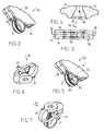
- a brake shoe 10 is slidably mounted on the hanger rope 2, whose structure better from the FIGS. 2 to 4 is apparent.
- the brake shoe 10 consists of four interconnected parts 11, 12 and 13, 14, wherein the parts 11, 12 form a conical channel for the insertion of the Kausche 7.
- the parts 13, 14 are side cover plates.
- the two parts 13, 14 of the brake shoe 10 are provided in the embodiment with nubs 15 which engage in recesses (not shown) of the recess 7 in the retracted braking position of the brake shoe 10.
- the knobs may also be arranged on the thimble 7 and the depressions on the brake shoe 10.
- the hanger rope 2 is clamped between the thimble 7 and the brake shoe 10 and thus firmly connected to the thimble 7.
- FIG. 5 a slightly modified embodiment of the brake shoe 20 is shown.
- the cover plates 13 'and 14' each have an extension 21 with a bore 22. Through the two holes 22, a pin can be pushed through the falling out of the recess 7 is prevented.
- the brake shoe 30 after the FIGS. 6 and 7 is one-piece and has for better handling actuation projections 31st
Landscapes
- Engineering & Computer Science (AREA)
- Mechanical Engineering (AREA)
- Maintenance And Inspection Apparatuses For Elevators (AREA)
- Suspension Of Electric Lines Or Cables (AREA)
- Clamps And Clips (AREA)
Applications Claiming Priority (1)
| Application Number | Priority Date | Filing Date | Title |
|---|---|---|---|
| ATA776/2013A AT514907B1 (de) | 2013-10-09 | 2013-10-09 | Anordnung zur Aufhängung eines Fahrdrahtes |
Publications (2)
| Publication Number | Publication Date |
|---|---|
| EP2860061A2 true EP2860061A2 (fr) | 2015-04-15 |
| EP2860061A3 EP2860061A3 (fr) | 2015-10-28 |
Family
ID=51868929
Family Applications (1)
| Application Number | Title | Priority Date | Filing Date |
|---|---|---|---|
| EP14450045.1A Withdrawn EP2860061A3 (fr) | 2013-10-09 | 2014-10-09 | Système de suspension d'un fil conducteur |
Country Status (2)
| Country | Link |
|---|---|
| EP (1) | EP2860061A3 (fr) |
| AT (1) | AT514907B1 (fr) |
Cited By (4)
| Publication number | Priority date | Publication date | Assignee | Title |
|---|---|---|---|---|
| CN105149946A (zh) * | 2015-10-23 | 2015-12-16 | 江苏天宏自动化科技有限公司 | 一种高铁接触网吊弦自动组装生产线 |
| CN108482188A (zh) * | 2018-05-22 | 2018-09-04 | 中铁电气化局集团有限公司 | 一种压接吊弦压接管和吊弦压接端子的方法 |
| CN112172615A (zh) * | 2020-11-02 | 2021-01-05 | 洛阳火蓝实业有限公司 | 一种新型吊弦 |
| CN115365790A (zh) * | 2022-10-21 | 2022-11-22 | 中铁电气化局集团有限公司 | 一种压装吊弦心形环和钳压管的方法 |
Family Cites Families (6)
| Publication number | Priority date | Publication date | Assignee | Title |
|---|---|---|---|---|
| GB191511172A (en) * | 1915-08-03 | 1916-07-20 | British Insulated And Helsby C | Improvements in Means for Suspending and Adjusting Electricity Overhead Conductors. |
| DE6904332U (de) * | 1969-02-05 | 1969-06-19 | Arthur Flury Ag | Stromschluessige fahrdrahtaufhaengung |
| DE3522543A1 (de) * | 1985-06-24 | 1987-01-02 | Siemens Ag | Haenger fuer kettenfahrleitungen elektrischer bahnen |
| DE20108139U1 (de) * | 2001-05-14 | 2002-09-19 | Diehl Metall Stiftung & Co.KG, 90552 Röthenbach | Klemmvorrichtung |
| CN2883066Y (zh) * | 2006-03-20 | 2007-03-28 | 中铁电气化局集团宝鸡器材厂 | 铰接型可调整体吊弦 |
| AT510367B1 (de) * | 2010-09-14 | 2015-03-15 | Röhl Jahn Dipl Ing Fh | Fahrdrahtklemme für oberleitungskreuzungen |
-
2013
- 2013-10-09 AT ATA776/2013A patent/AT514907B1/de not_active IP Right Cessation
-
2014
- 2014-10-09 EP EP14450045.1A patent/EP2860061A3/fr not_active Withdrawn
Non-Patent Citations (1)
| Title |
|---|
| None |
Cited By (6)
| Publication number | Priority date | Publication date | Assignee | Title |
|---|---|---|---|---|
| CN105149946A (zh) * | 2015-10-23 | 2015-12-16 | 江苏天宏自动化科技有限公司 | 一种高铁接触网吊弦自动组装生产线 |
| CN105149946B (zh) * | 2015-10-23 | 2017-12-26 | 江苏天宏自动化科技有限公司 | 一种高铁接触网吊弦自动组装生产线 |
| CN108482188A (zh) * | 2018-05-22 | 2018-09-04 | 中铁电气化局集团有限公司 | 一种压接吊弦压接管和吊弦压接端子的方法 |
| CN108482188B (zh) * | 2018-05-22 | 2019-03-29 | 中铁电气化局集团有限公司 | 一种压接吊弦压接管和吊弦压接端子的方法 |
| CN112172615A (zh) * | 2020-11-02 | 2021-01-05 | 洛阳火蓝实业有限公司 | 一种新型吊弦 |
| CN115365790A (zh) * | 2022-10-21 | 2022-11-22 | 中铁电气化局集团有限公司 | 一种压装吊弦心形环和钳压管的方法 |
Also Published As
| Publication number | Publication date |
|---|---|
| EP2860061A3 (fr) | 2015-10-28 |
| AT514907B1 (de) | 2015-07-15 |
| AT514907A1 (de) | 2015-04-15 |
Similar Documents
| Publication | Publication Date | Title |
|---|---|---|
| AT514907B1 (de) | Anordnung zur Aufhängung eines Fahrdrahtes | |
| DE1465725B2 (de) | Klemmvorrichtung | |
| DE10393804T5 (de) | Klemme | |
| DE102012007298B4 (de) | Vorrichtung zum höhenverstellbaren Abhängen eines elektrischen Gerätes | |
| DE3522543C2 (fr) | ||
| DE102010028724A1 (de) | Fahrleitungssystem, Verfahren zur Verbindung eines Fahrdrahts mit einem Tragseil sowie Verwendung eines Z-Seils und einer Stoßklemme | |
| DE3038418A1 (de) | Seil- oder kabelklemme | |
| DE102010007581B4 (de) | Energieführungskette | |
| DE1905379C3 (de) | Schraubenlose Klemme | |
| AT516347B1 (de) | Anordnung zur Aufhängung mindestens eines Fahrdrahtes elektrischer Bahnen | |
| DE3220005C1 (de) | Hängerklemme für zwei parallele Tragseile einer Oberleitung elektrischer Bahnen | |
| DE3129973C2 (de) | Selbsttätige Seilklemme mit einem Klemmkeil und Klemmflächen | |
| DE102008058594B4 (de) | Hängerklemme | |
| DE102010012075B3 (de) | Geräteeinbaudose für Leitungsführungskanäle oder Installationskanäle | |
| DE3511900A1 (de) | Seitenhalter fuer oberleitungen elektrischer bahnen | |
| EP0904507B1 (fr) | Support pour conduites | |
| DE704413C (de) | Einstellbare Seilklemme | |
| DE202010008118U1 (de) | Halter sowie Anordnung umfassend einen solchen Seilhalter und ein Trägerprofil | |
| AT15867U1 (de) | Vorrichtung zum Befestigen eines Beschäftigungsmittels für Schweine | |
| DE1515324B2 (de) | Hängerklemme mit Klemmschraube, zur Befestigung am Tragseil einer Kettenwerkfahrleitung elektrischer Bahnen | |
| DE202021104763U1 (de) | Leitungswagen | |
| DE2427523C2 (de) | Hängerklemme für Fahrleitungen elektrischer Bahnen | |
| DE2342830A1 (de) | Haengerklemme | |
| DE2342829C3 (de) | Hängerklemme | |
| DE1073177B (de) | Klemmvorrichtung für die Verbindung des Förderseils mit einer im Schacht angeordneten Tragbühne |
Legal Events
| Date | Code | Title | Description |
|---|---|---|---|
| PUAI | Public reference made under article 153(3) epc to a published international application that has entered the european phase |
Free format text: ORIGINAL CODE: 0009012 |
|
| 17P | Request for examination filed |
Effective date: 20141009 |
|
| AK | Designated contracting states |
Kind code of ref document: A2 Designated state(s): AL AT BE BG CH CY CZ DE DK EE ES FI FR GB GR HR HU IE IS IT LI LT LU LV MC MK MT NL NO PL PT RO RS SE SI SK SM TR |
|
| AX | Request for extension of the european patent |
Extension state: BA ME |
|
| PUAL | Search report despatched |
Free format text: ORIGINAL CODE: 0009013 |
|
| AK | Designated contracting states |
Kind code of ref document: A3 Designated state(s): AL AT BE BG CH CY CZ DE DK EE ES FI FR GB GR HR HU IE IS IT LI LT LU LV MC MK MT NL NO PL PT RO RS SE SI SK SM TR |
|
| AX | Request for extension of the european patent |
Extension state: BA ME |
|
| RIC1 | Information provided on ipc code assigned before grant |
Ipc: B60M 1/225 20060101ALI20150921BHEP Ipc: B60M 1/23 20060101AFI20150921BHEP Ipc: B60M 1/24 20060101ALI20150921BHEP |
|
| R17P | Request for examination filed (corrected) |
Effective date: 20151126 |
|
| RBV | Designated contracting states (corrected) |
Designated state(s): AL AT BE BG CH CY CZ DE DK EE ES FI FR GB GR HR HU IE IS IT LI LT LU LV MC MK MT NL NO PL PT RO RS SE SI SK SM TR |
|
| STAA | Information on the status of an ep patent application or granted ep patent |
Free format text: STATUS: THE APPLICATION IS DEEMED TO BE WITHDRAWN |
|
| 18D | Application deemed to be withdrawn |
Effective date: 20180501 |