EP2860107B1 - Giersteuerung von koaxialem Rotor - Google Patents
Giersteuerung von koaxialem Rotor Download PDFInfo
- Publication number
- EP2860107B1 EP2860107B1 EP14188109.4A EP14188109A EP2860107B1 EP 2860107 B1 EP2860107 B1 EP 2860107B1 EP 14188109 A EP14188109 A EP 14188109A EP 2860107 B1 EP2860107 B1 EP 2860107B1
- Authority
- EP
- European Patent Office
- Prior art keywords
- rotor
- zone
- degrees
- rotation angles
- blade
- Prior art date
- Legal status (The legal status is an assumption and is not a legal conclusion. Google has not performed a legal analysis and makes no representation as to the accuracy of the status listed.)
- Active
Links
Images


Classifications
-
- B—PERFORMING OPERATIONS; TRANSPORTING
- B64—AIRCRAFT; AVIATION; COSMONAUTICS
- B64C—AEROPLANES; HELICOPTERS
- B64C27/00—Rotorcraft; Rotors peculiar thereto
- B64C27/04—Helicopters
- B64C27/08—Helicopters with two or more rotors
- B64C27/10—Helicopters with two or more rotors arranged coaxially
-
- B—PERFORMING OPERATIONS; TRANSPORTING
- B64—AIRCRAFT; AVIATION; COSMONAUTICS
- B64U—UNMANNED AERIAL VEHICLES [UAV]; EQUIPMENT THEREFOR
- B64U30/00—Means for producing lift; Empennages; Arrangements thereof
- B64U30/20—Rotors; Rotor supports
- B64U30/24—Coaxial rotors
-
- B—PERFORMING OPERATIONS; TRANSPORTING
- B64—AIRCRAFT; AVIATION; COSMONAUTICS
- B64C—AEROPLANES; HELICOPTERS
- B64C27/00—Rotorcraft; Rotors peculiar thereto
- B64C27/54—Mechanisms for controlling blade adjustment or movement relative to rotor head, e.g. lag-lead movement
- B64C27/72—Means acting on blades
- B64C2027/7205—Means acting on blades on each blade individually, e.g. individual blade control [IBC]
-
- B—PERFORMING OPERATIONS; TRANSPORTING
- B64—AIRCRAFT; AVIATION; COSMONAUTICS
- B64U—UNMANNED AERIAL VEHICLES [UAV]; EQUIPMENT THEREFOR
- B64U10/00—Type of UAV
- B64U10/10—Rotorcrafts
- B64U10/17—Helicopters
-
- B—PERFORMING OPERATIONS; TRANSPORTING
- B64—AIRCRAFT; AVIATION; COSMONAUTICS
- B64U—UNMANNED AERIAL VEHICLES [UAV]; EQUIPMENT THEREFOR
- B64U2201/00—UAVs characterised by their flight controls
- B64U2201/20—Remote controls
-
- Y—GENERAL TAGGING OF NEW TECHNOLOGICAL DEVELOPMENTS; GENERAL TAGGING OF CROSS-SECTIONAL TECHNOLOGIES SPANNING OVER SEVERAL SECTIONS OF THE IPC; TECHNICAL SUBJECTS COVERED BY FORMER USPC CROSS-REFERENCE ART COLLECTIONS [XRACs] AND DIGESTS
- Y02—TECHNOLOGIES OR APPLICATIONS FOR MITIGATION OR ADAPTATION AGAINST CLIMATE CHANGE
- Y02T—CLIMATE CHANGE MITIGATION TECHNOLOGIES RELATED TO TRANSPORTATION
- Y02T50/00—Aeronautics or air transport
- Y02T50/30—Wing lift efficiency
Definitions
- the subject matter disclosed herein relates to a set of coaxial counter-rotating rotor assemblies in which each individual blade is controlled separately and, in particular, to controlling rotor blades of the rotor assemblies to receive different rotor pitch angle control commands in different rotor azimuth angle.
- Helicopters using coaxial counter-rotating rotors use differential collective between the rotors to provide yaw control at low and moderate speeds.
- the differential collective makes the blade collective angle of one rotor go up and the blade collective angle of the counter-rotating rotor blade go down. This provides increased torque for one rotor and decreased torque for the other rotor. Since the rotors rotate in opposite direction the net yawing moment felt by fuselage add up in the same direction.
- Rotor blades of rotary-wing aircraft typically receive a down-flow of air coming to the rotor from above.
- the differential collective provides a yawing moment in an expected, and correct, direction.
- the torque, and therefore yawing moment, created by increasing blade collective may be in the opposite direction, and control of the aircraft is degraded.
- This is called autorotation state of the rotor.
- the rotor is producing lift but requires no power applied to the rotor because up-flow through the rotor produces torque in the direction to propel the rotor and balances the torque required to rotate the rotor.
- the down-flow (in-flow) of the rotor is reduced and even changes to up-flow on the forward part of the rotor and the down-flow is increased on the aft part of the rotor.
- yaw control provided by differential collective in co-axial counter rotating rotors degrades significantly at forward speeds and descending flights. Additional means of yaw control arc provided in such designs. These include large rudders located at the back end of the helicopters. Because rudder effectiveness is proportional to the square of helicopter speed, large rudders are necessary to be useful at lower speeds. In addition, thrusters may be used. Both these designs increase cost, weight and complexity of the aircraft.
- EP 2 476 614 A2 describes a method of counteracting a rotor moment of one or more rotors of a concentric dual-rotor helicopter which includes sensing angular velocity and angular acceleration of a helicopter during a flight maneuver. The angular velocity and angular acceleration are compared to a set of control parameters and one or more control servos change the cyclic pitch of the one or more rotors to counteract the rotor moment.
- a control system for counteracting a rotor moment of one or more rotors of a concentric dual-rotor helicopter includes one or more sensors configured to sense angular velocity and angular acceleration of a helicopter during a flight maneuver.
- a computer is operably connected to the one or more sensors and configured to compare sensor data to a set of control parameters.
- a plurality of control servos change the cyclic pitch of the one or more rotors to counteract the rotor moment.
- US 2008/203222 A1 discloses a yaw control system and a method of controlling yaw for an aircraft.
- the yaw control system includes a first wing set and a second wing set which are rotatable in opposite directions.
- Each of the wing sets includes at least two wings each including a pivotable flap forming a trailing edge of its respective wing.
- a flap control assembly controls the pivotable flaps of the first wing set and of the second wing set such that when the pivotable flaps of the first wing set are pivoted in a first direction by a first set angle, the pivotable flaps of the second wing set are simultaneously pivoted by a second set angle in an opposite direction, thereby providing yaw control for the aircraft.
- a counter rotating helicopter blade movement mechanism has a cyclical plane single stage having shaft combinations on the moving platform. There is an outer fixed plane and inner rotating plane with holes and an inner sliding rotule. There is a lower fixed plane commanding connection of the rotating plane with a fixed command point engaging the moving platform.
- GB 910 678 A discloses a helicopter having two, coaxial, contrarotative lifting or/and sustaining rotors, collective and cyclic pitch control mechanism including two swash-plate assemblies, each comprising a non-rotative member mechanically connected to the pilot's controls and a rotative member having no mechanical interconnection with the rotative member of the other swash-plate assembly, such assemblies being independently displaceable axially of the rotors for collective pitch and yawing control and each tiltable in any azimuth for cyclic pitch control.
- the swash-plate assembly controlling the lower rotor being above that controlling the upper rotor and its rotative member is connected with the pitch adjusting arms secured to the blades of the lower rotor by conventional linkages and the rotative member of the swash-plate assembly controlling the upper rotor being operatively connected with the similar pitch-adjusting arms of the blades of the upper rotor by a mechanism which includes separate coaxially nested push-pull members coaxially slidable within the hollow contrarotative shafts which respectively drive or constitute the axles of the upper and lower rotors, an each such pushpull member is operatively connected to the pitch-adjusting arm of one blade of the upper rotor.
- a method for controlling rotor blades of a co-axial rotor assembly of an aircraft including a first rotor co-axial with a second rotor includes identifying a first zone of rotor rotation angles of the co-axial rotor assembly by using sensors for determining portions of the rotors subjected to up-flow according to claim 1.
- the first zone defines a range of rotor rotation angles corresponding to an up-flow of air to the coaxial rotor assembly, and the remainder of the rotor rotation angles other than the first zone of rotation angles is defined as a second zone.
- the method includes receiving a yaw command to adjust a yaw moment of the aircraft and applying a different rotor blade angle change to rotor blades in the first zone than a rotor blade angle change applied to rotor blades in the second zone to adjust the yaw moment of the aircraft according to the yaw command.
- Particular embodiments may include any of the following optional features, alone or in combination:
- the change in rotor blade angle applied to rotor blades in the second zone of the first rotor may be opposite the change in rotor blade angle applied to rotor blades in the second zone of the second rotor.
- the range of angles corresponding to the first zone may correspond to an up-flow of air to the first rotor, and the method further may comprise: Identifying a third zone of rotation angles of the second rotor, the third zone defining a range of rotor rotation angles corresponding to an up-flow of air to the second rotor, and the third zone having a size different from the first zone, and the remainder of the rotor rotation angles of the second rotor other than the third zone of rotation angles being defined as a fourth zone; applying a different rotor blade angle change to rotor blades in the third zone than a rotor blade angle change applied to rotor blades in the fourth zone to adjust the yaw moment of the aircraft according to the yaw command.
- the method further may comprise: Individually and separately controlling the blade pitch angle of each rotor blade of the co-axial rotor assembly.
- the method further may comprise: Adjusting the rotor blade angle of each rotor blade within the first zone and the second zone according to an azimuthal position of the each rotor blade within the first zone and the second zone, respectively.
- the first zone may include a range of rotation angles within a range between, and including, ninety (90) degrees and two-hundred seventy (270) degrees, and passing through one-hundred eighty (180) degrees, where one hundred eighty (180) degrees is defined by a front end of a fuselage of the aircraft.
- the change in rotor blade angle of the rotor blades in the first zone may be around zero (0) degrees.
- the first zone may include a range of rotation angles within a range between, and including, ninety (90) degrees and two-hundred seventy (270) degrees, and passing through one-hundred eighty (180) degrees, where one hundred eighty (180) degrees is defined by a front end of a fuselage of the aircraft, and the change in rotor blade angle of the rotor blades in the first zone may be around zero (0) degrees.
- the rotor assembly includes a first rotor including a plurality of rotor blades configured to rotate around a shaft, a second rotor being co-axial with the first rotor and rotating in a direction opposite the first rotor and a rotor-blade controller.
- the rotor-blade controller is configured to identify a first zone of rotor rotation angles of the co-axial rotor assembly by using sensors for determining portions of the rotors subjected to up-flow, the first zone defining a range of rotor rotation angles corresponding to predominantly an up-flow of air to the coaxial rotor assembly, and the remainder of the rotor rotation angles other than the first zone of rotation angles being defined as a second zone.
- the rotor-blade controller is configured to receive a yaw command to adjust a yaw moment of the aircraft, and the rotor-blade controller is configured to apply a different rotor blade angle change to rotor blades in the first zone than a rotor blade angle change applied to rotor blades in the second zone to adjust the yaw moment of the aircraft according to the yaw command.
- Particular embodiments may include any of the following optional features, alone or in combination:
- the change in rotor blade angle applied to rotor blades in the second zone of the first rotor may be opposite the change in rotor blade angle applied to rotor blades in the second zone of the second rotor.
- the range of angles corresponding to the first zone may correspond to an up-flow of air to the first rotor; the rotor-blade controller further may be configured to identify a third zone of rotation angles of the second rotor, the third zone defining a range of rotor rotation angles corresponding to an up-flow of air to the second rotor, the third zone having a size different from the first zone, and the remainder of the rotor rotation angles of the second rotor other than the third zone of rotation angles being defined as a fourth zone, and the rotor-blade controller further may be configured to apply a different rotor blade angle change to rotor blades in the third zone than a rotor blade angle change applied to rotor blades in the fourth zone to adjust the yaw moment of the aircraft according to the yaw command.
- the rotor-blade controller may be configured to individually and separately control the blade pitch angle of each rotor blade of the co-axial rotor assembly.
- the first zone may include a range of rotation angles within a range between, and including, ninety (90) degrees and two-hundred seventy (270) degrees, and passing through one-hundred eighty (180) degrees, where one hundred eighty (180) degrees is defined by a front end of a fuselage of the aircraft.
- the change in rotor blade angle of the rotor blades in the first zone may be around zero (0) degrees.
- the first zone may include a range of rotation angles within a range between, and including, ninety (90) degrees and two-hundred seventy (270) degrees, and passing through one-hundred eighty (180) degrees, where one hundred eighty (180) degrees is defined by a front end of a fuselage of the aircraft, and the change in rotor blade angle of the rotor blades in the first zone may be around zero (0) degrees.
- Co-axial aircraft rotor systems and in particular, counter-rotating systems, suffer from loss of control at certain speeds and travel directions, such as when descending at medium speeds.
- Embodiments of the invention relate to controlling rotor blades of a rotor system to improve yaw control of an aircraft.
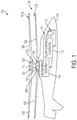
- FIG. 1 illustrates a co-axial rotor-based system 100 according to an embodiment of the invention.
- the system 100 includes an aircraft, such as a helicopter or other rotary-wing aircraft.
- the system 100 includes a fuselage 110 and a compound rotor assembly 120.
- the compound rotor assembly 120 rotates to lift and maintain the system 100 airborne.
- the compound rotor assembly 120 includes first and second rotor assemblies 121a and 121b that are co-axial and rotate in opposite direction with each other.
- the fuselage 110 houses a pilot 111, physical flight controls 112, a flight control computer 113 and a rotor drive assembly 114.
- the pilot 111 physically manipulates the physical flight controls 112, which may include a stick, lever, wheel, rudder pedals, side arm control arrangements or any other type of physical control, to generate command signals or values for longitudinal, lateral, yaw and collective movement of the system 100.
- the system 100 may be controlled by aircraft and rotor controls mechanically, with direct mechanical connections, or by a flight control computer 130, or by any combination of physical controls and computer controls.
- a flight control computer 130 may interpret positions of the physical flight controls 112 to generate the commands, or the physical flight controls 112 may include sensors or other mechanisms to translate physical positions and movements into electrical signals that are transmitted to the flight control computer 113.
- the flight control computer 113 includes memory, one or more processors, logic and other circuitry to generate, process, and/or transmit the command signals or values.
- the command signals may include a lateral command, a longitudinal command, a yaw command and a collective command to control lateral movement of the system 100, longitudinal movement of the system 100, a rotation of the system 100 and total thrust of the system 100.
- the longitudinal command corresponds to a forward and backward motion of the fuselage 110, and in particular to the lowering and raising of the nose and the tail;
- the lateral command corresponds to a side-to-side motion of the fuselage 110, and in particular rolling the aircraft left or right;
- yaw corresponds to rotation of the fuselage 110 nose to the right or left to change a direction of the nose of the fuselage 110;
- the collective command corresponds to increasing or decreasing thrust of the fuselage 110 resulting the raising or lowering of the entire fuselage 110 simultaneously.
- the flight control computer 113 may store flight control programs and other electronics that may take into account various environmental conditions and characteristics of the system 100 to generate the command signals.
- the command signals are transmitted to the rotor drive assembly 114.
- the rotor drive assembly 114 may include, for example, one or more motors or engines to drive one or more gears and shafts.
- the gears and shafts in turn, drive the compound rotor assembly 120.
- the rotor drive assembly 114 drives the first rotor assembly 121a in a first direction and the second rotor assembly 121b in an opposite direction.
- the first rotor assembly 121a includes rotor blades 123 and 124, servos 127 and 128 to control the position of the rotor blades 123 and 124 and a servo-control computer 131 to calculate individual rotor control signals for each rotor blade 123 and 124 and to transmit the individual rotor control signals to the respective servos 127 and 128.
- the flight control computer 113 transmits to the servo-control computer 131 command signals based on the position of the controls 112.
- the second rotor assembly 121b includes rotor blades 125 and 126, servos 129 and 130 to control the position of the rotor blades 125 and 126 and a servo-control computer 132 to calculate individual rotor control signals for each rotor blade 125 and 126 and to transmit the individual rotor control signals to the respective servos 129 and 130.
- the flight control computer 113 transmits to the servo-control computer 132 command signals based on the position of the controls 112.
- the servo-control computer 132 receives the command signals from the flight control computer 113 and calculates the appropriate individual signals for each separate servo 129 and 130.
- the separate control signals generated for the separate servos 127, 128, 129 and 130 may be based on each of the lateral, longitudinal, yaw and collective command signals.
- embodiments of the invention are not limited to the configuration illustrated in FIG. 1 .
- the flight control computer 113 could generate the individual rotor blade control signals.
- the servo-control computers 131 and 132 may be the same computer.
- the servo-control computers 131 and 132 may be located in the fuselage 110.
- embodiments of the invention encompass any unitary or distributed computing system that receives pilot controls and outputs individual and different control signals to different rotor blades of a rotor assembly based on the same command signals generated from the pilot controls.
- FIG. 1 illustrates controls 112 that are physically manipulated by a pilot 111
- embodiments of the invention are not limited to a human pilot 111 or a pilot 111 located in the fuselage 110.
- the system 100 may be controlled by a computer executing a computer program, or the system 100 may be controlled remotely by a human or computer controller that is not located in the fuselage 110.
- a computer may replace the physical controls 112 to generate the latitude, longitude and collective commands.
- each rotor blade 123, 124, 125 and 126 of the rotor assemblies 121a and 121b is controlled by a separate servo 127, 128, 129 and 130.
- the system 100 does not include a swashplate and does not use a swashplate to control the position of the rotor blades 123, 124, 125 or 126.
- each rotor blade 123, 124, 125 and 126 is controlled by a separate servo 127, 128, 129 and 120 that receives a separate rotor blade control signal.
- FIG. 2 illustrates a reference for determining the azimuthal position of the rotor assembly 121b of FIG. 1 , including the rotor blades 125, 126, 145 and 146.
- a first rotor blade 125 is controlled by a first servo 129
- a second rotor blade 126 is controlled by a second servo 130
- a third rotor blade 145 is controlled by a third servo 133
- a fourth rotor blade 146 is controlled by a fourth servo 134.
- the rear of the fuselage 110 is defined as a zero degree position, and the angular positions increase in a counter-clockwise direction, looking down at system 100 from above.
- the azimuthal position of the first rotor blade 125 is zero (0) degrees; when the first rotor blade 125 is at an angle ninety (90) degrees counter-clockwise from the rear of the fuselage 110, the azimuthal position of the first rotor blade 125 is ninety (90) degrees, etc.
- the rotation area of the first and second rotors 121a and 121b is divided into multiple zones, and different rotor-blade control signals are generated to control the rotor blades in each zone.
- FIGS. 3A and 3B illustrate examples of dividing the rotation area of a rotor into zones according to an embodiment of the invention.
- a rotation area 300 of a rotor such as the first or second rotor 121a or 121b is three hundred and sixty (360) degrees.
- a first zone 301 is defined as the forward portion of the rotation area 300, or the portion 301 between the angles of two hundred and seventy (270) degrees and ninety (90) degrees, passing through one hundred and eighty (180) degrees.
- the second zone 302 is defined as the aft portion of the rotation area 300, or the portion 302 between the angles of two hundred and seventy (270) degrees and ninety (90) degrees, passing through zero (0) degrees.
- the first and second zones 301 and 302 are not limited to the regions in FIG. 3A , but may correspond to any desired regions.
- FIG. 3B illustrates the first zone 301 as extending between the angles of two hundred and ninety (290) degrees and seventy (70) degrees, passing through one hundred and eighty (180) degrees.
- the second zone 302 is defined as the aft portion of the rotation area 300, or the portion 302 between the angles of two hundred and ninety (290) degrees and seventy (70) degrees, passing through zero (0) degrees.
- FIGS. 3A and 3B illustrate only two examples of dividing a rotation area of a rotor into different rotor-command zones, embodiments of the invention are not limited to the illustrated examples.
- the first region includes the one hundred eighty (180) degree rotation angle and the second region 302 includes the zero (0) degree rotation angle.
- each of the first rotor 121a and the second rotor 121b may be divided into zones corresponding to an up-flow portion and a down-flow portion.
- the zones of each of the rotors may have the same angular region or may include different angular regions.
- the rotor blades of the rotors 121a and 121b may have opposing pitch angle changess in each region.
- the rotor blades in the forward region of the first rotor 121a may have a pitch angle change that is opposite a pitch angle change of the rotor blades in the forward region of the second rotor 121b (e.g. five (5) degrees and negative five (-5) degrees).
- the rotor blades in the aft region of the first rotor 121a may have a pitch angle change that is opposite a pitch angle change of the rotor blades in the aft region of the second rotor 121b.
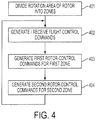
- FIG. 4 is a block diagram of a method of controlling rotor blades according to an embodiment of the invention. One implementation of the invention is described with respect to FIGS. 1 , 2 , 3 and 4 .
- the rotation area of the rotors 121a and 121b is divided into multiple zones, such as zones 301 and 302 of FIGS. 3A and 3B .
- the different zones correspond to regions which receive different rotor blade control commands.
- the zones correspond to different air-flow directions. For example, air may flow through the region 301 in a direction from below the rotors 121a and 121b (i.e. up-flow), and air may flow through the region 302 from in a direction from above the rotors 121a and 121b (i.e., down-flow).
- the airflow will increase as aircraft airspeed and descent rate are increased.
- a range of rotation angles is identified corresponding regions of the rotors that are subjected to, or are likely to be subjected to, an up-flow of air to the rotors.
- the range of rotation angles corresponding to the predominantly up-flow of air is described as being a first zone, such as the first zone 301 of FIGS. 3A and 3B .
- first zone 301 it may be determined that the rotor 121b is subjected to an air flow that is predominantly an up-flow of air in one angular region (first zone 301).
- first zone 302 it may be determined that the rotor 121b is subjected to an air flow that is predominantly a down flow of air in another angular region (second zone 302).
- Subjecting the rotor 121b to predominantly an up-flow of air may cause the rotor-based system 100 to decrease the torque of the rotor when the blade angle is increased. This may cause a yawing moment in the system 100 in the opposite direction from the direction that is conventionally expected by an increase of the rotor blade angle and may cause the system 100 to turn incorrectly, or perform an incorrect yaw adjustment. Therefore, identifying the portion of the rotor 121b that is subjected to the up-flow allows for improved yaw control by not applying any rotor blade angle yaw command in this region. In some cases even a blade angle in reverse direction can be applied for yaw control improvement.
- the first zone, or the range of rotation angles that is determined to be subjected to the up-flow of air through the rotor is the forward portion of the rotor-based system 100, or the portion between the angles of two hundred and seventy (270) degrees and ninety (90) degrees, passing through one hundred and eighty (180) degrees. In one embodiment, this range of angles is determined based on testing or other empirical analysis prior to flight of the rotor-based system 100.
- the invention uses sensors of the rotor-based system 100 to determine the portions of the rotor 121b subjected to the up-flow during operation of the rotor-based system 100, or while the rotor-based system 100 is in flight.
- the entire portion of the rotor 121b between, and including, two hundred and seventy (270) degrees and ninety (90) degrees, passing through one hundred and eighty (180) degrees is treated as a predetermined range of rotation angles that is subjected to special control.
- a sub-set of angles within the range of two hundred and seventy (270) degrees and ninety (90) degrees, passing through one hundred and eighty (180) degrees is determined to be subjected to up-flow. For example, it may be determined that the portion of the rotor 121b between two hundred and fifty-five (255) degrees and one hundred and five (105) degrees, and including one hundred eighty (180) degrees, is subjected to the up-flow. In another example, it may be determined that a portion of the rotor 121b between two hundred and forty (240) degrees and one hundred and twenty (120) degrees, and including one hundred eighty (180) degrees, is subjected to the up-flow of air.
- the range of angles in which it is determined that the rotor 121b is subjected to an up-flow of air may be greater than one-hundred eighty (180) degrees. For example, it may be determined that the portion of the rotor 121b between two hundred and eighty-five (285) degrees and seventy-five (75) degrees, and including one hundred eighty (180) degrees, is subjected to the up-flow. In another example, it may be determined that a portion of the rotor 121b between three-hundred (300) degrees and sixty (60) degrees, and including one hundred eighty (180) degrees, is subjected to the up-flow.
- the portion of the rotation area that is not included in the first zone constitutes a second zone, such as the second zone 302 of FIG. 3 .
- the first zone corresponds to a range of rotation angles in which the rotors 121a and 121b are subjected to predominantly an up-flow of air (air coming to the rotor from below)
- the second zone corresponds to a range of rotation angles in which the rotors 121a and 121b are subjected to predominantly down-flow of air (air coming to the rotor from above).
- embodiments of the invention encompass dividing the rotation area of the rotors 121a and 121b into zones for providing different rotor control commands for any reason.
- flight control commands are received by a rotor-control computer, such as the rotor-control computers 131 and 132 of FIG. 1 .
- the flight control commands are generated based on pilot manipulation of physical controls, and in another embodiment, the flight control commands are generated based on a remote control or based on execution of a flight program by an auto-pilot.
- the flight control commands may include yaw commands to position the rotor-based system 100 to have a particular yaw.
- the yaw commands may include a target yaw value.
- the target yaw value may correspond to a yaw rotation of five (5) degrees to the right from a present heading of the fuselage 110.
- different target yaw values are generated by the pilot of flight-control computer and received by the rotor-control computer.
- a set of first rotor control commands is generated to control the yawing moment of system 100.
- the yawing moment is controlled by controlling the rotor blade angles for individual rotor blades of a rotor assembly.
- the rotor blade angle changes are controlled to be different in a first zone, corresponding to a first angular region in which a flow of air to the rotor blades is predominantly an up-flow of air and a second zone corresponding to a second angular region complementary to the first angular region in which a flow of air to the rotor blades is predominantly a down-flow of air.
- the rotor blade angle change in the first region, in which the flow of air to the rotor blades is predominantly an up-flow of air, the rotor blade angle change is controlled to be zero (0). In another embodiment, the rotor blade angle change is controlled to be closer to zero (0) than in the second region. In yet another embodiment, the rotor blade angle change is controlled to be negative with respect to the rotor blade angle in the second zone.
- the rotor blade angle changes of the rotor blades in the second region are controlled to be different than in the first region.
- the rotor blade angle change is controlled according to the yawing moment command to position the aircraft in the manner indicated by the yawing moment command. For example, if the yawing moment command provided by a pilot or flight control computer indicates that the aircraft should turn, the rotor blades in the first zone are adjusted by an angle around zero, and the rotor blades in the second zone are adjusted by an angle that corresponds to the turn indicated by the yawing moment command.
- a yaw command is received by a rotor blade controller to adjust the yaw of the aircraft.
- the rotor blade controller may determine that adjusting the pitch of the rotor blades by six (6) degrees would turn the aircraft to the correct yaw moment.
- the rotor blades in the first zone corresponding to the region in which an up-flow is provided to the rotor blades, may be controlled to remain unchanged (i.e. at a pitch of five (5) degrees to maintain the lift of the aircraft).
- the rotor blades of a second co-axial and counter-rotating rotor may be controlled such that the rotor blades of the co-axial rotor in the first zone remain unchanged in response to the yaw command, and the rotor blades in the second zone are adjusted at a magnitude opposite the rotor blades of the first rotor (i.e. adjusted by minus six (-6) degrees) in response to the yaw command.
- embodiments of the invention encompass rotor blades in the first zone being adjusted in a same direction, but at a lesser magnitude, than rotor blades in the second zone; rotor blades in the first zone being adjusted in an opposite direction than in the first zone; and rotor blades in the first zone being maintained at a constant pitch in response to any yaw command.
- the change in rotor blade angle command of one or both of the first and second rotors located within the same zone may be opposite in sign and may have the same magnitude (but with an opposite sign) or a different absolute magnitude.
- the rotor blades in the first zone are controlled to remain at a constant pitch regardless of the received yaw command.
- the rotor blades angles are changed in the second zone and are opposite in sign between first and second rotor, and are controlled to change according to the different yaw commands to turn the rotor-based system 100.
- the first rotor-control commands may include rotor-control commands for the rotor blades of the first rotor 121a in the first zone and rotor blades of the second rotor 121b in the first zone.
- the rotor-control commands for each of the first and second rotors 121a and 121b in the first zone is the same.
- the rotor blades in the first zone of the rotation areas of the first and second rotors 121a and 121b may all be controlled to have a change in the rotor pitch angle of around zero (0) degrees, regardless of the flight control commands received in block 402.
- each rotor blade of the first and second rotors 121a and 121b is individually controlled, such that each rotor blade within a predetermined range of rotation angles is arranged at a first pitch angle and each rotor blade outside the predetermined range of rotation angles is arranged at a second pitch angle.
- the first pitch angle may stay substantially the same for every received yaw command, and the second pitch angle may change to correspond to every received yaw command to control the yaw of the aircraft.
Landscapes
- Engineering & Computer Science (AREA)
- Mechanical Engineering (AREA)
- Aviation & Aerospace Engineering (AREA)
- Structures Of Non-Positive Displacement Pumps (AREA)
- Aerodynamic Tests, Hydrodynamic Tests, Wind Tunnels, And Water Tanks (AREA)
Claims (14)
- Verfahren zur Steuerung von Rotorblättern (123, 124,1 125, 126) einer koaxialen gegenläufigen Rotoranordnung (120) eines Luftfahrzeugs, das einen ersten Rotor (121a) koaxial zu einem zweiten Rotor (121b) beinhaltet, umfassend:Identifizieren einer ersten Zone (301) von Rotordrehwinkeln der koaxialen gegenläufigen Rotoranordnung (120), wobei die erste Zone (301) einen Bereich von Rotordrehwinkeln definiert, der einer Aufwärtsströmung von Luft zu der koaxialen Rotoranordnung entspricht, wobei die Luft, aufgrund der Vorwärtsgeschwindigkeit und/oder des Steigens des Luftfahrzeugs, durch die erste Zone (301) in eine Richtung von unterhalb der Rotoren (121a, 121b) strömt, und der Rest der Rotordrehwinkel, anders als die erste Zone (301) von Drehwinkeln, als eine zweite Zone (302) definiert ist.Empfangen eines Gierbefehls, um ein Giermoment des Luftfahrzeugs anzupassen; undAnwenden einer anderen Rotorblattwinkeländerung bei den Rotorblättern in der ersten Zone (301) als bei einer Rotorblattwinkeländerung bei den Rotorblättern in der zweiten Zone (302) angewendet wird, um das Giermoment des Luftfahrzeugs entsprechend dem Gierbefehl anzupassen.
- Verfahren nach Anspruch 1, wobei die Änderung des Rotorblattwinkels, die bei Rotorblättern (123, 124) in der zweiten Zone (302) des ersten Rotors (121a) angewendet wird, die gegensätzliche Änderung des Rotorblattwinkels ist, die bei Rotorblättern (125, 126) in der zweiten Zone (302) des zweiten Rotors (121b) angewendet wird.
- Verfahren nach Anspruch 1 oder 2, wobei der Bereich von Winkeln, der der ersten Zone (301) entspricht, einer Aufwärtsströmung von Luft zu dem ersten Rotor (121a) entspricht, wobei des Verfahren ferner umfasst:Identifizieren einer dritten Zone von Drehwinkeln des zweiten Rotors (121b), wobei die dritte Zone einen Bereich von Rotordrehwinkeln definiert, der einer Aufwärtsströmung von Luft zu dem zweiten Rotor (121b) entspricht, und wobei die dritte Zone eine andere Größe als die erste Zone (301) aufweist, und der Rest der Rotordrehwinkel des zweiten Rotors (121b), anders als die dritte Zone von Drehwinkeln, als eine vierte Zone definiert ist;Anwenden einer anderen Rotorblattwinkeländerung bei den Rotorblättern (125, 126) in der dritten Zone als bei einer Rotorblattwinkeländerung bei den Rotorblättern (125, 126) in der vierten Zone angewendet wird, um das Giermoment des Luftfahrzeugs entsprechend dem Gierbefehl anzupassen.
- Verfahren nach einem der Ansprüche 1 bis 3, ferner umfassend:individuelles und separates Steuern des Blattverstellwinkels jedes Rotorblatts (123, 124, 125, 126) der koaxialen Rotoranordnung (120).
- Verfahren nach einem der Ansprüche 1 bis 4, ferner umfassend:Anpassen des Rotorblattwinkels jedes Rotorblatts (123, 124, 125, 126) innerhalb der ersten Zone (301) und der zweiten Zone (302) gemäß einer jeweils azimutalen Position jedes Rotorblatts innerhalb der ersten Zone (301) und der zweiten Zone (302).
- Verfahren nach einem der Ansprüche 1 bis 5, wobei die erste Zone (301) einen Bereich von Drehwinkeln beinhaltet, der Bereich zwischen einschließlich 90 Grad (90) und zweihundertsiebzig Grad (270) liegt, und durch einhundertachtzig Grad (180) verläuft, wobei einhundertachtzig Grad (180) durch ein vorderes Ende eines Rumpfs des Luftfahrzeugs definiert werden.
- Verfahren nach einem der Ansprüche 1 bis 6, wobei die Änderung des Rotorblattwinkels der Rotorblätter in der ersten Zone (301) etwa null Grad (0) beträgt.
- Koaxiale Rotoranaordnung (120) eines Luftfahrzeugs, umfassend:einen ersten Rotor (121a), der eine Vielzahl an Rotorblättern (123, 124) beinhaltet, die dazu konfiguriert sind, um eine Welle zu rotieren;einen zweiten Rotor (121b) koaxial zu dem ersten Rotor (121a) und in einer gegensätzlichen Richtung zu dem ersten Rotor (121a) rotierend; undeine Rotorblattsteuerungdadurch gekennzeichnet, dass die Rotorblattsteuerung dazu konfiguriert ist, eine erste Zone (301) von Rotordrehwinkeln der koaxialen Rotoranordnung zu identifizieren (120), wobei die erste Zone (301) einen Bereich von Rotordrehwinkeln definiert (120), der einer Aufwärtsströmung von Luft zu der koaxialen Rotoranordnung entspricht, wobei die Luft, aufgrund der Vorwärtsgeschwindigkeit und/oder des Steigens des Luftfahrzeugs, durch die erste Region (301) in eine Richtung von unterhalb der Rotoren (121a, 121b) strömt, und der Rest der Rotordrehwinkel, anders als die erste Zone (301) an Drehwinkeln, als eine zweite Zone (302) definiert ist, die Rotorblattsteuerung dazu konfiguriert ist, einen Gierbefehl zu empfangen, um ein Giermoment des Luftfahrzeugs anzupassen, und dazu konfiguriert ist, eine andere Rotorblattwinkeländerung bei den Rotorblättern (123, 124, 125, 126) in der ersten Zone (301) anzuwenden als eine Rotorblattwinkeländerung, die bei den Rotorblättern (123, 124, 125, 126) in der zweiten Zone (302) angewendet wird, um das Giermoment des Luftfahrzeugs entsprechend dem Gierbefehl anzupassen.
- Koaxiale Rotoranordnung (120) nach Anspruch 8, wobei die Änderung des Rotorblattwinkels, die bei Rotorblättern (123, 124, 125, 126) in der zweiten Zone (302) des ersten Rotors (121a) angewendet wird, die gegensätzliche Änderung des Rotorblattwinkels ist, die bei Rotorblättern (123, 124, 125, 126) in der zweiten Zone (302) des zweiten Rotors (121b) angewendet wird.
- Koaxiale Rotoranordnung (120) nach Anspruch 8 oder 9, wobei der Bereich von Winkeln, die der ersten Zone (301) entspricht, einer Aufwärtsströmung von Luft zu dem ersten Rotor (121a) entspricht, und die Rotorblattsteuerung ferner dazu konfiguriert ist:eine dritte Zone von Drehwinkeln des zweiten Rotors (121b) zu identifizieren, wobei die dritte Zone einen Bereich von Rotordrehwinkeln definiert, der einer Aufwärtsströmung von Luft zu dem zweiten Rotor (121b) entspricht, und wobei die dritte Zone eine andere Größe als die erste Zone (301) aufweist, und der Rest der Rotordrehwinkel des zweiten Rotors (121b), anders als die dritte Zone von Drehwinkeln, als eine vierte Zone definiert ist;eine andere Rotorblattwinkeländerung bei den Rotorblättern (125, 126) in der dritten Zone anzuwenden als eine Rotorblattwinkeländerung, die bei den Rotorblättern (125, 126) in der vierten Zone angewendet wird, um das Giermoment des Luftfahrzeugs entsprechend dem Gierbefehl anzupassen.
- Koaxiale Rotoranordnung (120) nach einem der Ansprüche 8 bis 10, wobei die Rotorblattsteuerung ferner dazu konfiguriert ist:den Blattverstellwinkel jedes Rotorblatts (123, 124, 125, 126) der koaxialen Rotoranordnung (120) individuell und separat zu steuern.
- Koaxiale Rotoranordnung (120) nach einem der Ansprüche 8 bis 11, wobei die Rotorblattsteuerung ferner dazu konfiguriert ist:den Rotorblattwinkel jedes Rotorblatts (123, 124, 125, 126) innerhalb der ersten Zone (301) und der zweiten Zone (302) gemäß einer jeweils azimutalen Position jedes Rotorblatts innerhalb der ersten Zone (301) und der zweiten Zone (302) anzupassen.
- Koaxiale Rotoranordnung (120) nach einem der Ansprüche 8 bis 12, wobei die erste Zone (301) einen Bereich von Drehwinkeln beinhaltet, der Bereich zwischen einschließlich 90 Grad (90) und zweihundertsiebzig Grad (270) liegt, und durch einhundertachtzig Grad (180) verläuft, wobei einhundertachtzig Grad (180) durch ein vorderes Ende eines Rumpfs des Luftfahrzeugs definiert werden.
- Koaxiale Rotoranordnung (120) nach einem der Ansprüche 8 bis 13, wobei die Änderung des Rotorblattwinkels der Rotorblätter in der ersten Zone (301) etwa null Grad (0) beträgt.
Applications Claiming Priority (1)
| Application Number | Priority Date | Filing Date | Title |
|---|---|---|---|
| US14/049,091 US9452829B2 (en) | 2013-10-08 | 2013-10-08 | Yaw control of co-axial rotor |
Publications (2)
| Publication Number | Publication Date |
|---|---|
| EP2860107A1 EP2860107A1 (de) | 2015-04-15 |
| EP2860107B1 true EP2860107B1 (de) | 2018-12-12 |
Family
ID=51726364
Family Applications (1)
| Application Number | Title | Priority Date | Filing Date |
|---|---|---|---|
| EP14188109.4A Active EP2860107B1 (de) | 2013-10-08 | 2014-10-08 | Giersteuerung von koaxialem Rotor |
Country Status (2)
| Country | Link |
|---|---|
| US (1) | US9452829B2 (de) |
| EP (1) | EP2860107B1 (de) |
Families Citing this family (4)
| Publication number | Priority date | Publication date | Assignee | Title |
|---|---|---|---|---|
| US10611472B2 (en) * | 2013-10-15 | 2020-04-07 | Sikorsky Aircraft Corporation | Coaxial rotor yaw control |
| JP7735200B2 (ja) * | 2022-02-22 | 2025-09-08 | 本田技研工業株式会社 | 姿勢制御装置 |
| CN116305827A (zh) * | 2023-02-16 | 2023-06-23 | 北方工业大学 | 一种融合气动原理的高速飞行器十字舵效估算方法 |
| US20250187720A1 (en) * | 2023-12-08 | 2025-06-12 | Joby Aero, Inc. | System and Method for Yaw Moment Control |
Family Cites Families (16)
| Publication number | Priority date | Publication date | Assignee | Title |
|---|---|---|---|---|
| GB910678A (en) | 1958-07-25 | 1962-11-14 | Jacob Samuel Shapiro | Improvements in or relating to flying control systems of rotary wing aircraft with coaxial contrarotative rotors |
| US3572616A (en) | 1969-09-18 | 1971-03-30 | United Aircraft Corp | Pitch control mechanism for bladed rotor |
| US4195966A (en) | 1978-07-03 | 1980-04-01 | Cornelius George W | Pitch control system for helicopter rotor blades |
| US4720059A (en) | 1986-12-31 | 1988-01-19 | Stearns Jr Hoyt A | High speed helicopter |
| US5152478A (en) | 1990-05-18 | 1992-10-06 | United Technologies Corporation | Unmanned flight vehicle including counter rotating rotors positioned within a toroidal shroud and operable to provide all required vehicle flight controls |
| FR2804403A1 (fr) | 2000-01-28 | 2001-08-03 | Jean Francois Gonzalez | Plateau cyclique avec commande de mouvement de lacet pour un helicoptere birotor contra-rotatif coaxial |
| US6460802B1 (en) * | 2000-09-13 | 2002-10-08 | Airscooter Corporation | Helicopter propulsion and control system |
| US6886777B2 (en) * | 2001-02-14 | 2005-05-03 | Airscooter Corporation | Coaxial helicopter |
| US7604198B2 (en) | 2003-09-25 | 2009-10-20 | Petersen Bruce L | Rotorcraft having coaxial counter-rotating rotors which produce both vertical and horizontal thrust and method of controlled flight in all six degrees of freedom |
| EP1761430B1 (de) * | 2004-04-14 | 2014-07-23 | Paul E. Arlton | Drehflügler |
| US8128034B2 (en) * | 2005-08-15 | 2012-03-06 | Abe Karem | Rotorcraft with opposing roll mast moments, and related methods |
| US7644887B2 (en) | 2007-02-22 | 2010-01-12 | Johnson Edward D | Yaw control system and method |
| US8146854B2 (en) * | 2007-02-28 | 2012-04-03 | Lawrence John M | Dual rotor vertical takeoff and landing rotorcraft |
| US8661781B2 (en) * | 2009-02-13 | 2014-03-04 | The Boeing Company | Counter rotating fan design and variable blade row spacing optimization for low environmental impact |
| BRPI1011640A2 (pt) * | 2009-05-07 | 2016-03-22 | Heliscandia Aps | método para controlar a inclinação e rolamento de um helicóptero com um controlador, controlador, e, helicóptero com um controlador |
| US10086932B2 (en) | 2011-01-14 | 2018-10-02 | Sikorsky Aircraft Corporation | Moment limiting control laws for dual rigid rotor helicopters |
-
2013
- 2013-10-08 US US14/049,091 patent/US9452829B2/en active Active
-
2014
- 2014-10-08 EP EP14188109.4A patent/EP2860107B1/de active Active
Non-Patent Citations (1)
| Title |
|---|
| None * |
Also Published As
| Publication number | Publication date |
|---|---|
| US9452829B2 (en) | 2016-09-27 |
| US20150097075A1 (en) | 2015-04-09 |
| EP2860107A1 (de) | 2015-04-15 |
Similar Documents
| Publication | Publication Date | Title |
|---|---|---|
| EP3483065B1 (de) | Mehrrotorflugzeug mit kollektiv für autorotation | |
| US11021241B2 (en) | Dual rotor, rotary wing aircraft | |
| US8777152B2 (en) | Method and an aircraft provided with a swiveling tail rotor | |
| US20200301446A1 (en) | Tilt-Wing Aircraft | |
| EP3224135B1 (de) | Flugsteuerungssystem für ein drehflügelflugzeug | |
| US11634209B2 (en) | Method for controlling at least one aerodynamic stabilizer member of a hybrid helicopter, and a hybrid helicopter | |
| US12139253B1 (en) | Tiltrotor aircraft control system | |
| EP2860107B1 (de) | Giersteuerung von koaxialem Rotor | |
| US11447240B2 (en) | Method of protecting a margin for controlling the yaw attitude of a hybrid helicopter, and a hybrid helicopter | |
| US11001376B2 (en) | Precision pointing mode of an aircraft | |
| US10759528B2 (en) | Model following control for torque and rotor speed | |
| US20180135535A1 (en) | Dynamic flight command cross-feed for rotor speed droop reduction | |
| US11698645B2 (en) | Method for hovering an aircraft with respect to an axis with a controllable pitch angle | |
| CN114348250B (zh) | 横列式双旋翼飞行器及其飞行控制方法、电子设备 | |
| EP4159615B1 (de) | Fahrwerkrückmeldungssteuerungssystem für ein flugzeug | |
| EP3461741A1 (de) | Steuerungssysteme für koaxialen drehflügler | |
| US10526077B2 (en) | Multi-objective control system with control allocation |
Legal Events
| Date | Code | Title | Description |
|---|---|---|---|
| PUAI | Public reference made under article 153(3) epc to a published international application that has entered the european phase |
Free format text: ORIGINAL CODE: 0009012 |
|
| 17P | Request for examination filed |
Effective date: 20141008 |
|
| AK | Designated contracting states |
Kind code of ref document: A1 Designated state(s): AL AT BE BG CH CY CZ DE DK EE ES FI FR GB GR HR HU IE IS IT LI LT LU LV MC MK MT NL NO PL PT RO RS SE SI SK SM TR |
|
| AX | Request for extension of the european patent |
Extension state: BA ME |
|
| R17P | Request for examination filed (corrected) |
Effective date: 20150923 |
|
| RBV | Designated contracting states (corrected) |
Designated state(s): AL AT BE BG CH CY CZ DE DK EE ES FI FR GB GR HR HU IE IS IT LI LT LU LV MC MK MT NL NO PL PT RO RS SE SI SK SM TR |
|
| STAA | Information on the status of an ep patent application or granted ep patent |
Free format text: STATUS: EXAMINATION IS IN PROGRESS |
|
| 17Q | First examination report despatched |
Effective date: 20161205 |
|
| GRAP | Despatch of communication of intention to grant a patent |
Free format text: ORIGINAL CODE: EPIDOSNIGR1 |
|
| STAA | Information on the status of an ep patent application or granted ep patent |
Free format text: STATUS: GRANT OF PATENT IS INTENDED |
|
| INTG | Intention to grant announced |
Effective date: 20180615 |
|
| GRAS | Grant fee paid |
Free format text: ORIGINAL CODE: EPIDOSNIGR3 |
|
| GRAJ | Information related to disapproval of communication of intention to grant by the applicant or resumption of examination proceedings by the epo deleted |
Free format text: ORIGINAL CODE: EPIDOSDIGR1 |
|
| GRAL | Information related to payment of fee for publishing/printing deleted |
Free format text: ORIGINAL CODE: EPIDOSDIGR3 |
|
| STAA | Information on the status of an ep patent application or granted ep patent |
Free format text: STATUS: EXAMINATION IS IN PROGRESS |
|
| GRAR | Information related to intention to grant a patent recorded |
Free format text: ORIGINAL CODE: EPIDOSNIGR71 |
|
| STAA | Information on the status of an ep patent application or granted ep patent |
Free format text: STATUS: GRANT OF PATENT IS INTENDED |
|
| GRAA | (expected) grant |
Free format text: ORIGINAL CODE: 0009210 |
|
| STAA | Information on the status of an ep patent application or granted ep patent |
Free format text: STATUS: THE PATENT HAS BEEN GRANTED |
|
| INTC | Intention to grant announced (deleted) | ||
| INTG | Intention to grant announced |
Effective date: 20181031 |
|
| AK | Designated contracting states |
Kind code of ref document: B1 Designated state(s): AL AT BE BG CH CY CZ DE DK EE ES FI FR GB GR HR HU IE IS IT LI LT LU LV MC MK MT NL NO PL PT RO RS SE SI SK SM TR |
|
| REG | Reference to a national code |
Ref country code: GB Ref legal event code: FG4D |
|
| REG | Reference to a national code |
Ref country code: CH Ref legal event code: EP |
|
| REG | Reference to a national code |
Ref country code: AT Ref legal event code: REF Ref document number: 1075636 Country of ref document: AT Kind code of ref document: T Effective date: 20181215 |
|
| REG | Reference to a national code |
Ref country code: DE Ref legal event code: R096 Ref document number: 602014037754 Country of ref document: DE |
|
| REG | Reference to a national code |
Ref country code: IE Ref legal event code: FG4D |
|
| REG | Reference to a national code |
Ref country code: NL Ref legal event code: MP Effective date: 20181212 |
|
| REG | Reference to a national code |
Ref country code: LT Ref legal event code: MG4D |
|
| PG25 | Lapsed in a contracting state [announced via postgrant information from national office to epo] |
Ref country code: ES Free format text: LAPSE BECAUSE OF FAILURE TO SUBMIT A TRANSLATION OF THE DESCRIPTION OR TO PAY THE FEE WITHIN THE PRESCRIBED TIME-LIMIT Effective date: 20181212 Ref country code: LT Free format text: LAPSE BECAUSE OF FAILURE TO SUBMIT A TRANSLATION OF THE DESCRIPTION OR TO PAY THE FEE WITHIN THE PRESCRIBED TIME-LIMIT Effective date: 20181212 Ref country code: BG Free format text: LAPSE BECAUSE OF FAILURE TO SUBMIT A TRANSLATION OF THE DESCRIPTION OR TO PAY THE FEE WITHIN THE PRESCRIBED TIME-LIMIT Effective date: 20190312 Ref country code: NO Free format text: LAPSE BECAUSE OF FAILURE TO SUBMIT A TRANSLATION OF THE DESCRIPTION OR TO PAY THE FEE WITHIN THE PRESCRIBED TIME-LIMIT Effective date: 20190312 Ref country code: HR Free format text: LAPSE BECAUSE OF FAILURE TO SUBMIT A TRANSLATION OF THE DESCRIPTION OR TO PAY THE FEE WITHIN THE PRESCRIBED TIME-LIMIT Effective date: 20181212 Ref country code: LV Free format text: LAPSE BECAUSE OF FAILURE TO SUBMIT A TRANSLATION OF THE DESCRIPTION OR TO PAY THE FEE WITHIN THE PRESCRIBED TIME-LIMIT Effective date: 20181212 Ref country code: FI Free format text: LAPSE BECAUSE OF FAILURE TO SUBMIT A TRANSLATION OF THE DESCRIPTION OR TO PAY THE FEE WITHIN THE PRESCRIBED TIME-LIMIT Effective date: 20181212 |
|
| REG | Reference to a national code |
Ref country code: AT Ref legal event code: MK05 Ref document number: 1075636 Country of ref document: AT Kind code of ref document: T Effective date: 20181212 |
|
| PG25 | Lapsed in a contracting state [announced via postgrant information from national office to epo] |
Ref country code: SE Free format text: LAPSE BECAUSE OF FAILURE TO SUBMIT A TRANSLATION OF THE DESCRIPTION OR TO PAY THE FEE WITHIN THE PRESCRIBED TIME-LIMIT Effective date: 20181212 Ref country code: GR Free format text: LAPSE BECAUSE OF FAILURE TO SUBMIT A TRANSLATION OF THE DESCRIPTION OR TO PAY THE FEE WITHIN THE PRESCRIBED TIME-LIMIT Effective date: 20190313 Ref country code: AL Free format text: LAPSE BECAUSE OF FAILURE TO SUBMIT A TRANSLATION OF THE DESCRIPTION OR TO PAY THE FEE WITHIN THE PRESCRIBED TIME-LIMIT Effective date: 20181212 Ref country code: RS Free format text: LAPSE BECAUSE OF FAILURE TO SUBMIT A TRANSLATION OF THE DESCRIPTION OR TO PAY THE FEE WITHIN THE PRESCRIBED TIME-LIMIT Effective date: 20181212 |
|
| PG25 | Lapsed in a contracting state [announced via postgrant information from national office to epo] |
Ref country code: NL Free format text: LAPSE BECAUSE OF FAILURE TO SUBMIT A TRANSLATION OF THE DESCRIPTION OR TO PAY THE FEE WITHIN THE PRESCRIBED TIME-LIMIT Effective date: 20181212 |
|
| PG25 | Lapsed in a contracting state [announced via postgrant information from national office to epo] |
Ref country code: PT Free format text: LAPSE BECAUSE OF FAILURE TO SUBMIT A TRANSLATION OF THE DESCRIPTION OR TO PAY THE FEE WITHIN THE PRESCRIBED TIME-LIMIT Effective date: 20190412 Ref country code: IT Free format text: LAPSE BECAUSE OF FAILURE TO SUBMIT A TRANSLATION OF THE DESCRIPTION OR TO PAY THE FEE WITHIN THE PRESCRIBED TIME-LIMIT Effective date: 20181212 Ref country code: CZ Free format text: LAPSE BECAUSE OF FAILURE TO SUBMIT A TRANSLATION OF THE DESCRIPTION OR TO PAY THE FEE WITHIN THE PRESCRIBED TIME-LIMIT Effective date: 20181212 Ref country code: PL Free format text: LAPSE BECAUSE OF FAILURE TO SUBMIT A TRANSLATION OF THE DESCRIPTION OR TO PAY THE FEE WITHIN THE PRESCRIBED TIME-LIMIT Effective date: 20181212 |
|
| PG25 | Lapsed in a contracting state [announced via postgrant information from national office to epo] |
Ref country code: IS Free format text: LAPSE BECAUSE OF FAILURE TO SUBMIT A TRANSLATION OF THE DESCRIPTION OR TO PAY THE FEE WITHIN THE PRESCRIBED TIME-LIMIT Effective date: 20190412 Ref country code: SK Free format text: LAPSE BECAUSE OF FAILURE TO SUBMIT A TRANSLATION OF THE DESCRIPTION OR TO PAY THE FEE WITHIN THE PRESCRIBED TIME-LIMIT Effective date: 20181212 Ref country code: RO Free format text: LAPSE BECAUSE OF FAILURE TO SUBMIT A TRANSLATION OF THE DESCRIPTION OR TO PAY THE FEE WITHIN THE PRESCRIBED TIME-LIMIT Effective date: 20181212 Ref country code: EE Free format text: LAPSE BECAUSE OF FAILURE TO SUBMIT A TRANSLATION OF THE DESCRIPTION OR TO PAY THE FEE WITHIN THE PRESCRIBED TIME-LIMIT Effective date: 20181212 Ref country code: SM Free format text: LAPSE BECAUSE OF FAILURE TO SUBMIT A TRANSLATION OF THE DESCRIPTION OR TO PAY THE FEE WITHIN THE PRESCRIBED TIME-LIMIT Effective date: 20181212 |
|
| REG | Reference to a national code |
Ref country code: DE Ref legal event code: R097 Ref document number: 602014037754 Country of ref document: DE |
|
| PLBE | No opposition filed within time limit |
Free format text: ORIGINAL CODE: 0009261 |
|
| STAA | Information on the status of an ep patent application or granted ep patent |
Free format text: STATUS: NO OPPOSITION FILED WITHIN TIME LIMIT |
|
| PG25 | Lapsed in a contracting state [announced via postgrant information from national office to epo] |
Ref country code: SI Free format text: LAPSE BECAUSE OF FAILURE TO SUBMIT A TRANSLATION OF THE DESCRIPTION OR TO PAY THE FEE WITHIN THE PRESCRIBED TIME-LIMIT Effective date: 20181212 Ref country code: AT Free format text: LAPSE BECAUSE OF FAILURE TO SUBMIT A TRANSLATION OF THE DESCRIPTION OR TO PAY THE FEE WITHIN THE PRESCRIBED TIME-LIMIT Effective date: 20181212 Ref country code: DK Free format text: LAPSE BECAUSE OF FAILURE TO SUBMIT A TRANSLATION OF THE DESCRIPTION OR TO PAY THE FEE WITHIN THE PRESCRIBED TIME-LIMIT Effective date: 20181212 |
|
| 26N | No opposition filed |
Effective date: 20190913 |
|
| PG25 | Lapsed in a contracting state [announced via postgrant information from national office to epo] |
Ref country code: TR Free format text: LAPSE BECAUSE OF FAILURE TO SUBMIT A TRANSLATION OF THE DESCRIPTION OR TO PAY THE FEE WITHIN THE PRESCRIBED TIME-LIMIT Effective date: 20181212 |
|
| PG25 | Lapsed in a contracting state [announced via postgrant information from national office to epo] |
Ref country code: MC Free format text: LAPSE BECAUSE OF FAILURE TO SUBMIT A TRANSLATION OF THE DESCRIPTION OR TO PAY THE FEE WITHIN THE PRESCRIBED TIME-LIMIT Effective date: 20181212 |
|
| REG | Reference to a national code |
Ref country code: CH Ref legal event code: PL |
|
| PG25 | Lapsed in a contracting state [announced via postgrant information from national office to epo] |
Ref country code: LU Free format text: LAPSE BECAUSE OF NON-PAYMENT OF DUE FEES Effective date: 20191008 Ref country code: CH Free format text: LAPSE BECAUSE OF NON-PAYMENT OF DUE FEES Effective date: 20191031 Ref country code: LI Free format text: LAPSE BECAUSE OF NON-PAYMENT OF DUE FEES Effective date: 20191031 |
|
| REG | Reference to a national code |
Ref country code: BE Ref legal event code: MM Effective date: 20191031 |
|
| PG25 | Lapsed in a contracting state [announced via postgrant information from national office to epo] |
Ref country code: BE Free format text: LAPSE BECAUSE OF NON-PAYMENT OF DUE FEES Effective date: 20191031 |
|
| PG25 | Lapsed in a contracting state [announced via postgrant information from national office to epo] |
Ref country code: IE Free format text: LAPSE BECAUSE OF NON-PAYMENT OF DUE FEES Effective date: 20191008 |
|
| PG25 | Lapsed in a contracting state [announced via postgrant information from national office to epo] |
Ref country code: CY Free format text: LAPSE BECAUSE OF FAILURE TO SUBMIT A TRANSLATION OF THE DESCRIPTION OR TO PAY THE FEE WITHIN THE PRESCRIBED TIME-LIMIT Effective date: 20181212 |
|
| PG25 | Lapsed in a contracting state [announced via postgrant information from national office to epo] |
Ref country code: HU Free format text: LAPSE BECAUSE OF FAILURE TO SUBMIT A TRANSLATION OF THE DESCRIPTION OR TO PAY THE FEE WITHIN THE PRESCRIBED TIME-LIMIT; INVALID AB INITIO Effective date: 20141008 Ref country code: MT Free format text: LAPSE BECAUSE OF FAILURE TO SUBMIT A TRANSLATION OF THE DESCRIPTION OR TO PAY THE FEE WITHIN THE PRESCRIBED TIME-LIMIT Effective date: 20181212 |
|
| PG25 | Lapsed in a contracting state [announced via postgrant information from national office to epo] |
Ref country code: MK Free format text: LAPSE BECAUSE OF FAILURE TO SUBMIT A TRANSLATION OF THE DESCRIPTION OR TO PAY THE FEE WITHIN THE PRESCRIBED TIME-LIMIT Effective date: 20181212 |
|
| P01 | Opt-out of the competence of the unified patent court (upc) registered |
Effective date: 20230519 |
|
| PGFP | Annual fee paid to national office [announced via postgrant information from national office to epo] |
Ref country code: DE Payment date: 20251029 Year of fee payment: 12 |
|
| PGFP | Annual fee paid to national office [announced via postgrant information from national office to epo] |
Ref country code: GB Payment date: 20251027 Year of fee payment: 12 |
|
| PGFP | Annual fee paid to national office [announced via postgrant information from national office to epo] |
Ref country code: FR Payment date: 20251027 Year of fee payment: 12 |