EP2860397B1 - Système d'entraînement pour organes de travail entraînés hydrauliquement d'une machine de travail - Google Patents
Système d'entraînement pour organes de travail entraînés hydrauliquement d'une machine de travail Download PDFInfo
- Publication number
- EP2860397B1 EP2860397B1 EP14176986.9A EP14176986A EP2860397B1 EP 2860397 B1 EP2860397 B1 EP 2860397B1 EP 14176986 A EP14176986 A EP 14176986A EP 2860397 B1 EP2860397 B1 EP 2860397B1
- Authority
- EP
- European Patent Office
- Prior art keywords
- axial piston
- drive system
- piston pump
- control valve
- valve
- Prior art date
- Legal status (The legal status is an assumption and is not a legal conclusion. Google has not performed a legal analysis and makes no representation as to the accuracy of the status listed.)
- Active
Links
Images



Classifications
-
- F—MECHANICAL ENGINEERING; LIGHTING; HEATING; WEAPONS; BLASTING
- F15—FLUID-PRESSURE ACTUATORS; HYDRAULICS OR PNEUMATICS IN GENERAL
- F15B—SYSTEMS ACTING BY MEANS OF FLUIDS IN GENERAL; FLUID-PRESSURE ACTUATORS, e.g. SERVOMOTORS; DETAILS OF FLUID-PRESSURE SYSTEMS, NOT OTHERWISE PROVIDED FOR
- F15B21/00—Common features of fluid actuator systems; Fluid-pressure actuator systems or details thereof, not covered by any other group of this subclass
- F15B21/08—Servomotor systems incorporating electrically operated control means
-
- A—HUMAN NECESSITIES
- A01—AGRICULTURE; FORESTRY; ANIMAL HUSBANDRY; HUNTING; TRAPPING; FISHING
- A01D—HARVESTING; MOWING
- A01D41/00—Combines, i.e. harvesters or mowers combined with threshing devices
- A01D41/12—Details of combines
- A01D41/127—Control or measuring arrangements specially adapted for combines
- A01D41/1274—Control or measuring arrangements specially adapted for combines for drives
-
- A—HUMAN NECESSITIES
- A01—AGRICULTURE; FORESTRY; ANIMAL HUSBANDRY; HUNTING; TRAPPING; FISHING
- A01D—HARVESTING; MOWING
- A01D75/00—Accessories for harvesters or mowers
- A01D75/18—Safety devices for parts of the machines
- A01D75/187—Removing foreign objects
-
- A—HUMAN NECESSITIES
- A01—AGRICULTURE; FORESTRY; ANIMAL HUSBANDRY; HUNTING; TRAPPING; FISHING
- A01F—PROCESSING OF HARVESTED PRODUCE; HAY OR STRAW PRESSES; DEVICES FOR STORING AGRICULTURAL OR HORTICULTURAL PRODUCE
- A01F29/00—Cutting apparatus specially adapted for cutting hay, straw or the like
- A01F29/09—Details
- A01F29/14—Drives
-
- F—MECHANICAL ENGINEERING; LIGHTING; HEATING; WEAPONS; BLASTING
- F04—POSITIVE - DISPLACEMENT MACHINES FOR LIQUIDS; PUMPS FOR LIQUIDS OR ELASTIC FLUIDS
- F04B—POSITIVE-DISPLACEMENT MACHINES FOR LIQUIDS; PUMPS
- F04B1/00—Multi-cylinder machines or pumps characterised by number or arrangement of cylinders
- F04B1/12—Multi-cylinder machines or pumps characterised by number or arrangement of cylinders having cylinder axes coaxial with, or parallel or inclined to, main shaft axis
- F04B1/20—Multi-cylinder machines or pumps characterised by number or arrangement of cylinders having cylinder axes coaxial with, or parallel or inclined to, main shaft axis having rotary cylinder block
- F04B1/2014—Details or component parts
-
- F—MECHANICAL ENGINEERING; LIGHTING; HEATING; WEAPONS; BLASTING
- F04—POSITIVE - DISPLACEMENT MACHINES FOR LIQUIDS; PUMPS FOR LIQUIDS OR ELASTIC FLUIDS
- F04B—POSITIVE-DISPLACEMENT MACHINES FOR LIQUIDS; PUMPS
- F04B49/00—Control, e.g. of pump delivery, or pump pressure of, or safety measures for, machines, pumps, or pumping installations, not otherwise provided for, or of interest apart from, groups F04B1/00 - F04B47/00
- F04B49/002—Hydraulic systems to change the pump delivery
-
- F—MECHANICAL ENGINEERING; LIGHTING; HEATING; WEAPONS; BLASTING
- F15—FLUID-PRESSURE ACTUATORS; HYDRAULICS OR PNEUMATICS IN GENERAL
- F15B—SYSTEMS ACTING BY MEANS OF FLUIDS IN GENERAL; FLUID-PRESSURE ACTUATORS, e.g. SERVOMOTORS; DETAILS OF FLUID-PRESSURE SYSTEMS, NOT OTHERWISE PROVIDED FOR
- F15B21/00—Common features of fluid actuator systems; Fluid-pressure actuator systems or details thereof, not covered by any other group of this subclass
- F15B21/02—Servomotor systems with program control derived from a store or timing device; Control devices therefor
Definitions
- the present invention relates to a drive system for hydraulically driven working members of a working machine according to the preamble of claim 1 and to a method for operating a drive system for hydraulically driven working members of a working machine according to the preamble of claim 11.
- a drive system for a feed conveyor of a harvester which comprises an adjustable hydraulic pump whose flow rate and flow direction is adjustable by a double-acting hydraulic cylinder.
- the hydraulic cylinder is for this purpose controlled by an electromagnetic valve via a control unit.
- the electromagnetic valve is temporarily controlled by the control unit in such a way that a reversal of the conveying direction starts, so that the hydraulic pump should no longer rotate appreciably in the conveying direction.
- a major disadvantage is that the delivery volume can not be limited to zero, which is due to tolerances in the drive system.
- a disadvantage resulting from driving the solenoid valve is that the dynamics with which the solenoid valve triggers the quick stop in the event of foreign object detection is too low to meet the high reliability requirements in the case of a quick stop.
- the solenoid valve In order to achieve the fastest possible direction reversal of the delivery direction, the solenoid valve is de-energized so that the magnetic field can break down quickly. Subsequently, the solenoid valve is energized again, whereby the zero position of the hydraulic pump is controlled.
- Object of the present invention is to develop a drive system of the type mentioned in such a way that in the case of a quick stop of a working organ of the machine, the axial piston pump assumes its zero position quickly and accurately. Furthermore, the invention is based on the object to provide a method for operating a work machine, which allows the rapid and accurate achievement of the zero position of the axial piston pump.
- the drive system has a control valve arrangement which can be activated by the control unit, by means of which a limiting device, which has a piston-shaped element which can be hydraulically pressurized on at least one side, can be controlled mechanically by the pivot angle of the axial piston pump to zero degrees (FIG. 0 °) can be fixed.
- a limiting device which has a piston-shaped element which can be hydraulically pressurized on at least one side
- the pivot angle of the axial piston pump to zero degrees (FIG. 0 °) can be fixed.
- a rapid change of the swivel angle causes a reversal of the conveying direction when the swivel angle goes negative through zero. Therefore, a change in the swing angle to the negative is abruptly stopped by the restriction device and held in this stop position. This ensures that the axial piston pump has no delivery capacity in the case of a quick stop of a working member.
- the limiting device acts as a single-acting cylinder.
- the piston-shaped element with a hydraulic pressure can be acted upon, while on the other side, the weight of the pivoting cradle of the axial piston pump acts.
- control valve arrangement may comprise a valve assembly and a first and a second control valve.
- valve assembly may comprise a valve assembly housing, in which an inlet valve and an outlet valve and the limiting device are arranged.
- the limiting device can be adjustable such that the conveying direction of the axial piston pump is reversible.
- the drive system can also be operated reversing.
- the limiting device can be controlled by the first control valve.
- the limiting device can be controlled individually, which is advantageous for performing a quick stop and the reversing of the hydraulic motor.
- the control by the first control valve allows easy adjustment of the limiting device in order to be able to adapt it to the actual zero position of the swivel angle.
- the second control valve can control the inlet valve and the outlet valve, which control the inflow and outflow of hydraulic oil to and from the axial piston pump.
- the inlet valve and the outlet valve may be designed as slide valves.
- control unit can be set up to detect an operating state of the working machine which is representative of the penetration of a foreign body into a working member of the working machine or a triggering of a reversing operation of a working member. In this way it can be ensured that the control of the first control valve or the second control valve is coordinated by the control unit according to the self-adjusting operating condition.
- the invention relates to a method for operating a drive system for hydraulically driven working members of a work machine, with an axial piston whose delivery volume and conveying direction is varied by changing its pivot angle, a line connected to the axial piston hydraulic motor, which is in driving connection with the working organs, as well as a Control unit, which is operable so that the delivery volume of the axial piston pump is set to zero.
- an operating state is detected, which is representative of the penetration of a foreign body in a working member of the working machine or triggering a reversing process of a working organ, and that depending on the detected operating condition by the control unit an actuator for Control of a limiting device having a piston-shaped element, which is at least on one side hydraulically pressurizable, is controlled, by means of which the pivot angle of the axial piston pump is mechanically determined according to the operating condition.
- operating conditions can be represented, which correspond to the quick stop or reversing of the working unit.
- control unit controls a first control valve of the control valve arrangement such that the limiting device is transferred to a position in which the pivoting angle of the axial piston pump is set to zero by the limiting device.
- the first control valve of the control valve arrangement can be controlled in such a way that the limiting device is transferred into a position in which the axial piston pump can be reversibly operated.
- a control valve which controls the limiting device.
- the piston-shaped element is acted upon by a hydraulic pressure, so that the piston-shaped element projects as far into the interior of the housing of the axial piston pump, as corresponds to the zero position of the pivot angle.
- the movement of the piston-shaped element is limited by a stop on or in the housing.
- the control valve is controlled such that the piston-shaped element is not subjected to hydraulic pressure. Due to the force of gravity, the piston-shaped element is transferred to a position in which it does not protrude into the interior of the axial piston pump.
- a second control valve can be controlled such that the axial piston pump undergoes a conveying direction reversal.
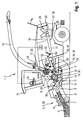
- Fig. 1 shows an executed as a forage harvester 2 agricultural machine 1, which receives in its front area as a pick-up 4 running attachment 3.
- a pick-up for example, a maize header can be used.
- the pick-up 4 is designed such that it receives a crop strand 5 between a hold-down device 6 and a pick-up drum 7 and supplies in the rear region of the pick-up 4 a cross auger 8.
- the cross auger 8 passes the crop 5 almost centrally of the pick-up 4 downstream Einzugorganen 9.
- the retraction members 9 are formed by paired feed rollers 10 and this downstream pre-compression rollers 11. After the crop strand 5 has passed the intake elements 9, it is transferred to a chopper drum 12 in the rear region thereof.
- the chopper drum 12 receives at its periphery a plurality of chopping blades 13, which the Erntegutstrang 5 crushed in cooperation with a counter-blade 14. Due to the kinetic energy of the rotating chopper drum 12, the crop strand 5 emerges at high speed from the chopper drum 12 in the rear region thereof and is transferred to cracker rollers 15 arranged in pairs.
- the cracker rollers 15 form a so-called post-shredding device 16, which can optionally be used. After the crop strand 5 has passed the post-shredding device 16, it passes into the effective range of a post-accelerator 17.
- the post-accelerator 17 imposes additional kinetic energy on the crop strand 5 in a manner known per se, by means of which the crop strand 5 is directed via a discharge chute pointing essentially in the vertical direction 18 and a subordinate pivoting and rotating ejection elbow 19 is conveyed out of the forage harvester 2.
- the attachment 3, the intake organs 9, the chopper drum 12, the optional post-shredding device 16, and the post-accelerator 17 form the working members 20 of the agricultural machine 1 according to the invention.
- the forage harvester 2 is associated with at least one drive motor 25, the output side pulley 26 is wrapped by a drive belt 27.
- the main drive belt 28 extends between the output side pulley 26 of the drive motor 25 and one of the drive shaft 29 of the chopper drum 12 associated pulley 30.
- the so-called Switzerland 31 directly between the chopper drum 12th and the pulley 26 of the drive motor 25 extends and is free of further energieabietyden elements, the other in the following to be described in more detail 32 and clamping devices 33 are arranged in the so-called Leertrum 34.
- the chopper drum 12 is supplied with drive power pulley 30 in the vertical direction deeper than the drive motor 25 associated pulley 26.
- the input and output unit 24 of the control unit 23 is designed, for example, as a keyboard and a display unit.
- Fig. 2 is a schematic view of a drive system shown in plan view.
- a pulley 36 is disposed on the Nachbeschreiberwelle 35, which is at least partially wrapped by the main drive belt 28.
- the post-accelerator shaft 35 is assigned to one end a gear stage 37, by means of which the optional post-shredding device 16 can be driven.
- the gear stage 37 by means of which the optional post-shredding device 16 can be driven.
- the main drive belt 28 is assigned a further pulley 38.
- This pulley 38 is penetrated by an output shaft 39 which is coupled at one end to the drive shaft 40 of a hydraulic pump 41 designed as an axial piston pump.
- the hydraulic pump 41 is assigned a pipeline system 42 as part of a hydraulic system.
- the pipeline system 42 opens at the other end into a hydraulic motor 43, whose output shaft 44 is coupled to the input shaft 45 of a gear unit 46.
- a control valve assembly 47 is integrated into the pipeline system 42, which controls a pressure oil flow exchange between the hydraulic pump 41 and the hydraulic motor 43 in such a way that the control valve assembly 47 can interrupt the hydraulic oil flow between the hydraulic pump 41 and hydraulic motor 43, so that the intake organs 9 abruptly Come to a standstill.
- this function is required in connection with so-called foreign body detectors, since in a conventional manner on the detection of foreign bodies, the intake organs 9 are stopped, so that the detected foreign body does not enter the other working organs of the forage harvester 2. It is within the scope of the invention that the control of the pressure oil flows in a conventional manner can be carried out automatically or by an operator of the forage harvester 2 targeted.
- the gear unit 46 forms the drive unit 48 for driving the retraction members 9, wherein in a conventional manner the retraction members 9 a so-called transfer gear 49 is assigned and between the transfer gear 49 and the gear unit 46 at least one propeller shaft 50 interposed to transmit the drive energy is.
- the drive unit 48 forming the gear unit 46 is at least partially disposed in a region which is bounded in the vertical direction by the Glastrum 31 and the backbone 34 of the main drive belt 28 and also in the rear region of in FIG. 1 shown front axle 22 is located.
- the drive unit 48 of the intake organs 9 is assigned a consisting of the hydraulic pump 41 and the hydraulic motor 43 hydraulic unit 51, the speed of the intake organs 9 can be adjusted continuously.
- the hydraulic unit 51 and the gear unit 46 form the hydromechanical gear unit 52.
- the pulley 38 at the same time forms an output 32 according to the invention which cooperates with the main drive belt 28.
- FIG. 3 shows a partial sectional view of the axial piston pump designed as a hydraulic pump 41 with a valve assembly disposed thereon 67 and in a schematic representation of components of the control valve assembly 47.
- the illustration in Fig. 3 shows only a portion of a surrounding the hydraulic pump 41 housing 66 to which the arranged in a valve assembly housing 83 valve assembly 67 is connectable.
- the delivery volume and the conveying direction of the hydraulic pump 41 can be varied by changing its pivot angle, which is achieved in axial piston pumps by a change in position of their sliding disk.
- To the valve assembly 67 line of the piping system 42 can be connected to supply the hydraulic pump 41 with hydraulic oil.
- the housing 66 has an inlet 68 and a drain 69, to each of which an inlet valve 70 and an outlet valve 71 is assigned.
- the valve assembly 67 on the side of the drain 69 comprises a restriction device 72, which has a bolt 73 and a cylindrical piston 74 adjoining it.
- the bolt 73 is guided in a bolt guide 82, which is part of the limiting device 72, in the axial direction.
- An annular chamber 81 is formed between the pin guide 82 and the valve assembly housing 83 accommodating the inlet valve 70, the outlet valve 71 and the mechanical limiting device 72, among other things.
- the control valve arrangement 47 in each case comprises a first control valve 47a integrated into the pipeline system 42 and a second control valve 47b, which are each connected by hydraulic lines 84 to a tank 75.
- the intake valves 70 and the exhaust valve 71 are based on the piston longitudinal slide type.
- the respective pistons 70a, 71a of the intake valve 70 and the exhaust valve 71 are subjected to a constant hydraulic pressure in the regular operation of the intake elements 9.
- the sealing elements 70b, 71b are also pressurized, but since their surface area is smaller than that of the pistons 70a, 71a, the inlet valve 70 and the outlet valve 71 are closed.
- the pressurization of the pistons 70a, 71a to keep the intake valve 70 and the exhaust valve 71 closed, or the interruption of the pressurization to open the intake valve 70 and the exhaust valve 71, is controlled by the second control valve 47b.
- the inlet 76 is further preceded by an orifice 80, which reduces the pressure of the hydraulic oil on the piston 70 a of the inlet valve 70 side facing away.
- the piston 74 of the restriction device 72 is pressurized by means of the first control valve 47a.
- the piston surface formed by the bolt 73 and the annular guide 82 the bolt guide 82 is acted upon by a pump side pending pressure, whereby the limiting device 72 is held in an equilibrium position, the zero position of the sliding disk of the hydraulic pump 41 corresponds, that is, that no hydraulic oil is conveyed.
- This position of the bolt 73 which is adjusted by the balance of the pressure forces, is determined and adjusted by a calibration process, which is carried out with the respective hydraulic pump 41.
- the first control valve 47a also has the task of being able to retract the pin 73 of the limiting device 72, in order to achieve a corresponding direction of flow reversal of the hydraulic pump 41 with a necessary reversing of the intake organs 9.
- the first control valve 47a is switched by the control unit 23 such that the surface of the piston 74 of the restriction device 72 is pressurized.
- the force applied by the pivoting cradle counterforce from the control pressure of the reversing causes in the case of reversing that the pivot angle of the sliding disk can assume a position in which the conveying direction of the hydraulic pump 41 reverses.
- the control of the second control valve 47b remains unchanged in this situation or the second control valve 47b, if a quick stop was performed before the reversing controlled by the control unit 23 again in order to achieve this operating situation.
- FIG. 3 shows a situation of the drive system in which the retraction members 9 are operated regularly, wherein the bolt 73 of the restriction device 72 protrudes into the housing 66 of the hydraulic pump 41 to serve as a zero stop in a foreign body detection can.
- the first control valve 47a and the second control valve 47b are controlled by the control unit 23 such that the hydraulic pump 41 is in its normal operating mode for driving the intake organs 9.
- the first control valve 47a is actuated in this operating situation in order to pressurize the piston 74 with a pressurized hydraulic oil, which transfers the Bolts 73 of the limiting device 72 in its position and which corresponds to the zero position of the sliding disk 41 of the hydraulic pump.
- the inlet valve 70 and the outlet valve 71 are pressurized on the piston side, around the inlet valve 70 and the outlet valve 71 in their line sections 78, 79, the inlet 68 and outlet 69 with one on the valve assembly 67 provided inlet 76 and outlet 77 connect to keep occlusive position.
- the hydraulic oil necessary for this purpose can be provided, for example, by a constant pressure system provided on the forage harvester 2. Hydraulic oil, whose pressure is lower than the pressure on the piston side of the inlet valve 70, is also supplied through the inlet 76 on the side facing the sealing element 70b, so that the inlet valve 70 remains closed. In a corresponding manner, the outlet valve 71 is subjected to a pressure on the piston side in order to keep it in the closed position as well.
- the change in the pivot angle of the hydraulic pump 41 is limited by the projecting into the housing 66 bolt 73 in such a way that the delivery volume of the hydraulic pump 41 reaches a value of zero abruptly.
- the hydraulic oil flowing into the housing 66 through the inlet 68 causes the sliding disk of the hydraulic pump 41 to be kept in its zero position in this position, in which it is pressed against the bolt 73 on the outlet side.
- the retraction members 9 are driven reversibly in general to be able to excrete recorded foreign matter.
- the second control valve 47b is controlled by the control unit 23 in such a way that the inlet valve 70 and the outlet valve 71 are closed again, which by the pressurization of the Piston 70a, 71a is achieved.
- the first control valve 47a is actuated by the control unit 23 in order to retract the pin 73 of the limiting device 72, so that the pivoting angle of the hydraulic pump 41 can assume a value less than 0 °, which leads to a reversing of the intake elements 9.
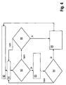
- Fig. 4 1 illustrates the method for operating the working machine 1 designed as a forage harvester 2 with reference to a flow chart.
- the first control valve 47a is actuated by the control unit 23 to transfer the limiting device 72 to its limiting position, that is, in which the limiting device 72 acts as a mechanical zero stop of the hydraulic pump 41.
- step 91 the monitoring or detection of the presence of an operating state by the control unit 23, which is representative of the penetration of a foreign body in the retraction member 9 of the work machine 2 or triggering a reversing process of the retraction member 9.
- step 92 a query is made as to whether there is an operating state which represents the penetration of a foreign body into the intake element 9. If an intrusion of a foreign body into the intake element has been detected, the second control valve 47b is actuated by the control unit 23 in step 93. The drive causes the inlet valve 70 and the outlet valve 71 to be opened. This triggers, as already stated above, the rapid stop of the hydraulic pump 41 and thus of the intake organ 9 from. In order to eliminate debris present in the intake element 9, the intake element 9 is generally reversibly driven, which is triggered manually or automatically, is detected in step 94.
- the first control valve 47a is activated in step 95 in such a way that the limiting device 72 is brought into a reversing position, that is, the function of the limiting element 72 is deactivated, such as is carried out above, so that the hydraulic pump has a negative delivery volume, which leads to a slow reversal of the intake organ 9.
- step 96 If no foreign body was detected in step 92, it is checked in step 96 whether a reversing process was triggered, which represents a common measure in the case of a crop accumulation in the intake element 9 of the forage harvester 2. If there is a signal representing the triggering of a reversing process of the retraction element 9, then the first control valve 47a is activated in such a way that the limiting device 72 is transferred into its reversing position.
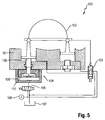
- FIG. 5 is a partial sectional view of an axial piston pump designed as a hydraulic pump 100 shown with a control valve associated therewith and a limiting device according to a second embodiment.
- the hydraulic pump 100 is arranged in a housing 101, which is shown only partially in the sectional view. Inside the housing 101 is a pivoting cradle 102, the deflection causes a change in the pivot angle of the hydraulic pump 100.
- the pivoting angle of the pivoting cradle 102 is adjustable by a solenoid valve 103.
- a limiting device 104 is arranged, which is controllable by a control valve 105.
- the limiting device 104 comprises a bolt 108 which is arranged in a housing 109 which can be flange-mounted to the housing 101.
- the bolt 108 is slidably mounted relative to the housing 109 and passes through an opening in the housing 101 of the hydraulic pump 100 in its interior.
- a bottom member 110 is arranged, which has a larger base than the bolt 108.
- the bolt 108 is connected by a screw connection to the bottom element 110.
- a pressure source 106 acts on the solenoid valve 103 or the control valve 105 with a hydraulic pressure. Furthermore, a tank 107 is provided, with which the hydraulic pump 100 is connected by lines Fig. 5 shows an operating situation of the hydraulic pump 100, in which the hydraulic pump 100 promotes no hydraulic oil due to a quick stop.
- the solenoid valve 103 is de-energized, so that the pivoting cradle 102 strives for a negative pivot angle.
- the movement of the pivoting cradle 102 is by a in the housing 101 of the Limited hydraulic pump 100 projecting piston 108, which is part of the limiting device 104.
- the control valve 105 is controlled in this operating situation such that the bolt 108 is acted upon on its side facing away from the housing 101 with a hydraulic pressure which is provided by the pressure source 106. In this way, the bolt 108 is transferred to a position corresponding to the zero stop of the hydraulic pump 100.
- Fig. 6 shows a partial sectional view of a designed as an axial piston hydraulic pump 100 with a control valve associated therewith 105 and a limiting device 104 according to the second embodiment in a second operating situation.
- the illustrated operating situation shows the hydraulic pump 100 during reversing.
- the solenoid valve 103 is also de-energized, as is the case with the rapid stop.
- the pivoting cradle 102 strives for a negative pivoting angle due to its weight distribution.
- the control valve 105 is controlled such that the hydraulic oil in the housing 109, with which the bolt 108 is acted upon, can flow into the tank 107.
- the pin 108 Due to the weight of the pivoting cradle 102 and the lack of back pressure, the pin 108 is pushed out of the interior of the housing 101. Due to the omission of the mechanical stop inside the housing 101 of the hydraulic pump 100, the pivoting cradle assumes a negative pivoting angle.
Landscapes
- Engineering & Computer Science (AREA)
- Mechanical Engineering (AREA)
- General Engineering & Computer Science (AREA)
- Life Sciences & Earth Sciences (AREA)
- Environmental Sciences (AREA)
- Chemical & Material Sciences (AREA)
- Analytical Chemistry (AREA)
- Physics & Mathematics (AREA)
- Fluid Mechanics (AREA)
- Fluid-Pressure Circuits (AREA)
Claims (14)
- Système d'entraînement pour des organes de travail (9) entraînés hydrauliquement d'une machine de travail (2), comprenant une pompe à pistons axiaux (41) dont on peut faire varier le volume déplacé et le sens de refoulement par modification de son angle d'inclinaison, un moteur hydraulique qui relié par une conduite à la pompe à pistons axiaux (41, 100) et qui est en liaison d'entraînement avec les organes de travail (9), ainsi qu'une unité de commande (23) que l'on peut faire fonctionner pour mettre à zéro le volume déplacé de la pompe à pistons axiaux (41) par activation d'une électrovanne (103), caractérisé en ce que le système d'entraînement comporte un actionneur (47), lequel est activable par l'unité de commande (23) et permet d'activer un dispositif de limitation (72, 104) qui comporte un élément en forme de piston (73, 74) pouvant être soumis au moins d'un côté à une pression hydraulique et qui permet de fixer mécaniquement à zéro degré (0°) l'angle d'inclinaison de la pompe à pistons axiaux (41, 100).
- Système d'entraînement selon la revendication 1, caractérisé en ce que l'actionneur est réalisé sous la forme d'une soupape de commande (105).
- Système d'entraînement selon l'une des revendications 1 ou 2, caractérisé en ce que le dispositif de limitation (72, 104) est intégré à la pompe à pistons axiaux (41, 100).
- Système d'entraînement selon la revendication 1, caractérisé en ce que l'actionneur est conçu sous la forme d'un ensemble soupapes de commande (47).
- Système d'entraînement selon la revendication 4, caractérisé en ce que l'ensemble soupapes de commande (47) comprend un bloc de soupapes (67) ainsi qu'une première et une deuxième soupape de commande (47a, 47b).
- Système d'entraînement selon la revendication 5, caractérisé en ce que le bloc de soupapes (67) comprend un boîtier de bloc de soupapes (83) dans lequel sont disposés une soupape d'entrée (70), une soupape de sortie (71) et le dispositif de limitation (72).
- Système d'entraînement selon l'une des revendications 5 ou 6, caractérisé en ce que le dispositif de limitation (72) peut être activé par la première soupape de commande (47a).
- Système d'entraînement selon l'une des revendications 5 à 7, caractérisé en ce que la deuxième soupape de commande (47b) active la soupape d'entrée (70) et la soupape de sortie (71), lesquelles commandent l'amenée et l'évacuation d'huile hydraulique vers, respectivement de, la pompe à pistons axiaux (41).
- Système d'entraînement selon l'une des revendications 1 à 8, caractérisé en ce que le dispositif de limitation (72) est réglable de façon que le sens de refoulement de la pompe à pistons axiaux (41) soit réversible.
- Système d'entraînement selon l'une des revendications 1 à 9, caractérisé en ce que l'unité de commande (23) est conçue pour détecter un état de fonctionnement de la machine de travail représentatif de la pénétration d'un corps étranger dans un organe de travail (9) de la machine de travail (1) ou d'un déclenchement d'une inversion de marche d'un organe de travail (9).
- Procédé pour faire fonctionner un système d'entraînement pour des organes de travail (9) entraînés hydrauliquement d'une machine de travail (2), comprenant une pompe à pistons axiaux (41) dont on fait varier le volume déplacé et le sens de refoulement par modification de son angle d'inclinaison, un moteur hydraulique relié par une conduite à la pompe à pistons axiaux (41), qui est en liaison d'entraînement avec les organes de travail (9), ainsi qu'une unité de commande (23) que l'on peut faire fonctionner de façon que le volume déplacé de la pompe à pistons axiaux (41) soit mis à zéro, caractérisé en ce que la présence d'un état de fonctionnement représentatif de la pénétration d'un corps étranger dans un organe de travail (9) de la machine de travail (2) ou d'un déclenchement d'une inversion de marche d'un organe de travail (9) est détecté, et qu'en fonction de l'état de fonctionnement détecté, l'unité de commande (23) active un actionneur (47, 105) servant à activer un dispositif de limitation (72) qui comporte un élément en forme de piston (73, 74) pouvant être soumis au moins d'un côté à une pression hydraulique et qui permet de fixer mécaniquement l'angle d'inclinaison de la pompe à pistons axiaux (41) en fonction de l'état de fonctionnement détecté.
- Procédé selon la revendication 11, caractérisé en ce que l'unité de commande (23) active une première soupape de commande (47a) de l'ensemble soupapes de commande (47) de façon que le dispositif de limitation (72) soit transféré dans une position où l'angle d'inclinaison de la pompe à pistons axiaux (41) est fixé à zéro par le dispositif de limitation (72).
- Procédé selon l'une des revendications 11 ou 12, caractérisé en ce qu'en cas de détection du déclenchement d'une inversion de marche, la première soupape de commande (47a) de l'ensemble soupapes de commande (47) est activée de façon que le dispositif de limitation (72) soit transféré dans une position où la pompe à pistons axiaux (41) peut fonctionner de manière réversible.
- Procédé selon l'une des revendications 11 ou 12, caractérisé en ce qu'en cas de détection d'un corps étranger dans un organe de travail (9), l'unité de commande (23) active une deuxième soupape de commande (47b) de façon que la pompe à pistons axiaux (41) connaisse une inversion du sens de refoulement.
Applications Claiming Priority (1)
| Application Number | Priority Date | Filing Date | Title |
|---|---|---|---|
| DE201310110568 DE102013110568A1 (de) | 2013-09-24 | 2013-09-24 | Antriebssystem für hydraulisch angetriebene Arbeitsorgane einer Arbeitsmaschine |
Publications (2)
| Publication Number | Publication Date |
|---|---|
| EP2860397A1 EP2860397A1 (fr) | 2015-04-15 |
| EP2860397B1 true EP2860397B1 (fr) | 2016-09-14 |
Family
ID=51210295
Family Applications (1)
| Application Number | Title | Priority Date | Filing Date |
|---|---|---|---|
| EP14176986.9A Active EP2860397B1 (fr) | 2013-09-24 | 2014-07-15 | Système d'entraînement pour organes de travail entraînés hydrauliquement d'une machine de travail |
Country Status (3)
| Country | Link |
|---|---|
| US (1) | US9732773B2 (fr) |
| EP (1) | EP2860397B1 (fr) |
| DE (1) | DE102013110568A1 (fr) |
Families Citing this family (8)
| Publication number | Priority date | Publication date | Assignee | Title |
|---|---|---|---|---|
| US9955628B2 (en) * | 2015-09-25 | 2018-05-01 | Deere & Company | Reversible drive system for an agricultural machine |
| DE102015219726A1 (de) * | 2015-10-12 | 2017-04-13 | Robert Bosch Gmbh | Schrägscheibenmaschine |
| JP6625499B2 (ja) * | 2016-07-27 | 2019-12-25 | ヤンマー株式会社 | コンバイン |
| US11064653B2 (en) | 2018-06-18 | 2021-07-20 | Ag Leader Technology | Agricultural systems having stalk sensors and data visualization systems and related devices and methods |
| US12495736B2 (en) * | 2019-09-04 | 2025-12-16 | Ag Leader Technology | Apparatus, systems and methods for stalk sensing |
| US11758848B2 (en) | 2020-04-08 | 2023-09-19 | Ag Leader Technology | Devices, systems, and methods for sensing the cross-sectional area of stalks |
| US12414505B2 (en) | 2020-09-04 | 2025-09-16 | Ag Leader Technology | Harvesting system for row-by-row control of a harvester |
| DE102022130293A1 (de) * | 2022-11-16 | 2024-05-16 | Claas Selbstfahrende Erntemaschinen Gmbh | Selbstfahrende Erntemaschine |
Family Cites Families (5)
| Publication number | Priority date | Publication date | Assignee | Title |
|---|---|---|---|---|
| US3810715A (en) * | 1972-08-07 | 1974-05-14 | Gen Motors Corp | Hydrostatic machine valve biasing system |
| DE19540654C1 (de) * | 1995-10-31 | 1996-12-19 | Brueninghaus Hydromatik Gmbh | Verstellvorrichtung mit hydraulischer Zentriereinrichtung |
| EP2138720A3 (fr) * | 2008-06-24 | 2010-01-20 | MALI Holding AG | Dispositif de réglage pour le réglage de machines à pistons axiaux. |
| DE102009002849A1 (de) | 2008-07-11 | 2010-01-14 | Deere & Company, Moline | Antriebssystem für einen Einzugsförderer einer Erntemaschine |
| DE102012218446A1 (de) * | 2012-10-10 | 2014-05-15 | Robert Bosch Gmbh | Verstellbare Axialkolbenmaschine in Schrägscheibenbauart |
-
2013
- 2013-09-24 DE DE201310110568 patent/DE102013110568A1/de not_active Withdrawn
-
2014
- 2014-07-15 EP EP14176986.9A patent/EP2860397B1/fr active Active
- 2014-09-17 US US14/488,591 patent/US9732773B2/en active Active
Also Published As
| Publication number | Publication date |
|---|---|
| EP2860397A1 (fr) | 2015-04-15 |
| US9732773B2 (en) | 2017-08-15 |
| DE102013110568A1 (de) | 2015-03-26 |
| US20150082780A1 (en) | 2015-03-26 |
Similar Documents
| Publication | Publication Date | Title |
|---|---|---|
| EP2860397B1 (fr) | Système d'entraînement pour organes de travail entraînés hydrauliquement d'une machine de travail | |
| EP2312928B1 (fr) | Système d'entraînement pour un transporteur d'alimentation de moissonneuse | |
| EP2689654B1 (fr) | Dispositif de transport et presse à balles doté d'un tel dispositif | |
| EP2653733B1 (fr) | Dispositif de serrage d'un moyen de traction d'un convoyeur | |
| EP2132973B1 (fr) | Système d'entraînement pour une machine de récolte | |
| DE2930219C2 (de) | Schubumkehr-Steuervorrichtung für Strahltriebwerke | |
| DE10303201B4 (de) | Rundballenpresse für landwirtschaftliche Halmgüter | |
| EP2944183A1 (fr) | Ramasseuse-hacheuse | |
| BE1022206B1 (de) | Antriebssystem fur einen einzugsforderer oder erntevorsatz einer erntemaschine mit richtungsabhangigem maximalmoment. | |
| EP1169907B1 (fr) | Dispositif inverseur pour machine agricole de récolte | |
| DE2712878C2 (de) | Rollballenpresse für landwirtschaftliche Halmgüter mit hydraulischer Verriegelung | |
| DE102012107227B4 (de) | Antriebssystem zum Antrieb einer Häcksel- und Einzugsvorrichtung einer Erntemaschine | |
| EP2016818A1 (fr) | Dispositif de levage et procédé de commande d'un tel dispositif de levage | |
| BE1030888B1 (de) | Antriebssystem für eine Erntemaschine | |
| DE102022135047A1 (de) | Verfahren zum schnellen Anhalten eines Zuführantriebs | |
| EP2286936B1 (fr) | Outil de presse | |
| BE1022416B1 (de) | Selbstfahrende arbeitsmaschine mit hydrostatischem fahrantrieb | |
| DE2517340A1 (de) | Rollballenpresse fuer landwirtschaftliche halmgueter mit zweiteiligem pressraumgehaeuse | |
| EP4282252B1 (fr) | Presse à balles agricole dotée d'un dispositif de serrage pour un entraînement à moyen de traction | |
| EP1595440B1 (fr) | Dispositif pour ramasser et compacter des matières récoltées | |
| DE3105408C2 (de) | Bremsventil fuer hydraulische antriebe | |
| EP4635289A1 (fr) | Ramasseuse-hacheuse automotrice | |
| EP3069596A1 (fr) | Ensileuse | |
| EP3000306A1 (fr) | Moissonneuse automotrice | |
| DE102008039863A1 (de) | Einzugsvorrichtung für einen Feldhäcksler |
Legal Events
| Date | Code | Title | Description |
|---|---|---|---|
| PUAI | Public reference made under article 153(3) epc to a published international application that has entered the european phase |
Free format text: ORIGINAL CODE: 0009012 |
|
| 17P | Request for examination filed |
Effective date: 20140715 |
|
| AK | Designated contracting states |
Kind code of ref document: A1 Designated state(s): AL AT BE BG CH CY CZ DE DK EE ES FI FR GB GR HR HU IE IS IT LI LT LU LV MC MK MT NL NO PL PT RO RS SE SI SK SM TR |
|
| AX | Request for extension of the european patent |
Extension state: BA ME |
|
| R17P | Request for examination filed (corrected) |
Effective date: 20151015 |
|
| RBV | Designated contracting states (corrected) |
Designated state(s): AL AT BE BG CH CY CZ DE DK EE ES FI FR GB GR HR HU IE IS IT LI LT LU LV MC MK MT NL NO PL PT RO RS SE SI SK SM TR |
|
| RIC1 | Information provided on ipc code assigned before grant |
Ipc: F04B 49/00 20060101ALI20160331BHEP Ipc: F04B 1/20 20060101AFI20160331BHEP |
|
| GRAP | Despatch of communication of intention to grant a patent |
Free format text: ORIGINAL CODE: EPIDOSNIGR1 |
|
| INTG | Intention to grant announced |
Effective date: 20160512 |
|
| GRAS | Grant fee paid |
Free format text: ORIGINAL CODE: EPIDOSNIGR3 |
|
| GRAA | (expected) grant |
Free format text: ORIGINAL CODE: 0009210 |
|
| AK | Designated contracting states |
Kind code of ref document: B1 Designated state(s): AL AT BE BG CH CY CZ DE DK EE ES FI FR GB GR HR HU IE IS IT LI LT LU LV MC MK MT NL NO PL PT RO RS SE SI SK SM TR |
|
| REG | Reference to a national code |
Ref country code: GB Ref legal event code: FG4D Free format text: NOT ENGLISH |
|
| REG | Reference to a national code |
Ref country code: CH Ref legal event code: EP |
|
| REG | Reference to a national code |
Ref country code: IE Ref legal event code: FG4D Free format text: LANGUAGE OF EP DOCUMENT: GERMAN |
|
| REG | Reference to a national code |
Ref country code: AT Ref legal event code: REF Ref document number: 829306 Country of ref document: AT Kind code of ref document: T Effective date: 20161015 |
|
| REG | Reference to a national code |
Ref country code: DE Ref legal event code: R096 Ref document number: 502014001437 Country of ref document: DE |
|
| RAP2 | Party data changed (patent owner data changed or rights of a patent transferred) |
Owner name: CLAAS SELBSTFAHRENDE ERNTEMASCHINEN GMBH |
|
| REG | Reference to a national code |
Ref country code: LT Ref legal event code: MG4D |
|
| REG | Reference to a national code |
Ref country code: NL Ref legal event code: MP Effective date: 20160914 |
|
| PG25 | Lapsed in a contracting state [announced via postgrant information from national office to epo] |
Ref country code: RS Free format text: LAPSE BECAUSE OF FAILURE TO SUBMIT A TRANSLATION OF THE DESCRIPTION OR TO PAY THE FEE WITHIN THE PRESCRIBED TIME-LIMIT Effective date: 20160914 Ref country code: FI Free format text: LAPSE BECAUSE OF FAILURE TO SUBMIT A TRANSLATION OF THE DESCRIPTION OR TO PAY THE FEE WITHIN THE PRESCRIBED TIME-LIMIT Effective date: 20160914 Ref country code: NO Free format text: LAPSE BECAUSE OF FAILURE TO SUBMIT A TRANSLATION OF THE DESCRIPTION OR TO PAY THE FEE WITHIN THE PRESCRIBED TIME-LIMIT Effective date: 20161214 Ref country code: HR Free format text: LAPSE BECAUSE OF FAILURE TO SUBMIT A TRANSLATION OF THE DESCRIPTION OR TO PAY THE FEE WITHIN THE PRESCRIBED TIME-LIMIT Effective date: 20160914 Ref country code: LT Free format text: LAPSE BECAUSE OF FAILURE TO SUBMIT A TRANSLATION OF THE DESCRIPTION OR TO PAY THE FEE WITHIN THE PRESCRIBED TIME-LIMIT Effective date: 20160914 |
|
| PG25 | Lapsed in a contracting state [announced via postgrant information from national office to epo] |
Ref country code: GR Free format text: LAPSE BECAUSE OF FAILURE TO SUBMIT A TRANSLATION OF THE DESCRIPTION OR TO PAY THE FEE WITHIN THE PRESCRIBED TIME-LIMIT Effective date: 20161215 Ref country code: NL Free format text: LAPSE BECAUSE OF FAILURE TO SUBMIT A TRANSLATION OF THE DESCRIPTION OR TO PAY THE FEE WITHIN THE PRESCRIBED TIME-LIMIT Effective date: 20160914 Ref country code: SE Free format text: LAPSE BECAUSE OF FAILURE TO SUBMIT A TRANSLATION OF THE DESCRIPTION OR TO PAY THE FEE WITHIN THE PRESCRIBED TIME-LIMIT Effective date: 20160914 Ref country code: LV Free format text: LAPSE BECAUSE OF FAILURE TO SUBMIT A TRANSLATION OF THE DESCRIPTION OR TO PAY THE FEE WITHIN THE PRESCRIBED TIME-LIMIT Effective date: 20160914 |
|
| PG25 | Lapsed in a contracting state [announced via postgrant information from national office to epo] |
Ref country code: EE Free format text: LAPSE BECAUSE OF FAILURE TO SUBMIT A TRANSLATION OF THE DESCRIPTION OR TO PAY THE FEE WITHIN THE PRESCRIBED TIME-LIMIT Effective date: 20160914 Ref country code: RO Free format text: LAPSE BECAUSE OF FAILURE TO SUBMIT A TRANSLATION OF THE DESCRIPTION OR TO PAY THE FEE WITHIN THE PRESCRIBED TIME-LIMIT Effective date: 20160914 |
|
| PG25 | Lapsed in a contracting state [announced via postgrant information from national office to epo] |
Ref country code: PT Free format text: LAPSE BECAUSE OF FAILURE TO SUBMIT A TRANSLATION OF THE DESCRIPTION OR TO PAY THE FEE WITHIN THE PRESCRIBED TIME-LIMIT Effective date: 20170116 Ref country code: PL Free format text: LAPSE BECAUSE OF FAILURE TO SUBMIT A TRANSLATION OF THE DESCRIPTION OR TO PAY THE FEE WITHIN THE PRESCRIBED TIME-LIMIT Effective date: 20160914 Ref country code: ES Free format text: LAPSE BECAUSE OF FAILURE TO SUBMIT A TRANSLATION OF THE DESCRIPTION OR TO PAY THE FEE WITHIN THE PRESCRIBED TIME-LIMIT Effective date: 20160914 Ref country code: CZ Free format text: LAPSE BECAUSE OF FAILURE TO SUBMIT A TRANSLATION OF THE DESCRIPTION OR TO PAY THE FEE WITHIN THE PRESCRIBED TIME-LIMIT Effective date: 20160914 Ref country code: BG Free format text: LAPSE BECAUSE OF FAILURE TO SUBMIT A TRANSLATION OF THE DESCRIPTION OR TO PAY THE FEE WITHIN THE PRESCRIBED TIME-LIMIT Effective date: 20161214 Ref country code: IS Free format text: LAPSE BECAUSE OF FAILURE TO SUBMIT A TRANSLATION OF THE DESCRIPTION OR TO PAY THE FEE WITHIN THE PRESCRIBED TIME-LIMIT Effective date: 20170114 Ref country code: SK Free format text: LAPSE BECAUSE OF FAILURE TO SUBMIT A TRANSLATION OF THE DESCRIPTION OR TO PAY THE FEE WITHIN THE PRESCRIBED TIME-LIMIT Effective date: 20160914 Ref country code: SM Free format text: LAPSE BECAUSE OF FAILURE TO SUBMIT A TRANSLATION OF THE DESCRIPTION OR TO PAY THE FEE WITHIN THE PRESCRIBED TIME-LIMIT Effective date: 20160914 |
|
| REG | Reference to a national code |
Ref country code: DE Ref legal event code: R097 Ref document number: 502014001437 Country of ref document: DE |
|
| PG25 | Lapsed in a contracting state [announced via postgrant information from national office to epo] |
Ref country code: IT Free format text: LAPSE BECAUSE OF FAILURE TO SUBMIT A TRANSLATION OF THE DESCRIPTION OR TO PAY THE FEE WITHIN THE PRESCRIBED TIME-LIMIT Effective date: 20160914 |
|
| PLBE | No opposition filed within time limit |
Free format text: ORIGINAL CODE: 0009261 |
|
| STAA | Information on the status of an ep patent application or granted ep patent |
Free format text: STATUS: NO OPPOSITION FILED WITHIN TIME LIMIT |
|
| PG25 | Lapsed in a contracting state [announced via postgrant information from national office to epo] |
Ref country code: DK Free format text: LAPSE BECAUSE OF FAILURE TO SUBMIT A TRANSLATION OF THE DESCRIPTION OR TO PAY THE FEE WITHIN THE PRESCRIBED TIME-LIMIT Effective date: 20160914 |
|
| 26N | No opposition filed |
Effective date: 20170615 |
|
| PG25 | Lapsed in a contracting state [announced via postgrant information from national office to epo] |
Ref country code: SI Free format text: LAPSE BECAUSE OF FAILURE TO SUBMIT A TRANSLATION OF THE DESCRIPTION OR TO PAY THE FEE WITHIN THE PRESCRIBED TIME-LIMIT Effective date: 20160914 |
|
| REG | Reference to a national code |
Ref country code: CH Ref legal event code: PL |
|
| REG | Reference to a national code |
Ref country code: IE Ref legal event code: MM4A |
|
| REG | Reference to a national code |
Ref country code: FR Ref legal event code: ST Effective date: 20180330 |
|
| PG25 | Lapsed in a contracting state [announced via postgrant information from national office to epo] |
Ref country code: IE Free format text: LAPSE BECAUSE OF NON-PAYMENT OF DUE FEES Effective date: 20170715 Ref country code: CH Free format text: LAPSE BECAUSE OF NON-PAYMENT OF DUE FEES Effective date: 20170731 Ref country code: LI Free format text: LAPSE BECAUSE OF NON-PAYMENT OF DUE FEES Effective date: 20170731 |
|
| PG25 | Lapsed in a contracting state [announced via postgrant information from national office to epo] |
Ref country code: FR Free format text: LAPSE BECAUSE OF NON-PAYMENT OF DUE FEES Effective date: 20170731 |
|
| PG25 | Lapsed in a contracting state [announced via postgrant information from national office to epo] |
Ref country code: LU Free format text: LAPSE BECAUSE OF NON-PAYMENT OF DUE FEES Effective date: 20170715 |
|
| PG25 | Lapsed in a contracting state [announced via postgrant information from national office to epo] |
Ref country code: MT Free format text: LAPSE BECAUSE OF FAILURE TO SUBMIT A TRANSLATION OF THE DESCRIPTION OR TO PAY THE FEE WITHIN THE PRESCRIBED TIME-LIMIT Effective date: 20160914 |
|
| PG25 | Lapsed in a contracting state [announced via postgrant information from national office to epo] |
Ref country code: AL Free format text: LAPSE BECAUSE OF FAILURE TO SUBMIT A TRANSLATION OF THE DESCRIPTION OR TO PAY THE FEE WITHIN THE PRESCRIBED TIME-LIMIT Effective date: 20160914 |
|
| GBPC | Gb: european patent ceased through non-payment of renewal fee |
Effective date: 20180715 |
|
| PG25 | Lapsed in a contracting state [announced via postgrant information from national office to epo] |
Ref country code: GB Free format text: LAPSE BECAUSE OF NON-PAYMENT OF DUE FEES Effective date: 20180715 |
|
| PG25 | Lapsed in a contracting state [announced via postgrant information from national office to epo] |
Ref country code: HU Free format text: LAPSE BECAUSE OF FAILURE TO SUBMIT A TRANSLATION OF THE DESCRIPTION OR TO PAY THE FEE WITHIN THE PRESCRIBED TIME-LIMIT; INVALID AB INITIO Effective date: 20140715 Ref country code: MC Free format text: LAPSE BECAUSE OF FAILURE TO SUBMIT A TRANSLATION OF THE DESCRIPTION OR TO PAY THE FEE WITHIN THE PRESCRIBED TIME-LIMIT Effective date: 20160914 |
|
| PG25 | Lapsed in a contracting state [announced via postgrant information from national office to epo] |
Ref country code: CY Free format text: LAPSE BECAUSE OF FAILURE TO SUBMIT A TRANSLATION OF THE DESCRIPTION OR TO PAY THE FEE WITHIN THE PRESCRIBED TIME-LIMIT Effective date: 20160914 |
|
| PG25 | Lapsed in a contracting state [announced via postgrant information from national office to epo] |
Ref country code: MK Free format text: LAPSE BECAUSE OF FAILURE TO SUBMIT A TRANSLATION OF THE DESCRIPTION OR TO PAY THE FEE WITHIN THE PRESCRIBED TIME-LIMIT Effective date: 20160914 |
|
| PG25 | Lapsed in a contracting state [announced via postgrant information from national office to epo] |
Ref country code: TR Free format text: LAPSE BECAUSE OF FAILURE TO SUBMIT A TRANSLATION OF THE DESCRIPTION OR TO PAY THE FEE WITHIN THE PRESCRIBED TIME-LIMIT Effective date: 20160914 |
|
| REG | Reference to a national code |
Ref country code: AT Ref legal event code: MM01 Ref document number: 829306 Country of ref document: AT Kind code of ref document: T Effective date: 20190715 |
|
| PG25 | Lapsed in a contracting state [announced via postgrant information from national office to epo] |
Ref country code: AT Free format text: LAPSE BECAUSE OF NON-PAYMENT OF DUE FEES Effective date: 20190715 |
|
| P01 | Opt-out of the competence of the unified patent court (upc) registered |
Effective date: 20230515 |
|
| PGFP | Annual fee paid to national office [announced via postgrant information from national office to epo] |
Ref country code: DE Payment date: 20250722 Year of fee payment: 12 |
|
| PGFP | Annual fee paid to national office [announced via postgrant information from national office to epo] |
Ref country code: BE Payment date: 20250721 Year of fee payment: 12 |