EP2860405A1 - Piezoelektrisches Dämpfungssystem für Rotor einer axialen Turbomaschine - Google Patents
Piezoelektrisches Dämpfungssystem für Rotor einer axialen Turbomaschine Download PDFInfo
- Publication number
- EP2860405A1 EP2860405A1 EP20130188506 EP13188506A EP2860405A1 EP 2860405 A1 EP2860405 A1 EP 2860405A1 EP 20130188506 EP20130188506 EP 20130188506 EP 13188506 A EP13188506 A EP 13188506A EP 2860405 A1 EP2860405 A1 EP 2860405A1
- Authority
- EP
- European Patent Office
- Prior art keywords
- rotor
- transducers
- diameters
- dissipative
- piezoelectric transducers
- Prior art date
- Legal status (The legal status is an assumption and is not a legal conclusion. Google has not performed a legal analysis and makes no representation as to the accuracy of the status listed.)
- Granted
Links
Images


Classifications
-
- F—MECHANICAL ENGINEERING; LIGHTING; HEATING; WEAPONS; BLASTING
- F04—POSITIVE - DISPLACEMENT MACHINES FOR LIQUIDS; PUMPS FOR LIQUIDS OR ELASTIC FLUIDS
- F04D—NON-POSITIVE-DISPLACEMENT PUMPS
- F04D29/00—Details, component parts, or accessories
- F04D29/66—Combating cavitation, whirls, noise, vibration or the like; Balancing
- F04D29/661—Combating cavitation, whirls, noise, vibration or the like; Balancing especially adapted for elastic fluid pumps
- F04D29/668—Combating cavitation, whirls, noise, vibration or the like; Balancing especially adapted for elastic fluid pumps damping or preventing mechanical vibrations
-
- F—MECHANICAL ENGINEERING; LIGHTING; HEATING; WEAPONS; BLASTING
- F01—MACHINES OR ENGINES IN GENERAL; ENGINE PLANTS IN GENERAL; STEAM ENGINES
- F01D—NON-POSITIVE DISPLACEMENT MACHINES OR ENGINES, e.g. STEAM TURBINES
- F01D25/00—Component parts, details, or accessories, not provided for in, or of interest apart from, other groups
- F01D25/04—Antivibration arrangements
-
- F—MECHANICAL ENGINEERING; LIGHTING; HEATING; WEAPONS; BLASTING
- F01—MACHINES OR ENGINES IN GENERAL; ENGINE PLANTS IN GENERAL; STEAM ENGINES
- F01D—NON-POSITIVE DISPLACEMENT MACHINES OR ENGINES, e.g. STEAM TURBINES
- F01D5/00—Blades; Blade-carrying members; Heating, heat-insulating, cooling or antivibration means on the blades or the members
- F01D5/02—Blade-carrying members, e.g. rotors
- F01D5/06—Rotors for more than one axial stage, e.g. of drum or multiple disc type; Details thereof, e.g. shafts, shaft connections
-
- F—MECHANICAL ENGINEERING; LIGHTING; HEATING; WEAPONS; BLASTING
- F01—MACHINES OR ENGINES IN GENERAL; ENGINE PLANTS IN GENERAL; STEAM ENGINES
- F01D—NON-POSITIVE DISPLACEMENT MACHINES OR ENGINES, e.g. STEAM TURBINES
- F01D5/00—Blades; Blade-carrying members; Heating, heat-insulating, cooling or antivibration means on the blades or the members
- F01D5/02—Blade-carrying members, e.g. rotors
- F01D5/10—Anti- vibration means
-
- F—MECHANICAL ENGINEERING; LIGHTING; HEATING; WEAPONS; BLASTING
- F04—POSITIVE - DISPLACEMENT MACHINES FOR LIQUIDS; PUMPS FOR LIQUIDS OR ELASTIC FLUIDS
- F04D—NON-POSITIVE-DISPLACEMENT PUMPS
- F04D29/00—Details, component parts, or accessories
- F04D29/66—Combating cavitation, whirls, noise, vibration or the like; Balancing
- F04D29/661—Combating cavitation, whirls, noise, vibration or the like; Balancing especially adapted for elastic fluid pumps
- F04D29/666—Combating cavitation, whirls, noise, vibration or the like; Balancing especially adapted for elastic fluid pumps by means of rotor construction or layout, e.g. unequal distribution of blades or vanes
-
- F—MECHANICAL ENGINEERING; LIGHTING; HEATING; WEAPONS; BLASTING
- F16—ENGINEERING ELEMENTS AND UNITS; GENERAL MEASURES FOR PRODUCING AND MAINTAINING EFFECTIVE FUNCTIONING OF MACHINES OR INSTALLATIONS; THERMAL INSULATION IN GENERAL
- F16F—SPRINGS; SHOCK-ABSORBERS; MEANS FOR DAMPING VIBRATION
- F16F15/00—Suppression of vibrations in systems; Means or arrangements for avoiding or reducing out-of-balance forces, e.g. due to motion
- F16F15/005—Suppression of vibrations in systems; Means or arrangements for avoiding or reducing out-of-balance forces, e.g. due to motion using electro- or magnetostrictive actuation means
-
- F—MECHANICAL ENGINEERING; LIGHTING; HEATING; WEAPONS; BLASTING
- F16—ENGINEERING ELEMENTS AND UNITS; GENERAL MEASURES FOR PRODUCING AND MAINTAINING EFFECTIVE FUNCTIONING OF MACHINES OR INSTALLATIONS; THERMAL INSULATION IN GENERAL
- F16F—SPRINGS; SHOCK-ABSORBERS; MEANS FOR DAMPING VIBRATION
- F16F15/00—Suppression of vibrations in systems; Means or arrangements for avoiding or reducing out-of-balance forces, e.g. due to motion
- F16F15/10—Suppression of vibrations in rotating systems by making use of members moving with the system
-
- H—ELECTRICITY
- H10—SEMICONDUCTOR DEVICES; ELECTRIC SOLID-STATE DEVICES NOT OTHERWISE PROVIDED FOR
- H10N—ELECTRIC SOLID-STATE DEVICES NOT OTHERWISE PROVIDED FOR
- H10N30/00—Piezoelectric or electrostrictive devices
- H10N30/30—Piezoelectric or electrostrictive devices with mechanical input and electrical output, e.g. functioning as generators or sensors
-
- F—MECHANICAL ENGINEERING; LIGHTING; HEATING; WEAPONS; BLASTING
- F05—INDEXING SCHEMES RELATING TO ENGINES OR PUMPS IN VARIOUS SUBCLASSES OF CLASSES F01-F04
- F05D—INDEXING SCHEME FOR ASPECTS RELATING TO NON-POSITIVE-DISPLACEMENT MACHINES OR ENGINES, GAS-TURBINES OR JET-PROPULSION PLANTS
- F05D2220/00—Application
- F05D2220/30—Application in turbines
- F05D2220/32—Application in turbines in gas turbines
- F05D2220/321—Application in turbines in gas turbines for a special turbine stage
- F05D2220/3216—Application in turbines in gas turbines for a special turbine stage for a special compressor stage
-
- F—MECHANICAL ENGINEERING; LIGHTING; HEATING; WEAPONS; BLASTING
- F05—INDEXING SCHEMES RELATING TO ENGINES OR PUMPS IN VARIOUS SUBCLASSES OF CLASSES F01-F04
- F05D—INDEXING SCHEME FOR ASPECTS RELATING TO NON-POSITIVE-DISPLACEMENT MACHINES OR ENGINES, GAS-TURBINES OR JET-PROPULSION PLANTS
- F05D2220/00—Application
- F05D2220/30—Application in turbines
- F05D2220/32—Application in turbines in gas turbines
- F05D2220/323—Application in turbines in gas turbines for aircraft propulsion, e.g. jet engines
-
- F—MECHANICAL ENGINEERING; LIGHTING; HEATING; WEAPONS; BLASTING
- F05—INDEXING SCHEMES RELATING TO ENGINES OR PUMPS IN VARIOUS SUBCLASSES OF CLASSES F01-F04
- F05D—INDEXING SCHEME FOR ASPECTS RELATING TO NON-POSITIVE-DISPLACEMENT MACHINES OR ENGINES, GAS-TURBINES OR JET-PROPULSION PLANTS
- F05D2260/00—Function
- F05D2260/96—Preventing, counteracting or reducing vibration or noise
-
- F—MECHANICAL ENGINEERING; LIGHTING; HEATING; WEAPONS; BLASTING
- F05—INDEXING SCHEMES RELATING TO ENGINES OR PUMPS IN VARIOUS SUBCLASSES OF CLASSES F01-F04
- F05D—INDEXING SCHEME FOR ASPECTS RELATING TO NON-POSITIVE-DISPLACEMENT MACHINES OR ENGINES, GAS-TURBINES OR JET-PROPULSION PLANTS
- F05D2270/00—Control
- F05D2270/01—Purpose of the control system
- F05D2270/11—Purpose of the control system to prolong engine life
- F05D2270/114—Purpose of the control system to prolong engine life by limiting mechanical stresses
-
- F—MECHANICAL ENGINEERING; LIGHTING; HEATING; WEAPONS; BLASTING
- F05—INDEXING SCHEMES RELATING TO ENGINES OR PUMPS IN VARIOUS SUBCLASSES OF CLASSES F01-F04
- F05D—INDEXING SCHEME FOR ASPECTS RELATING TO NON-POSITIVE-DISPLACEMENT MACHINES OR ENGINES, GAS-TURBINES OR JET-PROPULSION PLANTS
- F05D2270/00—Control
- F05D2270/30—Control parameters, e.g. input parameters
- F05D2270/334—Vibration measurements
-
- F—MECHANICAL ENGINEERING; LIGHTING; HEATING; WEAPONS; BLASTING
- F05—INDEXING SCHEMES RELATING TO ENGINES OR PUMPS IN VARIOUS SUBCLASSES OF CLASSES F01-F04
- F05D—INDEXING SCHEME FOR ASPECTS RELATING TO NON-POSITIVE-DISPLACEMENT MACHINES OR ENGINES, GAS-TURBINES OR JET-PROPULSION PLANTS
- F05D2270/00—Control
- F05D2270/60—Control system actuates means
- F05D2270/62—Electrical actuators
Definitions
- the invention relates to an axial turbomachine rotor. More specifically, the invention relates to a vibration damping system of an axial turbomachine rotor. More particularly, the invention relates to a vibration damping system of the bladed wheels of an axial turbomachine rotor with an electric dissipative circuit.
- an axial turbomachine is traversed by heterogeneous annular flows.
- any body in a homogeneous axial flow will generate variations in aerodynamic pressures in its surroundings, thus making the flow heterogeneous.
- These bodies can be, among others, blades, crank arms, variable discharge doors.
- each sudden change in pressure will be seen as a point excitation.
- the number of 360 ° excitations associated with a given rotational speed results in a particular excitation frequency. If this corresponds to a natural frequency of the rotor, then it will resonate according to a particular mode of deformation composed of a number of nodal diameters.
- a shunted piezoelectric system represents an interesting solution. This consists of a piezoelectric patch connected to a dissipative electrical circuit.
- the document JP19960861295 discloses a bladed rotor whose vibrations are reduced by means of piezoelectric patches distributed around its periphery. Each patch is associated with a closed circuit including dissipative resistance.
- the operating principle lies in the existence of deformations at the place of the piezoelectric patches, which, once deformed, generate a current dissipated by the resistors of the associated circuit.
- This mode of damping makes it possible to reduce the vibrations of a rotor and brings the same efficiency for each frequency.
- this mode of damping is not very effective for a vibration of high amplitude.
- this system requires to provide each closed circuit of components, which increases the mass and cost. The space needed to implement each circuit is penalizing.
- the invention aims to solve at least one of the problems raised by the prior art.
- the object of the invention is to improve the efficiency of a vibration damping system of a turbomachine rotor having modes with stationary or rotating diameter (s).
- Another object of the invention is to provide a vibration damping system for a turbomachine rotor that can be used as well. be effective at high frequency only at low frequency.
- the invention also aims to lighten a vibration damping system of a turbomachine rotor.
- the subject of the invention is a rotor, in particular a compressor, comprising a vibration damping system which comprises at least one set of piezoelectric transducers distributed circularly on the rotor and connected to at least one dissipative circuit, remarkable in that the piezoelectric transducers are connected so as mutualize the dissipative circuit or each of the dissipative circuits with a respective set of at least two transducers connected in parallel, the transducers of the game or each of the games being angularly distributed homogeneously on the rotor.
- the piezoelectric transducers are advantageously arranged so that each can be deformed in bending according to the deformation of the rotor at the location of the transducer in question.
- the rotor is able to deform in vibration according to a modal deformation with diameters, the number of piezoelectric transducers of the set or each set being equal to twice the number of diameter (s) of the deformed modal.
- the modal deformation with diameters essentially comprises two orthogonal deformation waves with nodal diameters, the piezoelectric transducers being angularly distributed respectively between two adjacent nodal diameters of the two deformation waves.
- two adjacent nodal diameters we mean two successive nodal diameters of the two deformation waves.
- One of the nodal diameters belonging to one of the two orthogonal deformation waves the other of the nodal diameters belonging to the other of the two deformation waves.
- the damping system comprises several sets of at least two transducers connected in parallel respectively with one of the dissipative circuits, the polarity of the transducer connections of each set being such that each of said transducers generates in their respective dissipative circuit a current of the same sign when they are deformed in the same direction.
- the damping system comprises only a set of at least two, preferably at least four transducers connected with the dissipative circuit, the polarity of the gaming transducer connections being such that each of said transducers generates in said dissipative circuit a current of the same sign when they are deformed in the same direction.
- the damping system comprises two sets of at least two transducers, said sets being angularly offset so that all the transducers of all the sets are distributed angularly in a homogeneous manner on the rotor.
- the rotor is able to deform in vibration according to a modal deformation with diameters and that the damping system comprises two sets of piezoelectric transducers which are out of phase with each other of a fraction of a turn equal to the inverse of the quadruple of the number of diameters of said modal distortion with diameters.
- the or at least one of the dissipative circuits comprises at least one inductance so as to form a resonant circuit with the transducers connected in parallel, the or at least one of the dissipative circuits preferably forming essentially an electrical circuit. closed in combination with the piezoelectric transducers of the corresponding game.
- the or at least one of the dissipative circuits is free of external power supply.
- the rotor has at least one resonant frequency ⁇ R , the dissipative circuit being a damping circuit, preferably resonant, whose frequency damping ⁇ A is equal to the resonant frequency ⁇ R of the rotor to be damped.
- the rotor is a blisk or a bladed drum.
- the blades came from materials.
- the thickness of the piezoelectric transducers represents more than 5% of the thickness of the blades, preferably more than 30%, more preferably more than 100%.
- At least one of the piezoelectric transducers is disposed on a cylindrical surface or on a surface perpendicular to the axis of rotation of the rotor, preferably outside the aerodynamic vein.
- the transducers are arranged in such a way as to deform in tension-compression resulting from bending movement of the rotor, preferably according to flexural deformations of the rotor casing.
- the invention also relates to a turbomachine comprising a rotor, which is remarkable in that the rotor is in accordance with the invention, preferably the rotor is a compressor or turbine rotor.
- the rotor when operating at a critical speed, vibrates at a resonance frequency in a diameter mode, the number of piezoelectric transducers of each set being greater than or equal to twice the number of diameters, preferably equal to four times the number of diameters of the resonance mode.
- the piezoelectric transducers are advantageously all identical.
- the invention makes it possible to exploit the symmetry of deformation of a rotor bladed wheel in a given diameter mode. By arranging piezoelectric transducers evenly 360 ° it is possible to damp a stationary or rotating vibration mode.
- the dissipative means are put in common, they serve several piezoelectric transducers. Overall efficiency is enhanced, and the possibilities of dealing with reduced frequencies are improved.
- the figure 1 represents an axial turbomachine according to the invention.
- the figure 2 is a representation of the low pressure compressor of the turbomachine of the figure 1 .
- the figure 3 illustrates a rotor according to the invention, deformed in a diameter mode (three in the example shown) with two orthogonal waves.
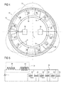
- the figure 4 represents a rotor with a vibration damping system according to the invention.
- the figure 5 traces a dissipative circuit of electrical energy according to the invention.
- inner and outer refer to a positioning relative to the axis of rotation of an axial turbomachine.
- the figure 1 schematizes an axial turbomachine. It is in this case a double-flow turbojet engine.
- the turbojet engine 2 comprises a first compression level, called a low-pressure compressor 4, a second compression level, called a high-pressure compressor 6, a combustion chamber 8 and one or more levels of turbines 10.
- the mechanical power of the turbine 10 is transmitted via the central shaft and sets in motion the two compressors 4 and 6.
- Reducing means can increase or decrease the speed of rotation transmitted to the compressors.
- the different turbine stages can each be connected to the compressor stages via concentric shafts.
- the latter comprise several rotor-shaped rotor wheels separated by stator blade wheels. The rotation of the rotored rotor wheels about their axis of rotation 14 thus makes it possible to generate an air flow and to compress it progressively until it reaches the combustion chamber 8.
- a commonly designated fan inlet fan 16 is coupled to the rotor 12 and generates a flow of air which is divided into a primary flow 18 passing through the various levels mentioned above of the turbomachine, and a secondary flow 20 passing through an annular duct (partially shown) along the machine to then join the primary flow at the turbine outlet.
- the primary 18 and secondary 20 streams are annular flows, they are channeled by the casing of the turbomachine.
- the figure 2 is a sectional view of a low-pressure compressor 4 of an axial turbomachine 2 such as that of the figure 1 .
- the rotor 12 comprises several rows of rotor blades 24, for example three.
- the low pressure compressor 4 comprises several rows of stator vanes 26, for example four.
- the rectifiers are associated with the fan 16 or a row of rotor vanes to straighten the air flow, so as to convert the speed of the flow into pressure.
- the rotor part of the low pressure compressor has a cylindrical shape commonly called drum on which the rotor blades are fixed. It has a substantially thin outer wall, its thickness may be generally less than 8.00 mm, preferably less than 5.00 mm, even more preferably less than 3.00 mm.
- the wall of the rotor 12 may have surfaces structural members extending axially and / or radially. According to an alternative of the invention, the rotor may have a monoblock disc shape with blades on its circumference.
- the drum and its blades may be made of metal material such as titanium or aluminum. They can also be made of composite materials. They are dimensioned by tolerating certain levels of static stresses that can be generated by centrifugal forces, expansion, or pressure. Their sizing also takes into account dynamic constraints generated by their vibratory responses.
- the rotor 12 can undergo dynamic excitations, among which aerodynamics represent the majority. In response, he will vibrate.
- An imbalance or a particular operating speed of the turbomachine can be a source of vibration.
- the structure of the turbomachine can communicate the vibration of another member to the rotor 12.
- the vibrations of the rotor are observed among others on the drum and its blades. They generate axial and / or radial and / or circumferential deformation of the drum walls corresponding to a particular modal composition at a given frequency.
- the structural damping remains very low. Vibratory levels and therefore associated dynamic constraints can become problematic. Indeed, the weight gain requires thinning and therefore reduce their strength and rigidity.
- the rotor 12 comprises a vibration damping system based on the use of piezoelectric transducers 28 associated with electrical energy dissipation means.
- a piezoelectric transducer 28 or piezoelectric patch is a component comprising a piezoelectric material which is able to transform a deformation into an electric current. It therefore makes it possible to convert mechanical energy into electrical energy. It is polarized and delivers a charge whose sign depends on the direction of its deformation and of its orientation.
- the piezoelectric transducers may comprise a piezoelectric composite material, for example an AFC (Active Fiber Composite). This material can be deformed so as to allow the mounting of a piezoelectric transducer on a curved surface.
- AFC Active Fiber Composite
- the piezoelectric transducers 28 are not positioned on the blades but on the surfaces available inside the drum 12, in a uniform manner at 360 °. They may be implanted on a cylindrical surface or a radial surface of the rotor 12. The rotor may have several sets of several sets of piezoelectric transducers 28 which are each distributed in a circular manner.
- the figure 3 schematically a rotor 12 seen from the front, along the axis 14.
- This figure presents a mode with diameters or modal deformation modal diameters of the rotor 12 at a resonant frequency associated ⁇ R.
- This modal deformed diameter has three diameters.
- the modal distortion with diameters essentially comprises two deformation waves 30, each of them also having the frequency ⁇ R. They are orthogonal to each other. They are fixed with respect to the rotor 12.
- the maximum amplitude of deformation of the deformation waves 30 are offset from one another. In theory, these maxima are equal. In reality they can be different from each other.
- the modal deformity corresponds to a linear combination of the two orthogonal deformation waves.
- the modal deformed material izes on the rotor 12 by a vibratory wave composed.
- the excitation is rotational relative to the rotor 12.
- the modal deformation will rotate on the rotor 12 by virtue of the combination of the two orthogonal deformation waves.
- phase shift of these deformation waves 30 is 90 °. They materialize each of the phase changes along the circumference of the rotor 12.
- the phase change points correspond to vibration nodes, where the rotor 12 undergoes no displacement and no deformation related to a given deformation wave. These points are aligned on diameters, said nodal diameters 32 of waves uniformly distributed at 360 ° for a rotor 12 with cyclic symmetry.
- the nodal diameters 32 associated with a deformation wave 30 are represented with features of the same nature: in close dotted lines for one of the deformation waves, and in dotted lines apart for the other of the deformation waves.
- the modal deformation also has nodal deformation diameters (not shown). It has as much diameter as each of its deformed.
- the nodal diameters of the deformed correspond to the places where the deformation waves 30 cancel each other out.
- These nodal deformation diameters correspond to the places where the rotor 12 undergoes no deformation. Since the modal deformation is rotating on the rotor, the nodal diameters of the deformation will also rotate.
- the number of diameters used corresponds to that of the modal deformation.
- the nodal diameters of the modal deformed are those observed physically.
- the modal deformations with excitable diameters are identified.
- the location of the nodal diameters 32 can be determined, for example depending on the location of the rotor blades. For an even number of blades and for a modal deformed having a number of diameter equal to half the number of blades, the location of the nodal diameters 32 will be between the blades. In this case, the modal deformation will be stationary. When the modal deformation has a number of diameter (s) less than half the number of blades, will be rotating.
- the damping of a modal deformed diameter can be achieved using a vibration damping system comprising a first set of piezoelectric transducers 28. These must be positioned according to the nodal diameters 32, to maximize the electromechanical coupling. They are positioned between the nodal diameters 32. This makes it possible to avoid annihilating them since, in the opposite case, two zones of the same piezoelectric transducer would produce opposite charges. Nodal areas should be avoided since they do not deform not.
- the damping system may comprise a number of piezoelectric transducers 28 equal to twice that of the diameters, for example in the case of a stationary modal deformation.
- the transducers are evenly distributed at 360 ° and are similar. They describe a circle concentric with the rotor 12. Insofar as the deformation waves 30 are out of phase, they are essentially each damped by the first set of piezoelectric transducers 28.
- the set of piezoelectric transducers 28 of the first set physically extend on less than half of the circumference.
- the vibration damping system comprises a second set of piezoelectric transducers 28.
- the second set may be similar to the first set. Its piezoelectric transducers 28 are arranged between those of the first set. Piezoelectric transducers 28 of the two games are advantageously distributed uniformly on the same circle.
- the two sets of piezoelectric transducers 28 are arranged on axially offset circles and / or different radii.
- the damping system comprises four times more piezoelectric transducers 28 than nodal diameters 32 appearing at the resonance frequency ⁇ R. Another advantage of the second game is that it avoids the amplification of a wave between the piezoelectric transducers 28 of the first game.
- the piezoelectric transducers 28 can not therefore be positioned just at the maximum of deformation. Each piezoelectric transducer will therefore be positioned in each quadrature of a deformation wave. They each occupy the majority of a quadrature of deformation.
- the piezoelectric transducers 28 of the games describe materially more than 20% of the circle they describe, preferably more than 50%; still more preferably more than 90%.
- This type of architecture will ensure, permanently and with the same efficiency, the control of the two orthogonal modes and thus of the rotating mode.
- the figure 4 schematizes a rotor 12 equipped with the vibration damping system based on the use of shunted piezoelectric transducers.
- the invention provides for defining two sets of piezoelectric transducers 28 through the branches. Each piezoelectric transducer has direct neighbors, two piezoelectric transducers of the other set.
- the invention provides that the piezoelectric transducers 28 of the same set are electrically connected to each other. To be able to accumulate their electric energies, they are connected in parallel. However, for each set, the two direct adjacent transducers of a given transducer "X" will be subjected to bending deformations in the opposite direction to said transducer "X". Therefore, some transducers will be subjected to traction and others to compression generating currents of different signs. So that the currents from each transducer 28 of the same set are of the same sign, the polarity of two neighboring transducers will be reversed. This inversion can be achieved by means of the electrical connections, or on the basis of the intrinsic polarity of the piezoelectric material that comprises the transducer 28.
- connection means 34 which may comprise wires or structural elements of the rotor 12.
- the connection means 34 of the two sets can be superposed, they are advantageously electrically isolated at crossings or over their entire length.
- Electrical connections 35 are made between the connection means 34 dedicated to the same piezoelectric transducer 28 and a collector branch. The latter can describe a circle on the rotor.
- each set of piezoelectric transducers 28 is connected to a common electrical energy dissipation circuit 36.
- This mode of The connection makes it possible to share the same dissipative circuit 36 with several piezoelectric transducers 28.
- the invention exploits the symmetry of a diameter mode in which the sets of piezoelectric transducers 28 are each deformed symmetrically. Each set of piezoelectric transducers 28 becomes a coherent current source with respect to a given deformation.
- the figure 5 illustrates an electrical circuit for connecting the piezoelectric transducers 28. It forms a closed circuit and materializes a shunt of the piezoelectric transducers 28 by means of the dissipative circuit 36.
- the dissipative circuit 36 comprises a resistor 40 for dissipating the energy in the form of heat and an inductor 42 to have a resonance of the closed circuit, for routing the energy in the circuit.
- the inductor may be a coil 42, preferably analog. It is emphasized that an analog coil is passive.
- the dissipative circuit may comprise several resistors connected in series. It can also include several inductances connected in series. These same components may be integrated in the closed circuit globally, for example on connection means 34. According to an approach of the invention, the connection means 34 may have an intrinsic resistance which is exploited to dissipate energy.
- the paralleling of the piezoelectric transducers 28 can be modeled by the paralleling capacitors of capacitance C, which act on the closed circuit as the same capacitor of single equivalent capacitance, and equal to the sum of the individual capacitors since the piezoelectric transducers 28 are connected in parallel.
- the set of piezoelectric transducers 28 of the game, the resistor 40 and the coil 42 form a resonant and damping RLC circuit.
- Its damping frequency ⁇ A is a function of the circuit capacitance C and its inductance L. This frequency is that for which the circuit will effectively act as a shock absorber.
- the choice of magnitudes of the different elements of the closed circuit is governed by the need to equal the resonance frequency of the electrical circuit ⁇ A to that of the critical mode to be damped.
- the rotor 12, the piezoelectric transducers 28 and the dissipative circuit 36 form an electromechanical system allowing a transformation of mechanical energy into electrical energy and a transfer of this mechanical energy from the rotor impeller to the electrical circuit for dissipation. energy.
- the invention facilitates the damping of the low frequency eigen modes by means of shunted circuits which can be totally passive.
- the resonance frequency of the electrical circuit, and therefore damping depends on the capacitance C of the circuit.
- the higher this capacitance the lower the necessary inductance value will be for a given frequency.
- the lower the inductance value the smaller the coil size and thus can be easily integrated into the mechanical structure. Indeed it is a totally analog element, as opposed to a synthetic inductor based on the principle of the gyrator.
- the invention thus allows a completely passive embodiment.
- the number of piezoelectric transducers is 4N distributed in two sets of 2N transducers connected to their own shunted circuit.
- the paralleling of 2N transducers therefore makes it possible, for a given resonant frequency, to reduce the size of the inductance of each circuit by a factor of 2N with respect to a damping system where each transducer is provided with an inductor.
- only two inductors are now needed instead of 4N, which again corresponds to a reduction of factor 2N. Therefore, overall, this configuration makes it possible to reduce the overall size of the inductance by a factor of 4N 2 for the same efficiency.
Landscapes
- Engineering & Computer Science (AREA)
- General Engineering & Computer Science (AREA)
- Mechanical Engineering (AREA)
- Physics & Mathematics (AREA)
- Acoustics & Sound (AREA)
- Aviation & Aerospace Engineering (AREA)
- Structures Of Non-Positive Displacement Pumps (AREA)
- Turbine Rotor Nozzle Sealing (AREA)
Priority Applications (5)
| Application Number | Priority Date | Filing Date | Title |
|---|---|---|---|
| EP13188506.3A EP2860405B1 (de) | 2013-10-14 | 2013-10-14 | Piezoelektrisches Dämpfungssystem für Rotor einer axialen Turbomaschine |
| CA2866756A CA2866756C (en) | 2013-10-14 | 2014-10-06 | Piezoelectric damper system for an axial turbomachine rotor |
| RU2014141132/06A RU2602713C2 (ru) | 2013-10-14 | 2014-10-14 | Ротор и турбомашина, содержащая указанный ротор |
| CN201410541360.2A CN104564798B (zh) | 2013-10-14 | 2014-10-14 | 用于轴向涡轮机转子的压电阻尼系统 |
| US14/514,100 US10125794B2 (en) | 2013-10-14 | 2014-10-14 | Piezoelectric damper system for an axial turbomachine rotor |
Applications Claiming Priority (1)
| Application Number | Priority Date | Filing Date | Title |
|---|---|---|---|
| EP13188506.3A EP2860405B1 (de) | 2013-10-14 | 2013-10-14 | Piezoelektrisches Dämpfungssystem für Rotor einer axialen Turbomaschine |
Publications (2)
| Publication Number | Publication Date |
|---|---|
| EP2860405A1 true EP2860405A1 (de) | 2015-04-15 |
| EP2860405B1 EP2860405B1 (de) | 2016-05-25 |
Family
ID=49328438
Family Applications (1)
| Application Number | Title | Priority Date | Filing Date |
|---|---|---|---|
| EP13188506.3A Active EP2860405B1 (de) | 2013-10-14 | 2013-10-14 | Piezoelektrisches Dämpfungssystem für Rotor einer axialen Turbomaschine |
Country Status (5)
| Country | Link |
|---|---|
| US (1) | US10125794B2 (de) |
| EP (1) | EP2860405B1 (de) |
| CN (1) | CN104564798B (de) |
| CA (1) | CA2866756C (de) |
| RU (1) | RU2602713C2 (de) |
Cited By (1)
| Publication number | Priority date | Publication date | Assignee | Title |
|---|---|---|---|---|
| CN109690027A (zh) * | 2016-09-08 | 2019-04-26 | 赛峰直升机发动机 | 一种用于通过多层压电致动器控制入口导向叶片的装置 |
Families Citing this family (10)
| Publication number | Priority date | Publication date | Assignee | Title |
|---|---|---|---|---|
| US10612401B2 (en) * | 2014-09-09 | 2020-04-07 | Rolls-Royce Corporation | Piezoelectric damping rings |
| US10557352B2 (en) * | 2014-09-09 | 2020-02-11 | Rolls-Royce Corporation | Piezoelectric damping rings |
| US10199558B2 (en) | 2016-10-22 | 2019-02-05 | Michael H. Peters | Piezoelectric power generator |
| RU2691706C2 (ru) * | 2017-05-22 | 2019-06-17 | Игорь Викторович Лентов | Способ работы многоступенчатых осевых машин |
| DE102017119870A1 (de) * | 2017-08-30 | 2019-02-28 | Rolls-Royce Deutschland Ltd & Co Kg | Schaufelanordnung einer Strömungsmaschine |
| CN108119603B (zh) * | 2017-12-07 | 2019-10-11 | 南京航空航天大学 | 一种基于压电堆叠的减振环装置 |
| FR3089585B1 (fr) * | 2018-12-07 | 2021-09-17 | Safran Helicopter Engines | Rotor de turbomachine |
| CN109578503B (zh) * | 2018-12-11 | 2024-02-13 | 南京航空航天大学 | 叉型压电堆叠减振环 |
| CN110567054B (zh) * | 2019-09-02 | 2020-09-22 | 珠海格力电器股份有限公司 | 调振组件、压缩机减振结构和空调器 |
| CN116379106A (zh) * | 2023-03-29 | 2023-07-04 | 南京航空航天大学 | 一种多级放大压电堆叠减振环 |
Citations (3)
| Publication number | Priority date | Publication date | Assignee | Title |
|---|---|---|---|---|
| JPS6166544A (ja) * | 1984-09-06 | 1986-04-05 | Toshiba Corp | 振動・騒音低減装置 |
| JPH0861295A (ja) | 1994-08-19 | 1996-03-08 | Ebara Corp | 制振機能付き羽根車 |
| US5783898A (en) * | 1996-02-26 | 1998-07-21 | Mcdonnell Douglas Corporation | Piezoelectric shunts for simultaneous vibration reduction and damping of multiple vibration modes |
Family Cites Families (6)
| Publication number | Priority date | Publication date | Assignee | Title |
|---|---|---|---|---|
| US5082421A (en) * | 1986-04-28 | 1992-01-21 | Rolls-Royce Plc | Active control of unsteady motion phenomena in turbomachinery |
| US5370340A (en) * | 1991-11-04 | 1994-12-06 | General Electric Company | Active control of aircraft engine noise using vibrational inputs |
| JPH11247605A (ja) * | 1997-12-26 | 1999-09-14 | United Technol Corp <Utc> | タ―ボマシ―ンコンポ―ネントの振動緩衝方法及び装置 |
| RU2421629C2 (ru) * | 2006-08-14 | 2011-06-20 | Роузмаунт, Инк. | Демпфер машины (варианты) и система для использования энергии вибрации, содержащая такой демпфер |
| FR2951223B1 (fr) | 2009-10-09 | 2011-12-23 | Snecma | Amortissement d'une piece tournante par dispositif piezoelectrique dissipatif semi-actif commute. |
| CN102223105B (zh) * | 2010-04-14 | 2014-05-14 | 南京航空航天大学 | 压电发电装置 |
-
2013
- 2013-10-14 EP EP13188506.3A patent/EP2860405B1/de active Active
-
2014
- 2014-10-06 CA CA2866756A patent/CA2866756C/en active Active
- 2014-10-14 RU RU2014141132/06A patent/RU2602713C2/ru active
- 2014-10-14 CN CN201410541360.2A patent/CN104564798B/zh active Active
- 2014-10-14 US US14/514,100 patent/US10125794B2/en active Active
Patent Citations (3)
| Publication number | Priority date | Publication date | Assignee | Title |
|---|---|---|---|---|
| JPS6166544A (ja) * | 1984-09-06 | 1986-04-05 | Toshiba Corp | 振動・騒音低減装置 |
| JPH0861295A (ja) | 1994-08-19 | 1996-03-08 | Ebara Corp | 制振機能付き羽根車 |
| US5783898A (en) * | 1996-02-26 | 1998-07-21 | Mcdonnell Douglas Corporation | Piezoelectric shunts for simultaneous vibration reduction and damping of multiple vibration modes |
Cited By (2)
| Publication number | Priority date | Publication date | Assignee | Title |
|---|---|---|---|---|
| CN109690027A (zh) * | 2016-09-08 | 2019-04-26 | 赛峰直升机发动机 | 一种用于通过多层压电致动器控制入口导向叶片的装置 |
| CN109690027B (zh) * | 2016-09-08 | 2021-11-30 | 赛峰直升机发动机 | 一种用于通过多层压电致动器控制入口导向叶片的装置 |
Also Published As
| Publication number | Publication date |
|---|---|
| US20150104295A1 (en) | 2015-04-16 |
| EP2860405B1 (de) | 2016-05-25 |
| RU2014141132A (ru) | 2016-05-10 |
| RU2602713C2 (ru) | 2016-11-20 |
| US10125794B2 (en) | 2018-11-13 |
| CN104564798B (zh) | 2019-01-15 |
| CA2866756C (en) | 2019-11-19 |
| CA2866756A1 (en) | 2015-04-14 |
| CN104564798A (zh) | 2015-04-29 |
Similar Documents
| Publication | Publication Date | Title |
|---|---|---|
| EP2860405B1 (de) | Piezoelektrisches Dämpfungssystem für Rotor einer axialen Turbomaschine | |
| EP1386058B1 (de) | Struktur mit einem rotor feststehenden störungsquellen und verfahren zur reduktion von vibrationen in einer solchen struktur die | |
| EP3455927B1 (de) | Elektrische maschine mit einem rotor mit einem hohlraum zum dynamischen auswuchten des rotors | |
| EP2930316B1 (de) | Verbundwerkstoffgehäuse eines Kompressors eines axialen Turbotriebwerks | |
| EP2946125B1 (de) | Aufhängungselement für die mechanische fixierung einer innerhalb einer halterung aufgehängten last | |
| FR2580044A1 (de) | ||
| EP2801702A1 (de) | Stator-Innenring eines Turbotriebwerks mit Abriebmaterial | |
| BE1025560B1 (fr) | Procede de fabrication et groupe de lubrification pour turbomachine | |
| FR2826933A1 (fr) | Amortisseur de trainee a inertie fluide pour rotor de giravion | |
| EP3286823B1 (de) | Elektrische maschine und verfahren zum dynamischen auswuchten des rotors dieser elektrischen maschine | |
| EP2873810A1 (de) | Ringförmiger Deckel zur Begrenzung der Lagerkammer eines Turbotriebwerks | |
| FR3033602A1 (fr) | Realisation d'etages de redresseurs semi-monoblocs, par fabrication additive | |
| CH620506A5 (de) | ||
| EP3594503B1 (de) | Turbotriebwerk | |
| FR3071370B1 (fr) | Isthmes de ponts magnetiques d'un rotor de machine electrique | |
| FR3044412A1 (fr) | Veine instrumentee de turbomachine | |
| US20150192019A1 (en) | Rotor train torsional mode frequency tuning apparatus | |
| FR2709214A1 (fr) | Moteur piézo-électrique à onde progressive. | |
| BE1024951A1 (fr) | Dispositif de degivrage pour aube et turbomachine axiale | |
| EP3674625B1 (de) | Kühlvorrichtung mit stirlingzyklus und motor mit externem rotor | |
| FR3012185B1 (fr) | Roue a pales d'air pour le transport et la compression d'air avec un palier d'air et compresseur radial equipe d'une telle roue. | |
| EP4291755A1 (de) | Turbomaschinenrotor mit verbessertem vibrationsverhalten | |
| EP3890163A1 (de) | Dimensionierungsverfahren eines rotors mit nicht durchgehender welle, entsprechender rotor und entsprechendes kompressoraggregat | |
| FR3052182A1 (fr) | Roue aubagee de turbomachine a comportement vibratoire ameliore | |
| FR2981205A1 (fr) | Actionneur piezoelectrique |
Legal Events
| Date | Code | Title | Description |
|---|---|---|---|
| PUAI | Public reference made under article 153(3) epc to a published international application that has entered the european phase |
Free format text: ORIGINAL CODE: 0009012 |
|
| 17P | Request for examination filed |
Effective date: 20131014 |
|
| AK | Designated contracting states |
Kind code of ref document: A1 Designated state(s): AL AT BE BG CH CY CZ DE DK EE ES FI FR GB GR HR HU IE IS IT LI LT LU LV MC MK MT NL NO PL PT RO RS SE SI SK SM TR |
|
| AX | Request for extension of the european patent |
Extension state: BA ME |
|
| R17P | Request for examination filed (corrected) |
Effective date: 20151005 |
|
| RBV | Designated contracting states (corrected) |
Designated state(s): AL AT BE BG CH CY CZ DE DK EE ES FI FR GB GR HR HU IE IS IT LI LT LU LV MC MK MT NL NO PL PT RO RS SE SI SK SM TR |
|
| GRAP | Despatch of communication of intention to grant a patent |
Free format text: ORIGINAL CODE: EPIDOSNIGR1 |
|
| RIC1 | Information provided on ipc code assigned before grant |
Ipc: F04D 29/66 20060101AFI20160201BHEP Ipc: F16F 15/00 20060101ALI20160201BHEP |
|
| INTG | Intention to grant announced |
Effective date: 20160215 |
|
| GRAS | Grant fee paid |
Free format text: ORIGINAL CODE: EPIDOSNIGR3 |
|
| GRAA | (expected) grant |
Free format text: ORIGINAL CODE: 0009210 |
|
| AK | Designated contracting states |
Kind code of ref document: B1 Designated state(s): AL AT BE BG CH CY CZ DE DK EE ES FI FR GB GR HR HU IE IS IT LI LT LU LV MC MK MT NL NO PL PT RO RS SE SI SK SM TR |
|
| REG | Reference to a national code |
Ref country code: GB Ref legal event code: FG4D Free format text: NOT ENGLISH |
|
| REG | Reference to a national code |
Ref country code: CH Ref legal event code: EP |
|
| REG | Reference to a national code |
Ref country code: IE Ref legal event code: FG4D Free format text: LANGUAGE OF EP DOCUMENT: FRENCH Ref country code: AT Ref legal event code: REF Ref document number: 802573 Country of ref document: AT Kind code of ref document: T Effective date: 20160615 |
|
| REG | Reference to a national code |
Ref country code: DE Ref legal event code: R096 Ref document number: 602013007861 Country of ref document: DE |
|
| REG | Reference to a national code |
Ref country code: FR Ref legal event code: PLFP Year of fee payment: 4 |
|
| REG | Reference to a national code |
Ref country code: LT Ref legal event code: MG4D |
|
| REG | Reference to a national code |
Ref country code: NL Ref legal event code: MP Effective date: 20160525 |
|
| PG25 | Lapsed in a contracting state [announced via postgrant information from national office to epo] |
Ref country code: NL Free format text: LAPSE BECAUSE OF FAILURE TO SUBMIT A TRANSLATION OF THE DESCRIPTION OR TO PAY THE FEE WITHIN THE PRESCRIBED TIME-LIMIT Effective date: 20160525 Ref country code: NO Free format text: LAPSE BECAUSE OF FAILURE TO SUBMIT A TRANSLATION OF THE DESCRIPTION OR TO PAY THE FEE WITHIN THE PRESCRIBED TIME-LIMIT Effective date: 20160825 Ref country code: LT Free format text: LAPSE BECAUSE OF FAILURE TO SUBMIT A TRANSLATION OF THE DESCRIPTION OR TO PAY THE FEE WITHIN THE PRESCRIBED TIME-LIMIT Effective date: 20160525 Ref country code: FI Free format text: LAPSE BECAUSE OF FAILURE TO SUBMIT A TRANSLATION OF THE DESCRIPTION OR TO PAY THE FEE WITHIN THE PRESCRIBED TIME-LIMIT Effective date: 20160525 |
|
| REG | Reference to a national code |
Ref country code: AT Ref legal event code: MK05 Ref document number: 802573 Country of ref document: AT Kind code of ref document: T Effective date: 20160525 |
|
| PG25 | Lapsed in a contracting state [announced via postgrant information from national office to epo] |
Ref country code: GR Free format text: LAPSE BECAUSE OF FAILURE TO SUBMIT A TRANSLATION OF THE DESCRIPTION OR TO PAY THE FEE WITHIN THE PRESCRIBED TIME-LIMIT Effective date: 20160826 Ref country code: LV Free format text: LAPSE BECAUSE OF FAILURE TO SUBMIT A TRANSLATION OF THE DESCRIPTION OR TO PAY THE FEE WITHIN THE PRESCRIBED TIME-LIMIT Effective date: 20160525 Ref country code: ES Free format text: LAPSE BECAUSE OF FAILURE TO SUBMIT A TRANSLATION OF THE DESCRIPTION OR TO PAY THE FEE WITHIN THE PRESCRIBED TIME-LIMIT Effective date: 20160525 Ref country code: PT Free format text: LAPSE BECAUSE OF FAILURE TO SUBMIT A TRANSLATION OF THE DESCRIPTION OR TO PAY THE FEE WITHIN THE PRESCRIBED TIME-LIMIT Effective date: 20160926 Ref country code: SE Free format text: LAPSE BECAUSE OF FAILURE TO SUBMIT A TRANSLATION OF THE DESCRIPTION OR TO PAY THE FEE WITHIN THE PRESCRIBED TIME-LIMIT Effective date: 20160525 Ref country code: RS Free format text: LAPSE BECAUSE OF FAILURE TO SUBMIT A TRANSLATION OF THE DESCRIPTION OR TO PAY THE FEE WITHIN THE PRESCRIBED TIME-LIMIT Effective date: 20160525 |
|
| REG | Reference to a national code |
Ref country code: DE Ref legal event code: R081 Ref document number: 602013007861 Country of ref document: DE Owner name: SAFRAN AERO BOOSTERS S.A., BE Free format text: FORMER OWNERS: TECHSPACE AERO S.A., HERSTAL, BE; UNIVERSITE LIBRE DE BRUXELLES, BRUESSEL/BRUXELLES, BE Ref country code: DE Ref legal event code: R081 Ref document number: 602013007861 Country of ref document: DE Owner name: UNIVERSITE LIBRE DE BRUXELLES, BE Free format text: FORMER OWNERS: TECHSPACE AERO S.A., HERSTAL, BE; UNIVERSITE LIBRE DE BRUXELLES, BRUESSEL/BRUXELLES, BE |
|
| PG25 | Lapsed in a contracting state [announced via postgrant information from national office to epo] |
Ref country code: IT Free format text: LAPSE BECAUSE OF FAILURE TO SUBMIT A TRANSLATION OF THE DESCRIPTION OR TO PAY THE FEE WITHIN THE PRESCRIBED TIME-LIMIT Effective date: 20160525 |
|
| PG25 | Lapsed in a contracting state [announced via postgrant information from national office to epo] |
Ref country code: CZ Free format text: LAPSE BECAUSE OF FAILURE TO SUBMIT A TRANSLATION OF THE DESCRIPTION OR TO PAY THE FEE WITHIN THE PRESCRIBED TIME-LIMIT Effective date: 20160525 Ref country code: SK Free format text: LAPSE BECAUSE OF FAILURE TO SUBMIT A TRANSLATION OF THE DESCRIPTION OR TO PAY THE FEE WITHIN THE PRESCRIBED TIME-LIMIT Effective date: 20160525 Ref country code: DK Free format text: LAPSE BECAUSE OF FAILURE TO SUBMIT A TRANSLATION OF THE DESCRIPTION OR TO PAY THE FEE WITHIN THE PRESCRIBED TIME-LIMIT Effective date: 20160525 Ref country code: EE Free format text: LAPSE BECAUSE OF FAILURE TO SUBMIT A TRANSLATION OF THE DESCRIPTION OR TO PAY THE FEE WITHIN THE PRESCRIBED TIME-LIMIT Effective date: 20160525 Ref country code: RO Free format text: LAPSE BECAUSE OF FAILURE TO SUBMIT A TRANSLATION OF THE DESCRIPTION OR TO PAY THE FEE WITHIN THE PRESCRIBED TIME-LIMIT Effective date: 20160525 |
|
| PG25 | Lapsed in a contracting state [announced via postgrant information from national office to epo] |
Ref country code: SM Free format text: LAPSE BECAUSE OF FAILURE TO SUBMIT A TRANSLATION OF THE DESCRIPTION OR TO PAY THE FEE WITHIN THE PRESCRIBED TIME-LIMIT Effective date: 20160525 Ref country code: AT Free format text: LAPSE BECAUSE OF FAILURE TO SUBMIT A TRANSLATION OF THE DESCRIPTION OR TO PAY THE FEE WITHIN THE PRESCRIBED TIME-LIMIT Effective date: 20160525 Ref country code: PL Free format text: LAPSE BECAUSE OF FAILURE TO SUBMIT A TRANSLATION OF THE DESCRIPTION OR TO PAY THE FEE WITHIN THE PRESCRIBED TIME-LIMIT Effective date: 20160525 |
|
| REG | Reference to a national code |
Ref country code: DE Ref legal event code: R097 Ref document number: 602013007861 Country of ref document: DE |
|
| PLBE | No opposition filed within time limit |
Free format text: ORIGINAL CODE: 0009261 |
|
| STAA | Information on the status of an ep patent application or granted ep patent |
Free format text: STATUS: NO OPPOSITION FILED WITHIN TIME LIMIT |
|
| 26N | No opposition filed |
Effective date: 20170228 |
|
| PG25 | Lapsed in a contracting state [announced via postgrant information from national office to epo] |
Ref country code: SI Free format text: LAPSE BECAUSE OF FAILURE TO SUBMIT A TRANSLATION OF THE DESCRIPTION OR TO PAY THE FEE WITHIN THE PRESCRIBED TIME-LIMIT Effective date: 20160525 |
|
| REG | Reference to a national code |
Ref country code: CH Ref legal event code: PL |
|
| REG | Reference to a national code |
Ref country code: FR Ref legal event code: CD Owner name: UNIVERSITE LIBRE DE BRUXELLES, BE Effective date: 20170606 Ref country code: FR Ref legal event code: CD Owner name: SAFRAN AERO BOOSTERS S.A., BE Effective date: 20170606 |
|
| REG | Reference to a national code |
Ref country code: IE Ref legal event code: MM4A |
|
| PG25 | Lapsed in a contracting state [announced via postgrant information from national office to epo] |
Ref country code: LI Free format text: LAPSE BECAUSE OF NON-PAYMENT OF DUE FEES Effective date: 20161031 Ref country code: CH Free format text: LAPSE BECAUSE OF NON-PAYMENT OF DUE FEES Effective date: 20161031 |
|
| PG25 | Lapsed in a contracting state [announced via postgrant information from national office to epo] |
Ref country code: LU Free format text: LAPSE BECAUSE OF NON-PAYMENT OF DUE FEES Effective date: 20161014 |
|
| REG | Reference to a national code |
Ref country code: FR Ref legal event code: PLFP Year of fee payment: 5 |
|
| PG25 | Lapsed in a contracting state [announced via postgrant information from national office to epo] |
Ref country code: IE Free format text: LAPSE BECAUSE OF NON-PAYMENT OF DUE FEES Effective date: 20161014 |
|
| PG25 | Lapsed in a contracting state [announced via postgrant information from national office to epo] |
Ref country code: HU Free format text: LAPSE BECAUSE OF FAILURE TO SUBMIT A TRANSLATION OF THE DESCRIPTION OR TO PAY THE FEE WITHIN THE PRESCRIBED TIME-LIMIT; INVALID AB INITIO Effective date: 20131014 |
|
| PG25 | Lapsed in a contracting state [announced via postgrant information from national office to epo] |
Ref country code: CY Free format text: LAPSE BECAUSE OF FAILURE TO SUBMIT A TRANSLATION OF THE DESCRIPTION OR TO PAY THE FEE WITHIN THE PRESCRIBED TIME-LIMIT Effective date: 20160525 Ref country code: MK Free format text: LAPSE BECAUSE OF FAILURE TO SUBMIT A TRANSLATION OF THE DESCRIPTION OR TO PAY THE FEE WITHIN THE PRESCRIBED TIME-LIMIT Effective date: 20160525 Ref country code: HR Free format text: LAPSE BECAUSE OF FAILURE TO SUBMIT A TRANSLATION OF THE DESCRIPTION OR TO PAY THE FEE WITHIN THE PRESCRIBED TIME-LIMIT Effective date: 20160525 Ref country code: MC Free format text: LAPSE BECAUSE OF FAILURE TO SUBMIT A TRANSLATION OF THE DESCRIPTION OR TO PAY THE FEE WITHIN THE PRESCRIBED TIME-LIMIT Effective date: 20160525 Ref country code: IS Free format text: LAPSE BECAUSE OF FAILURE TO SUBMIT A TRANSLATION OF THE DESCRIPTION OR TO PAY THE FEE WITHIN THE PRESCRIBED TIME-LIMIT Effective date: 20160525 Ref country code: MT Free format text: LAPSE BECAUSE OF FAILURE TO SUBMIT A TRANSLATION OF THE DESCRIPTION OR TO PAY THE FEE WITHIN THE PRESCRIBED TIME-LIMIT Effective date: 20160525 |
|
| PG25 | Lapsed in a contracting state [announced via postgrant information from national office to epo] |
Ref country code: BG Free format text: LAPSE BECAUSE OF FAILURE TO SUBMIT A TRANSLATION OF THE DESCRIPTION OR TO PAY THE FEE WITHIN THE PRESCRIBED TIME-LIMIT Effective date: 20160525 |
|
| REG | Reference to a national code |
Ref country code: FR Ref legal event code: PLFP Year of fee payment: 6 |
|
| PG25 | Lapsed in a contracting state [announced via postgrant information from national office to epo] |
Ref country code: AL Free format text: LAPSE BECAUSE OF FAILURE TO SUBMIT A TRANSLATION OF THE DESCRIPTION OR TO PAY THE FEE WITHIN THE PRESCRIBED TIME-LIMIT Effective date: 20160525 Ref country code: TR Free format text: LAPSE BECAUSE OF FAILURE TO SUBMIT A TRANSLATION OF THE DESCRIPTION OR TO PAY THE FEE WITHIN THE PRESCRIBED TIME-LIMIT Effective date: 20160525 |
|
| PGFP | Annual fee paid to national office [announced via postgrant information from national office to epo] |
Ref country code: DE Payment date: 20251020 Year of fee payment: 13 |
|
| PGFP | Annual fee paid to national office [announced via postgrant information from national office to epo] |
Ref country code: GB Payment date: 20251029 Year of fee payment: 13 |
|
| PGFP | Annual fee paid to national office [announced via postgrant information from national office to epo] |
Ref country code: FR Payment date: 20251024 Year of fee payment: 13 |
|
| PGFP | Annual fee paid to national office [announced via postgrant information from national office to epo] |
Ref country code: BE Payment date: 20251022 Year of fee payment: 13 |