EP2860406B1 - Akkumulator - Google Patents
Akkumulator Download PDFInfo
- Publication number
- EP2860406B1 EP2860406B1 EP13804025.8A EP13804025A EP2860406B1 EP 2860406 B1 EP2860406 B1 EP 2860406B1 EP 13804025 A EP13804025 A EP 13804025A EP 2860406 B1 EP2860406 B1 EP 2860406B1
- Authority
- EP
- European Patent Office
- Prior art keywords
- seal
- pressure
- accumulator
- seat surface
- bellows
- Prior art date
- Legal status (The legal status is an assumption and is not a legal conclusion. Google has not performed a legal analysis and makes no representation as to the accuracy of the status listed.)
- Active
Links
Images





Classifications
-
- F—MECHANICAL ENGINEERING; LIGHTING; HEATING; WEAPONS; BLASTING
- F15—FLUID-PRESSURE ACTUATORS; HYDRAULICS OR PNEUMATICS IN GENERAL
- F15B—SYSTEMS ACTING BY MEANS OF FLUIDS IN GENERAL; FLUID-PRESSURE ACTUATORS, e.g. SERVOMOTORS; DETAILS OF FLUID-PRESSURE SYSTEMS, NOT OTHERWISE PROVIDED FOR
- F15B1/00—Installations or systems with accumulators; Supply reservoir or sump assemblies
- F15B1/02—Installations or systems with accumulators
- F15B1/04—Accumulators
- F15B1/08—Accumulators using a gas cushion; Gas charging devices; Indicators or floats therefor
-
- F—MECHANICAL ENGINEERING; LIGHTING; HEATING; WEAPONS; BLASTING
- F15—FLUID-PRESSURE ACTUATORS; HYDRAULICS OR PNEUMATICS IN GENERAL
- F15B—SYSTEMS ACTING BY MEANS OF FLUIDS IN GENERAL; FLUID-PRESSURE ACTUATORS, e.g. SERVOMOTORS; DETAILS OF FLUID-PRESSURE SYSTEMS, NOT OTHERWISE PROVIDED FOR
- F15B1/00—Installations or systems with accumulators; Supply reservoir or sump assemblies
- F15B1/02—Installations or systems with accumulators
- F15B1/04—Accumulators
- F15B1/08—Accumulators using a gas cushion; Gas charging devices; Indicators or floats therefor
- F15B1/10—Accumulators using a gas cushion; Gas charging devices; Indicators or floats therefor with flexible separating means
- F15B1/103—Accumulators using a gas cushion; Gas charging devices; Indicators or floats therefor with flexible separating means the separating means being bellows
-
- F—MECHANICAL ENGINEERING; LIGHTING; HEATING; WEAPONS; BLASTING
- F15—FLUID-PRESSURE ACTUATORS; HYDRAULICS OR PNEUMATICS IN GENERAL
- F15B—SYSTEMS ACTING BY MEANS OF FLUIDS IN GENERAL; FLUID-PRESSURE ACTUATORS, e.g. SERVOMOTORS; DETAILS OF FLUID-PRESSURE SYSTEMS, NOT OTHERWISE PROVIDED FOR
- F15B20/00—Safety arrangements for fluid actuator systems; Applications of safety devices in fluid actuator systems; Emergency measures for fluid actuator systems
- F15B20/007—Overload
-
- F—MECHANICAL ENGINEERING; LIGHTING; HEATING; WEAPONS; BLASTING
- F15—FLUID-PRESSURE ACTUATORS; HYDRAULICS OR PNEUMATICS IN GENERAL
- F15B—SYSTEMS ACTING BY MEANS OF FLUIDS IN GENERAL; FLUID-PRESSURE ACTUATORS, e.g. SERVOMOTORS; DETAILS OF FLUID-PRESSURE SYSTEMS, NOT OTHERWISE PROVIDED FOR
- F15B1/00—Installations or systems with accumulators; Supply reservoir or sump assemblies
- F15B1/02—Installations or systems with accumulators
- F15B1/04—Accumulators
- F15B1/08—Accumulators using a gas cushion; Gas charging devices; Indicators or floats therefor
- F15B1/083—Accumulators using a gas cushion; Gas charging devices; Indicators or floats therefor the accumulator having a fusible plug
-
- F—MECHANICAL ENGINEERING; LIGHTING; HEATING; WEAPONS; BLASTING
- F15—FLUID-PRESSURE ACTUATORS; HYDRAULICS OR PNEUMATICS IN GENERAL
- F15B—SYSTEMS ACTING BY MEANS OF FLUIDS IN GENERAL; FLUID-PRESSURE ACTUATORS, e.g. SERVOMOTORS; DETAILS OF FLUID-PRESSURE SYSTEMS, NOT OTHERWISE PROVIDED FOR
- F15B2201/00—Accumulators
- F15B2201/20—Accumulator cushioning means
- F15B2201/205—Accumulator cushioning means using gas
-
- F—MECHANICAL ENGINEERING; LIGHTING; HEATING; WEAPONS; BLASTING
- F15—FLUID-PRESSURE ACTUATORS; HYDRAULICS OR PNEUMATICS IN GENERAL
- F15B—SYSTEMS ACTING BY MEANS OF FLUIDS IN GENERAL; FLUID-PRESSURE ACTUATORS, e.g. SERVOMOTORS; DETAILS OF FLUID-PRESSURE SYSTEMS, NOT OTHERWISE PROVIDED FOR
- F15B2201/00—Accumulators
- F15B2201/30—Accumulator separating means
- F15B2201/315—Accumulator separating means having flexible separating means
- F15B2201/3153—Accumulator separating means having flexible separating means the flexible separating means being bellows
-
- F—MECHANICAL ENGINEERING; LIGHTING; HEATING; WEAPONS; BLASTING
- F15—FLUID-PRESSURE ACTUATORS; HYDRAULICS OR PNEUMATICS IN GENERAL
- F15B—SYSTEMS ACTING BY MEANS OF FLUIDS IN GENERAL; FLUID-PRESSURE ACTUATORS, e.g. SERVOMOTORS; DETAILS OF FLUID-PRESSURE SYSTEMS, NOT OTHERWISE PROVIDED FOR
- F15B2201/00—Accumulators
- F15B2201/30—Accumulator separating means
- F15B2201/315—Accumulator separating means having flexible separating means
- F15B2201/3156—Accumulator separating means having flexible separating means characterised by their attachment
-
- F—MECHANICAL ENGINEERING; LIGHTING; HEATING; WEAPONS; BLASTING
- F15—FLUID-PRESSURE ACTUATORS; HYDRAULICS OR PNEUMATICS IN GENERAL
- F15B—SYSTEMS ACTING BY MEANS OF FLUIDS IN GENERAL; FLUID-PRESSURE ACTUATORS, e.g. SERVOMOTORS; DETAILS OF FLUID-PRESSURE SYSTEMS, NOT OTHERWISE PROVIDED FOR
- F15B2201/00—Accumulators
- F15B2201/30—Accumulator separating means
- F15B2201/315—Accumulator separating means having flexible separating means
- F15B2201/3158—Guides for the flexible separating means, e.g. for a collapsed bladder
Definitions
- the present invention relates to an accumulator which is used as a pressure accumulator or a pulsation pressure damping device.
- the accumulator according to the present invention is used, for example, in a hydraulic system for a motor vehicle or a hydraulic system for an industrial equipment.
- an accumulator 51 structured such that an accumulator housing 52 is provided with a gas filling port 54 as well as being provided with an oil port 53 which is connected to a pressure piping (not shown), an internal space of the accumulator housing 52 is sectioned into a gas chamber 57 filling the gas, and a fluid chamber 58 communicating with the oil port 53, by a bellows 55 and a bellows cap 56, and the accumulator 51 is activated to accumulate pressure and damp pulsation pressure on the basis of movement of the bellows cap 56, and extension and contraction of the bellows 55 so that gas pressure and liquid pressure balance (refer to patent document 1).
- the accumulator 51 is provided with a safety mechanism (a safety mechanism for a pressure decreasing time) 59 which prevents the bellows 55 from being damaged due to the unbalance between the gas pressure and the liquid pressure in the case that the pressure of the fluid chamber 58 is decreased together with the pressure decrease of the pressure piping.
- a safety mechanism a safety mechanism for a pressure decreasing time
- the liquid (oil) is discharged little by little from the oil port 53
- the bellows 55 is contracted little by little by the filled gas pressure according to the liquid discharge
- a seal 60 provided in a lower surface of the bellows cap 56 comes into contact with an end surface of a stay 61 so as to form a so-called zero-down state.
- the stay 61 is a metal molded part in which a liquid entrance port 61c is provided in an end surface portion 61b in a leading end of a tubular portion 61a. In the zero-down state, a part of the liquid is trapped within the fluid chamber 58 by the seal 60, and the pressure of the trapped liquid and the gas pressure of the gas chamber 57 are balanced. Therefore, the bellows 55 is inhibited from being damaged due to an excess stress applied to the bellows 55.
- the accumulator 51 is provided with a safety mechanism (an emergency safety mechanism) 62 which prevents the liquid within the fluid chamber and the gas within the gas chamber 57 from rapidly expanding in an emergency such as a fire occurrence and prevents the accumulator 51 from exploding.
- a safety mechanism an emergency safety mechanism
- a rupture disc (a weak portion) 61d provided in a part on a circumference of a peripheral surface (the tubular portion 61a) of the stay 61 bursts due to the high pressure, and the high pressure is released from the burst portion. Therefore, it is possible to inhibit an internal portion of the accumulator 51 from coming to an extremely high pressure and exploding.
- the emergency safety mechanism 62 is constructed by the rupture disc 61d which is provided in the part on the circumference of the peripheral surface (the tube portion 61a) of the stay as mentioned above, the burst pressure becomes higher (such a great pressure as to burst the metal plate is necessary). As a result, there is a disadvantage that the emergency safety mechanism 62 is not activated until the extremely high pressure is established. Further, in order to form the rupture disc 61 d in the part on the circumference of the peripheral surface (the tubular portion 61a) of the stay 61, it is necessary to press the stay 61 and thereafter additionally execute a cutting work. Therefore, there is a disadvantage that it take a lot of man hour and time to manufacture the stay 61.
- JP 2010 121637 A discloses a metal bellows accumulator having a seal holder.
- the seal holder comprises a hole.
- the hole is arranged in the central portion of the seal holder. A lower bending of the seal holder is in contact to a seat surface.
- JP 2010 151286 A discloses a metallic bellows type accumulator, in which a sealing means comprises a sealing member, made of an elastic material, in which two reinforced rings made of a metallic material are overlapped to be embedded and a holder for holding the sealing member to a side of a cap in an axially movable manner. Further, there is provided a communicating means for making a side of the liquid chamber and a side of an introducing hole communicate with each other between the overlapped surfaces of the two reinforced rings when the sealing member is reduced to ashes.
- the present invention is made by taking the above points into consideration, and an object of the present invention is to provide an accumulator provided with an emergency safety mechanism which can be activated by a lower pressure than that in the case that the rupture disc is provided in the part on the circumference of the peripheral surface of the stay.
- an accumulator according to a second aspect of the present invention is the accumulator described in the first aspect mentioned above, wherein the seal has a structure in which the rubber-like elastic body is attached to a metal member, and the second pressure release flow passage is formed between the metal member and the seat surface by engagement of the metal member with the seal holder after disappearance of the rubber-like elastic body.
- an accumulator according to a third aspect of the present invention is the accumulator described in the first aspect or the second aspect mentioned above, wherein the accumulator is an internal gas type accumulator in which the gas chamber is arranged in an inner peripheral side of the bellows and the seat surface is formed by an inner end surface of the housing, or wherein the accumulator is an external gas type accumulator in which the gas chamber is arranged in an outer peripheral side of the bellows and the seat surface is formed by an end surface of a stay fixed to the inner portion of the housing.
- the emergency safety mechanism is structured such as to communicate the fluid chamber and the oil port via the first pressure release flow passage which is formed by seating the seal holder having the concavities and convexities in the part on the circumference on the seat surface in the inner portion of the housing, and the second pressure release flow passage which is formed by the disappearance of the rubber-like elastic body of the seal due to the high temperature. Therefore, since the emergency safety mechanism is activated by the disappearance of the rubber-like elastic body of the seat without application of such a great pressure as to burst the stay, there can be provided the emergency safety mechanism which can be activated by the lower pressure in comparison with the case of bursting the stay.
- the seal can be structured such that the rubber-elastic body is attached to the metal member.
- the pressure decreasing time safety mechanism and the emergency safety mechanism are respectively activated as follows.
- the bellows cap moves in the direction of moving close to the oil port due to the high temperature and the high pressure of the liquid and the gas, and the rubber-like elastic body of the seal which is retained to the bellows cap via the seal holder disappears (is burned down).
- the seal holder seats on the seat surface in place of the rubber-like elastic body, however, since the seal holder is previously provided with the concavities and convexities in the part on the circumference, the first pressure release flow passage is formed between the seal holder and the seat surface by the concavities and convexities.
- the rubber-elastic body disappears in the seal and the seal is formed only by the metal member. Further, since the metal member stops at a position which is away from the seat surface without seating on the seat surface by the engagement with the seal holder, the second pressure release flow passage is formed between the metal member and the seat surface. Therefore, the fluid chamber is communicated with the oil port by the first and second pressure release flow passages, and the pressure within the fluid chamber is released to the pressure piping side via the oil port. Further, since the bellows is damaged by the high pressure in this state, the pressure within the gas chamber is released by the same route.
- the present invention is applied to the internal gas type accumulator in which the gas chamber is arranged in the inner peripheral side of the bellows, and is also applied to the external gas type accumulator in which the gas chamber is arranged in the outer peripheral side of the bellows.
- the seat surface on which the seal or the seal holder seats is formed by an internal end surface of the housing
- the seat surface is formed by an end surface of the stay which is fixed to the inner portion of the housing.
- the present invention achieves the following effects.
- the emergency safety mechanism since the emergency safety mechanism is activated by the application of such the high temperature as to cause the rubber-like elastic body of the seal to disappear without application of such the great pressure as to burst the stay, as mentioned above, the emergency safety mechanism is activated by the lower pressure in comparison with the prior art. Therefore, there can be provided the internal gas type accumulator or the external gas type accumulator which has a good sensitivity and can achieve an excellent explosion protection performance.
- Fig. 1 shows an accumulator 1 according to a first embodiment of the present invention.
- the accumulator 1 according to the present embodiment is a metal bellows type accumulator employing a metal bellows as a bellows 10, and is structured as follows.
- an accumulator housing 2 which is provided with an oil port 3 connected to a pressure piping (not shown) in one end (a lower end in the drawing) and is provided with a gas filling port 4 in the other end (an upper end in the drawing), the bellows 10 and a bellows cap 11 are arranged in an inner portion of the housing 2, and an inner portion of the housing 2 is sectioned into a gas chamber 12 which is filled with high-pressure gas (for example, nitrogen gas), and a fluid chamber 13 which is communicated with an oil port 3.
- a gas chamber 12 which is filled with high-pressure gas (for example, nitrogen gas)
- a fluid chamber 13 which is communicated with an oil port 3.
- the housing 2 is described as a structure which is constructed by a closed-end cylindrical shell 5, and an end cover 6 which is fixed (welded) to an one end opening portion (an upper end opening portion in the drawing) of the shell 5, however, a parts arrangement structure of the housing 2 is not particularly limited.
- the end cover 6 and the shell 5 may be integrated, and a bottom portion of the shell 5 may be constructed by an oil port member which is independent from the shell 5.
- the end cover 6 or the corresponding part is provided with the gas filling port 4 for filling the gas chamber 12 with the gas, and the gas filling port 4 is closed by a gas plug 7 after being filled with the gas.
- the bellows 10 is structured such that a fixed end (an upper end in the drawing) 10a is fixed (welded) to the end cover 6, and a discoid bellows cap 11 is fixed (welded) to a floating end (a lower end in the drawing) 10b.
- the accumulator 1 is formed as an internal gas type accumulator in which the gas chamber 12 is set in an inner peripheral side of the bellows 10 and the fluid chamber 13 is set in an outer peripheral side of the bellows 10.
- the bellows 10 may be structured such that the fixed end 10a is fixed (welded) to the bottom portion of the shell 5 and the discoid bellows cap 11 is fixed (welded) to the floating end 10b thereof.
- the accumulator is formed as an external gas type accumulator in which the gas chamber 12 is set in the outer peripheral side of the bellows 10 and the fluid chamber 13 is set in the inner peripheral side of the bellows 10.
- a damping ring 14 is attached to an outer peripheral portion of the bellows cap 11 so as to prevent the bellows 10 and the bellows cap 11 from coming into contact with the inner surface of the housing 2, however, the damping ring 14 does not serve as a sealing action.
- the accumulator 1 is provided with a pressure decreasing time safety mechanism 21 for preventing the bellows 10 from being damaged due to unbalance between the gas pressure and the liquid pressure in the case that the pressure of the fluid chamber 13 is decreased together with the pressure decrease of the pressure piping.
- the pressure decreasing time safety mechanism 21 is structured such that a seal 23 seats on a seat surface 8 in the inner portion of the housing in the case that the pressure of the fluid chamber 13 is decreased together with the pressure decrease of the pressure piping, thereby sealing the fluid chamber 13 and trapping the partial liquid in the fluid chamber 13, and is constructed as follows.
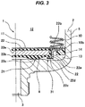
- an annular seal holder 22 is fixed to a surface (a lower surface in the drawing) close to the oil port in the bellows cap 11, the discoid seal 23 is retained by the seal holder 22, and the seal 23 seats on the seat surface 8 in the inner portion of the housing as shown in Fig. 3 by the movement of the bellows cap 11 in a direction of coming close to the oil port 3 (a downward direction in the drawing), whereby a portion between the bellows cap 11 and the housing 2 is sealed via the seal 23 and the fluid chamber 13 is occluded.
- the partial liquid is trapped within the fluid chamber 13, and the pressure of the trapped liquid is balanced with the gas pressure of the gas chamber 12, it is possible to inhibit any excessive stress from acting on the bellows 10 and inhibit the bellows 10 from being damaged.
- the seal holder 22 is constructed by a single metal molded part (a sheet metal press part, and is structured such that one end (an upper end in the drawing) of a tubular portion 22a is provided with an outward flange-like fixing portion 22b for fixing (welding) the seal holder 22 to the bellows cap 11, and the other end (a lower end in the drawing) of the tubular portion 22a is provided with an inward flange-like retaining portion 22c for retaining the seal 23.
- the seal 23 is structured such that a rubber-like elastic body 23b is attached (vulcanization bonded) to a part or a whole of a surface of the discoid metal member 23a, and a surface (a lower surface in the drawing) close to the oil port is provided with an annular seal projection 23c for making the rubber-like elastic body 23b easily reach the seat surface 8 and partly enhancing a seal surface pressure at the seating time as a part of the rubber-like elastic body 23b.
- the seat surface 8 is formed by an internal end surface of the planate housing 2 which surrounds an opening portion of the oil port 3.
- the accumulator 1 is provided with an emergency safety mechanism 31 for preventing the accumulator 1 from being exploded due to a rapid expansion of the liquid within the fluid chamber 13 and the gas within the gas chamber 12 in an emergency such as fire occurrence.
- the emergency safety mechanism 31 is structured such as to urgently release the pressure (the liquid pressure and the gas pressure) in the inner portion of the housing 2 to the oil port 3 side in the case that the inner portion of the emergency housing 2 comes to the high temperature and the high pressure due to the fire occurrence, and is constructed as follows.
- a desired number of groove portions 22d are provided (for example, four groove portions 22d are uniformly provided) in a surface (a lower surface in the drawing) seating on the seat surface 8 of the inward flange-like retaining portion 22c in the seal holder 22, the groove portions 22d passing through in a diametrical direction as concavities and convexities partly provided on a circumference.
- an outer diameter d1 of the discoid metal member 23a in the seal 23 is set to be larger than an inner diameter d2 of the inward flange-like retaining portion 22c in the seal holder 22, the metal member 23a can be engaged with the flange-like retaining portion 22c.
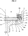
- the metal member 23a does not seat on the seat surface 8 but stops at a position which is away from the seat surface 8, and it is possible to communicate the fluid chamber 13 with the oil port 3.
- a first pressure release flow passage 32 is formed by the grooves 22d in the case that the seal holder 22 provided within the grooves 22d passing through in the diametrical direction as the partial concavities and convexities on the circumference seats on the seat surface 8, and a second pressure release flow passage 33 is formed between the metal member 23a and the seat surface 8 on the basis of the engagement in the case that the rubber-like elastic body 23b of the seal 23 is burnt down by the high temperature in an emergency. Therefore, it is possible to urgently release the internal pressure (the liquid pressure and the gas pressure) of the housing 2 to the oil port 3 side via the flow passages 31 and 32, and it is possible to inhibit the housing 2 from being exploded.
- a height position of a seat surface 8b in an inner peripheral side is set to be higher than a height position of a seat surface 8c in an outer peripheral side
- the seal 23 is set to seat on the seat surface 8b in the inner peripheral side and the seal holder 22 is set to seat on the seat surface 8c in the outer peripheral side
- a thickness t1 of the inward flange-like retaining portion 22c in the seal holder 22 is set to be larger than a height t2 of the step 8a, whereby the second pressure release flow passage 32 is secured between the metal member 23a and the seat surface 8 as shown in Fig. 4 .
- the emergency safety mechanism 31 is immediately activated by the disappearance of the rubber-like elastic body 23b of the seal 23. Therefore, since the emergency safety mechanism 31 is activated by the disappearance of the rubber-like elastic body 23b of the seal 23 without application of such a great pressure as to burst the stay in the prior art, there can be provided the emergency safety mechanism 31 which can be activated by the lower pressure in comparison with the case of bursting the stay. Further, since the seal holder 22 is manufactured only by press molding and does not require any cutting process, the seal holder 22 can be comparatively easily manufactured.
- Fig. 5 shows an accumulator 1 according to a second embodiment of the present invention.
- the accumulator 1 according to the present embodiment is a metal bellows type accumulator employing a metal bellows as a bellows 10, and is structured as follows.
- an accumulator housing 2 which is provided with an oil port 3 connected to a pressure piping (not shown) in one end (a lower end in the drawing) and is provided with a gas filling port 4 in the other end (an upper end in the drawing), the bellows 10 and a bellows cap 11 are arranged in an inner portion of the housing 2, and an inner portion of the housing 2 is sectioned into a gas chamber 12 which is filled with high-pressure gas (for example, nitrogen gas), and a fluid chamber 13 which is communicated with an oil port 3.
- a gas chamber 12 which is filled with high-pressure gas (for example, nitrogen gas)
- a fluid chamber 13 which is communicated with an oil port 3.
- the housing 2 is described as a structure which is constructed by a closed-end cylindrical shell 5, and an oil port member 9 which is fixed (welded) to an one end opening portion (a lower end opening portion in the drawing) of the shell 5, however, a parts arrangement structure of the housing 2 is not particularly limited.
- the oil port member 9 and the shell 5 may be integrated, and a bottom portion of the shell 5 may be constructed by an end cover which is independent from the shell 5.
- the bottom portion of the shell 4 or the corresponding part is provided with the gas filling port 4 for filling the gas chamber 12 with the gas, and the gas filling port 4 is closed by a gas plug 7 after being filled with the gas.
- the bellows 10 is structured such that a fixed end (a lower end in the drawing) 10a is fixed (welded) to the oil port member 9, and a discoid bellows cap 11 is fixed (welded) to a floating end (an upper end in the drawing) 10b.
- the accumulator 1 is formed as an external gas type accumulator in which the gas chamber 12 is set in an outer peripheral side of the bellows 10 and the fluid chamber 13 is set in an inner peripheral side of the bellows 10.
- the bellows 10 may be structured such that the fixed end 10a is fixed (welded) to the bottom portion of the shell 5 and the discoid bellows cap 11 is fixed (welded) to the floating end 10b thereof.
- the accumulator is formed as an internal gas type accumulator in which the gas chamber 12 is set in the inner peripheral side of the bellows 10 and the fluid chamber 13 is set in the outer peripheral side of the bellows 10.
- a damping ring 14 is attached to an outer peripheral portion of the bellows cap 11 so as to prevent the bellows 10 and the bellows cap 11 from coming into contact with the inner surface of the housing 2, however, the damping ring 14 does not serve as a sealing action.
- a stay (an internal pedestal) 16 is arranged in an inner surface of the oil port member 6 which is an inner surface close to the oil port 3 of the housing 2 in an inner peripheral side of the bellows 10, and the bellows 10 is arranged in an outer peripheral side of the stay 16.
- the stay 16 is formed by a single metal molded part (a sheet metal press part), is structured such that an end surface portion 16b is integrally formed in one end (an upper end in the drawing) of a tubular portion 16a toward an inner side in a diametrical direction, and is fixed (welded) to the inner surface of the oil port member 6 by the other end (a lower end in the drawing) of the tubular portion 16a.
- a liquid entrance port 16c is provided in the center of the end surface portion 16b which is formed into an inward flange shape.
- the accumulator 1 is provided with a pressure decreasing time safety mechanism 21 for preventing the bellows 10 from being damaged due to unbalance between the gas pressure and the liquid pressure in the case that the pressure of the fluid chamber 13 is decreased together with the pressure decrease of the pressure piping.
- the pressure decreasing time safety mechanism 21 is structured such that a seal 23 seats on a seat surface 8 which is provided in the end surface portion 16b of the stay 16 in the case that the pressure of the fluid chamber 13 is decreased together with the pressure decrease of the pressure piping, thereby sealing the fluid chamber 13 and trapping the partial liquid in the fluid chamber 13, and is constructed as follows.
- an annular seal holder 22 is fixed to a surface (a lower surface in the drawing) close to the stay in the bellows cap 11, the discoid seal 23 is retained by the seal holder 22, and the seal 23 seats on the seat surface 8 which is provided in the end surface 16b of the stay 16 as shown in Fig. 7 by the movement of the bellows cap 11 in a direction of coming close to the stay 16 (a downward direction in the drawing), whereby a portion between the bellows cap 11 and the stay 16 is sealed via the seal 23 and the fluid chamber 13 is occluded.
- the partial liquid is trapped within the fluid chamber 13, and the pressure of the trapped liquid is balanced with the gas pressure of the gas chamber 12, it is possible to inhibit any excessive stress from acting on the bellows 10 and inhibit the bellows 10 from being damaged.
- the seal holder 22 is constructed by a single metal molded part (a sheet metal press part, and is structured such that one end (an upper end in the drawing) of a tubular portion 22a is provided with an outward flange-like fixing portion 22b for fixing (welding) the seal holder 22 to the bellows cap 11, and the other end (a lower end in the drawing) of the tubular portion 22a is provided with an inward flange-like retaining portion 22c for retaining the seal 23.
- the seal 23 is structured such that a rubber-like elastic body 23b is attached (vulcanization bonded) to a part or a whole of a surface of the discoid metal member 23a, and a surface (a lower surface in the drawing) close to the oil port is provided with an annular seal projection 23c for making the rubber-like elastic body 23b easily reach the seat surface 8 and partly enhancing a seal surface pressure at the seating time as a part of the rubber-like elastic body 23b.
- the seat surface 8 is formed by the end surface of the end surface portion 16b of the stay 16, as mentioned above.
- the accumulator 1 is provided with an emergency safety mechanism 31 for preventing the accumulator 1 from being exploded due to a rapid expansion of the liquid within the fluid chamber 13 and the gas within the gas chamber 12 in an emergency such as fire occurrence.
- the emergency safety mechanism 31 is structured such as to urgently release the pressure in the inner portion of the housing 2 to the oil port 3 side in the case that the inner portion of the emergency housing 2 comes to the high temperature and the high pressure due to the fire occurrence, and is constructed as follows.
- a desired number of groove portions 22d are provided (for example, four groove portions 22d are uniformly provided) in a surface (a lower surface in the drawing) seating on the seat surface 8 of the inward flange-like retaining portion 22c in the seal holder 22, the groove portions 22d passing through in a diametrical direction as concavities and convexities partly provided on a circumference.
- an outer diameter d1 of the discoid metal member 23a in the seal 23 is set to be larger than an inner diameter d2 of the inward flange-like retaining portion 22c in the seal holder 22, the metal member 23a can be engaged with the flange-like retaining portion 22c.
- the metal member 23a does not seat on the seat surface 8 but stops at a position which is away from the seat surface 8, and it is possible to communicate the fluid chamber 13 with the oil port 3.
- a first pressure release flow passage 32 is formed by the grooves 22d in the case that the seal holder 22 provided within the grooves 22d passing through in the diametrical direction as the partial concavities and convexities on the circumference seats on the seat surface 8, and a second pressure release flow passage 33 is formed between the metal member 23a and the seat surface 8 on the basis of the engagement in the case that the rubber-like elastic body 23b of the seal 23 is burnt down by the high temperature in an emergency. Therefore, it is possible to urgently release the internal pressure (the liquid pressure and the gas pressure) of the housing 2 to the oil port 3 side via the flow passages 31 and 32, and it is possible to inhibit the housing 2 from being exploded.
- a height position of a seat surface 8b in an inner peripheral side is set to be higher than a height position of a seat surface 8c in an outer peripheral side
- the seal 23 is set to seat on the seat surface 8b in the inner peripheral side and the seal holder 22 is set to seat on the seat surface 8c in the outer peripheral side
- a thickness t1 of the inward flange-like retaining portion 22c in the seal holder 22 is set to be larger than a height t2 of the step 8a, whereby the second pressure release flow passage 32 is secured between the metal member 23a and the seat surface 8 as shown in Fig. 8 .
- the emergency safety mechanism 31 is immediately activated by the disappearance of the rubber-like elastic body 23b of the seal 23. Therefore, since the emergency safety mechanism 31 is activated by the disappearance of the rubber-like elastic body 23b of the seal 23 without application of such a great pressure as to burst the stay in the prior art, there can be provided the emergency safety mechanism 31 which can be activated by the lower pressure in comparison with the case of bursting the stay. Further, since the stay 16 and the seal holder are both manufactured only by press molding and does not require any cutting process, the seal holder 22 can be comparatively easily manufactured.
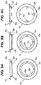
- a desired number of notches 22e are provided (for example, four notches are uniformly provided) as the partial concavities and convexities on the circumference in the inward flange-like retaining portion 22c in the seal holder 22, the notches 22e passing through in a diametrical direction.
- the notch 22e reaches a whole thickness of the retaining portion 22c.
- a desired number of projections 22f are provided (for example, four projections are uniformly provided) as the partial concavities and convexities on the circumference in the surface seating on the seat surface 8 of the inward flange-like retaining portion 22c in the seal holder 22.
- the tubular portion 22a and the inward flange-like retaining portion 22c I the seal holder 22 is divided into a plurality of pieces (for example, four uniform pieces) circumferentially, thereby forming tongue portions 22g which are formed as an L-shaped form in its cross section, and the first pressure release flow passage 32 is formed between the adjacent tongue portions 22g.
Landscapes
- Engineering & Computer Science (AREA)
- Physics & Mathematics (AREA)
- Fluid Mechanics (AREA)
- Mechanical Engineering (AREA)
- General Engineering & Computer Science (AREA)
- Chemical & Material Sciences (AREA)
- Analytical Chemistry (AREA)
- Supply Devices, Intensifiers, Converters, And Telemotors (AREA)
Claims (3)
- Speicher (1) mit:einem Speichergehäuse (2), das mit einem Ölanschluss (3) versehen ist, der mit einem Druckrohr verbunden ist, und mit einem Gaseinfüllanschluss (4) versehen ist;einem Balg (10) und einer Balgabdeckung (11), die einen Innenraum des Gehäuses in eine Gaskammer (12), in die Gas eingefüllt wird, und eine Fluidkammer (13) trennen, die mit dem Ölanschluss (3) in Kommunikation steht;einem Druckverringerungszeitpunkt-Sicherheitsmechanismus (21), der einen Dichtungshalter (22), der an der Balgabdeckung (11) fixiert ist, und eine Dichtung (23) hat, die an dem Dichtungshalter (22) gehalten wird, und die Fluidkammer (13) abdichtet, indem die Dichtung (23) auf eine Sitzfläche (8) an einem Innenabschnitt des Gehäuses in dem Fall gesetzt wird, bei dem der Druck der Fluidkammer (13) in Verbindung mit der Druckabnahme des Druckrohrs abnimmt, wobei ein Teil der Flüssigkeit in der Fluidkammer (13) eingefangen ist, wobei der Dichtungshalter (22) Konkavitäten und Konvexitäten in einem Abschnitt seines Umfangs aufweist; undeinem Notfallsicherungsmechanismus (31), der den Druck in dem Innenabschnitt des Gehäuses zu der Seite des Ölanschlusses (3) in dem Fall vordringlich öffnet, bei dem der Innenabschnitt des Gehäuses einer hohen Temperatur und einem hohen Druck in einem Notfall, wie beispielsweise einem Auftreten eines Feuers, ausgesetzt ist,wobei der Notfallsicherungsmechanismus (31) die Fluidkammer (13) und den Ölanschluss (3) über einen ersten Druckfreigabeströmungskanal (32), der ausgebildet ist, indem die Konkavitäten und Konvexitäten des Dichtungshalters (22) auf die Sitzfläche (8) gesetzt werden, und einen zweiten Druckfreigabeströmungskanal (33) in Kommunikation bringt, der ausgebildet wird durch Verschwinden eines gummiartigen elastischen Körpers (23b) der Dichtung (23) aufgrund der hohen Temperatur,wobei die Konkavitäten und Konvexitäten des Dichtungshalters (22) so ausgebildet sind, dass eine Kommunikation der Fluidkammer (13) mit dem Ölanschluss (3) errichtet wird, wenn der Dichtungshalter (22) auf der Sitzfläche (8) sitzt,wobei der Dichtungshalter (22) so aufgebaut ist, dass ein Ende eines rohrartigen Abschnittes (22a) mit einem nach außen gerichteten flanschartigen Fixierabschnitt (22b) zum Fixieren des Dichtungshalters (22) an der Balgabdeckung (11) versehen ist, und das andere Ende des rohrartigen Abschnittes (22a) mit einem nach innen gerichteten flanschartigen Halteabschnitt (22c) zum Halten der Dichtung (23) versehen ist,wobei die Dichtung (23) so aufgebaut ist, dass der gummiartige elastische Körper (23b) an einem Teil oder der Gesamtheit einer Oberfläche eines scheibenartigen Metallelementes (23a) angebracht ist, undwobei ein Außendurchmesser (d1) des scheibenartigen Metallelementes (23a) in der Dichtung (23) größer festgelegt ist als ein Innendurchmesser (d2) des nach innen gerichteten flanschartigen Halteabschnittes (22c) in dem Dichtungshalter (22), so dass das Metallelement (23a) mit dem flanschartigen Halteabschnitt (22c) in Eingriff steht,dadurch gekennzeichnet, dassNutabschnitte (22d) an einer Oberfläche, die auf die Sitzfläche (8) zu setzen ist, von dem nach innen gerichteten flanschartigen Halteabschnitt (22c) in dem Dichtungshalter (22) vorgesehen sind, wobei die Nutabschnitte (22d) in einer diametrischen Richtung als Konkavitäten und Konvexitäten hindurch treten, die abschnittsweise auf einem Umfang vorgesehen sind, undwobei in dem Fall, bei dem der gummiartige elastische Körper (23b) der Dichtung (23) aufgrund der hohen Temperatur in einem Notfall niedergebrannt ist, das Metallelement (23a) nicht auf der Sitzfläche (8) sitzt, sondern an einer Position anhält, die von der Sitzfläche (8) beabstandet ist, um die Fluidkammer (13) mit dem Ölanschluss (3) in Kommunikation zu bringen.
- Speicher (1) gemäß Anspruch 1, wobei die Dichtung (23) einen Aufbau hat, bei dem der gummiartige elastische Körper (23b) an einem Metallelement (23a) angebracht ist, und der zweite Druckfreigabeströmungskanal (33) zwischen dem Metallelement (23a) und der Sitzfläche (8) ausgebildet ist durch Eingriff des Metallelementes (23a) mit dem Sitzhalter (22) nach dem Verschwinden des gummiartigen elastischen Körpers (236).
- Speicher (1) gemäß Anspruch 1 oder 2, wobei der Speicher (1) ein Speicher der Innengasart ist, bei dem die Gaskammer (12) an einer Innenumfangsseite des Balgs (10) angeordnet ist und die Sitzfläche (8) durch eine Innenendfläche des Gehäuses ausgebildet ist, oder wobei der Speicher (1) ein Speicher der Außengasart ist, bei dem die Gaskammer (12) an einer Außenumfangsseite des Balgs (10) angeordnet ist und die Sitzfläche (8) durch eine Endfläche einer Strebe (16) ausgebildet ist, die an dem Innenabschnitt des Gehäuses fixiert ist.
Applications Claiming Priority (2)
| Application Number | Priority Date | Filing Date | Title |
|---|---|---|---|
| JP2012131830 | 2012-06-11 | ||
| PCT/JP2013/063347 WO2013187165A1 (ja) | 2012-06-11 | 2013-05-14 | アキュムレータ |
Publications (3)
| Publication Number | Publication Date |
|---|---|
| EP2860406A1 EP2860406A1 (de) | 2015-04-15 |
| EP2860406A4 EP2860406A4 (de) | 2015-08-12 |
| EP2860406B1 true EP2860406B1 (de) | 2020-01-15 |
Family
ID=49757997
Family Applications (1)
| Application Number | Title | Priority Date | Filing Date |
|---|---|---|---|
| EP13804025.8A Active EP2860406B1 (de) | 2012-06-11 | 2013-05-14 | Akkumulator |
Country Status (5)
| Country | Link |
|---|---|
| US (1) | US9188139B2 (de) |
| EP (1) | EP2860406B1 (de) |
| JP (1) | JP6121413B2 (de) |
| CN (1) | CN103998792B (de) |
| WO (1) | WO2013187165A1 (de) |
Families Citing this family (12)
| Publication number | Priority date | Publication date | Assignee | Title |
|---|---|---|---|---|
| CN104583606B (zh) * | 2013-02-15 | 2017-03-29 | 伊格尔工业股份有限公司 | 蓄能器 |
| JP5798646B2 (ja) * | 2014-02-24 | 2015-10-21 | 日本発條株式会社 | アキュムレータ |
| WO2016194607A1 (ja) | 2015-05-29 | 2016-12-08 | イーグル工業株式会社 | 金属ベローズ型アキュムレータ |
| JP6754762B2 (ja) | 2015-06-22 | 2020-09-16 | イーグル工業株式会社 | アキュムレータ |
| WO2017122481A1 (ja) * | 2016-01-13 | 2017-07-20 | イーグル工業株式会社 | アキュムレータ |
| US9689405B1 (en) * | 2016-06-03 | 2017-06-27 | Nhk Spring Co., Ltd. | Hydraulic accumulator |
| CN106523569B (zh) * | 2017-01-12 | 2019-06-25 | 常州万安汽车部件科技有限公司 | 油气减震系统 |
| JP6904983B2 (ja) * | 2017-02-03 | 2021-07-21 | イーグル工業株式会社 | アキュムレータ |
| CN110214233A (zh) * | 2017-02-03 | 2019-09-06 | 伊格尔工业股份有限公司 | 蓄能器 |
| WO2018143065A1 (ja) | 2017-02-03 | 2018-08-09 | イーグル工業株式会社 | アキュムレータ |
| DE102018007279A1 (de) * | 2018-09-14 | 2020-03-19 | Hydac Technology Gmbh | Balgspeicher |
| JP7773415B2 (ja) | 2022-03-23 | 2025-11-19 | 日本発條株式会社 | アキュムレータ |
Family Cites Families (16)
| Publication number | Priority date | Publication date | Assignee | Title |
|---|---|---|---|---|
| US3960178A (en) | 1974-09-25 | 1976-06-01 | Mercier Jacques H | Pressure vessel |
| JP3812621B2 (ja) * | 1998-10-15 | 2006-08-23 | Nok株式会社 | 端面シール |
| US6638175B2 (en) | 1999-05-12 | 2003-10-28 | Callaway Golf Company | Diagnostic golf club system |
| JP2003172301A (ja) * | 2001-12-04 | 2003-06-20 | Nhk Spring Co Ltd | アキュムレータ |
| JP2005155785A (ja) * | 2003-11-26 | 2005-06-16 | Nok Corp | アキュムレータ |
| JP4264738B2 (ja) * | 2004-03-30 | 2009-05-20 | Nok株式会社 | アキュムレータ |
| JP4384942B2 (ja) * | 2004-06-28 | 2009-12-16 | 日本発條株式会社 | アキュムレータ |
| JP4272604B2 (ja) * | 2004-08-23 | 2009-06-03 | 日本発條株式会社 | 圧力容器及び蓄圧・緩衝装置 |
| JP4862987B2 (ja) * | 2006-01-19 | 2012-01-25 | Nok株式会社 | 金属ベローズ型アキュムレータ |
| JP5201722B2 (ja) * | 2008-03-26 | 2013-06-05 | イーグル工業株式会社 | 金属ベローズ式アキュムレータ |
| JP5474333B2 (ja) * | 2008-11-05 | 2014-04-16 | イーグル工業株式会社 | アキュムレータ |
| JP5279076B2 (ja) * | 2008-11-17 | 2013-09-04 | イーグル工業株式会社 | 金属ベローズ式アキュムレータ |
| JP5108733B2 (ja) * | 2008-11-27 | 2012-12-26 | Nok株式会社 | アキュムレータ |
| JP2010151286A (ja) | 2008-12-26 | 2010-07-08 | Nok Corp | 金属ベローズ式アキュムレータ |
| JP4743292B2 (ja) | 2009-02-16 | 2011-08-10 | 美津濃株式会社 | スイング分析装置およびゴルフクラブシャフト選定システム |
| JP5535743B2 (ja) | 2009-05-01 | 2014-07-02 | イーグル工業株式会社 | 金属ベローズ |
-
2013
- 2013-05-14 WO PCT/JP2013/063347 patent/WO2013187165A1/ja not_active Ceased
- 2013-05-14 CN CN201380004228.1A patent/CN103998792B/zh active Active
- 2013-05-14 JP JP2014521027A patent/JP6121413B2/ja active Active
- 2013-05-14 US US14/366,957 patent/US9188139B2/en active Active
- 2013-05-14 EP EP13804025.8A patent/EP2860406B1/de active Active
Non-Patent Citations (1)
| Title |
|---|
| None * |
Also Published As
| Publication number | Publication date |
|---|---|
| US9188139B2 (en) | 2015-11-17 |
| US20140311604A1 (en) | 2014-10-23 |
| JP6121413B2 (ja) | 2017-04-26 |
| CN103998792B (zh) | 2016-03-30 |
| EP2860406A1 (de) | 2015-04-15 |
| WO2013187165A1 (ja) | 2013-12-19 |
| JPWO2013187165A1 (ja) | 2016-02-04 |
| EP2860406A4 (de) | 2015-08-12 |
| CN103998792A (zh) | 2014-08-20 |
Similar Documents
| Publication | Publication Date | Title |
|---|---|---|
| US9188139B2 (en) | Accumulator | |
| JP5108733B2 (ja) | アキュムレータ | |
| EP2829738B1 (de) | Akkumulator | |
| US8096324B2 (en) | Accumulator | |
| CN104583606B (zh) | 蓄能器 | |
| CN101809294B (zh) | 蓄能器 | |
| CN104863908B (zh) | 储罐 | |
| JP2010112431A (ja) | アキュムレータ | |
| JP5139959B2 (ja) | アキュムレータ | |
| JP2011226557A (ja) | アキュムレータ | |
| JP6416875B2 (ja) | アキュムレータ | |
| EP3578829B1 (de) | Akkumulator | |
| JP4956362B2 (ja) | アキュムレータ | |
| JP2009092144A (ja) | アキュムレータ | |
| EP3252318B1 (de) | Hydraulischer akkumulator | |
| US9689405B1 (en) | Hydraulic accumulator | |
| JP2012167700A (ja) | アキュムレータ | |
| JP2016151314A (ja) | アキュムレータ |
Legal Events
| Date | Code | Title | Description |
|---|---|---|---|
| PUAI | Public reference made under article 153(3) epc to a published international application that has entered the european phase |
Free format text: ORIGINAL CODE: 0009012 |
|
| 17P | Request for examination filed |
Effective date: 20140618 |
|
| AK | Designated contracting states |
Kind code of ref document: A1 Designated state(s): AL AT BE BG CH CY CZ DE DK EE ES FI FR GB GR HR HU IE IS IT LI LT LU LV MC MK MT NL NO PL PT RO RS SE SI SK SM TR |
|
| AX | Request for extension of the european patent |
Extension state: BA ME |
|
| RA4 | Supplementary search report drawn up and despatched (corrected) |
Effective date: 20150709 |
|
| RIC1 | Information provided on ipc code assigned before grant |
Ipc: F15B 20/00 20060101ALI20150703BHEP Ipc: F15B 1/10 20060101ALI20150703BHEP Ipc: F15B 1/08 20060101AFI20150703BHEP |
|
| DAX | Request for extension of the european patent (deleted) | ||
| STAA | Information on the status of an ep patent application or granted ep patent |
Free format text: STATUS: EXAMINATION IS IN PROGRESS |
|
| 17Q | First examination report despatched |
Effective date: 20180301 |
|
| GRAP | Despatch of communication of intention to grant a patent |
Free format text: ORIGINAL CODE: EPIDOSNIGR1 |
|
| STAA | Information on the status of an ep patent application or granted ep patent |
Free format text: STATUS: GRANT OF PATENT IS INTENDED |
|
| INTG | Intention to grant announced |
Effective date: 20190729 |
|
| GRAS | Grant fee paid |
Free format text: ORIGINAL CODE: EPIDOSNIGR3 |
|
| GRAA | (expected) grant |
Free format text: ORIGINAL CODE: 0009210 |
|
| STAA | Information on the status of an ep patent application or granted ep patent |
Free format text: STATUS: THE PATENT HAS BEEN GRANTED |
|
| AK | Designated contracting states |
Kind code of ref document: B1 Designated state(s): AL AT BE BG CH CY CZ DE DK EE ES FI FR GB GR HR HU IE IS IT LI LT LU LV MC MK MT NL NO PL PT RO RS SE SI SK SM TR |
|
| REG | Reference to a national code |
Ref country code: CH Ref legal event code: EP Ref country code: GB Ref legal event code: FG4D |
|
| REG | Reference to a national code |
Ref country code: IE Ref legal event code: FG4D |
|
| REG | Reference to a national code |
Ref country code: DE Ref legal event code: R096 Ref document number: 602013065159 Country of ref document: DE |
|
| REG | Reference to a national code |
Ref country code: AT Ref legal event code: REF Ref document number: 1225388 Country of ref document: AT Kind code of ref document: T Effective date: 20200215 |
|
| REG | Reference to a national code |
Ref country code: NL Ref legal event code: MP Effective date: 20200115 |
|
| REG | Reference to a national code |
Ref country code: LT Ref legal event code: MG4D |
|
| PG25 | Lapsed in a contracting state [announced via postgrant information from national office to epo] |
Ref country code: RS Free format text: LAPSE BECAUSE OF FAILURE TO SUBMIT A TRANSLATION OF THE DESCRIPTION OR TO PAY THE FEE WITHIN THE PRESCRIBED TIME-LIMIT Effective date: 20200115 Ref country code: NO Free format text: LAPSE BECAUSE OF FAILURE TO SUBMIT A TRANSLATION OF THE DESCRIPTION OR TO PAY THE FEE WITHIN THE PRESCRIBED TIME-LIMIT Effective date: 20200415 Ref country code: PT Free format text: LAPSE BECAUSE OF FAILURE TO SUBMIT A TRANSLATION OF THE DESCRIPTION OR TO PAY THE FEE WITHIN THE PRESCRIBED TIME-LIMIT Effective date: 20200607 Ref country code: FI Free format text: LAPSE BECAUSE OF FAILURE TO SUBMIT A TRANSLATION OF THE DESCRIPTION OR TO PAY THE FEE WITHIN THE PRESCRIBED TIME-LIMIT Effective date: 20200115 Ref country code: NL Free format text: LAPSE BECAUSE OF FAILURE TO SUBMIT A TRANSLATION OF THE DESCRIPTION OR TO PAY THE FEE WITHIN THE PRESCRIBED TIME-LIMIT Effective date: 20200115 |
|
| PG25 | Lapsed in a contracting state [announced via postgrant information from national office to epo] |
Ref country code: SE Free format text: LAPSE BECAUSE OF FAILURE TO SUBMIT A TRANSLATION OF THE DESCRIPTION OR TO PAY THE FEE WITHIN THE PRESCRIBED TIME-LIMIT Effective date: 20200115 Ref country code: LV Free format text: LAPSE BECAUSE OF FAILURE TO SUBMIT A TRANSLATION OF THE DESCRIPTION OR TO PAY THE FEE WITHIN THE PRESCRIBED TIME-LIMIT Effective date: 20200115 Ref country code: IS Free format text: LAPSE BECAUSE OF FAILURE TO SUBMIT A TRANSLATION OF THE DESCRIPTION OR TO PAY THE FEE WITHIN THE PRESCRIBED TIME-LIMIT Effective date: 20200515 Ref country code: GR Free format text: LAPSE BECAUSE OF FAILURE TO SUBMIT A TRANSLATION OF THE DESCRIPTION OR TO PAY THE FEE WITHIN THE PRESCRIBED TIME-LIMIT Effective date: 20200416 Ref country code: HR Free format text: LAPSE BECAUSE OF FAILURE TO SUBMIT A TRANSLATION OF THE DESCRIPTION OR TO PAY THE FEE WITHIN THE PRESCRIBED TIME-LIMIT Effective date: 20200115 Ref country code: BG Free format text: LAPSE BECAUSE OF FAILURE TO SUBMIT A TRANSLATION OF THE DESCRIPTION OR TO PAY THE FEE WITHIN THE PRESCRIBED TIME-LIMIT Effective date: 20200415 |
|
| REG | Reference to a national code |
Ref country code: DE Ref legal event code: R097 Ref document number: 602013065159 Country of ref document: DE |
|
| PG25 | Lapsed in a contracting state [announced via postgrant information from national office to epo] |
Ref country code: EE Free format text: LAPSE BECAUSE OF FAILURE TO SUBMIT A TRANSLATION OF THE DESCRIPTION OR TO PAY THE FEE WITHIN THE PRESCRIBED TIME-LIMIT Effective date: 20200115 Ref country code: LT Free format text: LAPSE BECAUSE OF FAILURE TO SUBMIT A TRANSLATION OF THE DESCRIPTION OR TO PAY THE FEE WITHIN THE PRESCRIBED TIME-LIMIT Effective date: 20200115 Ref country code: SK Free format text: LAPSE BECAUSE OF FAILURE TO SUBMIT A TRANSLATION OF THE DESCRIPTION OR TO PAY THE FEE WITHIN THE PRESCRIBED TIME-LIMIT Effective date: 20200115 Ref country code: ES Free format text: LAPSE BECAUSE OF FAILURE TO SUBMIT A TRANSLATION OF THE DESCRIPTION OR TO PAY THE FEE WITHIN THE PRESCRIBED TIME-LIMIT Effective date: 20200115 Ref country code: CZ Free format text: LAPSE BECAUSE OF FAILURE TO SUBMIT A TRANSLATION OF THE DESCRIPTION OR TO PAY THE FEE WITHIN THE PRESCRIBED TIME-LIMIT Effective date: 20200115 Ref country code: RO Free format text: LAPSE BECAUSE OF FAILURE TO SUBMIT A TRANSLATION OF THE DESCRIPTION OR TO PAY THE FEE WITHIN THE PRESCRIBED TIME-LIMIT Effective date: 20200115 Ref country code: DK Free format text: LAPSE BECAUSE OF FAILURE TO SUBMIT A TRANSLATION OF THE DESCRIPTION OR TO PAY THE FEE WITHIN THE PRESCRIBED TIME-LIMIT Effective date: 20200115 Ref country code: SM Free format text: LAPSE BECAUSE OF FAILURE TO SUBMIT A TRANSLATION OF THE DESCRIPTION OR TO PAY THE FEE WITHIN THE PRESCRIBED TIME-LIMIT Effective date: 20200115 |
|
| REG | Reference to a national code |
Ref country code: AT Ref legal event code: MK05 Ref document number: 1225388 Country of ref document: AT Kind code of ref document: T Effective date: 20200115 |
|
| PLBE | No opposition filed within time limit |
Free format text: ORIGINAL CODE: 0009261 |
|
| STAA | Information on the status of an ep patent application or granted ep patent |
Free format text: STATUS: NO OPPOSITION FILED WITHIN TIME LIMIT |
|
| 26N | No opposition filed |
Effective date: 20201016 |
|
| PG25 | Lapsed in a contracting state [announced via postgrant information from national office to epo] |
Ref country code: MC Free format text: LAPSE BECAUSE OF FAILURE TO SUBMIT A TRANSLATION OF THE DESCRIPTION OR TO PAY THE FEE WITHIN THE PRESCRIBED TIME-LIMIT Effective date: 20200115 Ref country code: CH Free format text: LAPSE BECAUSE OF NON-PAYMENT OF DUE FEES Effective date: 20200531 Ref country code: LI Free format text: LAPSE BECAUSE OF NON-PAYMENT OF DUE FEES Effective date: 20200531 Ref country code: IT Free format text: LAPSE BECAUSE OF FAILURE TO SUBMIT A TRANSLATION OF THE DESCRIPTION OR TO PAY THE FEE WITHIN THE PRESCRIBED TIME-LIMIT Effective date: 20200115 Ref country code: AT Free format text: LAPSE BECAUSE OF FAILURE TO SUBMIT A TRANSLATION OF THE DESCRIPTION OR TO PAY THE FEE WITHIN THE PRESCRIBED TIME-LIMIT Effective date: 20200115 |
|
| PG25 | Lapsed in a contracting state [announced via postgrant information from national office to epo] |
Ref country code: SI Free format text: LAPSE BECAUSE OF FAILURE TO SUBMIT A TRANSLATION OF THE DESCRIPTION OR TO PAY THE FEE WITHIN THE PRESCRIBED TIME-LIMIT Effective date: 20200115 Ref country code: PL Free format text: LAPSE BECAUSE OF FAILURE TO SUBMIT A TRANSLATION OF THE DESCRIPTION OR TO PAY THE FEE WITHIN THE PRESCRIBED TIME-LIMIT Effective date: 20200115 |
|
| REG | Reference to a national code |
Ref country code: BE Ref legal event code: MM Effective date: 20200531 |
|
| GBPC | Gb: european patent ceased through non-payment of renewal fee |
Effective date: 20200514 |
|
| PG25 | Lapsed in a contracting state [announced via postgrant information from national office to epo] |
Ref country code: LU Free format text: LAPSE BECAUSE OF NON-PAYMENT OF DUE FEES Effective date: 20200514 |
|
| PG25 | Lapsed in a contracting state [announced via postgrant information from national office to epo] |
Ref country code: GB Free format text: LAPSE BECAUSE OF NON-PAYMENT OF DUE FEES Effective date: 20200514 Ref country code: IE Free format text: LAPSE BECAUSE OF NON-PAYMENT OF DUE FEES Effective date: 20200514 Ref country code: FR Free format text: LAPSE BECAUSE OF NON-PAYMENT OF DUE FEES Effective date: 20200531 |
|
| PG25 | Lapsed in a contracting state [announced via postgrant information from national office to epo] |
Ref country code: BE Free format text: LAPSE BECAUSE OF NON-PAYMENT OF DUE FEES Effective date: 20200531 |
|
| PG25 | Lapsed in a contracting state [announced via postgrant information from national office to epo] |
Ref country code: TR Free format text: LAPSE BECAUSE OF FAILURE TO SUBMIT A TRANSLATION OF THE DESCRIPTION OR TO PAY THE FEE WITHIN THE PRESCRIBED TIME-LIMIT Effective date: 20200115 Ref country code: MT Free format text: LAPSE BECAUSE OF FAILURE TO SUBMIT A TRANSLATION OF THE DESCRIPTION OR TO PAY THE FEE WITHIN THE PRESCRIBED TIME-LIMIT Effective date: 20200115 Ref country code: CY Free format text: LAPSE BECAUSE OF FAILURE TO SUBMIT A TRANSLATION OF THE DESCRIPTION OR TO PAY THE FEE WITHIN THE PRESCRIBED TIME-LIMIT Effective date: 20200115 |
|
| PG25 | Lapsed in a contracting state [announced via postgrant information from national office to epo] |
Ref country code: MK Free format text: LAPSE BECAUSE OF FAILURE TO SUBMIT A TRANSLATION OF THE DESCRIPTION OR TO PAY THE FEE WITHIN THE PRESCRIBED TIME-LIMIT Effective date: 20200115 Ref country code: AL Free format text: LAPSE BECAUSE OF FAILURE TO SUBMIT A TRANSLATION OF THE DESCRIPTION OR TO PAY THE FEE WITHIN THE PRESCRIBED TIME-LIMIT Effective date: 20200115 |
|
| PGFP | Annual fee paid to national office [announced via postgrant information from national office to epo] |
Ref country code: DE Payment date: 20250402 Year of fee payment: 13 |