EP2860455A1 - Dispositif de positionnement d'un brûleur à gaz dans ou sur une plaque de cuisson, plaque de cuisson et brûleur à gaz - Google Patents
Dispositif de positionnement d'un brûleur à gaz dans ou sur une plaque de cuisson, plaque de cuisson et brûleur à gaz Download PDFInfo
- Publication number
- EP2860455A1 EP2860455A1 EP20140184034 EP14184034A EP2860455A1 EP 2860455 A1 EP2860455 A1 EP 2860455A1 EP 20140184034 EP20140184034 EP 20140184034 EP 14184034 A EP14184034 A EP 14184034A EP 2860455 A1 EP2860455 A1 EP 2860455A1
- Authority
- EP
- European Patent Office
- Prior art keywords
- positioning device
- positioning
- gas burner
- cooktop
- hob
- Prior art date
- Legal status (The legal status is an assumption and is not a legal conclusion. Google has not performed a legal analysis and makes no representation as to the accuracy of the status listed.)
- Withdrawn
Links
Images


Classifications
-
- F—MECHANICAL ENGINEERING; LIGHTING; HEATING; WEAPONS; BLASTING
- F24—HEATING; RANGES; VENTILATING
- F24C—DOMESTIC STOVES OR RANGES ; DETAILS OF DOMESTIC STOVES OR RANGES, OF GENERAL APPLICATION
- F24C3/00—Stoves or ranges for gaseous fuels
- F24C3/08—Arrangement or mounting of burners
- F24C3/085—Arrangement or mounting of burners on ranges
-
- F—MECHANICAL ENGINEERING; LIGHTING; HEATING; WEAPONS; BLASTING
- F23—COMBUSTION APPARATUS; COMBUSTION PROCESSES
- F23D—BURNERS
- F23D14/00—Burners for combustion of a gas, e.g. of a gas stored under pressure as a liquid
- F23D14/46—Details
-
- F—MECHANICAL ENGINEERING; LIGHTING; HEATING; WEAPONS; BLASTING
- F24—HEATING; RANGES; VENTILATING
- F24C—DOMESTIC STOVES OR RANGES ; DETAILS OF DOMESTIC STOVES OR RANGES, OF GENERAL APPLICATION
- F24C15/00—Details
- F24C15/10—Tops, e.g. hot plates; Rings
Definitions
- the present invention relates to a positioning device for positioning a gas burner in or on a cooktop, a cooktop and a gas stove.
- the mounting of a gas burner in or on a cooktop of a gas burner can take place with the aid of a positioning device.
- the positioning can be screwed by means of fastening screws with a hob cavity of the cooktop.
- the positioning device has anti-rotation elements, which engage in corresponding receiving sections of the gas burner and prevent twisting of the gas burner relative to the positioning device.
- the gas burner is mounted in or on the cooktop by screwing a burner housing of the gas burner located under the cooktop panel with a fixing ring arranged on the cooktop panel.
- the hob plate is then clamped between the burner housing and mounting ring.
- the mounting screws of the positioning are solved and the positioning is screwed in the desired position again with the cooktop.
- an object of the present invention is to provide an improved positioning device.
- a positioning device for selectively positioning a gas burner in or on a cooktop in different angular positions is proposed relative to the positioning device.
- the positioning device has a rear engagement portion, which is adapted to engage behind a first opening of a cooktop trough of the cooktop, and an elastically deformable spring portion, which is adapted to a second opening of the Engage cooktop tray so that the spring portion the rear engaging portion against the first opening of the cooktop trough spring biased.
- the spring portion the spring engaging portion against the first opening can be dispensed with screwing the positioning with the hob cavity. This reduces the assembly time in the production of the hob. Since the gas burner is positionable in different angular positions relative to the positioning device, it is not necessary to release the positioning device from the cooking hob to set a new angular position of the gas burner. This eliminates the steps of unscrewing or re-screwing the fastener from or to the hob cavity. Furthermore, only two openings for fixing the positioning are required on the hob pan.
- the positioning device has a support section, which is set up to lie flat on the cooktop trough.
- the rear engagement portion and the spring portion extend from an underside of the support portion.
- the rear engagement portion preferably has a hook shape and faces away from the spring portion.
- the spring portion can deform elastically and is bent in particular in the direction of the Schugreifabiteses.
- the positioning device for selectively positioning the gas burner in different angular positions relative to the positioning anti-rotation elements.
- the anti-rotation prevent rotation of the gas burner relative to the positioning when a burner housing of the gas burner is in engagement with the anti-rotation elements.
- three anti-rotation elements are always associated with an angular position of the gas burner.
- three anti-rotation elements each form a set of anti-rotation elements.
- three sets of anti-rotation elements are provided.
- each angular position of the gas burner is assigned a set of anti-rotation elements.
- the anti-rotation elements are arranged such that the gas burner is selectively positionable in exactly three different angular positions relative to the positioning device.
- the burner housing can then be set down again in the desired angular position on the positioning device, in particular on the positioning section.
- each angular position is assigned a set of exactly three anti-rotation elements.
- the anti-rotation elements are preferably distributed on a circumference of the positioning, in particular unevenly distributed, arranged.
- the anti-rotation elements of a set are preferably distributed uniformly over the circumference of the positioning section.
- an angular distance between the anti-rotation elements of a set is 120 °.
- the angular distance of the anti-rotation elements of a set preferably corresponds to an angular distance of positioning feet of the burner housing of the gas burner.
- the anti-rotation elements are adapted to engage in corresponding receiving portions of the gas burner.
- the burner housing can have several, in particular three, positioning feet.
- Each positioning foot preferably has a receiving portion for receiving an anti-rotation element.
- the receiving portion may be a bore or recess.
- the positioning feet are preferably arranged distributed uniformly on a circumference of the burner housing.
- the positioning device has a positioning section, from which the anti-rotation locking elements extend.
- the anti-rotation elements preferably extend out of an upper side of the positioning section.
- the positioning section can be divided into several sections. For example, each section of the positioning section is assigned a plurality of, in particular three, anti-rotation elements.
- the positioning portion may be plate-shaped.
- the positioning portion is arranged, for example, parallel and spaced from the support portion.
- the positioning section can be connected to the support section via a connecting section.
- the connecting section is arranged in particular perpendicular to the support section and the positioning section.
- the support portion is circular and the positioning portion rotates the support portion disc-shaped.
- the positioning section is adapted to an outer contour of a burner housing of the gas burner.
- the positioning section has lateral interruptions.
- the interruptions divide the positioning section into a plurality, in particular into three, sections.
- the positioning device is at least partially made of a metal material.
- the positioning device is heat resistant.
- the positioning device can be coated, for example powder-coated.
- the positioning device is situatedin Kirby ⁇ (1 + (0.05 * (1 + (0.05 * (1 + (0.05 * (1 + (0.05 * (1 + (0.05 * (1 + (0.05 * (1 + (0.05 * (1 + (0.05 * (1 + (0.05 * (1 + (0.05 * (1 + (0.05 * (1 + (0.05 * (1 + (0.05 * (1 + (0.05 * (1 + (0.05 * (1 + (0.05 * (1 + (0.05 * (1 + (0.05 * (1 + (0.05 * (1 + (0.05 * (1 + (0.05 * (1 + (1 + (1 + (1 + (1 + (1 + (0.05 * (1 + (0.05 * (1 + (0.05 * (1 + (0.05 * (1 + (0.05 * (1 + (0.05 * (1 + (0.05 * (1 + (0.05 * (1 + (0.05 * (1 + (0.05 * (1 + (0.05 * (1 + (0.05 * (1 + (0.05 * (1 + (0.05 * (1 + (0.05 * (1 + (0.05 * (1 + (0.05 * (1 + (0.05 * (1 + (0.05 * (1 + (0.05 * (1 + (0.05 * (1 + (0.05 * (1 + (0.05 * (1 + (0.05 * (1 + (0.05 * (1 +
- the positioning device is a sheet metal stamped / bent part.
- the positioning device can be produced inexpensively in large quantities.
- the cooktop can preferably have a cooktop panel to which the gas burner can be fastened by means of a fastening device.
- the hob plate preferably has an opening through which a burner head of the gas burner protrudes.
- the gas stove can be a household appliance.
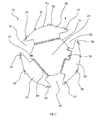
- the Fig. 1 shows a schematic sectional view of a gas stove 1.
- the gas stove 1 is preferably a household appliance.
- the gas stove 1 has a hob 2 with a gas burner 3, a hob cavity 4 and a hob plate 5 on.
- the hob trough 4 may be at least partially made of a metal material.
- the hob cavity 4 is a sheet metal component.
- the hob plate 5 may be formed at least partially of glass ceramic.
- the hob plate 5 may be made at least partially of a metal material.
- the gas burner 3 is arranged in or on the cooktop 2, in particular in or on the cooktop trough 4.
- the gas burner 3 may have a burner head 6, which protrudes upward above the hob plate 5 and a burner housing 7.
- the burner housing 7 is preferably arranged between the hob trough 4 and the hob plate 5.
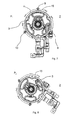
- the burner housing 7 can Positionierfbuse 8 - 10 ( Fig. 7 ) exhibit.
- the burner housing 7 has exactly three positioning feet 8-10, which are distributed over a circumference u 7 of the burner housing 7, in particular distributed uniformly. That is, the positioning feet 8 - 10 are spaced apart at an angular distance of 120 °.
- the Positionierfrissae 8 - 10 extend out of the burner housing 7 down from the burner head 6 away in the direction of the cooktop trough 4.
- the positioning feet 8 - 10 are in particular pen or cylinder-shaped.
- each of the positioning feet 8-10 has a receiving portion 11 which extends into the respective positioning foot 8-10 in the direction of the burner head 6.
- the receiving section 11 may be a bore or recess extending into the respective positioning foot 8-10.
- the cooktop 2 also has a fastening device 12 which is adapted to fix the gas burner 3 on or in the cooktop 2.
- the fastening device 12 may be a burner ring 6 circumferential mounting ring.
- the fastening device 12 may be made at least partially of a metal material.
- the fastening device 12 can act as heat protection for the hob plate 5.
- the hob plate 5 has an opening 13 through which the burner head 6 is guided. With the aid of one and in particular a plurality of fastening elements 14, the fastening device 12 can be connected to the burner housing 7.
- the fastening element 14 may be a screw, for example. Preferably, three fastening elements 14 are provided.
- the hob plate 5 is clamped between the burner housing 7 and the fastening device 12 and the gas burner 3 is at the Hob plate fixed.
- a positioning device 15 is provided for positioning the burner housing 7 relative to the opening 13 of the hob plate 5.
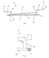
- the Fig. 2 shows a schematic plan view of the positioning 15.
- the Fig. 3 shows a schematic sectional view of the positioning device 15.
- the Fig. 4 shows a schematic detail view of Fig. 3 ,
- the Fig. 5 shows a further schematic sectional view of the positioning device 15.
- the Fig. 6 shows a schematic detail view of Fig. 5 , The following is on the Fig. 2-6 simultaneously referred to.
- the positioning device 15 has a positioning section 16 for selectively positioning the gas burner 3 in different angular positions P 1 , P 2 , P 3 (FIG. Fig. 7 - 9 ) relative to the positioning device 15.
- the positioning portion 16 is plate-shaped and thin-walled.
- the positioning device 15 has a rear engagement portion 17, which is adapted to engage behind a first opening 18 of the hob trough 4.
- the rear engagement portion 17 is preferably hook-shaped.
- the first opening 18 may be a hole provided in the hob trough 4.
- the positioning device 15 has an elastically deformable spring portion 19, which is adapted to engage in a second opening 20 of the hob cavity 4 such that the spring portion 19, the rear gripping portion 17 spring-biased against the first opening 18 of the hob cavity 4.
- the positioning device 15 may further comprise a support portion 21 which is adapted to lie flat on the hob cavity 4.
- the support section 21 is preferably plate-shaped and in particular thin-walled.
- the rear grip section 17 and the spring section 19 preferably extend out of a lower side 22 of the support section 21.
- the rear engagement portion 17 extends initially at an angle of 90 ° out of the support portion 21 to then extend parallel to this extending away from this.
- an angle of 90 ° ⁇ 10 ° preferably of 90 ° ⁇ 5 °, more preferably of 90 ° ⁇ 1 °, more preferably of exactly 90 ° is to be understood here.
- the spring portion 19 extends at an angle ⁇ 1 from the bottom 22 of the support portion 21 out.
- the spring portion 19 is inclined away from the rear grip portion 17.
- the angle ⁇ 1 is preferably greater than 90 °, for example 95 °, 100 °, 105 ° or the like.
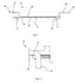
- the rear engagement portion 17 engages behind the hob cavity 4 form fit ( 3 and 4 ).
- the spring portion 19 is pressed into the opening 20 of the hob trough 4, wherein the spring portion 19 rests against an outer edge of the opening 20.
- the support portion 21 may deform.
- the spring portion 19 deforms such that the angle ⁇ 1 is reduced to an angle ⁇ 2 .
- the angle ⁇ 2 is smaller than the angle ⁇ 1 .
- the angle ⁇ 2 can be 90 °. That is, the spring portion 19 is elastically deformed in the direction of the rear grip portion 17. Characterized in that the spring portion 19 is elastically deformed, this biases the rear engagement portion 17 against the first opening 18.
- the support portion 21 is preferably circular.
- the positioning section 16 runs around the support section 21.
- the positioning section 16 is preferably disc-shaped and can rotate the support section 21 in the form of a disk.
- the positioning section 16 may have lateral interruptions 23-25, which are preferably distributed around a circumference u 21 of the support section 21, in particular distributed uniformly.
- the interruptions 23-25 subdivide the positioning section 16 into a plurality, in particular exactly three, sections 26-28.
- the positioning section 16 has for selectively positioning the gas burner 3 in the different angular positions P 1 , P 2 , P 3 relative to the positioning device 15 from the positioning section 16, in particular from the sections 26 - 28, extending anti-rotation elements 29 - 37.
- the anti-rotation elements 29-37 are arranged such that the gas burner 3 can be selectively positioned in exactly three different angular positions P 1 , P 2 , P 3 relative to the positioning device 15.
- Each section of the positioning section 16 preferably has three anti-rotation elements 29 - 37.
- the anti-rotation elements 29 - 37 are spaced from each other, in particular irregularly spaced apart, arranged distributed on a circumference u 16 of the positioning section 16.
- each angular position P 1 , P 2 , P 3 are assigned exactly three anti-rotation elements 29 - 37.
- each angular position P 1 , P 2 , P 3 is associated with a set of anti-rotation elements 29 - 37.
- Each sentence points preferably three anti-rotation elements 29 - 37 on.
- the anti-rotation elements 29 - 37 of a set are preferably distributed uniformly over the circumference u 16 of the positioning section 16.
- an angular distance between the anti-rotation elements 29 - 37 of a set is 120 °.
- the angular spacing of the anti-rotation elements 29 - 37 of a set preferably corresponds to the angular spacing of the positioning feet 8 - 10 of the burner housing 7.
- the anti-rotation elements 29 - 37 preferably extend out of an upper side 38 of the positioning section 16.
- the positioning portion 16 is preferably spaced and arranged parallel to the support portion 21.
- the positioning section is connected to the support section 21 by means of a connecting section 39.
- the anti-rotation elements 29 - 37 are adapted to engage in the respective receiving portions 11 of the positioning feet 8 - 10.
- the positioning device 15 is at least partially made of a metal material.
- the positioning device 15 is formed in one piece material.
- the positioning device 15 may be a Blechstanz- / bent part.
- the Fig. 7 - 9 show the gas burner 3 in the three different angular positions P 1 , P 2 and P 3 .
Landscapes
- Engineering & Computer Science (AREA)
- Chemical & Material Sciences (AREA)
- Combustion & Propulsion (AREA)
- Mechanical Engineering (AREA)
- General Engineering & Computer Science (AREA)
- Baking, Grill, Roasting (AREA)
Applications Claiming Priority (1)
| Application Number | Priority Date | Filing Date | Title |
|---|---|---|---|
| ES201331443A ES2533151B1 (es) | 2013-10-02 | 2013-10-02 | Dispositivo de posicionamiento para posicionar un quemador de gas en o junto a una encimera de cocción, encimera de cocción, y cocina de gas |
Publications (1)
| Publication Number | Publication Date |
|---|---|
| EP2860455A1 true EP2860455A1 (fr) | 2015-04-15 |
Family
ID=51518598
Family Applications (1)
| Application Number | Title | Priority Date | Filing Date |
|---|---|---|---|
| EP20140184034 Withdrawn EP2860455A1 (fr) | 2013-10-02 | 2014-09-09 | Dispositif de positionnement d'un brûleur à gaz dans ou sur une plaque de cuisson, plaque de cuisson et brûleur à gaz |
Country Status (2)
| Country | Link |
|---|---|
| EP (1) | EP2860455A1 (fr) |
| ES (1) | ES2533151B1 (fr) |
Cited By (1)
| Publication number | Priority date | Publication date | Assignee | Title |
|---|---|---|---|---|
| EP3215793A1 (fr) * | 2014-11-06 | 2017-09-13 | BSH Bosch und Siemens Hausgeräte GmbH | Table de cuisson à gaz |
Citations (5)
| Publication number | Priority date | Publication date | Assignee | Title |
|---|---|---|---|---|
| US5266026A (en) * | 1990-10-17 | 1993-11-30 | Robertshaw Controls Company | Burner construction and method of making the same |
| EP0579157A1 (fr) * | 1992-07-13 | 1994-01-19 | Officine Meccaniche Defendi S.R.L: | Brûleur à gaz avec thermocouple de commande |
| US5623917A (en) * | 1995-12-21 | 1997-04-29 | White Consolidated Industries, Inc. | Sealed burner assembly |
| EP2166289A2 (fr) * | 2008-09-22 | 2010-03-24 | BSH Bosch und Siemens Hausgeräte GmbH | Cuisinière à gaz |
| EP2295868A2 (fr) * | 2009-09-09 | 2011-03-16 | BSH Bosch und Siemens Hausgeräte GmbH | Plaque de cuisson à gaz et gazinière dotée d'une plaque de cuisson à gaz correspondante |
Family Cites Families (2)
| Publication number | Priority date | Publication date | Assignee | Title |
|---|---|---|---|---|
| US3015329A (en) * | 1955-02-21 | 1962-01-02 | Chambers Corp | Burner box for top burner unit |
| EP1502055A1 (fr) * | 2002-04-26 | 2005-02-02 | BSH Bosch und Siemens Hausgeräte GmbH | Couvercle de bruleur destine a un bruleur a gaz, bruleur a gaz et plaque de cuisson a gaz |
-
2013
- 2013-10-02 ES ES201331443A patent/ES2533151B1/es not_active Revoked
-
2014
- 2014-09-09 EP EP20140184034 patent/EP2860455A1/fr not_active Withdrawn
Patent Citations (5)
| Publication number | Priority date | Publication date | Assignee | Title |
|---|---|---|---|---|
| US5266026A (en) * | 1990-10-17 | 1993-11-30 | Robertshaw Controls Company | Burner construction and method of making the same |
| EP0579157A1 (fr) * | 1992-07-13 | 1994-01-19 | Officine Meccaniche Defendi S.R.L: | Brûleur à gaz avec thermocouple de commande |
| US5623917A (en) * | 1995-12-21 | 1997-04-29 | White Consolidated Industries, Inc. | Sealed burner assembly |
| EP2166289A2 (fr) * | 2008-09-22 | 2010-03-24 | BSH Bosch und Siemens Hausgeräte GmbH | Cuisinière à gaz |
| EP2295868A2 (fr) * | 2009-09-09 | 2011-03-16 | BSH Bosch und Siemens Hausgeräte GmbH | Plaque de cuisson à gaz et gazinière dotée d'une plaque de cuisson à gaz correspondante |
Cited By (1)
| Publication number | Priority date | Publication date | Assignee | Title |
|---|---|---|---|---|
| EP3215793A1 (fr) * | 2014-11-06 | 2017-09-13 | BSH Bosch und Siemens Hausgeräte GmbH | Table de cuisson à gaz |
Also Published As
| Publication number | Publication date |
|---|---|
| ES2533151A1 (es) | 2015-04-07 |
| ES2533151B1 (es) | 2016-01-22 |
Similar Documents
| Publication | Publication Date | Title |
|---|---|---|
| EP1128432A2 (fr) | Fixation de modules à semi-conducteurs sur un dissipateur de chaleur | |
| EP1651022B1 (fr) | Support pour un composant | |
| EP2099257B1 (fr) | Champ de cuisson | |
| DE3037965A1 (de) | Kochmulde mit glaskeramikplatte | |
| EP2860455A1 (fr) | Dispositif de positionnement d'un brûleur à gaz dans ou sur une plaque de cuisson, plaque de cuisson et brûleur à gaz | |
| DE3637705A1 (de) | Halteklammer fuer mutter mit unterlegscheibe | |
| EP2790468B1 (fr) | Table de cuisson et procédé de montage d'une table de cuisson | |
| DE10306813B4 (de) | Kochfeld | |
| EP3012536B1 (fr) | Plaque de cuisson a gaz | |
| EP0005486B1 (fr) | Table de cuisson avec une plaque de cuisson en vitrocéramique formant la surface de cuisson | |
| EP2175201A2 (fr) | Cuisinière à gaz et support de récipient pour une telle cuisinière à gaz | |
| EP3184911B1 (fr) | Système comprenant une table de cuisson et dispositif de réglage en hauteur | |
| EP1929840B1 (fr) | Dispositif de support pour plaque de cuisson de cuisinière | |
| EP2952817B1 (fr) | Vanne de gaz avec un système de commande d'un appareil ménager et cuisinière | |
| EP3111145B1 (fr) | Appareil électroménager doté d'un élément de fixation | |
| EP3084311B1 (fr) | Plaque de cuisson | |
| EP3018409B1 (fr) | Plaque de cuisson avec une partie inférieure de brûleur à gaz | |
| EP2407675B1 (fr) | Appareil ménager doté d'une plaque de recouvrement et d'un boîtier placé sous la plaque de recouvrement ainsi que procédé de positionnement d'une équerre de fixation sur un boîtier placé sous la plaque de recouvrement d'un appareil ménager | |
| EP0279367A2 (fr) | Appareil pour la cuisson | |
| DE102010063224A1 (de) | Kochfeld mit einer Aufstellplatte und einem Temperatursensor | |
| EP3336440B1 (fr) | Dispositif de fixation de radiateurs plats sur un mur | |
| EP2960581B1 (fr) | Plaque de cuisson | |
| DE102016202768B4 (de) | Kochfeldvorrichtung | |
| DE102005026210A1 (de) | Gaskochfeld | |
| EP3032370A2 (fr) | Systeme d'utilisation d'un appareil menager, vanne de gaz et cuisiniere |
Legal Events
| Date | Code | Title | Description |
|---|---|---|---|
| PUAI | Public reference made under article 153(3) epc to a published international application that has entered the european phase |
Free format text: ORIGINAL CODE: 0009012 |
|
| 17P | Request for examination filed |
Effective date: 20140909 |
|
| AK | Designated contracting states |
Kind code of ref document: A1 Designated state(s): AL AT BE BG CH CY CZ DE DK EE ES FI FR GB GR HR HU IE IS IT LI LT LU LV MC MK MT NL NO PL PT RO RS SE SI SK SM TR |
|
| AX | Request for extension of the european patent |
Extension state: BA ME |
|
| R17P | Request for examination filed (corrected) |
Effective date: 20151015 |
|
| RBV | Designated contracting states (corrected) |
Designated state(s): AL AT BE BG CH CY CZ DE DK EE ES FI FR GB GR HR HU IE IS IT LI LT LU LV MC MK MT NL NO PL PT RO RS SE SI SK SM TR |
|
| GRAP | Despatch of communication of intention to grant a patent |
Free format text: ORIGINAL CODE: EPIDOSNIGR1 |
|
| INTG | Intention to grant announced |
Effective date: 20170105 |
|
| STAA | Information on the status of an ep patent application or granted ep patent |
Free format text: STATUS: THE APPLICATION IS DEEMED TO BE WITHDRAWN |
|
| 18D | Application deemed to be withdrawn |
Effective date: 20170516 |