EP2860606B1 - Informationsverarbeitungsvorrichtung, informationsverarbeitungsverfahren und programm für eine erweiterte realität anzeige - Google Patents
Informationsverarbeitungsvorrichtung, informationsverarbeitungsverfahren und programm für eine erweiterte realität anzeige Download PDFInfo
- Publication number
- EP2860606B1 EP2860606B1 EP13803468.1A EP13803468A EP2860606B1 EP 2860606 B1 EP2860606 B1 EP 2860606B1 EP 13803468 A EP13803468 A EP 13803468A EP 2860606 B1 EP2860606 B1 EP 2860606B1
- Authority
- EP
- European Patent Office
- Prior art keywords
- client
- image
- section
- server
- virtual image
- Prior art date
- Legal status (The legal status is an assumption and is not a legal conclusion. Google has not performed a legal analysis and makes no representation as to the accuracy of the status listed.)
- Not-in-force
Links
Images









Classifications
-
- H—ELECTRICITY
- H04—ELECTRIC COMMUNICATION TECHNIQUE
- H04N—PICTORIAL COMMUNICATION, e.g. TELEVISION
- H04N5/00—Details of television systems
- H04N5/222—Studio circuitry; Studio devices; Studio equipment
- H04N5/262—Studio circuits, e.g. for mixing, switching-over, change of character of image, other special effects ; Cameras specially adapted for the electronic generation of special effects
- H04N5/2621—Cameras specially adapted for the electronic generation of special effects during image pickup, e.g. digital cameras, camcorders, video cameras having integrated special effects capability
-
- G—PHYSICS
- G06—COMPUTING OR CALCULATING; COUNTING
- G06T—IMAGE DATA PROCESSING OR GENERATION, IN GENERAL
- G06T11/00—Two-dimensional [2D] image generation
- G06T11/60—Creating or editing images; Combining images with text
-
- G—PHYSICS
- G06—COMPUTING OR CALCULATING; COUNTING
- G06T—IMAGE DATA PROCESSING OR GENERATION, IN GENERAL
- G06T3/00—Geometric image transformations in the plane of the image
- G06T3/60—Rotation of whole images or parts thereof
-
- G—PHYSICS
- G09—EDUCATION; CRYPTOGRAPHY; DISPLAY; ADVERTISING; SEALS
- G09G—ARRANGEMENTS OR CIRCUITS FOR CONTROL OF INDICATING DEVICES USING STATIC MEANS TO PRESENT VARIABLE INFORMATION
- G09G5/00—Control arrangements or circuits for visual indicators common to cathode-ray tube indicators and other visual indicators
- G09G5/36—Control arrangements or circuits for visual indicators common to cathode-ray tube indicators and other visual indicators characterised by the display of a graphic pattern, e.g. using an all-points-addressable [APA] memory
- G09G5/37—Details of the operation on graphic patterns
- G09G5/377—Details of the operation on graphic patterns for mixing or overlaying two or more graphic patterns
-
- H—ELECTRICITY
- H04—ELECTRIC COMMUNICATION TECHNIQUE
- H04N—PICTORIAL COMMUNICATION, e.g. TELEVISION
- H04N21/00—Selective content distribution, e.g. interactive television or video on demand [VOD]
- H04N21/40—Client devices specifically adapted for the reception of or interaction with content, e.g. set-top-box [STB]; Operations thereof
- H04N21/41—Structure of client; Structure of client peripherals
- H04N21/414—Specialised client platforms, e.g. receiver in car or embedded in a mobile appliance
- H04N21/41407—Specialised client platforms, e.g. receiver in car or embedded in a mobile appliance embedded in a portable device, e.g. video client on a mobile phone, PDA, laptop
-
- H—ELECTRICITY
- H04—ELECTRIC COMMUNICATION TECHNIQUE
- H04N—PICTORIAL COMMUNICATION, e.g. TELEVISION
- H04N21/00—Selective content distribution, e.g. interactive television or video on demand [VOD]
- H04N21/40—Client devices specifically adapted for the reception of or interaction with content, e.g. set-top-box [STB]; Operations thereof
- H04N21/41—Structure of client; Structure of client peripherals
- H04N21/422—Input-only peripherals, i.e. input devices connected to specially adapted client devices, e.g. global positioning system [GPS]
- H04N21/42202—Input-only peripherals, i.e. input devices connected to specially adapted client devices, e.g. global positioning system [GPS] environmental sensors, e.g. for detecting temperature, luminosity, pressure, earthquakes
-
- H—ELECTRICITY
- H04—ELECTRIC COMMUNICATION TECHNIQUE
- H04N—PICTORIAL COMMUNICATION, e.g. TELEVISION
- H04N21/00—Selective content distribution, e.g. interactive television or video on demand [VOD]
- H04N21/40—Client devices specifically adapted for the reception of or interaction with content, e.g. set-top-box [STB]; Operations thereof
- H04N21/41—Structure of client; Structure of client peripherals
- H04N21/422—Input-only peripherals, i.e. input devices connected to specially adapted client devices, e.g. global positioning system [GPS]
- H04N21/4223—Cameras
-
- H—ELECTRICITY
- H04—ELECTRIC COMMUNICATION TECHNIQUE
- H04N—PICTORIAL COMMUNICATION, e.g. TELEVISION
- H04N21/00—Selective content distribution, e.g. interactive television or video on demand [VOD]
- H04N21/40—Client devices specifically adapted for the reception of or interaction with content, e.g. set-top-box [STB]; Operations thereof
- H04N21/43—Processing of content or additional data, e.g. demultiplexing additional data from a digital video stream; Elementary client operations, e.g. monitoring of home network or synchronising decoder's clock; Client middleware
- H04N21/4302—Content synchronisation processes, e.g. decoder synchronisation
- H04N21/4307—Synchronising the rendering of multiple content streams or additional data on devices, e.g. synchronisation of audio on a mobile phone with the video output on the TV screen
- H04N21/43072—Synchronising the rendering of multiple content streams or additional data on devices, e.g. synchronisation of audio on a mobile phone with the video output on the TV screen of multiple content streams on the same device
-
- H—ELECTRICITY
- H04—ELECTRIC COMMUNICATION TECHNIQUE
- H04N—PICTORIAL COMMUNICATION, e.g. TELEVISION
- H04N21/00—Selective content distribution, e.g. interactive television or video on demand [VOD]
- H04N21/60—Network structure or processes for video distribution between server and client or between remote clients; Control signalling between clients, server and network components; Transmission of management data between server and client, e.g. sending from server to client commands for recording incoming content stream; Communication details between server and client
- H04N21/65—Transmission of management data between client and server
- H04N21/658—Transmission by the client directed to the server
- H04N21/6587—Control parameters, e.g. trick play commands, viewpoint selection
-
- H—ELECTRICITY
- H04—ELECTRIC COMMUNICATION TECHNIQUE
- H04N—PICTORIAL COMMUNICATION, e.g. TELEVISION
- H04N23/00—Cameras or camera modules comprising electronic image sensors; Control thereof
- H04N23/60—Control of cameras or camera modules
- H04N23/63—Control of cameras or camera modules by using electronic viewfinders
- H04N23/633—Control of cameras or camera modules by using electronic viewfinders for displaying additional information relating to control or operation of the camera
-
- G—PHYSICS
- G09—EDUCATION; CRYPTOGRAPHY; DISPLAY; ADVERTISING; SEALS
- G09G—ARRANGEMENTS OR CIRCUITS FOR CONTROL OF INDICATING DEVICES USING STATIC MEANS TO PRESENT VARIABLE INFORMATION
- G09G2350/00—Solving problems of bandwidth in display systems
-
- G—PHYSICS
- G09—EDUCATION; CRYPTOGRAPHY; DISPLAY; ADVERTISING; SEALS
- G09G—ARRANGEMENTS OR CIRCUITS FOR CONTROL OF INDICATING DEVICES USING STATIC MEANS TO PRESENT VARIABLE INFORMATION
- G09G2370/00—Aspects of data communication
- G09G2370/02—Networking aspects
- G09G2370/022—Centralised management of display operation, e.g. in a server instead of locally
-
- G—PHYSICS
- G09—EDUCATION; CRYPTOGRAPHY; DISPLAY; ADVERTISING; SEALS
- G09G—ARRANGEMENTS OR CIRCUITS FOR CONTROL OF INDICATING DEVICES USING STATIC MEANS TO PRESENT VARIABLE INFORMATION
- G09G2370/00—Aspects of data communication
- G09G2370/04—Exchange of auxiliary data, i.e. other than image data, between monitor and graphics controller
-
- H—ELECTRICITY
- H04—ELECTRIC COMMUNICATION TECHNIQUE
- H04N—PICTORIAL COMMUNICATION, e.g. TELEVISION
- H04N23/00—Cameras or camera modules comprising electronic image sensors; Control thereof
- H04N23/60—Control of cameras or camera modules
- H04N23/63—Control of cameras or camera modules by using electronic viewfinders
Definitions
- the present disclosure relates to an information processing device, an information processing method, and a program.
- the present disclosure relates to an information processing device, an information processing method, and a program, which perform an augmented reality (AR) display.
- AR augmented reality
- an image in which a virtual image other than a captured image is superimposed on a captured image of a camera, is called an augmented reality (AR) image and has recently been used in various fields.
- AR augmented reality
- portable terminals such as a smartphone having a camera function and a display as well as a communication function
- applications that apply an AR image to such a smartphone are widely used.
- object information is transmitted to a server, and information related to the object is received from the server and is displayed on a display section of the smartphone together with a captured object.
- Image information transmitted from the server to the smartphone is various. For example, there is an image of a virtual character related to a captured object, or a pre-captured person or landscape.
- Patent Literature 1 JP 2012-58838A .
- a user equipment and related method are known, which provide an augmented reality (AR) service including a photographing unit to capture an image of a target object, an information collecting unit to collect contextual information of the captured image of the target object, a tag generating unit to generate an AR tag of a first direction, wherein the AR tag corresponds to the contextual information, and a display unit to display the image of the target object and the AR tag.
- AR augmented reality
- a virtual image to be transmitted from a server is a moving image in which a real person is captured
- the moving image is superimposedly displayed on a captured camera image of a portable terminal of a user
- the captured image and the virtual image show different motions.
- the person as the virtual image is merely stuck on the captured image, and it does not look as if the person exists in the captured image.
- Patent Literature 1 JP 2012-58838A
- the present disclosure has been made in view of, for example, the above problems, and provides an information processing device, an information processing method, and a program.
- the virtual image in a configuration that superimposedly displays a virtual image on a captured image captured by a camera of a portable terminal held by a user and displayed on a display section, the virtual image is changed according to the motion of the camera, so that an AR image can be displayed as if the virtual image exists in the captured image.
- the present invention provides an information processing device in accordance with independent claim 1.
- the present invention provides and information processing device as a server according to independent claim 4.
- the present invention provides an information processing method in accordance with independent claim 6.
- the present invention provides an information processing method in accordance with independent claim 7. Further aspects of the invention are set forth in the dependent claims, the drawings and the following description.
- an information processing device including:
- the information processing device further includes an imaging section configured to capture an image, a display section configured to display a captured image of the imaging section, and a data processing section configured to receive the virtual image from a server and superimposedly display the received virtual image on the captured image displayed on the display section.
- the data processing section estimates the position of the imaging section after predetermined time according to motion information of the information processing device, transmits the estimated position information to the server, receives the virtual image captured from the estimated position or the depth map and the image for virtual image generation from the server, and displays the received image or the image generated based on the received image on the display section.
- the data processing section estimates the capturing direction of the imaging section after time T + ⁇ t considering network delay time ⁇ t that is round trip time of a communication with a server by applying position/orientation information of the imaging section and motion information at current time T, and transmits the estimated direction to the server as the estimated position information.
- the data processing section calculates probability of the capturing direction of the imaging section after time T + ⁇ t considering network delay time ⁇ t that is round trip time of a communication with a server by applying position/orientation information of the imaging section and motion information at current time T, selects an angle range of a range with high probability, and receives, form the server, virtual images of multiple viewpoints included in the selected angle range or the depth map and the image for virtual image generation.
- the data processing section receives, from the server, image data in which an image with a relatively high probability is set as a high-resolution image and an image with a relatively low probability is set as a low-resolution image in the selected angle range.
- the data processing section when there is no great difference in the probability in the selected angle range, the data processing section receives, from the server, the virtual images of the multiple viewpoints included in the selected angle range as images having a same resolution.
- the data processing section selects a virtual image of a viewpoint close to the capturing direction of the imaging section at a display timing of the virtual image from the virtual images of the multiple viewpoints received from the server, or generates a virtual image captured from a viewpoint close to the capturing direction of the imaging section at the display timing of the virtual image by applying the depth map and the image for virtual image generation, and displays the virtual image on the display section.
- an information processing device as a server including:
- the data processing section estimates the capturing direction of the client imaging section after time T + ⁇ t considering network delay time ⁇ t that is round trip time of a communication between the server and the client by applying position/orientation information of the client imaging section and motion information at current time T, and selects the virtual image captured in the estimated direction or the depth map and the image for virtual image generation as data to be transmitted to the client.
- the data processing section calculates probability of the capturing direction of the client imaging section after time T + ⁇ t considering network delay time ⁇ t that is round trip time of a communication between the server and the client by applying position/orientation information of the client imaging section and motion information at current time T, selects an angle range of a range with high probability, and selects the virtual images of the multiple viewpoints included in the selected angle range as data to be transmitted to the client.
- the data processing section generates image data to be transmitted in which an image with a relatively high probability is set as a high-resolution image and an image with a relatively low probability is set as a low-resolution image in the selected angle range, and transmits the image data to the client.
- an information processing device including:
- the storage section stores the depth map and the virtual image corresponding to multiple viewpoints obtained by capturing an object from different multiple viewpoints, and wherein the data processing section generates and displays the virtual image captured from the estimated position on the display section by applying the depth map and the virtual image acquired from the storage section.
- the data processing section calculates probability of the capturing direction of the imaging section after predetermined time according to motion information of the information processing device, selects a virtual image with a high probability from the storage section or generates a virtual image based on the virtual image acquired from the storage section, and displays the virtual image on the display section.
- an information processing method which is performed by an information processing device, wherein the information processing device includes:
- an information processing method which is performed by an information processing device, wherein a data processing section acquires space position information of a terminal including a display section that displays an image in which a virtual image is superimposed on a captured image acquired by an imaging section, and wherein the data processing section specifies display information for displaying the virtual image on the display section according to the space position information of the terminal.
- an information processing method which is performed by an information processing device, wherein the information processing device includes:
- a program for causing an information processing device to execute information processing wherein the information processing device includes:
- a program for causing an information processing device to execute information processing wherein the information processing device includes:
- the program according to the present disclosure is a program that can be provided in a storage medium or communication medium that is provided in a computer-readable form for an information processing device or a computer system that is capable of executing various types of program code, for example. Providing this sort of program in a computer-readable form makes it possible to implement the processing according to the program in the information processing device or the computer system.
- the virtual image which is natural according to the capturing direction of the camera, can be superimposedly displayed on the captured camera image displayed on the display section.
- the configuration includes the server that transmits the virtual image to the client, and the client that superimposedly displays the captured camera image and the virtual image transmitted from the server.
- the server transmits, to the client, the virtual image captured from the client position after a predetermined time estimated according to the motion of the client (camera).
- the server and the client by applying the client position and orientation information at the current time T and the motion information, the capturing direction of the client after the time T + ⁇ t considering the network delay time ⁇ t that is the round trip time of communication between the server and the client is estimated, and the virtual image captured in the estimated direction is transmitted to the client.
- the virtual image which is natural according to the capturing direction of the camera, can be superimposedly displayed on the captured camera image displayed on the display section of the client.
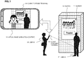
- FIG. 1 is a diagram illustrating an example of use of processing of the present disclosure.
- a user A 21 stands in front of a poster 10, and a user B 22 captures an image, including the poster 10 and the user A 21, by using a portable terminal (client) 30 such as a smartphone with a camera function.
- the captured image is, for example, a moving image.
- the portable terminal (client) 30 transmits capturing information to a server through a communication section of the client (portable terminal) 30.
- the server recognizes that the client (portable terminal) 30 captures the image including the poster 10, based on the capturing information received from the client (portable terminal) 30, acquires content stored in a content database inside the server, for example, a moving image content generated by capturing a person printed on the poster 10, and transmits the acquired content to the portable terminal (client) 30.
- the portable terminal (client) 30 superimposedly displays the content (moving image) received from the server on the image being captured.
- a virtual image (live-action image) 31 is an image displayed on the client (portable terminal) 30.
- the portable terminal (client) 30 displays an augmented reality (AR) image in which the captured image actually captured by the portable terminal (client) 30 is displayed together with the virtual image received from the server.
- AR augmented reality
- the virtual image 31 displayed on the portable terminal (client) 30 is an image of a person who does not exist at a place where the user A and the user B are located.
- the image is displayed as if the person stands next to the user A 21.
- the client (portable terminal) 30 can capture and record the captured image, including the virtual image 31, as a moving image or a still image.
- the user B 22 who performs capture processing by using the portable terminal (client) 30 captures an image while moving the portable terminal (client) 30. At this time, a capturing direction is changed and the image is changed according to a change in the capturing direction.
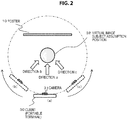
- a position of a camera 31 provided in the portable terminal (client) 30 is changed to various positions, such as (a), (b), and (c), by the user.
- the capturing direction of the camera 31 is variously set to, for example, (direction a), (direction b), and (direction c).
- the virtual image 31 In order to display the image as if the subject person of the virtual image 31 displayed on the portable terminal (client) 30 exists at that capturing spot, the virtual image 31 needs to be changed to an image corresponding to each capturing direction, that is, (direction a), (direction b), and (direction c).
- the virtual image 31 displayed on the portable terminal (client) 30 is changed according to the motion of the portable terminal (client) 30 and is set as if the person as the virtual image displayed on the portable terminal (client) 30 exists at that place.
- FIG. 3 illustrates ideal display image examples of the virtual image corresponding to the following five capturing directions.
- FIG. 3(a) is a capturing state from a front side of the virtual image subject assumption position 32.
- FIG. 3(R1) is a capturing state from a right oblique direction of the virtual image subject assumption position 32.
- FIG. 3(R2) is a capturing state from a right direction of the virtual image subject assumption position 32.
- FIG. 3(L1) is a capturing state from a left oblique direction of the virtual image subject assumption position 32.
- FIG. 3(L2) is a capturing state from a left direction of the virtual image subject assumption position 32.
- the virtual image corresponding to the motion of the portable terminal is displayed on a display section of the client (portable terminal) 30, and a moving image can be viewed as if the person corresponding to the virtual image exists at that place and can be captured and recorded.
- the client that performs the image capture and display is not limited to the smartphone illustrated in FIG. 1 and can be realized by various information processing devices, for example, a PC or a glass-type AR glass.
- the virtual image can be changed according to the change in the image to be superimposed, when the virtual image such as a person is superimposedly displayed on the image being displayed on the client such as the smartphone or the AR glass, and the virtual image can be displayed as if it exists in a base image to be superimposed.
- free-viewpoint live-action moving image content observed from various viewpoints is transmitted from the server to the client and is superimposedly displayed on a captured camera image displayed on the display section of the client.
- a virtual image with a natural motion corresponding to the motion of the client (camera) is realized.
- the server delivers moving image content captured from a plurality of different viewpoints to the client.
- the client selects display content from the received moving image content of each viewpoint according to capturing angle information of the imaging section (camera) of the client, and performs decoding and display processing on the selected moving image content.
- the server delivers moving image content from discontinuous, that is, discrete different viewpoints.
- embodiment 2 is an embodiment that also provides depth information (depth map) according to the moving content to be provided to the client.
- the depth map is configured by data in which distance information from the camera to the subject is set by a pixel unit.
- the moving image content from discontinuous different viewpoints is used to generate necessary display content, that is, a virtual image observed from a desired direction.
- necessary display content that is, a virtual image observed from a desired direction.
- an image of a middle viewpoint of the directions A and B is generated and displayed by using the real-action images of the direction A and the direction B and the depth map corresponding to each image.
- transmission data to be transmitted from the server to the client can be reduced. It is only necessary to transmit the images of at least two viewpoints (three or more viewpoints according to an angle or a position).
- the client in ether of embodiments 1 and 2, the client superimposes the virtual image, which is generated or selected according to the position/angle of the camera provided in the client, on the captured camera image that is the base image being displayed in the client.
- the virtual image, which is provided by the server and is to be superimposed on the client is, for example, a live-action person image
- the permeability of pixel portions other than the person is maximized and the virtual image is moving image content with ⁇ channel information of pixel unit, called permeability information or mask information such as setting the permeability of a person region to 0.
- a network delay occurs in communication between the server and the client. Therefore, the content provided from the server to the client needs to be content in which the network delay is considered. That is, for example, the capturing angle of the client after a predetermined time is predicted based on the motion of the client, and the moving image content from a viewpoint within a predetermined range, with the predicted angle as a center, is adaptively delivered.
- the processing of the present disclosure can realize, for example, real-time rendering of the virtual image corresponding to the motion of the client, which has been described with reference to FIG. 3 .
- the motion prediction of the client can be performed as, for example, the processing using the marker included in the captured image of the client. That is, camera position information or camera moving direction, and camera moving speed are acquired from the capturing position of the marker, the motion of the client is predicted from such information, and the camera position and orientation after a predetermined time are estimated. Also, it may be configured to use sensor information of acceleration/gyro sensors provided in the client.
- the processing of the present disclosure generates and displays the AR image in which the virtual image is superimposed together with the captured image on the display section of the client.
- the virtual image is provided from the server to the client.
- the virtual image can be acquired from the storage section of the client, without being provided from the server.
- step S11 a client 100, which performs an image capture, transmits capturing information to a server.
- the capturing information may be, for example, information that can confirm that the poster 10 illustrated in FIG. 1 is captured, and may be identification information such as a poster image or a two-dimensional bar code such as a cyber-code set to in the poster 10.
- the server 200 acquires moving image content, which is to be provided to the client based on the capturing information, from a database, and transmits the acquired moving image content.
- the server selects and transmits an image of a viewpoint determined according to the motion of the client 100, that is, a virtual image observed from a direction estimated as a direction in which the client captures an image after a predetermined time. Details of the moving image content transmission will be described below.
- step S13 the client 100 superimposedly displays the moving image content received from the server 200 on the captured image.
- the flow illustrated in FIG. 5 is a flow including the processing of the client that performs the processing of displaying the AR image in which the virtual image is superimposed on the captured image, and the processing of the server that provides the virtual image.
- steps S101 to S105 is processing that is performed by the client
- the processing of steps S106 and S107 is processing that is performed by one of the server and the client
- the processing of step S108 is processing that is performed by the server
- the processing of steps S109 to S114 is processing that is performed by the client.
- the processing illustrated in the flow is performed under the control of a data processing section of the server or the client, that is, a data processing section having a CPU or the like with a program execution function, according to a program stored in, for example, a storage section of the server or the client.
- step S101 the client captures an image.
- the poster as illustrated in FIG. 1 is captured.
- step S102 the client determines whether information acquisition for calculating position and angle information of the camera, which is necessary at a latter stage, is successful.
- An example of the information for calculating the position and angle information of the camera is a marker included in the captured image.
- the marker is a two-dimensional bar code such as, for example, a cyber-code printed in advance on the poster 10 illustrated in FIG. 1 .
- the position or the angle of the camera can be calculated from an angle of a marker reflected on a camera image.
- the information for calculating the position and angle information of the camera is not limited to the marker such as the cyber-code, and may be an object itself such as a poster or a CD jacket.
- What is used as the information for calculating the position and angle information of the camera is different according to the camera position and angle calculation processing algorithm performed by the client, and the application information can be variously set.
- position identification processing to which a simultaneous localization and mapping (SLAM) technology is applied may be performed.
- SLAM simultaneous localization and mapping
- information of a sensor included in the client device may be applied.
- step S102 it is determined whether the acquisition of the camera position and angle information, which is performed by the client, is successful.
- step S103 the client calculates a current position and orientation of the client (camera) by applying the information acquired in step S102.
- step S104 the client acquires output values of an acceleration sensor and a gyro sensor provided in the client.
- step S105 the client calculates a moving speed and a moving direction of the client (camera).
- This processing is performed by applying, for example, the current position and orientation of the client (camera), which is calculated in step S103, and the sensor information, which is acquired in step S104.
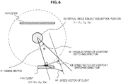
- step S105 A specific processing example of step S105 will be described with reference to FIG. 6 .
- FIG. 6 illustrates the client 100 that displays the captured image and the AR image, and the virtual image subject assumption position 32.
- the client 100 can be freely moved by the user.
- step S104 a speed vector V1 of the client is calculated.
- the virtual image subject assumption position T (tx, ty, tz).
- step S105 The purpose of the processing of step S105 is to calculate an angular speed ⁇ illustrated in FIG. 6 , that is, an angular speed ⁇ of a viewpoint switching direction with respect to the virtual image subject.
- the angular speed ⁇ illustrated in FIG. 6 is an angular speed corresponding to the motion of the client 100 at the current time.
- a speed vector v2 of the client 100 in a direction perpendicular to the radius vector r is calculated based on the speed vector v1.
- the speed vector v2 is a speed vector in the viewpoint switching direction corresponding to the virtual image subject.
- the angular speed ⁇ in the viewpoint switching direction corresponding to the virtual image subject can be calculated by the following formula, based on the radius vector r and the speed vector v2 of the client in the direction perpendicular to the radius vector r.
- ⁇
- the angular speed ⁇ in the viewpoint switching direction corresponding to the virtual image subject is calculated based on the above formula.
- steps S106 and S107 is processing that is performed by one of the client and the server.
- step S106 for example, a ping command is transmitted and received between the client and the server, and a round trip time (RTT) is calculated.
- RTT round trip time
- the capturing angle of the client (camera) after the predetermined time is estimated based on the moving direction and speed of the client (camera) obtained in step S105 and the network delay time obtained in step S106, an angle range of the virtual image content to be transmitted to the client is set, and the transmission image is determined.
- step S107 Details of the processing of step S107 will be described with reference to FIG. 7 and thereafter.
- step S107 is performed by processing of steps S201 to S203 of a flow illustrated in FIG. 7 .
- the center viewpoint of the client (camera) after a network delay time ⁇ t is calculated.
- the current time is T
- the network delay time is ⁇ t
- the camera viewpoint of the client at the current time T is ⁇ T
- the angular speed in the viewpoint switching direction of the client at the current time T is ⁇ T .
- the network delay time ⁇ t is a round trip time (latency) from the client to the server.
- data required to be transmitted to the client by the server is a virtual image that is observed from an estimated position of the client after the network delay time ⁇ t from the current time T, that is, at the time T + ⁇ t.
- the server transmits a plurality of virtual image contents that is captured from a viewpoint that is not in a predetermined angle range, with the client viewpoint ⁇ T + ⁇ t at the time T + ⁇ t as a center.
- the client selects the image corresponding to the actual position of the client from the plurality of images and displays the selected image.
- the motion of the client is predicted, and the image of the viewpoint corresponding to the predicted position of the client is selected and provided from the server to the client.
- This processing reduces an amount of transmission data, reduces the processing load of the client side, and realizes the display of the AR image efficiently and with highly accurately.
- step S201 the client viewpoint ⁇ T + ⁇ t at the time T + ⁇ t is calculated based on the above formula. That is, the center viewpoint of the client (camera) after the network delay time ⁇ t is calculated.
- the client viewpoint ⁇ T + ⁇ t at the time T + ⁇ t may be calculated considering an angular acceleration of the client and an angular speed at the time T + ⁇ t.
- a viewpoint range of the image to be transmitted from the server to the client is determined.
- the client viewpoint ⁇ T + ⁇ t obtained in step S201 is one viewpoint corresponding to the position of the client after ⁇ t from the current time T, which is estimated under the assumption of the data acquired at the time T.
- the user does not necessarily move the client according to the assumption of the data acquired at the time T, and the moving speed or direction of the client (camera) can be sequentially changed.
- the network delay time is inconstantly changed by a communication state of the network.
- the client viewpoint ⁇ T + ⁇ t obtained in step S201 is not unnecessarily matched to the actual client viewpoint at the time T + ⁇ t and is merely one viewpoint position predicted to occur with high probability.
- the server transmits only one virtual image content corresponding to the client viewpoint ⁇ T + ⁇ t to the client, when the actual client viewpoint is matched with the viewpoint ⁇ T + ⁇ t , it is only necessary to display the transmission image, but an erroneous image is displayed if the actual client viewpoint is deviated.
- the server transmits an image of a viewpoint around that viewpoint to the client, as well as the virtual image corresponding to the client viewpoint ⁇ T + ⁇ t estimated in step S201.
- step S202 a viewpoint range corresponding to a plurality of image contents of different viewpoints to be transmitted to the client is determined.
- the following processing can be performed: the angular speed ⁇ T + ⁇ t of the client at the time T + ⁇ t is predicted at the timepoint of the current time T, a log of a difference ratio of the predicted angular speed to the actual angular speed ⁇ T + ⁇ t of the client at the time T + ⁇ t is collected, and ⁇ 2 ⁇ of the standard deviation of the error ratio is set to an angle range to be transmitted.
- an angle range ⁇ n degrees may be set in advance, and an image of a range of client viewpoint ⁇ T + ⁇ t ⁇ n degrees estimated in step S201 may be set as the transmission image.
- the image of the range of client viewpoint ⁇ T + ⁇ t ⁇ n degrees may be set as the transmission image
- a function f( ⁇ T , ⁇ t) having values of the client angular speed ⁇ T of the time T and the network delay time ⁇ t as parameters may be set, and the angle range of the transmission image can be determined by the setting of gradually increasing the angle range if the function f( ⁇ T , ⁇ t) exceeds a preset threshold value.
- step S202 for example, the moving image content of the following multiple viewpoints are determined as the content to be transmitted to the client.
- step S202 the moving images of the multiple viewpoints within the predetermined range including the client viewpoint ⁇ T + ⁇ t estimated in step S201 are determined as the images to be transmitted to the client.
- the determined moving images are the above moving image contents (1) to (5).
- the viewpoint positions of the plurality of moving image contents are viewpoint positions determined based on the motion prediction of the client (camera), and it is estimated that the probability that the client (camera) will be set to the viewpoints corresponding to the above images (1) to (5) is different.
- the client viewpoint ⁇ T + ⁇ t estimated in step S201 is a viewpoint at which it is estimated that it will occur with the highest probability as the viewpoint of the client at the time T + ⁇ t, and it is estimated that the occurrence probability will be reduced as the distance from that viewpoint is increased.
- the image contents of the multiple viewpoints included in the viewpoint range set in step S202 are transmitted as the following setting.
- the image of the viewpoint estimated to be high probability as the viewpoint of the client at the time T + ⁇ t is transmitted as a high-resolution image
- the image in the range estimated to be low probability is transmitted as a low-resolution image.
- step S203 in order to enable the image transmission in such a setting, the probability that the client (camera) will be set to each viewpoint position included in the viewpoint range set in step S202 is estimated.
- a normal distribution is set such that the client viewpoint ⁇ T + ⁇ t at the time T + ⁇ t calculated in step S201 has the maximum probability, and the probability that the client (camera) will be set to each viewpoint position is estimated by applying a probability density function according to the normal distribution.
- FIG. 8 illustrates the normal distribution in which the client viewpoint ⁇ T + ⁇ t at the time T + ⁇ t calculated in step S201 has the maximum probability.
- a horizontal axis represents the viewpoint and a vertical axis represents the occurrence probability.
- the center (0) of the viewpoint axis corresponds to the client viewpoint ⁇ T + ⁇ t at the time T + ⁇ t calculated in step S201.
- the client angular speed of the time T is ⁇ T
- the network delay time is ⁇ t
- ⁇ is a preset coefficient and ⁇ is a preset positive integer.
- the occurrence probability of the client viewpoint ⁇ T + ⁇ t at the time T + ⁇ t calculated in step S201 is higher as compared with the occurrence probability of the surrounding viewpoints.
- the probability that the client (camera) will be set to each viewpoint position included in the viewpoint range set in step S202 is estimated.
- the center (0) of the viewpoint axis is set to the client viewpoint ⁇ T + ⁇ t at the time T + ⁇ t calculated in step S201.
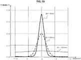
- the probability density function indicating the occurrence probability corresponding to each angle when the center (0) of the viewpoint axis is set to the actual client viewpoint ⁇ T at the time T is set as illustrated in FIG. 9 .
- ⁇ 0deg/s
- ⁇ - 2deg/s
- ⁇ + 2deg/s
- ⁇ - 10deg/s
- ⁇ + 10deg/s
- the probability density function illustrated in FIG. 9 indicates the probability of the client position estimated when the center (0) of the viewpoint axis is set to the actual client viewpoint ⁇ T at the time T and is located at the position after the time ⁇ t with respect to the angular speed ⁇ of the client (camera).
- the occurrence probability of the client viewpoint ⁇ T + ⁇ t at the time T + ⁇ t calculated in step S201 is higher as compared with the occurrence probability of the surrounding viewpoints.
- the network delay time ⁇ t has only to generate the normal distribution data illustrated in FIG. 8 by applying the value acquired at the time T.
- the network delay time ⁇ t is measured by the one-time transmission and reception of the ping data, the accurate delay time is not always measured. Considering this, a fluctuation compensation of the delay time may be performed.
- FIG. 11 illustrates the fluctuation compensation graph of the delay time.
- a horizontal axis represents a viewpoint axis in which the client viewpoint ⁇ T + ⁇ t at the time T + ⁇ t calculated in step S201 is set as the center (0), and a vertical axis represents the occurrence probability.
- the delay time standard deviation is set as ⁇ t and the fluctuation compensation angle range is set as ⁇ t .
- ⁇ is a preset coefficient
- NORMDIST(x, u, ⁇ ) is a probability density function of x at a century distribution of average u and standard deviation ⁇ .
- the graph of FIG. 11 indicates the probability density function.
- the fluctuation compensation may be performed by applying the fluctuation compensation graph of the delay time illustrated in FIG. 11 to the network delay time ⁇ t acquired based on the transmission and reception of the ping command at the time T, and the normal distribution data illustrated in FIG. 8 may be generated by reflecting the result.
- step S203 of the flow illustrated in FIG. 7 by performing the above processing, the probability density function made up of the normal distribution data illustrated in FIG. 8 is set by applying the respective data measured at the time T, or correction data, for example, and the probability that the client (camera) will be set to each viewpoint position included in the viewpoint range set in step S202 is estimated according to the probability density function.
- step S107 of the flow illustrated in FIG. 5 the processing of selecting the transmission image is performed based on the estimation of the camera angle according to the flow illustrated in FIG. 7 , and the probability that the client will be set to each viewpoint of the each selected image is calculated.
- the transmission image data is determined as illustrated in FIG. 12 , and the probability of each determined transmission image, that is, the probability that the client will be set to the position of the image of that viewpoint is calculated.
- the data illustrated in FIG. 12 is an example of data set in step S107.
- step S107 for example, as illustrated in FIG. 12 , the following data (1) to (5) are determined as the transmission images, and the probability of each image is calculated.
- step S107 for example, the probability of determining and generating such transmission images is determined.
- step S108 of the flowchart illustrated in FIG. 5 will be described.
- step S108 is processing that is performed by the server.
- the server generates a stream to be transmitted to the client by using the data determined in the processing of step S107, that is, for example, the probability data and the images to be transmitted to the client as illustrated in FIG. 12 .
- a stream generation example is illustrated in FIG. 13 .
- the server generates a stream including a plurality of moving image contents illustrated in FIG. 13(A) and transmits the stream to the client.
- FIG. 13(B) is a graph of the probability density function described above with reference to FIG. 8 and illustrates the probability of the client (camera) set to each angle, with the estimated angle at the time T + ⁇ t of the client (camera) as the center (0) of a horizontal axis.
- This probability corresponds to the probability of the data illustrated in FIG. 12 .
- the server generates stream data of multiple images in which the image of the viewpoint with high probability is configured as the high-resolution image (high-bit-rate image) and the image of the viewpoint with low probability is configured as the low-resolution image (low-bit-rate image), as the image 1 (View 1), the image 2 (View 2), the image 3 (View 3), ..., the image 7 (View 7) in descending order of probability, and transmits the stream data to the client.
- FIG. 13(A) is a setting example of the transmission image stream when the probability distribution illustrated in FIG. 13(B) is acquired.
- the image stream data in which images of different viewpoints are all set as the data of the same resolution may be generated and transmitted as illustrated in FIG. 14(A) .
- each viewpoint may be transmitted as a separate stream, but it may be set such that multiple images of multiple viewpoints are packed into one stream and then transmitted.
- the image stream of each viewpoint is generated in advance for each resolution and bit rate and is stored in a database, instead of real-time encoding.
- the image data to be transmitted from the server to the client is data that is encoded by, for example, a predetermined encoding algorithm such as MPEG, and it is necessary to perform decoding processing on the client side.
- a predetermined encoding algorithm such as MPEG
- the image stream to be provided to the client is set to two types of image streams: (a) moving image sequence in which all frames are key frames, and (b) general moving image sequence.
- the moving image sequence in which all frames are key frames is, for example, encoded data that are configured by image frames capable of decoding each image frame by itself.
- the general moving image sequence is, for example, encoded data that need to be decoded with reference to the previous or next image frame.
- the client can first read the first frame from the "moving image sequence in which all frames are key frames" at the time of switching the stream, perform fast decoding processing to display the first frame on the display section and continue the display by reading the second and subsequent frames from the "general moving image sequence” and decoding the second and subsequent frames.
- the delay at the time of display switching can be reduced.
- the stream to deliver the image of the maximum probability is set as a fixed stream, and partial real-time encoding is performed to deliver contents of different viewpoints changed according to the motion of the client by using the same fixed stream.
- the client receives the image stream of the virtual image in step S109.
- the image stream is a stream made up of moving image data of the images of multiple viewpoints described with reference to FIG. 13(A) or 14(A) .
- the client calculates the camera position and angle upon reception of the stream, selects the virtual image to be displayed on the display section of the client, and determines the superimposition position of the selected virtual image.
- the processing of calculating the camera position and angle is the same processing of steps S102 and S103 as described above and determines the processing of selecting the virtual image and the superimposition position by applying the calculation result.
- step S111 the client performs the decoding processing on the virtual image stream selected as the image to be displayed.
- step S112 the client superimposes the decoded content on the captured camera image being displayed on the display section of the client.
- step S113 the client outputs an AR image in which the virtual image is superimposed on the captured image as the final result on the display section (display) of the client.
- step S114 it is determined whether a predetermined finish condition, such as the finish of the image capture processing or the finish of the application, occurs, and non-processing is ended when the finish condition occurs. When the finish condition does not occur, the processing returns to step S101 and the same processing is repeated.
- a predetermined finish condition such as the finish of the image capture processing or the finish of the application
- the virtual image transmitted from the server is superimposedly displayed on the captured image that is displayed on the display section of the client.
- the processing of steps S105 to S107 is omitted, and, after the acquisition of the camera position/orientation information in step S103 and the calculation of the moving direction and speed of the camera in step S104, the virtual image to be displayed on the display section is generated or selected and then output to the display section, based on such acquired information, that is, space position information such as the position, orientation, or motion of the camera.
- FIG. 15 illustrates a configuration example of the server 200 and the client 100 that perform the present embodiment 1.
- Data transmission and reception is performed between a communication section 108 of the client 100 and a communication section 207 of the server 200.
- a network delay estimation section 106 and an angle range estimation section 107 which are illustrated in the configuration of the client 100, may be set as elements of the server 200, instead of the client 100.
- the client 100 and the server 200 which are illustrated in FIG. 15 , perform the above-described processing according to the flow illustrated above in FIG. 5 .
- An imaging section (camera) 101 of the client 100 performs the camera image acquisition processing of step S101 of the flow illustrated in FIG. 5 .
- An image recognition section 102 performs the camera position/orientation calculation information acquisition processing of step S102 of the flow of FIG. 5 . Specifically, for example, the processing of recognizing the marker set to the subject such as the poster illustrated in FIG. 1 is performed.
- a client (camera) position/orientation calculation section 103 performs the camera position/orientation calculation processing of step S103 of the flow of FIG. 5 .
- a sensor (acceleration/gyro sensor, etc.) 104 performs thee sensor information acquisition processing of step S104 of the flow of FIG. 5 .
- a client moving speed/direction calculation section 105 performs the client (camera) moving speed/direction calculation processing of step S105 of the flow of FIG. 5 .
- a network delay estimation section 106 performs the network delay estimation processing of step S106 of the flow of FIG. 5 .
- An angle range estimation section 107 performs the processing of step S107 of the flow of FIG. 5 , that is, the transmission image determination processing and the probability estimation processing, based on the client (camera) position estimation.
- the network delay estimation section 106 and the angle range estimation section 107 may be set to the server 200 side and performed as the processing of the server 200.
- the angle range estimation section 107 determines the transmission image based on the client (camera) position estimation and calculates the probability corresponding to each transmission image, that is, the probability that the client will be set to the viewpoint position corresponding to each image. Specifically, for example, the data described above with reference to FIG. 12 is generated.
- the data is input to a transmission image data generation section 206 of the server 200 through a communication section.
- the server 200 previously generates the image content (moving image stream) of multiple viewpoints to be provided to the client, and holds the image content as the content 205 corresponding to each viewpoint.
- the server generates the content 205 corresponding to each viewpoint by performing the following processing as pre-processing.
- a depth information (depth map) generation section 202 acquires content stored in a content database 201, that is, image content of discrete multiple viewpoints, and generates depth information (depth map) 203 corresponding to the image.
- a middle viewpoint image generation section 204 generates image content of a middle viewpoint, which is not included in the content stored in the content database 201, by applying the content stored in the content database 201 and the depth information (depth map) 203,
- the server 200 previously generates the image of each viewpoint of 360 degrees with respect to a certain subject, which includes the content stored in the content database 201 and the image content of the middle viewpoint that is not included in the content stored in the content database 201, as the content 205 corresponding to each viewpoint.
- the transmission image data generation section 206 of the server 200 performs the processing of generating the transmission stream from the content 205 corresponding to each viewpoint to the client, based on the image content to be transmitted to the client. That is, the process of step S108 of the flow illustrated in FIG. 5 is performed.
- the server generates the stream to be transmitted to the client by using the probability data and the images to be transmitted to the client as illustrated in FIG. 12 .
- the stream is combined data of the image contents of the multiple viewpoints as illustrated in FIGS. 13(A) and 14(A) .
- the transmission data generated by the transmission image data generation section 206 is transmitted to the communication section 108 of the client 100 through the communication section 207.
- the communication section 108 of the client 100 performs the virtual image stream reception processing of step S109 of the flow of FIG. 5 .
- a content selection and superimposition position calculation section 109 of the client 100 performs the processing of step S110 of the flow of FIG. 5 , that is, the processing of selecting the virtual image and determining the superimposition position. That is, the camera position and angle are calculated upon reception of the stream, the virtual image to be displayed on the display section of the client is selected, and the superimposition position of the selected virtual image is determined.
- a decoding section 110 performs the processing of step S111 of the flow of FIG. 5 , that is, the processing of decoding the selected virtual image stream.
- a display control section 111 performs the processing of steps S112 and S113 of the flow of FIG. 5 , that is, outputs an AR image in which the decoded content is superimposed on the captured camera image that is displayed on the display section 112 of the client 100.
- the virtual image transmitted from the server is superimposedly displayed on the captured image that is displayed on the display section of the client.
- the configuration illustrated in FIG. 15 is a diagram illustrating the main configuration of the server and the client.
- the server and the client include, for example, the control section having the CPU or the like that controls the processing described with reference to FIG. 6 , or the storage section that stores the program to be performed by the control section.
- the second embodiment is an embodiment in which contents of discrete multiple viewpoints and depth information (depth map) corresponding to the contents are transmitted from the server to the client, and the image of an arbitrary viewpoint to be displayed on the client is generated on the client side.
- the server transmits the depth map and the image for the virtual image generation for the purpose of generating the virtual image to be displayed to the client.
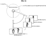
- the moving image content of a viewpoint of a certain angle range for example, n moving image contents from the moving image 1 to the moving image n as illustrated in FIG. 16 , are transmitted to the client, and the client performs the processing of selecting the content suitable for the angle or the like of the client from the n contents and displaying the selected content.
- the images of several discrete viewpoints for example, the moving images of only three viewpoints as described in FIG. 17 among the moving image contents of the multiple viewpoints of a certain angle range, are transmitted to the client. Furthermore, depth information (depth map) corresponding to the three moving images to be transmitted is also transmitted to the client.
- the client generates the image of the middle viewpoint from the viewpoint between the moving image 1 and the moving image 2 by applying the images of discrete viewpoints and the depth map, and generates and displays the image to be displayed on the client.
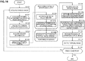
- the flow illustrated in FIG. 18 includes the processing common to the flow of FIG. 5 described above as the processing sequence of the first embodiment.
- step S107b, step S108b, step S110b, and step S111b which are illustrated in the flow of FIG. 18 , is different from the processing of embodiment 1.
- the flow illustrated in FIG. 18 is a flow including the processing of the client that performs the processing of displaying the AR image in which the virtual image is superimposed on the captured image, and the processing of the server that provides the virtual image.
- steps S101 to S105 is process that is performed by the client
- the processing of steps S106 and S107 is process that is performed by one of the server and the client
- the processing of step S108 is process that is performed by the server
- the processing of steps S109 to S114 is process that is performed by the client.
- the processing illustrated in the flow is performed under the control of the data processing section of the server or the client, that is, the data processing section having a CPU or the like with the program execution function, according to the program stored in, for example, the storage section of the server or the client.
- step S101 the client captures an image.
- the poster as illustrated in FIG. 1 is captured.
- step S102 the client determines whether information acquisition for calculating position and angle information of the camera, which is necessary at a later stage, is successful.
- An example of the information for calculating the position and angle information of the camera is a marker included in the captured image.
- the marker is a two-dimensional bar code such as, for example, a cyber-code printed in advance on the poster 10 illustrated in FIG. 1 .
- step S103 the client calculates a current position and orientation of the client (camera) by applying the information acquired in step S102.
- step S104 the client acquires output values of an acceleration sensor and a gyro sensor provided in the client.
- step S105 the client calculates a moving speed and a moving direction of the client (camera).
- This processing is performed by applying, for example, the current position and orientation of the client (camera), which is calculated in step S103, and the sensor information, which is acquired in step S104.
- step S105 A specific processing example of step S105 is the same as described above with reference to FIG. 6 .
- steps S106 and S107b is process that is performed by one of the client and the server.
- step S106 for example, a ping command is transmitted and received between the client and the server, and a round trip time (RTT) is calculated.
- RTT round trip time
- the capturing angle of the client (camera) after a predetermined time is estimated based on the moving direction and speed of the client (camera) calculated in step S105 and the network delay time calculated in step S106, an angle range of the virtual image content to be transmitted to the client is set, and the transmission image is determined.
- step S107b is performed by processing of steps S201 to S203 of the flow illustrated in FIG. 7 .
- the image of the viewpoint of the angle range to be transmitted and that probability, which are illustrated in FIG. 12 , that is, the probability that the client will be set to the position of the image of that viewpoint, are calculated.
- the server generates the image data stream in which the transmission image data determined in the processing of step S107b and the depth map are combined.
- a stream generation example will be described with reference to FIG. 19 and thereafter.
- FIG. 19(A) is probability distribution data corresponding to the viewpoint calculated according to the flow illustrated in FIG. 7 .
- the image of the discrete viewpoint to be transmitted to the client is selected and transmitted to the client.
- FIG. 19(B) is an example of the transmission image data.
- View 1 being the image of the viewpoint at the time T + ⁇ t
- View 2 and (View 3) being the images of the viewpoints at the positions spaced a predetermined angle apart are transmitted as high-resolution images.
- the images (View 4) to (View 7) corresponding to the angles of the viewpoints spaced apart from (View 1) being the image of the viewpoint at the time T + ⁇ t are transmitted as low-resolution images.
- depth information (depth map) corresponding to the respective images is also transmitted to the client.
- the server selects the image of the middle viewpoint between (View 1) and (View 2) as the display image
- the client generates and displays the image of the middle viewpoint by using the images of the (View 1) and (View 2) and the depth map of each image.
- the example illustrated in FIG. 20 is also a processing example in which the transmission image is reduced.
- FIG. 20(A) is probability distribution data corresponding to the viewpoint calculated according to the flow illustrated in FIG. 7 .
- the image of the discrete viewpoint to be transmitted to the client is selected and transmitted to the client.
- FIG. 20(B) is an example of the transmission image data.
- (View 1) being the image of the viewpoint at the time T + ⁇ t
- (View 2) and (View 3) being the images of the viewpoints at the positions spaced a predetermined angle apart are transmitted as high-resolution images.
- the server selects the image of the middle viewpoint between (View 2) and (View 6) as the display image
- the client When the server selects the image of the middle viewpoint between (View 2) and (View 6) as the display image, the client generates and displays the image of the middle viewpoint by using the images of the (View 2) and (View 6) and the depth map of each image.
- step S108b of the flow of FIG. 18 the transmission image stream is generated in such various settings and is transmitted to the client.
- the image of the discrete viewpoint is selected and transmitted together with the depth map, and the image of the middle viewpoint is displayed on the client side as needed.
- the client receives the image stream of the virtual image in step S109.
- the image stream is a stream made up of moving image data of the images of multiple viewpoints and the depth map described with reference to FIGS. 19 to 21 .
- the client calculates the camera position and angle upon reception of the stream, determines the viewpoint position of the virtual image to be displayed on the display section of the client, and determines the superimposition position of the virtual image corresponding to the determined viewpoint.
- the processing of calculating the camera position and angle is the same processing of steps S102 and S103 as described above and determines the viewpoint position and the superimposition position of the virtual image by applying the calculation result.
- step S111b the client performs the decoding processing on the image stream necessary for generating the image corresponding to the determined viewpoint position.
- the images of (View 3) and (View 7) are decoded, and the image of the middle viewpoint is generated by applying the depth map of these images.
- step S112 the client superimposes the generated image content on the captured camera image that is displayed on the display section of the client.
- step S113 the client outputs an AR image in which the virtual image is superimposed on the captured image as the final result on the display section (display) of the client.
- step S114 it is determined whether a predetermined finish condition, such as the finish of the image capture processing or the finish of the application, occurs, and non-processing is ended when the finish condition occurs. When the finish condition does not occur, the processing returns to step S101 and the same processing is repeated.
- a predetermined finish condition such as the finish of the image capture processing or the finish of the application
- the virtual image transmitted from the server is superimposedly displayed on the captured image that is displayed on the display section of the client.
- FIG. 22 illustrates a configuration example of the server 200 and the client 100 that perform the present embodiment 2.
- Data transmission and reception is performed between a communication section 108 of the client 100 and a communication section 207 of the server 200.
- a network delay estimation section 106 and an angle range estimation section 107 which are illustrated in the configuration of the client 100, may be set as elements of the server 200, instead of the client 100.
- the client 100 and the server 200 which are illustrated in FIG. 22 , perform the above-described processing according to the flow illustrated above in FIG. 19 .
- An imaging section (camera) 101 of the client 100 performs the camera image acquisition processing of step S101 of the flow illustrated in FIG. 19 .
- An image recognition section 102 performs the camera position/orientation calculation information acquisition processing of step S102 of the flow of FIG. 19 . Specifically, for example, the processing of recognizing the marker set to the subject such as the poster illustrated in FIG. 1 is performed.
- a client (camera) position/orientation calculation section 103 performs the camera position/orientation calculation processing of step S103 of the flow of FIG. 19 .
- a sensor (acceleration/gyro sensor) 104 performs thee sensor information acquisition processing of step S104 of the flow of FIG. 19 .
- a client moving speed/direction calculation section 105 performs the client (camera) moving speed/direction calculation processing of step S105 of the flow of FIG. 19 .
- a network delay estimation section 106 performs the network delay estimation processing of step S106 of the flow of FIG. 19 .
- An angle range estimation section 107 performs the processing of step S107b of the flow of FIG. 19 , that is, the transmission image determination processing and the probability estimation processing, based on the client (camera) position estimation.
- the network delay estimation section 106 and the angle range estimation section 107 may be set to the server 200 side and performed as the processing of the server 200.
- the angle range estimation section 107 determines the transmission image based on the client (camera) position estimation and calculates the probability corresponding to each transmission image, that is, the probability that the client will be set to the viewpoint position corresponding to each image. Specifically, for example, the data described above with reference to FIG. 12 is generated.
- the data is input to a transmission image data generation section 206 of the server 200 through a communication section.
- the server 200 holds the image content (moving image stream) of discrete multiple viewpoints to be provided to the client in a content database 201.
- a depth information generation section 202 acquires content stored in a content database 201, that is, image content of discrete multiple viewpoints, and generates depth information (depth map) 203 corresponding to the image.
- the transmission image data generation section 206 of the server 200 performs the processing of generating the transmission stream from the content 205 corresponding to each viewpoint, based on the image content to be transmitted to the client. That is, the process of step S108b of the flow illustrated in FIG. 19 is performed.
- the server sets the data, in which the images of discrete multiple viewpoints and the depth map are combined, as the data to be provided to the client.
- the transmission data generated by the transmission image data generation section 206 is transmitted to the communication section 108 of the client 100 through the communication section 207.
- the communication section 108 of the client 100 performs the virtual image stream reception processing of step S109 of the flow of FIG. 19 .
- a content selection and superimposition position calculation section 109 of the client 100 performs the processing of step S110b of the flow of FIG. 19 , that is, the processing of determining the viewpoint position of the virtual image to be displayed and the superimposition position. That is, the camera position and angle are calculated upon reception of the stream, the viewpoint position of the virtual image to be displayed on the display section of the client is determined, and the superimposition position of the determined virtual image is determined.
- a decoding section 110 performs the processing of step S111 of the flow of FIG. 19 , that is, the processing of decoding the image stream necessary for generating the image corresponding to the determined viewpoint position.
- the images of (View 3) and (View 7) are decoded, and the image of the middle viewpoint is generated by applying the depth map of these images.
- a display control section 111 performs the processing of steps S112 and S113 of the flow of FIG. 19 , that is, outputs an AR image in which the decoded content is superimposed on the captured camera image that is displayed on the display section 112 of the client 100.
- the virtual image transmitted from the server is superimposedly displayed on the captured image that is displayed on the display section of the client.
- the processing of the second embodiment has the following advantages.
- the third embodiment is an embodiment in which the first embodiment and the second embodiment described above are combined.
- the moving image content of a viewpoint of a certain angle range for example, n moving image contents from the moving image 1 to the moving image n in FIG. 16 , is transmitted to the client, and the client performs the processing of selecting the content suitable for the angle or the like of the client from the n contents and displaying the selected content.
- the images of several discrete viewpoints for example, the moving images of only three viewpoints as described in FIG. 17 among the moving image contents of the multiple viewpoints of a certain angle range, are transmitted to the client. Furthermore, depth information (depth map) corresponding to the three moving images to be transmitted is also transmitted to the client.
- the processing in the client is a high load, real-time rendering is difficult, and a battery is more consumed, but a network band necessary for high image quality is small.
- the third embodiment performs the processing of switching whether to perform the optimal method having (a) rendering speed and calculation performance of the client and (b) network bandwidth as parameters, that is, one of the processing of the first embodiment and the processing of the second embodiment.
- processing may be set to be switched for each content to be superimposed.
- content information of (a) content that requires higher image quality but is good even when the frame rate is lowered and (b) content that requires 30-fps rendering but is good even at low image quality is held as metadata corresponding to the content, and the processing of switching whether to perform the optimal method, that is, one of the processing of the first embodiment and the processing of the second embodiment is performed according to the metadata.
- FIG. 23 illustrates a configuration example of the server 200 and the client 100 that perform the processing of the third embodiment.
- the configuration illustrated in FIG. 23 is a configuration in which the following elements are added to the configuration illustrated above in FIG. 15 described as the server/client configuration of embodiment 1.
- a network delay bandwidth acquisition section 115 and a client performance acquisition section 116 of the client 100, and a content meta database 208 and a stream switching section 209 of the server 200 are added.
- the network delay bandwidth acquisition section 115 of the client 100 may be set on the server 200 side.
- the network delay bandwidth acquisition section 115 of the client 100 measures the bandwidth of the communication network between the server and the client.
- the client performance acquisition section 116 of the client 100 identifies the rendering speed performance and the operation performance of the client.
- the measured data or the identified data are notified to the stream switching section 209 of the server 200.
- the stream switching section 209 of the server 200 performs the processing of switching whether to perform the optimal method according to input information, that is, one of the processing of the first embodiment and the processing of the second embodiment.
- the content meta database 208 stores metadata corresponding to content, for example, metadata corresponding to (a) content that requires high image quality but is good even when the frame rate is lowered and (b) content that requires 30-fps rendering but is good even at low image quality.
- the stream switching section 209 of the server 200 acquires metadata corresponding to transmission content from the content meta database 208 and performs the processing of switching whether to perform the optimal method according to the metadata, that is, one of the processing of the first embodiment and the processing of the second embodiment.
- the present embodiment realizes the configuration that can deliver the moving image optimal to the situation by adaptively switching the processing described as the first embodiment and the processing described as the second embodiment according to the performance of the client, the available bandwidth in the network, or the metadata as the content information.
- the content made up of the virtual image or the virtual image depth map may be stored in a media of the client, for example, a disk-type media such as a hard disk, a DVD, or a BD, or a storage section such as a flash memory, and the client data processing section may read the content from the storage section, select the virtual image corresponding to the viewpoint or generate the virtual image by applying the depth map, and display the virtual image on the display section of the client.
- a media of the client for example, a disk-type media such as a hard disk, a DVD, or a BD, or a storage section such as a flash memory
- the client data processing section may read the content from the storage section, select the virtual image corresponding to the viewpoint or generate the virtual image by applying the depth map, and display the virtual image on the display section of the client.
- the network delay described in the foregoing example need not be considered, and the processing of measuring the network delay or the setting of the angle range considering the network delay is not required.
- the client may perform only the image acquisition processing of step S101 and the processing of steps S113 and S114 and the server may perform the remaining processing.
- the client may perform only the image acquisition processing of step S101 and the processing of steps S113 and S114 and the server may perform the remaining processing.
- the client transmits the image captured in the client to the server, and the server performs the processing of steps S102 to S112 based on the transmission image.
- the server transmits only the image of one viewpoint to be displayed in the client to the client, and the client superimposedly displays the received image on the captured image.
- This processing configuration greatly reduces the processing load of the client.
- the processing sequence that is explained in the specification can be implemented by hardware, by software and by a configuration that combines hardware and software.
- the processing is implemented by software, it is possible to install in memory within a computer that is incorporated into dedicated hardware a program in which the processing sequence is encoded and to execute the program.
- a program in a general-purpose computer that is capable of performing various types of processing and to execute the program.
- the program can be installed in advance in a storage medium.
- the program can also be received through a network, such as a local area network (LAN) or the Internet, and can be installed in a storage medium such as a hard disk or the like that is built into the computer.
- LAN local area network
- the Internet can be installed in a storage medium such as a hard disk or the like that is built into the computer.
- the virtual image which is natural according to the capturing direction of the camera, can be superimposedly displayed on the captured camera image displayed on the display section.
- the configuration includes the server that transmits the virtual image to the client, and the client that superimposedly displays the captured camera image and the virtual image transmitted from the server.
- the server transmits, to the client, the virtual image captured from the client position after a predetermined time estimated according to the motion of the client (camera).
- the server and the client by applying the client position/orientation information at the current time T and the motion information, the capturing direction of the client after the time T + ⁇ t considering the network delay time ⁇ t that is the round trip time of communication between the server and the client is estimated, and the virtual image captured in the estimated direction is transmitted to the client.
- the virtual image which is natural according to the capturing direction of the camera, can be superimposedly displayed on the captured camera image displayed on the display section of the client.
Landscapes
- Engineering & Computer Science (AREA)
- Multimedia (AREA)
- Signal Processing (AREA)
- Physics & Mathematics (AREA)
- General Physics & Mathematics (AREA)
- Theoretical Computer Science (AREA)
- Computer Hardware Design (AREA)
- Business, Economics & Management (AREA)
- Life Sciences & Earth Sciences (AREA)
- Biodiversity & Conservation Biology (AREA)
- Ecology (AREA)
- Emergency Management (AREA)
- Environmental & Geological Engineering (AREA)
- Environmental Sciences (AREA)
- Remote Sensing (AREA)
- General Engineering & Computer Science (AREA)
- Processing Or Creating Images (AREA)
- User Interface Of Digital Computer (AREA)
- Information Transfer Between Computers (AREA)
Claims (9)
- Informationsverarbeitungsvorrichtung, umfassend:einen Bildgebungsabschnitt (101), konfiguriert zum Erfassen eines Bilds;einen Anzeigeabschnitt (112), konfiguriert zum Anzeigen eines erfassten Bilds des Bildgebungsabschnitts (101); undeinen Datenverarbeitungsabschnitt, konfiguriert zum Empfangen des virtuellen Bilds (31) von einem Server (200) und überlagerten Anzeigen des empfangenen Bilds (31) auf dem auf dem Anzeigeabschnitt (112) angezeigten erfassten Bild,wobei der Datenverarbeitungsabschnitt konfiguriert ist, die Position des Bildgebungsabschnitts (101) nach einer im Voraus bestimmten Zeit gemäß Bewegungsinformationen des Informationsverarbeitungsabschnitts zu schätzen, die geschätzten Positionsinformationen an den Server (200) zu übertragen, das von der geschätzten Position oder der Tiefenkarte erfasste virtuelle Bild (31) und das Bild für virtuelle Bilderzeugung von dem Server (200) zu empfangen und das empfangene Bild oder das basierend auf dem empfangenen Bild erzeugte Bild auf dem Anzeigeabschnitt (112) anzuzeigen,wobei der Datenverarbeitungsabschnitt konfiguriert ist, eine Wahrscheinlichkeit der Erfassungsrichtung des Bildgebungsabschnitts (101) nach einer Zeit T + Δt unter Berücksichtigung einer Netzwerkverzögerungszeit Δt, die eine Umlaufzeit einer Kommunikation mit dem Server (200) ist, durch Anwenden von Positions-/Ausrichtungsinformationen des Bildgebungsabschnitts (101) und Bewegungsinformationen zur gegenwärtigen Zeit T zu berechnen, um einen Winkelbereich basierend auf der berechneten Wahrscheinlichkeit der Erfassungsrichtung auszuwählen, und um von dem Server (200) ausgewählte virtuelle Bilder (31) von mehreren Blickpunkten, enthalten in dem ausgewählten Winkelbereich oder der Tiefenkarte korrespondierend mit dem ausgewählten Winkelbereich, und das Bild zur Erzeugung virtueller Bilder korrespondierend mit dem ausgewählten Winkelbereich zu empfangen, wobei die ausgewählten virtuellen Bilder basierend auf der Wahrscheinlichkeit, dass der Bildgebungsabschnitt auf jeden Blickpunkt eingestellt wird, ausgewählt werden, und wobei eine Auflösung der ausgewählten virtuellen Bilder basierend auf der Wahrscheinlichkeit des Blickpunkts ausgewählt wird.
- Informationsverarbeitungsvorrichtung nach Anspruch 1,
wobei der Datenverarbeitungsabschnitt ferner konfiguriert ist, die Erfassungsrichtung des Bildgebungsabschnitts (101) nach einer Zeit T + Δt unter Berücksichtigung einer Netzwerkverzögerungszeit Δt, die eine Umlaufzeit einer Kommunikation mit dem Server (200) ist, durch Anwenden von Positions-/Ausrichtungsinformationen des Bildgebungsabschnitts (101) und Bewegungsinformationen zur gegenwärtigen Zeit T zu schätzen und die geschätzte Richtung als die geschätzten Positionsinformationen an den Server (200) zu übertragen. - Informationsverarbeitungsvorrichtung nach Anspruch 1,
wobei der Datenverarbeitungsabschnitt ferner konfiguriert ist, ein virtuelles Bild (31) eines Blickpunkts nahe der Erfassungsrichtung des Bildgebungsabschnitts (101) bei einer Anzeigezeitfolge des virtuellen Bilds (31) aus den von dem Server empfangenen virtuellen Bildern (31) der mehreren Blickpunkte auszuwählen oder ein von einem Blickpunkt nahe der Erfassungsrichtung des Bildgebungsabschnitts (101) bei der Anzeigezeitfolge des virtuellen Bilds (31) erfasstes virtuelles Bild durch Anwenden der Tiefenkarte und des Bilds zur Erzeugung eines virtuellen Bilds zu erzeugen und das virtuelle Bild (31) auf dem Anzeigeabschnitt (112) anzuzeigen. - Informationsverarbeitungsvorrichtung als ein Server, umfassend:einen Kommunikationsabschnitt (207), konfiguriert zum Durchführen von Kommunikation mit einem Client (30); undeinen Datenverarbeitungsabschnitt, konfiguriert zum Auswählen und Übertragen eines virtuellen Bilds (31), das auf einem erfassten Bild eines Client-Bildgebungsabschnitts (101), das auf einem Anzeigeabschnitt (112) des Clients (30) angezeigt wird, überlagernd anzuzeigen ist,wobei der Datenverarbeitungsabschnitt konfiguriert ist, ein von der Position des Client-Erfassungsabschnitts nach einer im Voraus bestimmten Zeit, geschätzt gemäß den Bewegungsinformationen des Clients (30) oder einer Tiefenkarte, und ein Bild zur Erzeugung virtueller Bilder als Daten, die an den Client (30) zu übertragen sind, erfasstes virtuelles Bild (31) auszuwählen und das ausgewählte virtuelle Bild oder die Tiefenkarte und das Bild an den Client zu übertragen,wobei der Datenverarbeitungsabschnitt konfiguriert ist, eine Wahrscheinlichkeit der Erfassungsrichtung des Client-Bildgebungsabschnitts (101) nach einer Zeit T + Δt unter Berücksichtigung einer Netzwerkverzögerungszeit Δt, die eine Umlaufzeit einer Kommunikation zwischen dem Server (200) und dem Client (30) ist, durch Anwenden von Positions-/Ausrichtungsinformationen des Client-Bildgebungsabschnitts (101) und Bewegungsinformationen zur gegenwärtigen Zeit T zu berechnen, um einen Winkelbereich basierend auf der berechneten Wahrscheinlichkeit der Erfassungsrichtung auszuwählen, und um die virtuellen Bilder der mehreren Blickpunkte, enthalten in dem ausgewählten Winkelbereich oder der Tiefenkarte korrespondierend mit dem ausgewählten Winkelbereich, und das Bild zur Erzeugung virtueller Bilder korrespondierend mit dem ausgewählten Winkelbereich als Daten, die an den Client (30) zu übertragen sind, auszuwählen, wobei die ausgewählten virtuellen Bilder basierend auf der Wahrscheinlichkeit, dass der Bildgebungsabschnitt auf jeden Blickpunkt eingestellt wird, ausgewählt werden, und wobei eine Auflösung der ausgewählten virtuellen Bilder basierend auf der Wahrscheinlichkeit des Blickpunkts ausgewählt wird.
- Informationsverarbeitungsvorrichtung nach Anspruch 4,
wobei der Datenverarbeitungsabschnitt ferner konfiguriert ist, die Erfassungsrichtung des Client-Bildgebungsabschnitts (101) nach einer Zeit T + Δt unter Berücksichtigung einer Netzwerkverzögerungszeit Δt, die eine Umlaufzeit einer Kommunikation zwischen dem Server (200) und dem Client (30) ist, durch Anwenden von Positions-/Ausrichtungsinformationen des Client-Bildgebungsabschnitts (101) und Bewegungsinformationen zur gegenwärtigen Zeit T zu schätzen und das virtuelle Bild, erfasst in der geschätzten Richtung, oder die Tiefenkarte und das Bild zur Erzeugung virtueller Bilder als Daten, die an den Client zu übertragen sind, auszuwählen. - Informationsverarbeitungsverfahren zum Steuern einer Informationsverarbeitungsvorrichtung nach einem der Ansprüche 1 bis 3, umfassend:- Erfassen eines Bilds mit dem Bildgebungsabschnitt;- Anzeigen des erfassten Bilds auf dem Anzeigeabschnitt;- Empfangen eines virtuellen Bilds von dem Server und überlagerndes Anzeigen des empfangenen virtuellen Bilds auf dem auf dem Anzeigeabschnitt angezeigten erfassten Bild,wobei die Position des Bildgebungsabschnitts nach einer im Voraus bestimmten Zeit gemäß den Bewegungsinformationen der Informationsverarbeitungsvorrichtung durch den Datenverarbeitungsabschnitt geschätzt und an einen Server übertragen wird und das aus der geschätzten Position erfasste virtuelle Bild oder die Tiefenkarte und das Bild zur Erzeugung virtueller Bilder von dem Verarbeitungsabschnitt von dem Server empfangen und auf dem Anzeigeabschnitt angezeigt wird,
wobei durch den Datenverarbeitungsabschnitt die Wahrscheinlichkeit der Erfassungsrichtung des Bildgebungsabschnitts nach einer Zeit T + Δt unter Berücksichtigung einer Netzwerkverzögerungszeit Δt, die eine Umlaufzeit einer Kommunikation mit einem Server ist, durch Anwenden von Positions-/Ausrichtungsinformationen des Bildgebungsabschnitts und Bewegungsinformationen zur gegenwärtigen Zeit T berechnet wird und ein Winkelbereich basierend auf der berechneten Wahrscheinlichkeit der Erfassungsrichtung ausgewählt wird und ausgewählte virtuelle Bilder von mehreren Blickpunkten, enthalten in dem ausgewählten Winkelbereich oder der Tiefenkarte korrespondierend mit dem ausgewählten Winkelbereich, und das Bild zur Erzeugung virtueller Bilder korrespondierend mit dem ausgewählten Winkelbereich und das Bild zur Erzeugung virtueller Bilder korrespondierend mit dem ausgewählten Winkelbereich von dem Server empfangen werden, wobei die ausgewählten virtuellen Bilder der mehreren Bildpunkte, enthalten in dem ausgewählten Winkelbereich, basierend auf der Wahrscheinlichkeit, dass der Bildgebungsabschnitt auf jeden Blickpunkt eingestellt wird, ausgewählt werden, und wobei eine Auflösung der ausgewählten virtuellen Bilder basierend auf der Wahrscheinlichkeit des Blickpunkts ausgewählt wird. - Informationsverarbeitungsverfahren zum Steuern einer Informationsverarbeitungsvorrichtung als einen Server nach Anspruch 4 oder 5, umfassend:- Einrichten eines Kommunikationsabschnitts zum Durchführen einer Kommunikation mit dem Client;- Auswählen und Übertragen des virtuellen Bilds, das auf dem erfassten Bild des Client-Bildgebungsabschnitt, das auf einem Anzeigeabschnitt des Clients angezeigt wird, überlagernd anzuzeigen ist, wobei das aus der Position des Client-Bildgebungsabschnitts nach einer im Voraus bestimmten Zeit, geschätzt gemäß den Bewegungsinformationen des Clients, erfasste virtuelle Bild oder eine Tiefenkarte und ein Bild zur Erzeugung virtueller Bilder als Daten, die an den Client zu übertragen sind, ausgewählt und von dem Datenverarbeitungsabschnitt an den Client übertragen werden,wobei die Wahrscheinlichkeit der Erfassungsrichtung des Client-Bildgebungsabschnitts nach einer Zeit T + Δt unter Berücksichtigung einer Netzwerkverzögerungszeit Δt, die eine Umlaufzeit einer Kommunikation zwischen dem Server und dem Client ist, durch Anwenden von Positions-/Ausrichtungsinformationen des Client-Bildgebungsabschnitts und Bewegungsinformationen zur gegenwärtigen Zeit T durch den Datenverarbeitungsabschnitt berechnet wird, wobei ein Winkelbereich basierend auf der berechneten Wahrscheinlichkeit der Erfassungsrichtung ausgewählt wird und die virtuellen Bilder der mehreren Blickpunkte, enthalten in dem ausgewählten Winkelbereich oder der Tiefenkarte korrespondierend mit dem ausgewählten Winkelbereich, und das Bild zur Erzeugung virtueller Bilder korrespondierend mit dem ausgewählten Winkelbereich als Daten, die durch den Verarbeitungsabschnitt an den Client zu übertragen sind, ausgewählt werden; wobei die ausgewählten virtuellen Bilder basierend auf der Wahrscheinlichkeit, dass der Bildgebungsabschnitt auf jeden Blickpunkt eingestellt wird, ausgewählt werden, und wobei eine Auflösung der ausgewählten virtuellen Bilder basierend auf der Wahrscheinlichkeit des Blickpunkts ausgewählt wird.
- Programm zum Bewirken, dass die Informationsverarbeitungsvorrichtung nach einem der Ansprüche 1 bis 3 das Verfahren nach Anspruch 6 ausführt.
- Programm zum Bewirken, dass die Informationsverarbeitungsvorrichtung nach einem der Ansprüche 4 oder 5 das Verfahren nach Anspruch 7 ausführt.
Applications Claiming Priority (2)
| Application Number | Priority Date | Filing Date | Title |
|---|---|---|---|
| JP2012133319 | 2012-06-12 | ||
| PCT/JP2013/061995 WO2013187129A1 (ja) | 2012-06-12 | 2013-04-24 | 情報処理装置、および情報処理方法、並びにプログラム |
Publications (3)
| Publication Number | Publication Date |
|---|---|
| EP2860606A1 EP2860606A1 (de) | 2015-04-15 |
| EP2860606A4 EP2860606A4 (de) | 2015-12-16 |
| EP2860606B1 true EP2860606B1 (de) | 2018-01-10 |
Family
ID=49757964
Family Applications (1)
| Application Number | Title | Priority Date | Filing Date |
|---|---|---|---|
| EP13803468.1A Not-in-force EP2860606B1 (de) | 2012-06-12 | 2013-04-24 | Informationsverarbeitungsvorrichtung, informationsverarbeitungsverfahren und programm für eine erweiterte realität anzeige |
Country Status (7)
| Country | Link |
|---|---|
| US (1) | US9773333B2 (de) |
| EP (1) | EP2860606B1 (de) |
| JP (1) | JP6131950B2 (de) |
| CN (1) | CN104364754A (de) |
| BR (1) | BR112014030593A2 (de) |
| IN (1) | IN2014DN10335A (de) |
| WO (1) | WO2013187129A1 (de) |
Families Citing this family (56)
| Publication number | Priority date | Publication date | Assignee | Title |
|---|---|---|---|---|
| WO2014035430A1 (en) * | 2012-08-31 | 2014-03-06 | Hewlett-Packard Development Company, L.P. | Active regions of an image with accessible links |
| EP2965182B1 (de) | 2013-03-05 | 2019-06-19 | Fasetto, Inc. | System und verfahren für kubische grafische benutzeroberflächen |
| US9753553B2 (en) * | 2013-07-03 | 2017-09-05 | Sony Interactive Entertainment America Llc | Systems, methods, and computer-readable media for generating computer-mediated reality display data |
| DK3022638T3 (en) * | 2013-07-18 | 2018-07-23 | Fasetto L L C | SYSTEM AND PROCEDURE FOR MULTIPLINE VIDEOS |
| US10095873B2 (en) | 2013-09-30 | 2018-10-09 | Fasetto, Inc. | Paperless application |
| JP2015076010A (ja) * | 2013-10-10 | 2015-04-20 | 富士通株式会社 | 端末装置、シンクライアントシステム、表示方法および表示プログラム |
| US10311595B2 (en) * | 2013-11-19 | 2019-06-04 | Canon Kabushiki Kaisha | Image processing device and its control method, imaging apparatus, and storage medium |
| US9584402B2 (en) | 2014-01-27 | 2017-02-28 | Fasetto, Llc | Systems and methods for peer to peer communication |
| US10885104B2 (en) * | 2014-02-27 | 2021-01-05 | Dropbox, Inc. | Systems and methods for selecting content items to store and present locally on a user device |
| KR20150101915A (ko) * | 2014-02-27 | 2015-09-04 | 삼성전자주식회사 | 3차원 gui 화면의 표시 방법 및 이를 수행하기 위한 디바이스 |
| US9787799B2 (en) | 2014-02-27 | 2017-10-10 | Dropbox, Inc. | Systems and methods for managing content items having multiple resolutions |
| JP5901680B2 (ja) * | 2014-04-04 | 2016-04-13 | 株式会社デジタル | 携帯端末装置および表示装置 |
| US10600245B1 (en) | 2014-05-28 | 2020-03-24 | Lucasfilm Entertainment Company Ltd. | Navigating a virtual environment of a media content item |
| JP2015228009A (ja) * | 2014-06-03 | 2015-12-17 | セイコーエプソン株式会社 | 頭部装着型表示装置、頭部装着型表示装置の制御方法、情報送受信システム、および、コンピュータープログラム |
| BR112017000514B1 (pt) | 2014-07-10 | 2023-11-14 | Fasetto, Inc | Método, sistema e artigo de manufatura para edição de mensagem |
| CN104183004A (zh) * | 2014-08-12 | 2014-12-03 | 小米科技有限责任公司 | 天气显示方法及装置 |
| US10437288B2 (en) | 2014-10-06 | 2019-10-08 | Fasetto, Inc. | Portable storage device with modular power and housing system |
| KR102213681B1 (ko) | 2014-10-06 | 2021-02-08 | 파세토, 인크. | 휴대용 저장 디바이스를 위한 시스템 및 방법 |
| KR102235707B1 (ko) * | 2015-01-29 | 2021-04-02 | 한국전자통신연구원 | 콘텐츠 부가 정보 제공 방법 및 모바일 단말 및 콘텐츠 제어 서버 |
| US10075502B2 (en) | 2015-03-11 | 2018-09-11 | Fasetto, Inc. | Systems and methods for web API communication |
| CN106162117B (zh) * | 2015-04-10 | 2019-04-16 | 北京智谷睿拓技术服务有限公司 | 显示控制方法和装置 |
| TWI547177B (zh) * | 2015-08-11 | 2016-08-21 | 晶睿通訊股份有限公司 | 視角切換方法及其攝影機 |
| US9928655B1 (en) * | 2015-08-31 | 2018-03-27 | Amazon Technologies, Inc. | Predictive rendering of augmented reality content to overlay physical structures |
| KR101716326B1 (ko) * | 2015-09-08 | 2017-03-14 | 클릭트 주식회사 | 가상현실영상 전송방법, 재생방법 및 이를 이용한 프로그램 |
| US10962780B2 (en) * | 2015-10-26 | 2021-03-30 | Microsoft Technology Licensing, Llc | Remote rendering for virtual images |
| US10198355B2 (en) | 2015-10-29 | 2019-02-05 | Dropbox, Inc. | Proving a dynamic digital content cache |
| JP6515787B2 (ja) * | 2015-11-02 | 2019-05-22 | 富士通株式会社 | 仮想デスクトッププログラム、仮想デスクトップ処理方法、および仮想デスクトップシステム |
| WO2017096245A1 (en) | 2015-12-03 | 2017-06-08 | Fasetto, Llc | Systems and methods for memory card emulation |
| EP3389261B1 (de) * | 2015-12-11 | 2021-03-17 | Sony Corporation | Informationsverarbeitungsvorrichtung, informationsverarbeitungsverfahren und programm |
| EP3347811A1 (de) * | 2016-01-21 | 2018-07-18 | Google LLC | Globale steuerschnittstelle für eine hybride anzeige, zugehöriges verfahren und kopfmontierte anzeige |
| US9600939B1 (en) | 2016-05-19 | 2017-03-21 | Augmently, LLC | Augmented reality platform using captured footage from multiple angles |
| CN106101684A (zh) * | 2016-06-30 | 2016-11-09 | 深圳市虚拟现实科技有限公司 | 远程全景图像实时传输和流畅显示的方法 |
| JP6419128B2 (ja) * | 2016-10-28 | 2018-11-07 | キヤノン株式会社 | 画像処理装置、画像処理システム、画像処理方法及びプログラム |
| EP4221085A1 (de) | 2016-11-23 | 2023-08-02 | Fasetto, Inc. | Systeme und verfahren zum streaming von medien |
| CN110461658A (zh) | 2017-02-03 | 2019-11-15 | 法斯埃托股份有限公司 | 用于钥匙化设备中的数据存储的系统和方法 |
| KR101788545B1 (ko) * | 2017-03-06 | 2017-10-20 | 클릭트 주식회사 | 가상현실영상 전송방법, 재생방법 및 이를 이용한 프로그램 |
| CN107592520B (zh) * | 2017-09-29 | 2020-07-10 | 京东方科技集团股份有限公司 | Ar设备的成像装置及成像方法 |
| WO2019079628A1 (en) | 2017-10-19 | 2019-04-25 | Fasetto, Inc. | PORTABLE ELECTRONIC DEVICE CONNECTING SYSTEMS |
| KR102022980B1 (ko) * | 2017-12-01 | 2019-09-19 | 클릭트 주식회사 | 깊이데이터를 이용한 증강현실영상 제공방법 및 프로그램 |
| EP3718040A4 (de) | 2017-12-01 | 2021-08-11 | Fasetto, Inc. | Systeme und verfahren zur verbesserung von datenverschlüsselung |
| CN109932926A (zh) * | 2017-12-19 | 2019-06-25 | 帝斯贝思数字信号处理和控制工程有限公司 | 低延时的用于图像处理系统的试验台 |
| CN108108023B (zh) * | 2018-01-02 | 2021-02-19 | 联想(北京)有限公司 | 一种显示方法和显示系统 |
| JP2021522568A (ja) | 2018-04-17 | 2021-08-30 | ファセット・インコーポレーテッド | リアル・タイム・フィードバックを伴うプレゼンテーションのためのデバイス |
| EP3588249A1 (de) * | 2018-06-26 | 2020-01-01 | Koninklijke Philips N.V. | Vorrichtung und verfahren zur erzeugung von bildern einer szene |
| WO2020015611A1 (zh) | 2018-07-20 | 2020-01-23 | 广东虚拟现实科技有限公司 | 虚拟内容的交互显示方法、终端设备及存储介质 |
| CN109298781B (zh) * | 2018-08-28 | 2020-11-06 | 百度在线网络技术(北京)有限公司 | 基于ar的留言处理方法、装置、设备及计算机存储介质 |
| US10983677B2 (en) | 2018-11-16 | 2021-04-20 | Dropbox, Inc. | Prefetching digital thumbnails from remote servers to client devices based on a dynamic determination of file display criteria |
| JP2020095645A (ja) * | 2018-12-14 | 2020-06-18 | ヤフー株式会社 | 表示プログラム、表示装置および表示方法 |
| JP2020095602A (ja) * | 2018-12-14 | 2020-06-18 | ヤフー株式会社 | 表示プログラム、表示装置および表示方法 |
| CN111385627B (zh) * | 2018-12-29 | 2022-12-02 | 中兴通讯股份有限公司 | 一种增强现实设备及其控制方法、计算机可读存储介质 |
| CN110139028B (zh) * | 2019-03-25 | 2020-07-07 | 华为技术有限公司 | 一种图像处理的方法及头戴式显示设备 |
| US11582537B2 (en) * | 2019-10-14 | 2023-02-14 | Inscape Data, Inc. | Dynamic content serving using a media device |
| JP7290584B2 (ja) * | 2020-01-21 | 2023-06-13 | Kddi株式会社 | 情報システム、端末、サーバ及びプログラム |
| JP7725428B2 (ja) * | 2022-07-05 | 2025-08-19 | Kddi株式会社 | 予測装置及びプログラム |
| TWI851309B (zh) * | 2023-05-30 | 2024-08-01 | 宏碁股份有限公司 | 實行單目深度估測的方法、系統及電腦可讀媒體 |
| US12573184B2 (en) * | 2023-05-30 | 2026-03-10 | Acer Incorporated | System and method for presenting three-dimensional content and three-dimensional content calculation apparatus |
Family Cites Families (13)
| Publication number | Priority date | Publication date | Assignee | Title |
|---|---|---|---|---|
| US7085409B2 (en) * | 2000-10-18 | 2006-08-01 | Sarnoff Corporation | Method and apparatus for synthesizing new video and/or still imagery from a collection of real video and/or still imagery |
| US7020463B2 (en) * | 2001-03-09 | 2006-03-28 | The Directv Group, Inc. | Methodology for mobile user terminals in broadband systems |
| DE102005061952B4 (de) * | 2005-12-23 | 2008-09-11 | Metaio Gmbh | Verfahren und System zur Bestimmung einer Ungenauigkeitsinformation in einem Augmented Reality System |
| US7962637B2 (en) * | 2006-11-03 | 2011-06-14 | Apple Computer, Inc. | Dynamic adjustments of video streams |
| JP2010191607A (ja) * | 2009-02-17 | 2010-09-02 | Hitachi Ltd | 画像生成表示方法、画像生成表示システム、サーバ装置および画像表示端末 |
| JP2011043419A (ja) | 2009-08-21 | 2011-03-03 | Sony Corp | 情報処理装置、および情報処理方法、並びにプログラム |
| JP5238887B2 (ja) | 2009-09-25 | 2013-07-17 | 株式会社東芝 | 多視点画像生成方法および装置 |
| KR101096392B1 (ko) * | 2010-01-29 | 2011-12-22 | 주식회사 팬택 | 증강 현실 제공 시스템 및 방법 |
| JP5243477B2 (ja) * | 2010-04-13 | 2013-07-24 | パナソニック株式会社 | ブラー補正装置およびブラー補正方法 |
| KR101572892B1 (ko) * | 2010-05-06 | 2015-11-30 | 엘지전자 주식회사 | 이동 단말기 및 이것의 영상 디스플레이 방법 |
| JP2012058838A (ja) | 2010-09-06 | 2012-03-22 | Sony Corp | 画像処理装置、プログラム及び画像処理方法 |
| KR101260576B1 (ko) * | 2010-10-13 | 2013-05-06 | 주식회사 팬택 | Ar 서비스를 제공하기 위한 사용자 단말기 및 그 방법 |
| JP5472056B2 (ja) * | 2010-11-19 | 2014-04-16 | コニカミノルタ株式会社 | 表示システム、表示処理装置、表示方法、および表示プログラム |
-
2013
- 2013-04-24 EP EP13803468.1A patent/EP2860606B1/de not_active Not-in-force
- 2013-04-24 US US14/405,300 patent/US9773333B2/en not_active Expired - Fee Related
- 2013-04-24 WO PCT/JP2013/061995 patent/WO2013187129A1/ja not_active Ceased
- 2013-04-24 BR BR112014030593A patent/BR112014030593A2/pt not_active IP Right Cessation
- 2013-04-24 CN CN201380029803.3A patent/CN104364754A/zh active Pending
- 2013-04-24 JP JP2014520999A patent/JP6131950B2/ja not_active Expired - Fee Related
-
2014
- 2014-12-04 IN IN10335DEN2014 patent/IN2014DN10335A/en unknown
Non-Patent Citations (1)
| Title |
|---|
| None * |
Also Published As
| Publication number | Publication date |
|---|---|
| EP2860606A1 (de) | 2015-04-15 |
| JP6131950B2 (ja) | 2017-05-24 |
| US20150145889A1 (en) | 2015-05-28 |
| WO2013187129A1 (ja) | 2013-12-19 |
| CN104364754A (zh) | 2015-02-18 |
| US9773333B2 (en) | 2017-09-26 |
| IN2014DN10335A (de) | 2015-08-07 |
| JPWO2013187129A1 (ja) | 2016-02-04 |
| BR112014030593A2 (pt) | 2017-06-27 |
| EP2860606A4 (de) | 2015-12-16 |
Similar Documents
| Publication | Publication Date | Title |
|---|---|---|
| EP2860606A1 (de) | Informationsverarbeitungsvorrichtung, informationsverarbeitungsverfahren und programm | |
| US20220174252A1 (en) | Selective culling of multi-dimensional data sets | |
| US11546397B2 (en) | VR 360 video for remote end users | |
| US11195314B2 (en) | Artificially rendering images using viewpoint interpolation and extrapolation | |
| US10217021B2 (en) | Method for determining the position of a portable device | |
| US10726593B2 (en) | Artificially rendering images using viewpoint interpolation and extrapolation | |
| US20190174125A1 (en) | Positional zero latency | |
| CN116134474A (zh) | 在支持混合现实/增强现实的通信系统中相对于三维媒体数据使用延迟补偿姿势预测来执行渲染的方法和装置 | |
| WO2016011087A1 (en) | Preprocessor for full parallax light field compression | |
| US10535193B2 (en) | Image processing apparatus, image synthesizing apparatus, image processing system, image processing method, and storage medium | |
| US20180132009A1 (en) | Video frame rate conversion using streamed metadata | |
| US20240328815A1 (en) | Data transmission throttling and data quality updating for a slam device | |
| US12602805B2 (en) | Data transmission throttling and data quality updating for a slam device | |
| EP3590090B1 (de) | Verfahren und vorrichtung zur verarbeitung omnidirektionaler bilder | |
| JP2017207818A (ja) | 画像処理装置、画像処理方法、プログラム | |
| EP3413565B1 (de) | Bildkomprimierungsverfahren mit einem schritt für die homograpischen transformation eines referenzbildes | |
| JP6090305B2 (ja) | 決定装置、決定プログラムおよび決定方法 | |
| US10783609B2 (en) | Method and apparatus for processing video information | |
| KR102442715B1 (ko) | 분할 렌더링 영상 기반의 증강현실 영상을 재생하는 장치 및 방법 | |
| US11272209B2 (en) | Methods and apparatus for determining adjustment parameter during encoding of spherical multimedia content | |
| US20260107066A1 (en) | Smooth Continuous Zooming in a Multi-Camera System by Image-Based Visual Features and Optimized Geometric Calibrations |
Legal Events
| Date | Code | Title | Description |
|---|---|---|---|
| PUAI | Public reference made under article 153(3) epc to a published international application that has entered the european phase |
Free format text: ORIGINAL CODE: 0009012 |
|
| 17P | Request for examination filed |
Effective date: 20150108 |
|
| AK | Designated contracting states |
Kind code of ref document: A1 Designated state(s): AL AT BE BG CH CY CZ DE DK EE ES FI FR GB GR HR HU IE IS IT LI LT LU LV MC MK MT NL NO PL PT RO RS SE SI SK SM TR |
|
| AX | Request for extension of the european patent |
Extension state: BA ME |
|
| DAX | Request for extension of the european patent (deleted) | ||
| REG | Reference to a national code |
Ref country code: DE Ref legal event code: R079 Ref document number: 602013032138 Country of ref document: DE Free format text: PREVIOUS MAIN CLASS: G06F0003010000 Ipc: G06T0011600000 |
|
| RA4 | Supplementary search report drawn up and despatched (corrected) |
Effective date: 20151113 |
|
| RIC1 | Information provided on ipc code assigned before grant |
Ipc: G06K 9/00 20060101ALI20151109BHEP Ipc: H04N 5/232 20060101ALI20151109BHEP Ipc: G06T 3/60 20060101ALI20151109BHEP Ipc: H04N 21/43 20110101ALI20151109BHEP Ipc: H04N 21/422 20110101ALI20151109BHEP Ipc: H04N 21/6587 20110101ALI20151109BHEP Ipc: H04N 5/262 20060101ALI20151109BHEP Ipc: G09G 5/377 20060101ALI20151109BHEP Ipc: G06T 11/60 20060101AFI20151109BHEP Ipc: G06F 13/00 20060101ALI20151109BHEP Ipc: H04N 21/4223 20110101ALI20151109BHEP Ipc: H04N 5/225 20060101ALI20151109BHEP Ipc: H04N 21/414 20110101ALI20151109BHEP |
|
| 17Q | First examination report despatched |
Effective date: 20160916 |
|
| GRAP | Despatch of communication of intention to grant a patent |
Free format text: ORIGINAL CODE: EPIDOSNIGR1 |
|
| INTG | Intention to grant announced |
Effective date: 20170718 |
|
| GRAS | Grant fee paid |
Free format text: ORIGINAL CODE: EPIDOSNIGR3 |
|
| GRAA | (expected) grant |
Free format text: ORIGINAL CODE: 0009210 |
|
| AK | Designated contracting states |
Kind code of ref document: B1 Designated state(s): AL AT BE BG CH CY CZ DE DK EE ES FI FR GB GR HR HU IE IS IT LI LT LU LV MC MK MT NL NO PL PT RO RS SE SI SK SM TR |
|
| REG | Reference to a national code |
Ref country code: CH Ref legal event code: EP Ref country code: AT Ref legal event code: REF Ref document number: 963177 Country of ref document: AT Kind code of ref document: T Effective date: 20180115 |
|
| REG | Reference to a national code |
Ref country code: IE Ref legal event code: FG4D |
|
| REG | Reference to a national code |
Ref country code: DE Ref legal event code: R096 Ref document number: 602013032138 Country of ref document: DE |
|
| REG | Reference to a national code |
Ref country code: FR Ref legal event code: PLFP Year of fee payment: 6 |
|
| REG | Reference to a national code |
Ref country code: NL Ref legal event code: MP Effective date: 20180110 |
|
| REG | Reference to a national code |
Ref country code: AT Ref legal event code: MK05 Ref document number: 963177 Country of ref document: AT Kind code of ref document: T Effective date: 20180110 |
|
| PG25 | Lapsed in a contracting state [announced via postgrant information from national office to epo] |
Ref country code: NL Free format text: LAPSE BECAUSE OF FAILURE TO SUBMIT A TRANSLATION OF THE DESCRIPTION OR TO PAY THE FEE WITHIN THE PRESCRIBED TIME-LIMIT Effective date: 20180110 |
|
| PG25 | Lapsed in a contracting state [announced via postgrant information from national office to epo] |
Ref country code: NO Free format text: LAPSE BECAUSE OF FAILURE TO SUBMIT A TRANSLATION OF THE DESCRIPTION OR TO PAY THE FEE WITHIN THE PRESCRIBED TIME-LIMIT Effective date: 20180410 Ref country code: LT Free format text: LAPSE BECAUSE OF FAILURE TO SUBMIT A TRANSLATION OF THE DESCRIPTION OR TO PAY THE FEE WITHIN THE PRESCRIBED TIME-LIMIT Effective date: 20180110 Ref country code: CY Free format text: LAPSE BECAUSE OF FAILURE TO SUBMIT A TRANSLATION OF THE DESCRIPTION OR TO PAY THE FEE WITHIN THE PRESCRIBED TIME-LIMIT Effective date: 20180110 Ref country code: FI Free format text: LAPSE BECAUSE OF FAILURE TO SUBMIT A TRANSLATION OF THE DESCRIPTION OR TO PAY THE FEE WITHIN THE PRESCRIBED TIME-LIMIT Effective date: 20180110 Ref country code: ES Free format text: LAPSE BECAUSE OF FAILURE TO SUBMIT A TRANSLATION OF THE DESCRIPTION OR TO PAY THE FEE WITHIN THE PRESCRIBED TIME-LIMIT Effective date: 20180110 Ref country code: HR Free format text: LAPSE BECAUSE OF FAILURE TO SUBMIT A TRANSLATION OF THE DESCRIPTION OR TO PAY THE FEE WITHIN THE PRESCRIBED TIME-LIMIT Effective date: 20180110 |
|
| PG25 | Lapsed in a contracting state [announced via postgrant information from national office to epo] |
Ref country code: PL Free format text: LAPSE BECAUSE OF FAILURE TO SUBMIT A TRANSLATION OF THE DESCRIPTION OR TO PAY THE FEE WITHIN THE PRESCRIBED TIME-LIMIT Effective date: 20180110 Ref country code: RS Free format text: LAPSE BECAUSE OF FAILURE TO SUBMIT A TRANSLATION OF THE DESCRIPTION OR TO PAY THE FEE WITHIN THE PRESCRIBED TIME-LIMIT Effective date: 20180110 Ref country code: SE Free format text: LAPSE BECAUSE OF FAILURE TO SUBMIT A TRANSLATION OF THE DESCRIPTION OR TO PAY THE FEE WITHIN THE PRESCRIBED TIME-LIMIT Effective date: 20180110 Ref country code: BG Free format text: LAPSE BECAUSE OF FAILURE TO SUBMIT A TRANSLATION OF THE DESCRIPTION OR TO PAY THE FEE WITHIN THE PRESCRIBED TIME-LIMIT Effective date: 20180410 Ref country code: AT Free format text: LAPSE BECAUSE OF FAILURE TO SUBMIT A TRANSLATION OF THE DESCRIPTION OR TO PAY THE FEE WITHIN THE PRESCRIBED TIME-LIMIT Effective date: 20180110 Ref country code: IS Free format text: LAPSE BECAUSE OF FAILURE TO SUBMIT A TRANSLATION OF THE DESCRIPTION OR TO PAY THE FEE WITHIN THE PRESCRIBED TIME-LIMIT Effective date: 20180510 Ref country code: LV Free format text: LAPSE BECAUSE OF FAILURE TO SUBMIT A TRANSLATION OF THE DESCRIPTION OR TO PAY THE FEE WITHIN THE PRESCRIBED TIME-LIMIT Effective date: 20180110 Ref country code: GR Free format text: LAPSE BECAUSE OF FAILURE TO SUBMIT A TRANSLATION OF THE DESCRIPTION OR TO PAY THE FEE WITHIN THE PRESCRIBED TIME-LIMIT Effective date: 20180411 |
|
| REG | Reference to a national code |
Ref country code: DE Ref legal event code: R097 Ref document number: 602013032138 Country of ref document: DE |
|
| PG25 | Lapsed in a contracting state [announced via postgrant information from national office to epo] |
Ref country code: EE Free format text: LAPSE BECAUSE OF FAILURE TO SUBMIT A TRANSLATION OF THE DESCRIPTION OR TO PAY THE FEE WITHIN THE PRESCRIBED TIME-LIMIT Effective date: 20180110 Ref country code: RO Free format text: LAPSE BECAUSE OF FAILURE TO SUBMIT A TRANSLATION OF THE DESCRIPTION OR TO PAY THE FEE WITHIN THE PRESCRIBED TIME-LIMIT Effective date: 20180110 Ref country code: IT Free format text: LAPSE BECAUSE OF FAILURE TO SUBMIT A TRANSLATION OF THE DESCRIPTION OR TO PAY THE FEE WITHIN THE PRESCRIBED TIME-LIMIT Effective date: 20180110 Ref country code: AL Free format text: LAPSE BECAUSE OF FAILURE TO SUBMIT A TRANSLATION OF THE DESCRIPTION OR TO PAY THE FEE WITHIN THE PRESCRIBED TIME-LIMIT Effective date: 20180110 |
|
| PLBE | No opposition filed within time limit |
Free format text: ORIGINAL CODE: 0009261 |
|
| STAA | Information on the status of an ep patent application or granted ep patent |
Free format text: STATUS: NO OPPOSITION FILED WITHIN TIME LIMIT |
|
| PG25 | Lapsed in a contracting state [announced via postgrant information from national office to epo] |
Ref country code: SK Free format text: LAPSE BECAUSE OF FAILURE TO SUBMIT A TRANSLATION OF THE DESCRIPTION OR TO PAY THE FEE WITHIN THE PRESCRIBED TIME-LIMIT Effective date: 20180110 Ref country code: SM Free format text: LAPSE BECAUSE OF FAILURE TO SUBMIT A TRANSLATION OF THE DESCRIPTION OR TO PAY THE FEE WITHIN THE PRESCRIBED TIME-LIMIT Effective date: 20180110 Ref country code: MC Free format text: LAPSE BECAUSE OF FAILURE TO SUBMIT A TRANSLATION OF THE DESCRIPTION OR TO PAY THE FEE WITHIN THE PRESCRIBED TIME-LIMIT Effective date: 20180110 Ref country code: DK Free format text: LAPSE BECAUSE OF FAILURE TO SUBMIT A TRANSLATION OF THE DESCRIPTION OR TO PAY THE FEE WITHIN THE PRESCRIBED TIME-LIMIT Effective date: 20180110 Ref country code: CZ Free format text: LAPSE BECAUSE OF FAILURE TO SUBMIT A TRANSLATION OF THE DESCRIPTION OR TO PAY THE FEE WITHIN THE PRESCRIBED TIME-LIMIT Effective date: 20180110 |
|
| REG | Reference to a national code |
Ref country code: CH Ref legal event code: PL |
|
| 26N | No opposition filed |
Effective date: 20181011 |
|
| REG | Reference to a national code |
Ref country code: BE Ref legal event code: MM Effective date: 20180430 |
|
| GBPC | Gb: european patent ceased through non-payment of renewal fee |
Effective date: 20180424 |
|
| REG | Reference to a national code |
Ref country code: IE Ref legal event code: MM4A |
|
| PG25 | Lapsed in a contracting state [announced via postgrant information from national office to epo] |
Ref country code: LU Free format text: LAPSE BECAUSE OF NON-PAYMENT OF DUE FEES Effective date: 20180424 |
|
| PG25 | Lapsed in a contracting state [announced via postgrant information from national office to epo] |
Ref country code: SI Free format text: LAPSE BECAUSE OF FAILURE TO SUBMIT A TRANSLATION OF THE DESCRIPTION OR TO PAY THE FEE WITHIN THE PRESCRIBED TIME-LIMIT Effective date: 20180110 Ref country code: GB Free format text: LAPSE BECAUSE OF NON-PAYMENT OF DUE FEES Effective date: 20180424 Ref country code: LI Free format text: LAPSE BECAUSE OF NON-PAYMENT OF DUE FEES Effective date: 20180430 Ref country code: CH Free format text: LAPSE BECAUSE OF NON-PAYMENT OF DUE FEES Effective date: 20180430 Ref country code: BE Free format text: LAPSE BECAUSE OF NON-PAYMENT OF DUE FEES Effective date: 20180430 |
|
| PG25 | Lapsed in a contracting state [announced via postgrant information from national office to epo] |
Ref country code: IE Free format text: LAPSE BECAUSE OF NON-PAYMENT OF DUE FEES Effective date: 20180424 |
|
| PG25 | Lapsed in a contracting state [announced via postgrant information from national office to epo] |
Ref country code: MT Free format text: LAPSE BECAUSE OF NON-PAYMENT OF DUE FEES Effective date: 20180424 |
|
| PG25 | Lapsed in a contracting state [announced via postgrant information from national office to epo] |
Ref country code: TR Free format text: LAPSE BECAUSE OF FAILURE TO SUBMIT A TRANSLATION OF THE DESCRIPTION OR TO PAY THE FEE WITHIN THE PRESCRIBED TIME-LIMIT Effective date: 20180110 |
|
| PG25 | Lapsed in a contracting state [announced via postgrant information from national office to epo] |
Ref country code: PT Free format text: LAPSE BECAUSE OF FAILURE TO SUBMIT A TRANSLATION OF THE DESCRIPTION OR TO PAY THE FEE WITHIN THE PRESCRIBED TIME-LIMIT Effective date: 20180110 |
|
| PG25 | Lapsed in a contracting state [announced via postgrant information from national office to epo] |
Ref country code: HU Free format text: LAPSE BECAUSE OF FAILURE TO SUBMIT A TRANSLATION OF THE DESCRIPTION OR TO PAY THE FEE WITHIN THE PRESCRIBED TIME-LIMIT; INVALID AB INITIO Effective date: 20130424 Ref country code: MK Free format text: LAPSE BECAUSE OF NON-PAYMENT OF DUE FEES Effective date: 20180110 |
|
| PGFP | Annual fee paid to national office [announced via postgrant information from national office to epo] |
Ref country code: FR Payment date: 20210323 Year of fee payment: 9 |
|
| PGFP | Annual fee paid to national office [announced via postgrant information from national office to epo] |
Ref country code: DE Payment date: 20210323 Year of fee payment: 9 |
|
| REG | Reference to a national code |
Ref country code: DE Ref legal event code: R119 Ref document number: 602013032138 Country of ref document: DE |
|
| PG25 | Lapsed in a contracting state [announced via postgrant information from national office to epo] |
Ref country code: FR Free format text: LAPSE BECAUSE OF NON-PAYMENT OF DUE FEES Effective date: 20220430 Ref country code: DE Free format text: LAPSE BECAUSE OF NON-PAYMENT OF DUE FEES Effective date: 20221103 |