EP2860796A2 - Batterie rechargeable présentant une protrusion de court-circuit - Google Patents
Batterie rechargeable présentant une protrusion de court-circuit Download PDFInfo
- Publication number
- EP2860796A2 EP2860796A2 EP14187992.4A EP14187992A EP2860796A2 EP 2860796 A2 EP2860796 A2 EP 2860796A2 EP 14187992 A EP14187992 A EP 14187992A EP 2860796 A2 EP2860796 A2 EP 2860796A2
- Authority
- EP
- European Patent Office
- Prior art keywords
- short
- terminal
- circuit
- rechargeable battery
- protrusion
- Prior art date
- Legal status (The legal status is an assumption and is not a legal conclusion. Google has not performed a legal analysis and makes no representation as to the accuracy of the status listed.)
- Granted
Links
Images




Classifications
-
- H—ELECTRICITY
- H01—ELECTRIC ELEMENTS
- H01M—PROCESSES OR MEANS, e.g. BATTERIES, FOR THE DIRECT CONVERSION OF CHEMICAL ENERGY INTO ELECTRICAL ENERGY
- H01M50/00—Constructional details or processes of manufacture of the non-active parts of electrochemical cells other than fuel cells, e.g. hybrid cells
- H01M50/50—Current conducting connections for cells or batteries
- H01M50/572—Means for preventing undesired use or discharge
- H01M50/574—Devices or arrangements for the interruption of current
- H01M50/578—Devices or arrangements for the interruption of current in response to pressure
-
- H—ELECTRICITY
- H01—ELECTRIC ELEMENTS
- H01M—PROCESSES OR MEANS, e.g. BATTERIES, FOR THE DIRECT CONVERSION OF CHEMICAL ENERGY INTO ELECTRICAL ENERGY
- H01M10/00—Secondary cells; Manufacture thereof
- H01M10/04—Construction or manufacture in general
- H01M10/0413—Large-sized flat cells or batteries for motive or stationary systems with plate-like electrodes
-
- H—ELECTRICITY
- H01—ELECTRIC ELEMENTS
- H01M—PROCESSES OR MEANS, e.g. BATTERIES, FOR THE DIRECT CONVERSION OF CHEMICAL ENERGY INTO ELECTRICAL ENERGY
- H01M10/00—Secondary cells; Manufacture thereof
- H01M10/04—Construction or manufacture in general
- H01M10/0422—Cells or battery with cylindrical casing
-
- H—ELECTRICITY
- H01—ELECTRIC ELEMENTS
- H01M—PROCESSES OR MEANS, e.g. BATTERIES, FOR THE DIRECT CONVERSION OF CHEMICAL ENERGY INTO ELECTRICAL ENERGY
- H01M50/00—Constructional details or processes of manufacture of the non-active parts of electrochemical cells other than fuel cells, e.g. hybrid cells
- H01M50/10—Primary casings; Jackets or wrappings
- H01M50/147—Lids or covers
-
- H—ELECTRICITY
- H01—ELECTRIC ELEMENTS
- H01M—PROCESSES OR MEANS, e.g. BATTERIES, FOR THE DIRECT CONVERSION OF CHEMICAL ENERGY INTO ELECTRICAL ENERGY
- H01M50/00—Constructional details or processes of manufacture of the non-active parts of electrochemical cells other than fuel cells, e.g. hybrid cells
- H01M50/50—Current conducting connections for cells or batteries
- H01M50/543—Terminals
- H01M50/547—Terminals characterised by the disposition of the terminals on the cells
- H01M50/55—Terminals characterised by the disposition of the terminals on the cells on the same side of the cell
-
- H—ELECTRICITY
- H01—ELECTRIC ELEMENTS
- H01M—PROCESSES OR MEANS, e.g. BATTERIES, FOR THE DIRECT CONVERSION OF CHEMICAL ENERGY INTO ELECTRICAL ENERGY
- H01M50/00—Constructional details or processes of manufacture of the non-active parts of electrochemical cells other than fuel cells, e.g. hybrid cells
- H01M50/50—Current conducting connections for cells or batteries
- H01M50/543—Terminals
- H01M50/552—Terminals characterised by their shape
- H01M50/553—Terminals adapted for prismatic, pouch or rectangular cells
-
- H—ELECTRICITY
- H01—ELECTRIC ELEMENTS
- H01M—PROCESSES OR MEANS, e.g. BATTERIES, FOR THE DIRECT CONVERSION OF CHEMICAL ENERGY INTO ELECTRICAL ENERGY
- H01M2200/00—Safety devices for primary or secondary batteries
-
- H—ELECTRICITY
- H01—ELECTRIC ELEMENTS
- H01M—PROCESSES OR MEANS, e.g. BATTERIES, FOR THE DIRECT CONVERSION OF CHEMICAL ENERGY INTO ELECTRICAL ENERGY
- H01M2200/00—Safety devices for primary or secondary batteries
- H01M2200/20—Pressure-sensitive devices
-
- H—ELECTRICITY
- H01—ELECTRIC ELEMENTS
- H01M—PROCESSES OR MEANS, e.g. BATTERIES, FOR THE DIRECT CONVERSION OF CHEMICAL ENERGY INTO ELECTRICAL ENERGY
- H01M2220/00—Batteries for particular applications
- H01M2220/20—Batteries in motive systems, e.g. vehicle, ship, plane
-
- Y—GENERAL TAGGING OF NEW TECHNOLOGICAL DEVELOPMENTS; GENERAL TAGGING OF CROSS-SECTIONAL TECHNOLOGIES SPANNING OVER SEVERAL SECTIONS OF THE IPC; TECHNICAL SUBJECTS COVERED BY FORMER USPC CROSS-REFERENCE ART COLLECTIONS [XRACs] AND DIGESTS
- Y02—TECHNOLOGIES OR APPLICATIONS FOR MITIGATION OR ADAPTATION AGAINST CLIMATE CHANGE
- Y02E—REDUCTION OF GREENHOUSE GAS [GHG] EMISSIONS, RELATED TO ENERGY GENERATION, TRANSMISSION OR DISTRIBUTION
- Y02E60/00—Enabling technologies; Technologies with a potential or indirect contribution to GHG emissions mitigation
- Y02E60/10—Energy storage using batteries
-
- Y—GENERAL TAGGING OF NEW TECHNOLOGICAL DEVELOPMENTS; GENERAL TAGGING OF CROSS-SECTIONAL TECHNOLOGIES SPANNING OVER SEVERAL SECTIONS OF THE IPC; TECHNICAL SUBJECTS COVERED BY FORMER USPC CROSS-REFERENCE ART COLLECTIONS [XRACs] AND DIGESTS
- Y02—TECHNOLOGIES OR APPLICATIONS FOR MITIGATION OR ADAPTATION AGAINST CLIMATE CHANGE
- Y02P—CLIMATE CHANGE MITIGATION TECHNOLOGIES IN THE PRODUCTION OR PROCESSING OF GOODS
- Y02P70/00—Climate change mitigation technologies in the production process for final industrial or consumer products
- Y02P70/50—Manufacturing or production processes characterised by the final manufactured product
Definitions
- the invention relates generally to a rechargeable battery.
- a rechargeable battery differs from a primary battery in that it is designed to be repeatedly charged and discharged, while the latter is not designed to be recharged.
- a low-capacity rechargeable battery is used in, for example, small portable electronic devices such as mobile phones, laptop computers, and camcorders, while a high-capacity rechargeable battery is used as, for example, a power source for driving a motor of a hybrid vehicle and the like.
- the high power rechargeable battery using a non-aqueous electrolyte and having high energy density
- the high power rechargeable battery is formed by coupling a plurality of rechargeable batteries in series to be used as a power source for driving a motor of a device requiring a large amount of electric power, for example, an electric vehicle and the like.
- a high-capacity rechargeable battery may include a plurality of rechargeable batteries connected in series, and each rechargeable battery may be formed in, for example, a cylindrical shape, a prismatic shape, and the like.
- the rechargeable battery When internal pressure of one of the rechargeable batteries, with its case made of, for example, metal and the like, is increased due to, for example, an abnormal reaction, the rechargeable battery may explode or catch fire.
- Embodiments of the present invention set out to provide a rechargeable battery having reduced contact resistance when a short-circuit occurs to prevent the rechargeable battery from exploding or catching fire.
- a rechargeable battery includes an electrode assembly including first and second electrodes; a case accommodating the electrode assembly; a cap plate on the case and having a short-circuit opening; a first terminal coupled to the first electrode; a second terminal coupled to the second electrode; a short-circuit member at the cap plate, corresponding to the short-circuit opening, and configured to deform to electrically couple the first and second electrodes; and a short-circuit protrusion at the second terminal and configured to contact the short-circuit member, wherein a surface roughness of the short-circuit protrusion is greater than that of the cap plate.
- the short-circuit protrusion may be integrally formed with and may protrude from the second terminal.
- the surface roughness of the second terminal may be greater than that of the cap plate.
- the surface roughness of the short-circuit protrusion may be greater than that of parts of the second terminal other than the short-circuit protrusion.
- the second terminal may include a plurality of micro-sized protrusions.
- the plurality of micro-sized protrusions may be only on the short-circuit protrusion of the second terminal.
- the surface roughness of the short-circuit protrusion may be about 1.3 to about 10 times greater than that of the cap plate.
- the average length of micro-sized protrusions producing the surface roughness of the short-circuit protrusions may be about 0.5 ⁇ m to about 100 ⁇ m.
- the short-circuit protrusions may protrude in a ring shape.
- the short-circuit protrusions may be etched by an acid or a base, or may be sandblasted.
- the short-circuit protrusions may be processed by stamping using a stamp comprising micro-sized protrusions.
- the short-circuit protrusion may be coupled to and may protrude from the second terminal.
- the surface roughness of the short-circuit protrusion may be greater than that of the parts of the second terminal other than the short-circuit protrusion.
- FIG. 1 is a perspective view of a rechargeable battery according to a first example embodiment of the invention
- FIG. 2 is a cross-sectional view of FIG. 1 , taken along the line II-II.
- the rechargeable battery 101 includes an electrode assembly 10 formed by winding a positive electrode (e.g., a first electrode) 11 and a negative electrode (e.g., a second electrode) 12 with a separator 13 interposed therebetween, a case 26 in which the electrode assembly 10 is accommodated (e.g., stored), and a cap assembly 30 combined to or mounted at an opening of the case 26.
- a positive electrode e.g., a first electrode
- a negative electrode e.g., a second electrode
- the rechargeable battery 101 according to the present example embodiment is illustrated as a prism-shaped lithium ion rechargeable battery.
- the present invention is not limited thereto, and it can be applied to various types of batteries, such as a lithium polymer battery or variously shaped batteries, such as a cylindrical battery and the like.
- the positive electrode 11 and the negative electrode 12 each include coated regions where an active material is coated on a current collector formed of a thin metal foil and uncoated regions 11 a and 12a where the active material is not coated thereon.
- the positive electrode uncoated region 11 a is formed at one lateral end of the electrode assembly 10 along a length direction thereof, and the negative electrode uncoated region 12a is formed at the other lateral end of the electrode assembly 10 along the length direction thereof.
- the positive electrode 11 and the negative electrode 12 are wound together and the separator 13, which operates as an insulator, is interposed between them.
- the present invention is not limited thereto, and the electrode assembly 10 may be formed having a layered structure in which the negative electrode and the positive electrode, respectively formed of a plurality of sheets, are layered while the separator is interposed between them.
- the case 26 may be roughly formed in a shape of a cuboid, and an opening may be formed at one side.
- the case 26 may be made of a metal, such as aluminum, stainless steel, or the like.
- the cap assembly 30 includes a cap plate 31 covering the opening of the case 26, a first terminal 21 protruding out of the cap plate 31 and coupled to (e.g., electrically connected to) the positive electrode 11, and a second terminal 22 protruding out of the cap plate 31 and coupled to (e.g., electrically connected to) the negative electrode 12.
- the cap plate 31 may be formed in an elongated plate shape in one direction and is combined to the opening of the case 26.
- the cap plate 31 includes a sealing cap 38 provided in an electrolyte injection opening 32 and a vent plate 39 which is provided in a vent opening 34 (e.g., a vent hole).
- the vent plate 39 is formed with a notch 39a set or configured to open at a reference pressure (e.g., a predetermined pressure).
- the first and second terminals 21 and 22 are provided to protrude upwards from the cap plate 31.
- the first terminal 21 is coupled to (e.g., electrically connected to) the positive electrode 11 through a current collecting tab 41, and the second terminal 22 may be coupled to (e.g., electrically connected to) the negative electrode 12 through a current collecting tab 42.
- the present invention is not limited thereto, and the first terminal 21 may be coupled to the negative electrode 12, while the second terminal 22 may be coupled to the positive electrode 11.
- the first terminal 21 may be formed in a rectangular plate shape.
- the first terminal 21 is coupled to (e.g., electrically connected to) the positive electrode 11 through a connecting terminal 25 coupled to (e.g., bonded to) the current collecting tab 41.
- the connecting terminal 25 coupled to (e.g., combined to) the first terminal 21 may have substantially the same structure as the connecting terminal 25 coupled to (e.g., combined to) the second terminal 22.
- a gasket 59 for sealing is provided between the connecting terminal 25 and the cap plate 31 and is inserted into an opening (e.g., a hole) that the connecting terminal 25 penetrates, and a lower insulating member 45 is provided under the cap plate 31 to insulate the first terminal 21 from the current collecting tab 41 at the cap plate 31.
- a connecting plate 58 coupling (e.g., electrically connecting) the first terminal 21 and the cap plate 31 is provided at the bottom side of the first terminal 21.
- the connecting plate 58 is penetrated by the connecting terminal 25 and is disposed between the cap plate 31 and the first terminal 21.
- the cap plate 31 may be coupled to (e.g., electrically connected to) the first electrode 21.
- the second terminal 22 may be formed in a rectangular plate shape.
- the second terminal 22 may be coupled to (e.g., electrically connected to) the negative electrode 12 through the connecting terminal 25 coupled to (e.g., bonded to) the current collecting tab 42.
- the connecting terminal 25 includes a pillar portion 25a which penetrates the cap plate 31 and the second terminal 22 and has its upper part fixed to the second terminal 22, a lower flange portion 25b which protrudes outwards from a lower end of the pillar portion 25a, and a lower protrusion 25c protruding downwards from a lower end of the pillar portion 25a, being inserted into the current collecting tab 42 and fixed thereto by, for example, welding.
- a gasket 55 for sealing is provided between the connecting terminal 25 and the cap plate 31 and is inserted into an opening (e.g., a hole) that the connecting terminal 25 penetrates, and a lower insulating member 43 may be provided under the cap plate 31 to insulate the first terminal 22 from the current collecting tab 42 at the cap plate 31.
- a short-circuit protrusion 22c protrudes towards a short-circuit opening 37 (e.g., a short-circuit hole) at the bottom side of the second terminal 22.
- the second terminal 22 is elongated along one direction to cover the short-circuit opening 37.
- An upper insulating member 54 is provided between the second terminal 22 and the cap plate 31 to electrically insulate them.
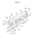
- the cap assembly 30 includes a short-circuit member 56 which short-circuits (e.g., electrically couples) the positive electrode 11 and the negative electrode 12, the short-circuit member 56 is coupled to (e.g., electrically connected to) the cap plate 31 and is deformed (e.g., inverted) to contact (e.g., to be connected to) the second terminal 22 when internal pressure of the rechargeable battery 101 is increased (e.g., when internal pressure of the rechargeable battery 101 is increased above a predetermined level).
- a short-circuit member 56 which short-circuits (e.g., electrically couples) the positive electrode 11 and the negative electrode 12
- the short-circuit member 56 is coupled to (e.g., electrically connected to) the cap plate 31 and is deformed (e.g., inverted) to contact (e.g., to be connected to) the second terminal 22 when internal pressure of the rechargeable battery 101 is increased (e.g., when internal pressure of the rechargeable battery 101 is increased above a predetermined level
- the short-circuit opening 37 is formed in the cap plate 31, and the short-circuit member 56 is disposed between the upper insulating member 54 and the cap plate 31 at the short-circuit opening 37.
- the short-circuit member 56 includes a curved portion 56a which is convexly curved downwards in an arc shape and an edge portion 56b which is formed outside of (e.g., around) the curved portion 56a and fixed to the cap plate 31.
- the short-circuit member 56 convexly curved downwards, may be deformed to be convexly curved upwards such that the short-circuit protrusion 22c contacts the short-circuit member 56 when internal pressure of the rechargeable battery 101 is increased.
- the upper insulating member 54 includes supporting protrusions 543 and 545 which are formed to protrude from respective lateral ends of the upper insulating member 54 along a length direction thereof.
- the upper insulating member 54 includes a lower plate formed in a rectangular plate shape and a side wall protruding from lateral ends of the lower plate.
- the supporting protrusions 543 and 545 may contact supporting steps 22a and 22b which are formed in the second terminal 22 and support the second terminal 22.
- the supporting steps 22a and 22b are formed to be stepped from respective lateral ends of the second terminal 22 along a length direction thereof and are respectively coupled to (e.g., combined to) the supporting protrusions 543 and 545.
- the supporting protrusions 543 and 545 are formed with a catching portion protruding towards the inside of the lower plate, the catching portion contacts top surfaces of the supporting steps 22a and 22b and supports the second terminal 22.
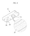
- the second terminal 22 is formed in a rectangular plate shape, and the short-circuit protrusion 22c protruding towards the short-circuit member 56 may be integrally formed with the second terminal 22 at a bottom side thereof.
- the present invention is no limited thereto, and the short-circuit protrusion 22c may be attached to the second terminal 22 by, for example, welding and the like.
- the second terminal 22 is formed with a terminal opening 22d (e.g., a terminal hole) and a supporting groove 22e into which a supporting protrusion formed in the cap plate is inserted.
- a terminal opening 22d e.g., a terminal hole
- a supporting groove 22e into which a supporting protrusion formed in the cap plate is inserted.
- the short-circuit protrusion 22c is formed to protrude downwards from a bottom side of the second terminal 22 and is formed to be elongated in (e.g., protrude in) a circular ring shape.
- the present invention is no limited thereto, and the short-circuit protrusion 22c may be formed to protrude in various shapes.
- the surface roughness (R a ) of the short-circuit protrusion 22c is greater than that of the cap plate 31.
- the surface of the second terminal 22 may be processed by various methods, for example, a sandblasting process, acid or base etching, stamping using a stamp with micro-sized protrusions, and the like.
- the short-circuit protrusion 22c is formed with micro-sized protrusions 22f, and these micro-sized protrusions 22f may be formed over substantially the entire surface area of the second terminal 22 as all of the surface area is processed.
- the surface roughness (R a ) of the short-circuit protrusion 22c may be about 1.3 to about 10 times greater than that of the cap plate 31.
- the average length of the micro-sized protrusions 22f producing the surface roughness (R a ) of the short-circuit protrusion 22c may be about 0.5 ⁇ m to about 100 ⁇ m.
- the deformed short-circuit member 56 has a larger contact area when contacting the short-circuit protrusion 22c.
- the short-circuit member 56 may be more easily melted due to the contact resistance between the short-circuit protrusion 22c and the short-circuit member 56, thereby stopping the short-circuit.
- FIG. 5A is a photograph showing a part of the second terminal before the surface processing
- FIG. 5B is a photograph showing the part of the second terminal after the surface processing.
- the second terminal 22 has a smooth surface before the surface processing, but the surface roughness is increased, as shown in FIG. 5B , after surface processing by acid etching.
- impurities on the surface of the second terminal 22 may be removed if the surface is processed by acid etching and organic materials such as oil, carbon, and the like may also be removed (e.g., completely removed).
- a sandblasting process is a process in which the surface of the second terminal 22 is processed by being sprayed with tiny materials such as sand and the like, which increases the surface roughness of the second terminal 22.
- a stamping process is a process in which the short-circuit protrusion and the second terminal 22 are stamped with a stamp having micro-sized protrusions, which increases the surface roughness of the short-circuit protrusion 22c.
- the above processes may be used individually or in combination with each other or with other processes in order to achieve the desired level of surface roughness.
- FIG. 6 is a perspective view of a second terminal according to a second example embodiment.
- a rechargeable battery according to the present example embodiment has substantially the same structure as the first example embodiment described above, except for a second terminal, a repeated description of the same structure will be omitted.
- the second terminal 70 is formed in a rectangular plate shape, and a short-circuit protrusion 71 is formed to protrude towards the short-circuit member 56 from a bottom side of the second terminal 70.
- the second terminal 70 is formed with a terminal opening 72 (e.g., a terminal hole) into which the connecting terminal is inserted, and a supporting groove 73 into which the supporting protrusion formed in the cap plate 31 is inserted.
- a terminal opening 72 e.g., a terminal hole
- a supporting groove 73 into which the supporting protrusion formed in the cap plate 31 is inserted.
- the short-circuit protrusion 71 protrudes downwards from a bottom side of the second terminal 70 and is elongated in (e.g., protrude in) a circular ring shape.
- the present invention is not limited thereto, and the short-circuit protrusion 71 may be formed in various suitable shapes.
- the surface roughness (R a ) of the short-circuit protrusion 71 may be greater than that of the cap plate 31.
- the surface roughness (R a ) of the short-circuit protrusion 71 may be greater than that of the parts of the second terminal 70 other than the short-circuit protrusion 71.
- the surface of the short-circuit protrusion 71 may be processed, and the surface of the second terminal 70 other than the short-circuit protrusion 71 need not be processed.
- the surface of the short-circuit protrusion 71 may be processed by various suitable methods, for example, a sandblasting process, acid or base etching, and stamping using a stamp with micro-sized protrusions, and/or the like.
- the short-circuit protrusion 71 may be etched by an acid or base, and the short-circuit protrusion 71, with its surface processed, may be coupled to (e.g., fixed to) the second terminal by, for example, welding.
- the short-circuit protrusion 71 may be formed with micro-sized protrusions 75, and these micro-sized protrusions 75 may be formed only in the short-circuit protrusion 71 of the second terminal 70.
- the surface roughness (R a ) of the short-circuit protrusion 71 may be about 1.3 to about 10 times greater than that of the other remaining parts of the second terminal 70 other than the short-circuit protrusion 71.
- the average length of the micro-sized protrusions 75 producing the surface roughness (R a ) of the short-circuit protrusion 71 may be about 0.5 ⁇ m to about 100 ⁇ m.
- the deformed short-circuit member 56 has a larger contact area when contacting the short-circuit protrusion 71.
- contact resistance between the short-circuit member 56 and the short-circuit protrusion 71 may be reduced.
Landscapes
- Chemical & Material Sciences (AREA)
- Chemical Kinetics & Catalysis (AREA)
- Electrochemistry (AREA)
- General Chemical & Material Sciences (AREA)
- Engineering & Computer Science (AREA)
- Manufacturing & Machinery (AREA)
- Connection Of Batteries Or Terminals (AREA)
Applications Claiming Priority (1)
| Application Number | Priority Date | Filing Date | Title |
|---|---|---|---|
| KR1020130119955A KR101775545B1 (ko) | 2013-10-08 | 2013-10-08 | 단락 돌기를 갖는 이차 전지 |
Publications (3)
| Publication Number | Publication Date |
|---|---|
| EP2860796A2 true EP2860796A2 (fr) | 2015-04-15 |
| EP2860796A3 EP2860796A3 (fr) | 2015-04-22 |
| EP2860796B1 EP2860796B1 (fr) | 2018-04-18 |
Family
ID=51660379
Family Applications (1)
| Application Number | Title | Priority Date | Filing Date |
|---|---|---|---|
| EP14187992.4A Active EP2860796B1 (fr) | 2013-10-08 | 2014-10-07 | Batterie rechargeable présentant une protrusion de court-circuit |
Country Status (3)
| Country | Link |
|---|---|
| US (1) | US9819003B2 (fr) |
| EP (1) | EP2860796B1 (fr) |
| KR (1) | KR101775545B1 (fr) |
Cited By (2)
| Publication number | Priority date | Publication date | Assignee | Title |
|---|---|---|---|---|
| EP2927987A1 (fr) * | 2014-03-31 | 2015-10-07 | Samsung SDI Co., Ltd. | Batterie rechargeable présentant un élément d'isolation supérieur |
| EP3664179A1 (fr) * | 2018-12-05 | 2020-06-10 | Hilti Aktiengesellschaft | Dispositif formant bloc d'accumulateur et procédé de fonctionnement du dispositif formant bloc d'accumulateur |
Families Citing this family (5)
| Publication number | Priority date | Publication date | Assignee | Title |
|---|---|---|---|---|
| KR102207903B1 (ko) * | 2016-07-12 | 2021-01-25 | 삼성에스디아이 주식회사 | 이차 전지 |
| ES2843498T3 (es) * | 2016-12-02 | 2021-07-19 | Contemporary Amperex Technology Co Ltd | Conjunto de cubierta superior para la batería de alimentación y la batería de potencia que tiene la misma |
| KR102799929B1 (ko) * | 2019-07-02 | 2025-04-28 | 삼성에스디아이 주식회사 | 이차전지 |
| JP7673720B2 (ja) * | 2022-11-04 | 2025-05-09 | トヨタ自動車株式会社 | 蓄電セル |
| KR20250090253A (ko) | 2025-06-02 | 2025-06-19 | 윤종석 | 조건 기반 위장형 이미지 암호화 메시지 시스템 및 방법 |
Family Cites Families (10)
| Publication number | Priority date | Publication date | Assignee | Title |
|---|---|---|---|---|
| JP3454594B2 (ja) | 1994-12-07 | 2003-10-06 | 日新製鋼株式会社 | 安全弁用オーステナイト系ステンレス鋼板およびこれを用いた密閉型電池の安全弁 |
| TW457305B (en) | 1996-05-23 | 2001-10-01 | Toyo Kohan Co Ltd | Plated steel sheet for battery container, manufacturing method therefor, and battery container and battery using the same |
| JP2005093239A (ja) | 2003-09-17 | 2005-04-07 | Sony Corp | 電池 |
| KR100658686B1 (ko) * | 2005-10-31 | 2006-12-15 | 삼성에스디아이 주식회사 | 이차 전지 모듈 |
| US9246140B2 (en) * | 2009-07-09 | 2016-01-26 | Samsung Sdi Co., Ltd. | Rechargeable battery with a cap assembly having a first tab located outside of the case |
| US8440336B2 (en) | 2009-12-08 | 2013-05-14 | Samsung Sdi Co., Ltd. | Rechargeable battery with short circuit member |
| US8642196B2 (en) | 2011-06-08 | 2014-02-04 | Samsung Sdi Co., Ltd. | Rechargeable battery |
| KR101265202B1 (ko) | 2011-06-08 | 2013-05-27 | 로베르트 보쉬 게엠베하 | 이차 전지 |
| KR101724010B1 (ko) | 2011-10-19 | 2017-04-07 | 삼성에스디아이 주식회사 | 이차 전지 |
| DE102012200868A1 (de) | 2012-01-23 | 2013-07-25 | Robert Bosch Gmbh | Batteriezelle mit einer Überspannungsschutzvorrichtung |
-
2013
- 2013-10-08 KR KR1020130119955A patent/KR101775545B1/ko active Active
-
2014
- 2014-07-29 US US14/445,698 patent/US9819003B2/en active Active
- 2014-10-07 EP EP14187992.4A patent/EP2860796B1/fr active Active
Non-Patent Citations (1)
| Title |
|---|
| None |
Cited By (5)
| Publication number | Priority date | Publication date | Assignee | Title |
|---|---|---|---|---|
| EP2927987A1 (fr) * | 2014-03-31 | 2015-10-07 | Samsung SDI Co., Ltd. | Batterie rechargeable présentant un élément d'isolation supérieur |
| US9768436B2 (en) | 2014-03-31 | 2017-09-19 | Samsung Sdi Co., Ltd. | Rechargeable battery having top insulating member |
| EP3664179A1 (fr) * | 2018-12-05 | 2020-06-10 | Hilti Aktiengesellschaft | Dispositif formant bloc d'accumulateur et procédé de fonctionnement du dispositif formant bloc d'accumulateur |
| WO2020114800A1 (fr) * | 2018-12-05 | 2020-06-11 | Hilti Aktiengesellschaft | Arrangement bloc de batterie et procédé de fonctionnement de l'arrangement bloc de batterie |
| US11799123B2 (en) | 2018-12-05 | 2023-10-24 | Hilti Aktiengesellschaft | Rechargeable battery pack apparatus and method for operating the rechargeable battery pack apparatus |
Also Published As
| Publication number | Publication date |
|---|---|
| KR20150041429A (ko) | 2015-04-16 |
| US9819003B2 (en) | 2017-11-14 |
| US20150099145A1 (en) | 2015-04-09 |
| KR101775545B1 (ko) | 2017-09-06 |
| EP2860796A3 (fr) | 2015-04-22 |
| EP2860796B1 (fr) | 2018-04-18 |
Similar Documents
| Publication | Publication Date | Title |
|---|---|---|
| EP2273587B1 (fr) | Batterie rechargeable | |
| CN105280874B (zh) | 二次电池 | |
| EP2860796B1 (fr) | Batterie rechargeable présentant une protrusion de court-circuit | |
| US9118071B2 (en) | Rechargeable battery | |
| EP2913868B1 (fr) | Batterie secondaire et son procédé de fabrication | |
| US10084164B2 (en) | Secondary battery | |
| EP3065193B1 (fr) | Batterie rechargeable ayant un couvercle | |
| EP4340117A1 (fr) | Batterie secondaire | |
| KR102340111B1 (ko) | 상부 절연부재를 갖는 이차 전지 | |
| US7919206B2 (en) | Electrode assembly and secondary battery using the same | |
| KR20210021842A (ko) | 이차전지 | |
| CN111971840A (zh) | 电极组件和包括该电极组件的二次电池 | |
| KR20180027266A (ko) | 이차전지 | |
| KR20130054845A (ko) | 이차 전지 | |
| EP2846380A1 (fr) | Batterie rechargeable présentant un élément de court-circuit | |
| US20140308575A1 (en) | Rechargeable battery | |
| US20130196219A1 (en) | Rechargeable battery | |
| US20160197379A1 (en) | Secondary battery | |
| EP3509127B1 (fr) | Batterie secondaire | |
| US11664523B2 (en) | Secondary battery | |
| US20100310925A1 (en) | Cylindrical lithium ion secondary battery | |
| KR100778980B1 (ko) | 리튬 이차전지 | |
| US10205154B2 (en) | Rechargeable battery having short-circuit protrusion | |
| KR20160015778A (ko) | 내진동 특성이 향상된 원통형 전지 | |
| US9893346B2 (en) | Rechargeable battery having short-circuit member |
Legal Events
| Date | Code | Title | Description |
|---|---|---|---|
| PUAL | Search report despatched |
Free format text: ORIGINAL CODE: 0009013 |
|
| PUAI | Public reference made under article 153(3) epc to a published international application that has entered the european phase |
Free format text: ORIGINAL CODE: 0009012 |
|
| 17P | Request for examination filed |
Effective date: 20141007 |
|
| AK | Designated contracting states |
Kind code of ref document: A2 Designated state(s): AL AT BE BG CH CY CZ DE DK EE ES FI FR GB GR HR HU IE IS IT LI LT LU LV MC MK MT NL NO PL PT RO RS SE SI SK SM TR |
|
| AX | Request for extension of the european patent |
Extension state: BA ME |
|
| AK | Designated contracting states |
Kind code of ref document: A3 Designated state(s): AL AT BE BG CH CY CZ DE DK EE ES FI FR GB GR HR HU IE IS IT LI LT LU LV MC MK MT NL NO PL PT RO RS SE SI SK SM TR |
|
| AX | Request for extension of the european patent |
Extension state: BA ME |
|
| RIC1 | Information provided on ipc code assigned before grant |
Ipc: H01M 2/34 20060101AFI20150318BHEP Ipc: H01M 2/30 20060101ALI20150318BHEP Ipc: H01M 2/04 20060101ALN20150318BHEP |
|
| R17P | Request for examination filed (corrected) |
Effective date: 20151022 |
|
| RBV | Designated contracting states (corrected) |
Designated state(s): AL AT BE BG CH CY CZ DE DK EE ES FI FR GB GR HR HU IE IS IT LI LT LU LV MC MK MT NL NO PL PT RO RS SE SI SK SM TR |
|
| 17Q | First examination report despatched |
Effective date: 20170317 |
|
| GRAP | Despatch of communication of intention to grant a patent |
Free format text: ORIGINAL CODE: EPIDOSNIGR1 |
|
| INTG | Intention to grant announced |
Effective date: 20171108 |
|
| GRAS | Grant fee paid |
Free format text: ORIGINAL CODE: EPIDOSNIGR3 |
|
| GRAA | (expected) grant |
Free format text: ORIGINAL CODE: 0009210 |
|
| AK | Designated contracting states |
Kind code of ref document: B1 Designated state(s): AL AT BE BG CH CY CZ DE DK EE ES FI FR GB GR HR HU IE IS IT LI LT LU LV MC MK MT NL NO PL PT RO RS SE SI SK SM TR |
|
| REG | Reference to a national code |
Ref country code: GB Ref legal event code: FG4D |
|
| REG | Reference to a national code |
Ref country code: CH Ref legal event code: EP |
|
| REG | Reference to a national code |
Ref country code: AT Ref legal event code: REF Ref document number: 991367 Country of ref document: AT Kind code of ref document: T Effective date: 20180515 |
|
| REG | Reference to a national code |
Ref country code: IE Ref legal event code: FG4D |
|
| REG | Reference to a national code |
Ref country code: DE Ref legal event code: R096 Ref document number: 602014024021 Country of ref document: DE |
|
| REG | Reference to a national code |
Ref country code: NL Ref legal event code: MP Effective date: 20180418 |
|
| REG | Reference to a national code |
Ref country code: LT Ref legal event code: MG4D |
|
| PG25 | Lapsed in a contracting state [announced via postgrant information from national office to epo] |
Ref country code: NL Free format text: LAPSE BECAUSE OF FAILURE TO SUBMIT A TRANSLATION OF THE DESCRIPTION OR TO PAY THE FEE WITHIN THE PRESCRIBED TIME-LIMIT Effective date: 20180418 |
|
| REG | Reference to a national code |
Ref country code: FR Ref legal event code: PLFP Year of fee payment: 5 |
|
| PG25 | Lapsed in a contracting state [announced via postgrant information from national office to epo] |
Ref country code: LT Free format text: LAPSE BECAUSE OF FAILURE TO SUBMIT A TRANSLATION OF THE DESCRIPTION OR TO PAY THE FEE WITHIN THE PRESCRIBED TIME-LIMIT Effective date: 20180418 Ref country code: SE Free format text: LAPSE BECAUSE OF FAILURE TO SUBMIT A TRANSLATION OF THE DESCRIPTION OR TO PAY THE FEE WITHIN THE PRESCRIBED TIME-LIMIT Effective date: 20180418 Ref country code: FI Free format text: LAPSE BECAUSE OF FAILURE TO SUBMIT A TRANSLATION OF THE DESCRIPTION OR TO PAY THE FEE WITHIN THE PRESCRIBED TIME-LIMIT Effective date: 20180418 Ref country code: BG Free format text: LAPSE BECAUSE OF FAILURE TO SUBMIT A TRANSLATION OF THE DESCRIPTION OR TO PAY THE FEE WITHIN THE PRESCRIBED TIME-LIMIT Effective date: 20180718 Ref country code: AL Free format text: LAPSE BECAUSE OF FAILURE TO SUBMIT A TRANSLATION OF THE DESCRIPTION OR TO PAY THE FEE WITHIN THE PRESCRIBED TIME-LIMIT Effective date: 20180418 Ref country code: ES Free format text: LAPSE BECAUSE OF FAILURE TO SUBMIT A TRANSLATION OF THE DESCRIPTION OR TO PAY THE FEE WITHIN THE PRESCRIBED TIME-LIMIT Effective date: 20180418 Ref country code: NO Free format text: LAPSE BECAUSE OF FAILURE TO SUBMIT A TRANSLATION OF THE DESCRIPTION OR TO PAY THE FEE WITHIN THE PRESCRIBED TIME-LIMIT Effective date: 20180718 Ref country code: PL Free format text: LAPSE BECAUSE OF FAILURE TO SUBMIT A TRANSLATION OF THE DESCRIPTION OR TO PAY THE FEE WITHIN THE PRESCRIBED TIME-LIMIT Effective date: 20180418 |
|
| PG25 | Lapsed in a contracting state [announced via postgrant information from national office to epo] |
Ref country code: LV Free format text: LAPSE BECAUSE OF FAILURE TO SUBMIT A TRANSLATION OF THE DESCRIPTION OR TO PAY THE FEE WITHIN THE PRESCRIBED TIME-LIMIT Effective date: 20180418 Ref country code: HR Free format text: LAPSE BECAUSE OF FAILURE TO SUBMIT A TRANSLATION OF THE DESCRIPTION OR TO PAY THE FEE WITHIN THE PRESCRIBED TIME-LIMIT Effective date: 20180418 Ref country code: GR Free format text: LAPSE BECAUSE OF FAILURE TO SUBMIT A TRANSLATION OF THE DESCRIPTION OR TO PAY THE FEE WITHIN THE PRESCRIBED TIME-LIMIT Effective date: 20180719 Ref country code: RS Free format text: LAPSE BECAUSE OF FAILURE TO SUBMIT A TRANSLATION OF THE DESCRIPTION OR TO PAY THE FEE WITHIN THE PRESCRIBED TIME-LIMIT Effective date: 20180418 |
|
| REG | Reference to a national code |
Ref country code: AT Ref legal event code: MK05 Ref document number: 991367 Country of ref document: AT Kind code of ref document: T Effective date: 20180418 |
|
| PG25 | Lapsed in a contracting state [announced via postgrant information from national office to epo] |
Ref country code: PT Free format text: LAPSE BECAUSE OF FAILURE TO SUBMIT A TRANSLATION OF THE DESCRIPTION OR TO PAY THE FEE WITHIN THE PRESCRIBED TIME-LIMIT Effective date: 20180820 |
|
| REG | Reference to a national code |
Ref country code: DE Ref legal event code: R097 Ref document number: 602014024021 Country of ref document: DE |
|
| PG25 | Lapsed in a contracting state [announced via postgrant information from national office to epo] |
Ref country code: AT Free format text: LAPSE BECAUSE OF FAILURE TO SUBMIT A TRANSLATION OF THE DESCRIPTION OR TO PAY THE FEE WITHIN THE PRESCRIBED TIME-LIMIT Effective date: 20180418 Ref country code: CZ Free format text: LAPSE BECAUSE OF FAILURE TO SUBMIT A TRANSLATION OF THE DESCRIPTION OR TO PAY THE FEE WITHIN THE PRESCRIBED TIME-LIMIT Effective date: 20180418 Ref country code: SK Free format text: LAPSE BECAUSE OF FAILURE TO SUBMIT A TRANSLATION OF THE DESCRIPTION OR TO PAY THE FEE WITHIN THE PRESCRIBED TIME-LIMIT Effective date: 20180418 Ref country code: RO Free format text: LAPSE BECAUSE OF FAILURE TO SUBMIT A TRANSLATION OF THE DESCRIPTION OR TO PAY THE FEE WITHIN THE PRESCRIBED TIME-LIMIT Effective date: 20180418 Ref country code: EE Free format text: LAPSE BECAUSE OF FAILURE TO SUBMIT A TRANSLATION OF THE DESCRIPTION OR TO PAY THE FEE WITHIN THE PRESCRIBED TIME-LIMIT Effective date: 20180418 Ref country code: DK Free format text: LAPSE BECAUSE OF FAILURE TO SUBMIT A TRANSLATION OF THE DESCRIPTION OR TO PAY THE FEE WITHIN THE PRESCRIBED TIME-LIMIT Effective date: 20180418 |
|
| PLBE | No opposition filed within time limit |
Free format text: ORIGINAL CODE: 0009261 |
|
| STAA | Information on the status of an ep patent application or granted ep patent |
Free format text: STATUS: NO OPPOSITION FILED WITHIN TIME LIMIT |
|
| PG25 | Lapsed in a contracting state [announced via postgrant information from national office to epo] |
Ref country code: SM Free format text: LAPSE BECAUSE OF FAILURE TO SUBMIT A TRANSLATION OF THE DESCRIPTION OR TO PAY THE FEE WITHIN THE PRESCRIBED TIME-LIMIT Effective date: 20180418 Ref country code: IT Free format text: LAPSE BECAUSE OF FAILURE TO SUBMIT A TRANSLATION OF THE DESCRIPTION OR TO PAY THE FEE WITHIN THE PRESCRIBED TIME-LIMIT Effective date: 20180418 |
|
| 26N | No opposition filed |
Effective date: 20190121 |
|
| PG25 | Lapsed in a contracting state [announced via postgrant information from national office to epo] |
Ref country code: SI Free format text: LAPSE BECAUSE OF FAILURE TO SUBMIT A TRANSLATION OF THE DESCRIPTION OR TO PAY THE FEE WITHIN THE PRESCRIBED TIME-LIMIT Effective date: 20180418 |
|
| REG | Reference to a national code |
Ref country code: CH Ref legal event code: PL |
|
| REG | Reference to a national code |
Ref country code: BE Ref legal event code: MM Effective date: 20181031 |
|
| PG25 | Lapsed in a contracting state [announced via postgrant information from national office to epo] |
Ref country code: MC Free format text: LAPSE BECAUSE OF FAILURE TO SUBMIT A TRANSLATION OF THE DESCRIPTION OR TO PAY THE FEE WITHIN THE PRESCRIBED TIME-LIMIT Effective date: 20180418 Ref country code: LU Free format text: LAPSE BECAUSE OF NON-PAYMENT OF DUE FEES Effective date: 20181007 |
|
| REG | Reference to a national code |
Ref country code: IE Ref legal event code: MM4A |
|
| PG25 | Lapsed in a contracting state [announced via postgrant information from national office to epo] |
Ref country code: BE Free format text: LAPSE BECAUSE OF NON-PAYMENT OF DUE FEES Effective date: 20181031 Ref country code: LI Free format text: LAPSE BECAUSE OF NON-PAYMENT OF DUE FEES Effective date: 20181031 Ref country code: CH Free format text: LAPSE BECAUSE OF NON-PAYMENT OF DUE FEES Effective date: 20181031 |
|
| PG25 | Lapsed in a contracting state [announced via postgrant information from national office to epo] |
Ref country code: IE Free format text: LAPSE BECAUSE OF NON-PAYMENT OF DUE FEES Effective date: 20181007 |
|
| PG25 | Lapsed in a contracting state [announced via postgrant information from national office to epo] |
Ref country code: MT Free format text: LAPSE BECAUSE OF NON-PAYMENT OF DUE FEES Effective date: 20181007 |
|
| PG25 | Lapsed in a contracting state [announced via postgrant information from national office to epo] |
Ref country code: TR Free format text: LAPSE BECAUSE OF FAILURE TO SUBMIT A TRANSLATION OF THE DESCRIPTION OR TO PAY THE FEE WITHIN THE PRESCRIBED TIME-LIMIT Effective date: 20180418 |
|
| PG25 | Lapsed in a contracting state [announced via postgrant information from national office to epo] |
Ref country code: MK Free format text: LAPSE BECAUSE OF NON-PAYMENT OF DUE FEES Effective date: 20180418 Ref country code: CY Free format text: LAPSE BECAUSE OF FAILURE TO SUBMIT A TRANSLATION OF THE DESCRIPTION OR TO PAY THE FEE WITHIN THE PRESCRIBED TIME-LIMIT Effective date: 20180418 Ref country code: HU Free format text: LAPSE BECAUSE OF FAILURE TO SUBMIT A TRANSLATION OF THE DESCRIPTION OR TO PAY THE FEE WITHIN THE PRESCRIBED TIME-LIMIT; INVALID AB INITIO Effective date: 20141007 |
|
| PG25 | Lapsed in a contracting state [announced via postgrant information from national office to epo] |
Ref country code: IS Free format text: LAPSE BECAUSE OF FAILURE TO SUBMIT A TRANSLATION OF THE DESCRIPTION OR TO PAY THE FEE WITHIN THE PRESCRIBED TIME-LIMIT Effective date: 20180818 |
|
| REG | Reference to a national code |
Ref country code: DE Ref legal event code: R079 Ref document number: 602014024021 Country of ref document: DE Free format text: PREVIOUS MAIN CLASS: H01M0002340000 Ipc: H01M0050572000 |
|
| P01 | Opt-out of the competence of the unified patent court (upc) registered |
Effective date: 20230528 |
|
| PGFP | Annual fee paid to national office [announced via postgrant information from national office to epo] |
Ref country code: FR Payment date: 20250930 Year of fee payment: 12 |
|
| PGFP | Annual fee paid to national office [announced via postgrant information from national office to epo] |
Ref country code: DE Payment date: 20250930 Year of fee payment: 12 |
|
| PGFP | Annual fee paid to national office [announced via postgrant information from national office to epo] |
Ref country code: GB Payment date: 20251001 Year of fee payment: 12 |