EP2860847A1 - Bewickelter Stator mit optimierter Nutenfüllung, und entsprechende elektrische Maschine - Google Patents
Bewickelter Stator mit optimierter Nutenfüllung, und entsprechende elektrische Maschine Download PDFInfo
- Publication number
- EP2860847A1 EP2860847A1 EP20140177886 EP14177886A EP2860847A1 EP 2860847 A1 EP2860847 A1 EP 2860847A1 EP 20140177886 EP20140177886 EP 20140177886 EP 14177886 A EP14177886 A EP 14177886A EP 2860847 A1 EP2860847 A1 EP 2860847A1
- Authority
- EP
- European Patent Office
- Prior art keywords
- stator
- tooth
- teeth
- stator according
- coil
- Prior art date
- Legal status (The legal status is an assumption and is not a legal conclusion. Google has not performed a legal analysis and makes no representation as to the accuracy of the status listed.)
- Granted
Links
Images


Classifications
-
- H—ELECTRICITY
- H02—GENERATION; CONVERSION OR DISTRIBUTION OF ELECTRIC POWER
- H02K—DYNAMO-ELECTRIC MACHINES
- H02K1/00—Details of the magnetic circuit
- H02K1/06—Details of the magnetic circuit characterised by the shape, form or construction
- H02K1/12—Stationary parts of the magnetic circuit
- H02K1/14—Stator cores with salient poles
- H02K1/146—Stator cores with salient poles consisting of a generally annular yoke with salient poles
- H02K1/148—Sectional cores
-
- H—ELECTRICITY
- H02—GENERATION; CONVERSION OR DISTRIBUTION OF ELECTRIC POWER
- H02K—DYNAMO-ELECTRIC MACHINES
- H02K3/00—Details of windings
- H02K3/32—Windings characterised by the shape, form or construction of the insulation
- H02K3/34—Windings characterised by the shape, form or construction of the insulation between conductors or between conductor and core, e.g. slot insulation
- H02K3/345—Windings characterised by the shape, form or construction of the insulation between conductors or between conductor and core, e.g. slot insulation between conductor and core, e.g. slot insulation
-
- H—ELECTRICITY
- H02—GENERATION; CONVERSION OR DISTRIBUTION OF ELECTRIC POWER
- H02K—DYNAMO-ELECTRIC MACHINES
- H02K1/00—Details of the magnetic circuit
- H02K1/06—Details of the magnetic circuit characterised by the shape, form or construction
- H02K1/12—Stationary parts of the magnetic circuit
- H02K1/18—Means for mounting or fastening magnetic stationary parts on to, or to, the stator structures
- H02K1/185—Means for mounting or fastening magnetic stationary parts on to, or to, the stator structures to outer stators
Definitions
- the invention relates to a wound stator for a rotating electrical machine and to the corresponding rotating electrical machine.
- the invention relates to the field of rotating electrical machines such as motors, alternators, or alternator-starters.
- Electrical machines comprising a stator and a rotor integral with a shaft.
- the rotor may be integral with a driving shaft and / or driven and may belong to a rotating electrical machine in the form of an alternator as described in document EP0803962 or an electric motor as described in the document EP0831580 .
- the electric machine has a housing carrying the stator.
- This housing is configured to rotate the shaft for example by means of bearings, such as ball bearings and / or needle.
- the rotor may comprise a body made of laminated sheet metal, which comprises housing. Permanent magnets are positioned inside at least some of these dwellings as visible for example in the Figures 1 and 2 of the document EP0803962 .
- the machine comprises a claw rotor and a stator body in the form of a package of sheets with teeth for mounting coils belonging to the stator winding.
- the body of the stator has notches open towards the inside delimited each by two consecutive teeth. These teeth have parallel edges, a strip of material, called breech existing between the bottom of the notches and the outer periphery of the body.
- the stator teeth of the coils made from a wire wound on several turns.
- the son consist for example of a copper wire coated with enamel.
- Two coils are implanted in the same notch, each coil being wound around one of the teeth delimiting the notch via a coil insulator.
- the coils are interconnected together, for example by welding or using a connector to form a phase of the machine which may be of the polyphase type.
- the Japanese document JP2004350450 teaches the use of a wire-shaped flat, that is to say, rectangular section, to make each coil.
- a wire-shaped flat that is to say, rectangular section
- the use of parallel-flanked teeth combined with that of a stair-shaped insulator which makes it necessary to produce a flat surface of a fixed size does not make it possible to obtain a notch filling rate exceeding 50%.
- the notch filling rate corresponds to the ratio between the section of bare conductive wire and the complete section of the notch.
- the invention aims to maximize the filling rate of the notches of the stator to improve the performance of the machine.
- the subject of the invention is a wound stator of a rotating electrical machine comprising a yoke, teeth distributed on an internal periphery of said yoke extending inwardly of said stator and delimiting two-by-two notches, as well as bobbins formed around each tooth from a yarn having a substantially rectangular section, characterized in that the lateral flanks of the same tooth are inclined with respect to each other, so that two flanks side of two adjacent teeth facing each other corresponding to the edges delimiting a notch are parallel to each other.
- the use in combination of notches with parallel edges and a wire of rectangular section makes it possible to maximize the filling rate of the notch by making it possible in particular to fill in an easy manner the spaces at the angles of the notch . Thanks to the invention, it will be It is possible to obtain fill rates higher than 50% up to 60% in some applications.
- the stator further includes a coil insulator mounted around each tooth.
- the rectangular-shaped coil wire has its largest side oriented parallel to the lateral flanks of the teeth delimiting the notch in which said coil wire is positioned.
- the rectangular-shaped coil wire has its largest side oriented perpendicularly to the lateral flanks of the teeth delimiting the notch in which said coil wire is positioned.
- the coil wire has a square section.
- the stator has reported teeth.
- the winding of the coil wire around an added tooth is performed before assembling the reported teeth to form the stator.
- each reported tooth has two branches corresponding to a portion of the yoke, said branches of two adjacent teeth being able to cooperate with each other to form said stator.
- the reported teeth comprise fixing means on an annular wall forming said stator yoke.
- each tooth has a tooth root.
- each tooth root extends parallel to the bottom of the corresponding notch.
- the coil insulation is made in two parts.
- the two parts of the coil insulator are cut in a horizontal plane perpendicular to an axis of said stator.
- the stator has slots located on either side of each tooth adapted to receive projections of said coil insulator.
- the stator further comprises assembly means for fixing with a rotating electrical machine housing.
- the invention also relates to a rotating electrical machine provided with a wound stator according to the invention.
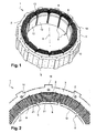
- the Figures 1, 2 , 3a and 3b show an X-axis stator 1 for a rotating electrical machine, such as an alternator, a motor or an alternator.
- This stator 1 comprises teeth 2 regularly distributed on the inner periphery of a yoke 3 and extending towards the inside of the stator 1.
- the stator 1 also comprises notches 5, two consecutive notches 5 being separated by a tooth 2 intended to to receive a coil 8.
- the yoke 3 consists of a strip of material connecting the teeth 2 between them extending between the bottom of the notches 5 and the outer periphery of the stator 1.
- the body of the stator 1 is made in the form of a stack of sheets of ferromagnetic material extending in a radial plane perpendicular to the axis X. In the radial plane, the plates of form The sheets are cut so as to delimit the contour of each tooth 2. The sheets are held by means of rivets 10 passing axially from one side to the stack of sheets for forming a stator 1 manipulated and transportable.
- two coils 8 are implanted in the same notch 5.
- Each coil 8 is wound around one of the teeth 2 delimiting the notch 5 by means of a coil insulator 9 visible on the Figures 3a, 3b and 5 and more specifically described below.
- the coils 8 are interconnected with each other, for example by welding or with the aid of a connector (not shown) to form a phase of the machine which may be of the polyphase type.
- the stator 1 is intended to be installed around a rotor so that the free ends of the teeth 2 delimit, in known manner, an air gap with the outer periphery of the rotor of the rotating electrical machine.
- the rotor may comprise a body made of laminated sheet which has housing. Permanent magnets are positioned inside at least some of these dwellings as visible for example in the Figures 1 and 2 of the document EP0803962 .
- the rotor of the machine may be a claw rotor as in the document FR2890798 , or with salient poles.
- the rotor with claws or salient poles may also include permanent magnets.
- each tooth 2 has lateral flanks 21 parallel to the axis X of the stator 1 which are inclined with respect to each other.
- the inclination of the flanks 21 is such that two sidewalls 21 facing each other corresponding to the edges delimiting a notch 5 are parallel to one another.
- the angle ⁇ between two lateral flanks 21 which intersect along a straight line located towards the inside of the stator 1 (cf. figure 3a ) is for example between 10 and 30 degrees.
- Each tooth 2 also has axial end faces 22 perpendicular to the X axis connected to each other by the lateral flanks 21. These faces 22 thus have a substantially trapezoidal view in plan view, the largest side of which is located on the side of the cylinder head 3.
- Each tooth 2 further comprises a tooth root 12 which extends on either side of the portion of the tooth 2 around which the coil 8 is wound.
- the portions of the tooth roots 12 of two adjacent teeth 2 turned one towards the other extend substantially parallel to the bottom of the corresponding notch 5.
- This notch configuration combined with the use of a wire 13 with a substantially rectangular section (flattened shape) to produce the coils 8 makes it possible to maximize the filling rate of the notches 5 by facilitating in particular the filling of the notches 5 at the level of the angles between the teeth 2 and the cylinder head 3 (cf. Figures 3a and 3b ).
- the wire 13 of rectangular shape has its largest side oriented perpendicularly to the lateral flanks 21 of the teeth 2.
- the wire 13 is wound on several turns around a tooth 2 in a compact manner so that each half-notch is filled by three layers C1, C2, C3 of six turns each or 18 turns per half-notch.
- Each notch 5 is thus filled by 36 turns in total.
- the son 13 consist of an electrically conductive wire, for example a copper wire and / or aluminum, coated with an electrical insulator, such as enamel.
- each notch 5 it will be possible to modify the number of turns contained in each notch 5 by varying the number of layers of turns and / or the number of turns in each layer of turn C1, C2, C3 or in some of them only, and the section of the wire 13. It will also be possible to change the orientation of the wire 13 of rectangular shape. So, in this embodiment of the figure 3b , the wire 13 has its largest side oriented parallel to the lateral flanks 21 of the teeth 2. In the example shown, there are 3 turns per layer C1, C2, C3, or 9 turns per half-notches and therefore 18 turns per notch 5.
- the stator 1 also comprises dovetail-shaped assembly means 16 extending from the outer periphery of the yoke for attachment with a housing (not shown) of the machine provided with bearings for mounting rotating the rotor shaft.
- the stator 1 is preferably with teeth 2 reported.
- Each tooth insert 2 comprises in this case two branches 17 corresponding to a circumferential portion of the yoke 3 which extend on either side of the portion of the tooth 2 carrying the coil 8.
- Complementary connecting means 18 are arranged on the end faces of the branches 17. These means 18 allow to connect the branches 17 of two adjacent teeth 2 in position in which the branches 17 of these two teeth 2 are in the extension of one another. It is thus possible to make the arms 17 work together in an annular manner so as to form a ring of teeth 2.
- each tooth 2 attached is inclined side-to-side with respect to the other, so that when the stator 1 is assembled, two adjacent teeth 2 delimit a notch 5 with parallel edges in pairs.
- the stator 1 thus formed will then be fixed to the housing by means of the assembly means 16 extending from an outer periphery of the branches 17 of each tooth 2.
- stator 1 can be made in one piece.
- the figure 5 shows a coil insulator 9 intended to be positioned around each tooth 2.
- This insulator 9 is an electrical insulator made here of electrically insulating material and moldable for example plastic such as PA 6.6.
- the insulator 9 has a body 91 formed by two parts 92 cut vertically, a single portion being shown in the figure. These parts are intended to be assembled for example by snapping around the tooth 2.
- the body 91 comprises a frame 93 positioned around a tooth 2.
- the body 91 further comprises a front edge 94 and a rear flange 95 defining with the walls of the frame 93 a mounting groove of the coil 8.
- the frame 93 substantially flat face may, however, include indentations at its periphery to facilitate the guiding of the wire 13 during the operation of winding.
- the rear flange 95 is intended to be positioned near the yoke 3 while the front flange 94 is located on the side of the tooth root 12.
- the two parts 92 can be cut vertically relative to each other according to a median plane or not of the insulation 9.
- the insulator 9 takes the form of a thin membrane, made of an electrically insulating material and heat conductor, for example an aramid material of Nomex type (trademark). This thin membrane is folded so that the insulator 9 is pressed against the faces of a notch 5 in order to isolate each coil 8 relative to the corresponding tooth 2.
- the stator 1 is formed by a plurality of teeth 2 reported. On the side of their free end, each tooth 2 comprises a tooth root 12.
- the stator 1 further comprises the support 3 of annular shape of axial orientation also made of laminated sheet corresponding to the yoke 3 of the stator 1.
- Assembly means 30 intervene between the support 3 and the teeth 2. These assembly means 30 are formed by a tenon 31 and a mortise 32 made in the inner wall of the support 3. Alternatively, the mortise 32 is made in the tooth 2, while the pin 31 belongs to the support 3. Alternatively, the assembly between the teeth 2 and the support 3 is made by press fitting, gluing, or welding.
- the number of teeth 2 of the stator 1 equal to 12 for the realization of the figure 1 or at 36 for carrying out the figure 6 and the section of the yoke 3 and teeth 2 may vary depending on the application to adapt the electrical performance of the machine.
- the teeth 2 may not be distributed circumferentially in a regular manner.
- the teeth 2 are devoid of a tooth root.
- the parts 92 are positioned on either side of the tooth 2 and assembled together by snapping.
- the insulator 9 thus formed is retained radially on the tooth by the tooth root 12.
- the wire 13 is wound compactly around the coil insulator 9 and easy and fast since this is performed outside the notches 5 in the case of teeth 2 reported.
- the winding is performed for example on three layers of windings C1, C2, C3 superimposed on each other.
- the preformed assembly comprising a coil insulation 9 and a coil 8 is then threaded around the tooth 2 concerned.
- an impregnation operation is then carried out on the winding of the stator 1 by an impregnating varnish.
- the stator 1 is heated as well as the varnish to be introduced in the liquid state drop by drop in the coils 8.
- the impregnation operation may be carried out by dipping partial and rolling stator assembled in a bath of impregnating varnish. This technique is particularly well suited to the invention in that the yoke 3 is reported relative to the housing.
- the impregnation operation can be carried out under vacuum or by completely simple dipping of the stator 1 in a bath of impregnating varnish.
- the varnish is cooled by polymerizing.
- the varnish is for example based on epoxy resin, unsaturated polyester resin or silicone resin.
- accelerators it is possible to add accelerators to the resins in order to reduce the duration of the impregnation.
- the rotating electrical machine may belong to a motor vehicle and be in the above manner an alternator, an alternator-starter which is a reversible alternator, an electric motor or an electromagnetic retarder.
- the rotor may be a rotor with permanent magnets with several magnets per housing subjected to the action of a spring as described in the application FR12 / 54733 filed on 24/20172012 .
Landscapes
- Engineering & Computer Science (AREA)
- Power Engineering (AREA)
- Insulation, Fastening Of Motor, Generator Windings (AREA)
- Iron Core Of Rotating Electric Machines (AREA)
Applications Claiming Priority (1)
| Application Number | Priority Date | Filing Date | Title |
|---|---|---|---|
| FR1357216A FR3009141B1 (fr) | 2013-07-23 | 2013-07-23 | Stator bobine a remplissage d'encoches optimise et machine electrique correspondante |
Publications (2)
| Publication Number | Publication Date |
|---|---|
| EP2860847A1 true EP2860847A1 (de) | 2015-04-15 |
| EP2860847B1 EP2860847B1 (de) | 2022-06-08 |
Family
ID=49713174
Family Applications (1)
| Application Number | Title | Priority Date | Filing Date |
|---|---|---|---|
| EP14177886.0A Active EP2860847B1 (de) | 2013-07-23 | 2014-07-21 | Bewickelter Stator mit optimierter Nutenfüllung, und entsprechende elektrische Maschine |
Country Status (2)
| Country | Link |
|---|---|
| EP (1) | EP2860847B1 (de) |
| FR (1) | FR3009141B1 (de) |
Cited By (2)
| Publication number | Priority date | Publication date | Assignee | Title |
|---|---|---|---|---|
| EP3748816A1 (de) * | 2019-06-03 | 2020-12-09 | Hamilton Sundstrand Corporation | Elektrische maschinen |
| FR3128330A1 (fr) | 2021-10-20 | 2023-04-21 | Francois Bernot | Armature magnétique à dents amovibles |
Families Citing this family (2)
| Publication number | Priority date | Publication date | Assignee | Title |
|---|---|---|---|---|
| FR3041184A1 (fr) * | 2015-09-11 | 2017-03-17 | Valeo Equip Electr Moteur | Stator de machine electrique tournante muni de toles fixees par rivetage ou bouterollage |
| CN110858732B (zh) * | 2018-08-24 | 2022-04-19 | 广东威灵电机制造有限公司 | 定子和电机 |
Citations (10)
| Publication number | Priority date | Publication date | Assignee | Title |
|---|---|---|---|---|
| FR1254733A (fr) | 1960-04-21 | 1961-02-24 | Williamson Inc T | Indicateur de passage de racles à l'intérieur d'une conduite |
| EP0803962A1 (de) | 1996-04-23 | 1997-10-29 | Bamo Elettroutensili S.r.l. | Blechpaket für Dauermagnetrotoren für Generatoren oder dergleichen |
| EP0831580A2 (de) | 1996-09-21 | 1998-03-25 | AKO-Werke GmbH & Co. KG | Einrichtung zur Antriebsstromsteuerung eines elektrisch kommutierten Permanentmagnet-Motors |
| US20040124733A1 (en) * | 2002-12-25 | 2004-07-01 | Noriaki Yamamoto | Rotating electric machine, motor-driven vehicle and resin insert-molding method |
| JP2004350450A (ja) | 2003-05-23 | 2004-12-09 | Honda Motor Co Ltd | ステータ |
| EP1602554A2 (de) * | 2004-06-03 | 2005-12-07 | Hitachi, Ltd. | Bürstenloser Gleichstrommotor für eine elektrische Servolenkanlage und Verfahren zu dessen Herstellung |
| FR2890798A1 (fr) | 2005-09-13 | 2007-03-16 | Valeo Equip Electr Moteur | Stator de machine electrique tournante polyphasee du type alternateur ou alterno-demarreur |
| EP1806822A1 (de) * | 2004-10-29 | 2007-07-11 | Toyota Jidosha Kabushiki Kaisha | Motorgenerator und diesen tragendes automobil |
| JP2007221913A (ja) * | 2006-02-16 | 2007-08-30 | Sawafuji Electric Co Ltd | 回転電機用電機子 |
| US20090085422A1 (en) * | 2005-11-11 | 2009-04-02 | Sumitomo Electric Industries, Ltd. | Motor Core Component and Motor Component |
Family Cites Families (1)
| Publication number | Priority date | Publication date | Assignee | Title |
|---|---|---|---|---|
| JP4998450B2 (ja) * | 2008-12-09 | 2012-08-15 | トヨタ自動車株式会社 | ステータの製造方法 |
-
2013
- 2013-07-23 FR FR1357216A patent/FR3009141B1/fr active Active
-
2014
- 2014-07-21 EP EP14177886.0A patent/EP2860847B1/de active Active
Patent Citations (10)
| Publication number | Priority date | Publication date | Assignee | Title |
|---|---|---|---|---|
| FR1254733A (fr) | 1960-04-21 | 1961-02-24 | Williamson Inc T | Indicateur de passage de racles à l'intérieur d'une conduite |
| EP0803962A1 (de) | 1996-04-23 | 1997-10-29 | Bamo Elettroutensili S.r.l. | Blechpaket für Dauermagnetrotoren für Generatoren oder dergleichen |
| EP0831580A2 (de) | 1996-09-21 | 1998-03-25 | AKO-Werke GmbH & Co. KG | Einrichtung zur Antriebsstromsteuerung eines elektrisch kommutierten Permanentmagnet-Motors |
| US20040124733A1 (en) * | 2002-12-25 | 2004-07-01 | Noriaki Yamamoto | Rotating electric machine, motor-driven vehicle and resin insert-molding method |
| JP2004350450A (ja) | 2003-05-23 | 2004-12-09 | Honda Motor Co Ltd | ステータ |
| EP1602554A2 (de) * | 2004-06-03 | 2005-12-07 | Hitachi, Ltd. | Bürstenloser Gleichstrommotor für eine elektrische Servolenkanlage und Verfahren zu dessen Herstellung |
| EP1806822A1 (de) * | 2004-10-29 | 2007-07-11 | Toyota Jidosha Kabushiki Kaisha | Motorgenerator und diesen tragendes automobil |
| FR2890798A1 (fr) | 2005-09-13 | 2007-03-16 | Valeo Equip Electr Moteur | Stator de machine electrique tournante polyphasee du type alternateur ou alterno-demarreur |
| US20090085422A1 (en) * | 2005-11-11 | 2009-04-02 | Sumitomo Electric Industries, Ltd. | Motor Core Component and Motor Component |
| JP2007221913A (ja) * | 2006-02-16 | 2007-08-30 | Sawafuji Electric Co Ltd | 回転電機用電機子 |
Cited By (3)
| Publication number | Priority date | Publication date | Assignee | Title |
|---|---|---|---|---|
| EP3748816A1 (de) * | 2019-06-03 | 2020-12-09 | Hamilton Sundstrand Corporation | Elektrische maschinen |
| US11496008B2 (en) | 2019-06-03 | 2022-11-08 | Hamilton Sundstrand Corporation | Electrical machines |
| FR3128330A1 (fr) | 2021-10-20 | 2023-04-21 | Francois Bernot | Armature magnétique à dents amovibles |
Also Published As
| Publication number | Publication date |
|---|---|
| FR3009141B1 (fr) | 2016-10-21 |
| EP2860847B1 (de) | 2022-06-08 |
| FR3009141A1 (fr) | 2015-01-30 |
Similar Documents
| Publication | Publication Date | Title |
|---|---|---|
| EP2677633B1 (de) | Zusammengesetzte Spulenisolierung und entsprechendes elektrisches Maschinenelement | |
| EP2677634B1 (de) | Zwischenverbinder für einen Stator einer elektrischen Maschine und Stator mit einem derartigen Zwischenverbinder | |
| EP3005534B1 (de) | Elektrische maschine mit einem dämpfer für mechanischen widerstand gegen schwingungsbelastung und entsprechender dämpfer | |
| WO2013136021A2 (fr) | Ensemble de flasques de rotor de machine electrique tournante comportant des pales axiales de ventilation favorisant un flux d'air axial a l'interieur du rotor et rotor de machine electrique associe | |
| EP2795765B1 (de) | Schenkelpolläufer mit einer vorrichtung zum isolieren der wicklungen und zugehörige vorrichtung zur isolierung der wicklungen | |
| EP2860847B1 (de) | Bewickelter Stator mit optimierter Nutenfüllung, und entsprechende elektrische Maschine | |
| WO2014041313A1 (fr) | Stator a dents rapportees pour machine electrique tournante et machine electrique tournante correspondante | |
| FR2992493A1 (fr) | Isolant de bobine muni d'une ailette formant un mur electriquement isolant et element de machine electrique associe | |
| WO2014174200A2 (fr) | Élément isolant muni de crochets de maintien de fils de bobinage d'un stator de machine électrique et stator correspondant | |
| EP2896117B1 (de) | Gemischter spulenisolierer aus zwei teilen und entsprechendes bauteil einer elektrischen maschine | |
| EP1251622A1 (de) | Spule für drehende elektrische Maschine | |
| FR2995470A1 (fr) | Isolant de bobine realise en deux parties et element de machine electrique correspondant | |
| EP2846438B1 (de) | Spulenisolierung | |
| FR3023994A1 (fr) | Procede de realisation d'un stator bobine de machine electrique tournante | |
| FR2995472A1 (fr) | Interconnecteur pour stator de machine electrique, cache isolant, et stator de machine electrique correspondants | |
| EP2608363B1 (de) | Flansche für die Unterstützung der Wickelköpfe und Schenkelpol- Rotor mit den Flanschen | |
| WO2018020188A1 (fr) | Machine electrique tournante munie d'un stator avec un bobinage epingle | |
| WO2017093634A1 (fr) | Rotor a griffes de machine electrique tournante a performances magnetiques ameliorees | |
| FR3046707B1 (fr) | Isolant de bobine perfectionne et machine electrique tournante comportant un tel isolant | |
| WO2017042487A9 (fr) | Stator de machine electrique muni d'un isolant d'encoche surmoule | |
| FR3054743B1 (fr) | Bobine pour machine electrique tournante | |
| FR2995738A1 (fr) | Stator pour machine electrique tournante muni d'un circuit de refroidissement et machine electrique tournante correspondante | |
| FR2992496A1 (fr) | Isolant de bobine muni de rainures pour faciliter l'impregnation de la bobine et element de machine electrique associe | |
| FR3019405A1 (fr) | Machine electrique tournante a refroidissement optimise et procede de realisation d'une interface thermique correspondant | |
| FR2984630A1 (fr) | Rotor a poles saillants comportant des flasques de maintien des chignons de bobinages et flasques de maintien associes |
Legal Events
| Date | Code | Title | Description |
|---|---|---|---|
| PUAI | Public reference made under article 153(3) epc to a published international application that has entered the european phase |
Free format text: ORIGINAL CODE: 0009012 |
|
| 17P | Request for examination filed |
Effective date: 20140723 |
|
| AK | Designated contracting states |
Kind code of ref document: A1 Designated state(s): AL AT BE BG CH CY CZ DE DK EE ES FI FR GB GR HR HU IE IS IT LI LT LU LV MC MK MT NL NO PL PT RO RS SE SI SK SM TR |
|
| AX | Request for extension of the european patent |
Extension state: BA ME |
|
| STAA | Information on the status of an ep patent application or granted ep patent |
Free format text: STATUS: EXAMINATION IS IN PROGRESS |
|
| 17Q | First examination report despatched |
Effective date: 20200525 |
|
| GRAP | Despatch of communication of intention to grant a patent |
Free format text: ORIGINAL CODE: EPIDOSNIGR1 |
|
| STAA | Information on the status of an ep patent application or granted ep patent |
Free format text: STATUS: GRANT OF PATENT IS INTENDED |
|
| INTG | Intention to grant announced |
Effective date: 20220124 |
|
| GRAS | Grant fee paid |
Free format text: ORIGINAL CODE: EPIDOSNIGR3 |
|
| GRAA | (expected) grant |
Free format text: ORIGINAL CODE: 0009210 |
|
| STAA | Information on the status of an ep patent application or granted ep patent |
Free format text: STATUS: THE PATENT HAS BEEN GRANTED |
|
| AK | Designated contracting states |
Kind code of ref document: B1 Designated state(s): AL AT BE BG CH CY CZ DE DK EE ES FI FR GB GR HR HU IE IS IT LI LT LU LV MC MK MT NL NO PL PT RO RS SE SI SK SM TR |
|
| REG | Reference to a national code |
Ref country code: GB Ref legal event code: FG4D Free format text: NOT ENGLISH |
|
| REG | Reference to a national code |
Ref country code: AT Ref legal event code: REF Ref document number: 1497600 Country of ref document: AT Kind code of ref document: T Effective date: 20220615 Ref country code: CH Ref legal event code: EP |
|
| REG | Reference to a national code |
Ref country code: DE Ref legal event code: R096 Ref document number: 602014083949 Country of ref document: DE |
|
| REG | Reference to a national code |
Ref country code: IE Ref legal event code: FG4D Free format text: LANGUAGE OF EP DOCUMENT: FRENCH |
|
| REG | Reference to a national code |
Ref country code: LT Ref legal event code: MG9D |
|
| REG | Reference to a national code |
Ref country code: NL Ref legal event code: MP Effective date: 20220608 |
|
| PG25 | Lapsed in a contracting state [announced via postgrant information from national office to epo] |
Ref country code: SE Free format text: LAPSE BECAUSE OF FAILURE TO SUBMIT A TRANSLATION OF THE DESCRIPTION OR TO PAY THE FEE WITHIN THE PRESCRIBED TIME-LIMIT Effective date: 20220608 Ref country code: NO Free format text: LAPSE BECAUSE OF FAILURE TO SUBMIT A TRANSLATION OF THE DESCRIPTION OR TO PAY THE FEE WITHIN THE PRESCRIBED TIME-LIMIT Effective date: 20220908 Ref country code: LT Free format text: LAPSE BECAUSE OF FAILURE TO SUBMIT A TRANSLATION OF THE DESCRIPTION OR TO PAY THE FEE WITHIN THE PRESCRIBED TIME-LIMIT Effective date: 20220608 Ref country code: HR Free format text: LAPSE BECAUSE OF FAILURE TO SUBMIT A TRANSLATION OF THE DESCRIPTION OR TO PAY THE FEE WITHIN THE PRESCRIBED TIME-LIMIT Effective date: 20220608 Ref country code: GR Free format text: LAPSE BECAUSE OF FAILURE TO SUBMIT A TRANSLATION OF THE DESCRIPTION OR TO PAY THE FEE WITHIN THE PRESCRIBED TIME-LIMIT Effective date: 20220909 Ref country code: FI Free format text: LAPSE BECAUSE OF FAILURE TO SUBMIT A TRANSLATION OF THE DESCRIPTION OR TO PAY THE FEE WITHIN THE PRESCRIBED TIME-LIMIT Effective date: 20220608 Ref country code: ES Free format text: LAPSE BECAUSE OF FAILURE TO SUBMIT A TRANSLATION OF THE DESCRIPTION OR TO PAY THE FEE WITHIN THE PRESCRIBED TIME-LIMIT Effective date: 20220608 Ref country code: BG Free format text: LAPSE BECAUSE OF FAILURE TO SUBMIT A TRANSLATION OF THE DESCRIPTION OR TO PAY THE FEE WITHIN THE PRESCRIBED TIME-LIMIT Effective date: 20220908 |
|
| REG | Reference to a national code |
Ref country code: AT Ref legal event code: MK05 Ref document number: 1497600 Country of ref document: AT Kind code of ref document: T Effective date: 20220608 |
|
| PG25 | Lapsed in a contracting state [announced via postgrant information from national office to epo] |
Ref country code: RS Free format text: LAPSE BECAUSE OF FAILURE TO SUBMIT A TRANSLATION OF THE DESCRIPTION OR TO PAY THE FEE WITHIN THE PRESCRIBED TIME-LIMIT Effective date: 20220608 Ref country code: LV Free format text: LAPSE BECAUSE OF FAILURE TO SUBMIT A TRANSLATION OF THE DESCRIPTION OR TO PAY THE FEE WITHIN THE PRESCRIBED TIME-LIMIT Effective date: 20220608 |
|
| PG25 | Lapsed in a contracting state [announced via postgrant information from national office to epo] |
Ref country code: NL Free format text: LAPSE BECAUSE OF FAILURE TO SUBMIT A TRANSLATION OF THE DESCRIPTION OR TO PAY THE FEE WITHIN THE PRESCRIBED TIME-LIMIT Effective date: 20220608 |
|
| PG25 | Lapsed in a contracting state [announced via postgrant information from national office to epo] |
Ref country code: SM Free format text: LAPSE BECAUSE OF FAILURE TO SUBMIT A TRANSLATION OF THE DESCRIPTION OR TO PAY THE FEE WITHIN THE PRESCRIBED TIME-LIMIT Effective date: 20220608 Ref country code: SK Free format text: LAPSE BECAUSE OF FAILURE TO SUBMIT A TRANSLATION OF THE DESCRIPTION OR TO PAY THE FEE WITHIN THE PRESCRIBED TIME-LIMIT Effective date: 20220608 Ref country code: RO Free format text: LAPSE BECAUSE OF FAILURE TO SUBMIT A TRANSLATION OF THE DESCRIPTION OR TO PAY THE FEE WITHIN THE PRESCRIBED TIME-LIMIT Effective date: 20220608 Ref country code: PT Free format text: LAPSE BECAUSE OF FAILURE TO SUBMIT A TRANSLATION OF THE DESCRIPTION OR TO PAY THE FEE WITHIN THE PRESCRIBED TIME-LIMIT Effective date: 20221010 Ref country code: EE Free format text: LAPSE BECAUSE OF FAILURE TO SUBMIT A TRANSLATION OF THE DESCRIPTION OR TO PAY THE FEE WITHIN THE PRESCRIBED TIME-LIMIT Effective date: 20220608 Ref country code: CZ Free format text: LAPSE BECAUSE OF FAILURE TO SUBMIT A TRANSLATION OF THE DESCRIPTION OR TO PAY THE FEE WITHIN THE PRESCRIBED TIME-LIMIT Effective date: 20220608 Ref country code: AT Free format text: LAPSE BECAUSE OF FAILURE TO SUBMIT A TRANSLATION OF THE DESCRIPTION OR TO PAY THE FEE WITHIN THE PRESCRIBED TIME-LIMIT Effective date: 20220608 |
|
| PG25 | Lapsed in a contracting state [announced via postgrant information from national office to epo] |
Ref country code: PL Free format text: LAPSE BECAUSE OF FAILURE TO SUBMIT A TRANSLATION OF THE DESCRIPTION OR TO PAY THE FEE WITHIN THE PRESCRIBED TIME-LIMIT Effective date: 20220608 Ref country code: IS Free format text: LAPSE BECAUSE OF FAILURE TO SUBMIT A TRANSLATION OF THE DESCRIPTION OR TO PAY THE FEE WITHIN THE PRESCRIBED TIME-LIMIT Effective date: 20221008 |
|
| REG | Reference to a national code |
Ref country code: CH Ref legal event code: PL |
|
| REG | Reference to a national code |
Ref country code: DE Ref legal event code: R097 Ref document number: 602014083949 Country of ref document: DE |
|
| REG | Reference to a national code |
Ref country code: BE Ref legal event code: MM Effective date: 20220731 |
|
| PG25 | Lapsed in a contracting state [announced via postgrant information from national office to epo] |
Ref country code: MC Free format text: LAPSE BECAUSE OF FAILURE TO SUBMIT A TRANSLATION OF THE DESCRIPTION OR TO PAY THE FEE WITHIN THE PRESCRIBED TIME-LIMIT Effective date: 20220608 Ref country code: AL Free format text: LAPSE BECAUSE OF FAILURE TO SUBMIT A TRANSLATION OF THE DESCRIPTION OR TO PAY THE FEE WITHIN THE PRESCRIBED TIME-LIMIT Effective date: 20220608 |
|
| PLBE | No opposition filed within time limit |
Free format text: ORIGINAL CODE: 0009261 |
|
| STAA | Information on the status of an ep patent application or granted ep patent |
Free format text: STATUS: NO OPPOSITION FILED WITHIN TIME LIMIT |
|
| PG25 | Lapsed in a contracting state [announced via postgrant information from national office to epo] |
Ref country code: LU Free format text: LAPSE BECAUSE OF NON-PAYMENT OF DUE FEES Effective date: 20220721 Ref country code: LI Free format text: LAPSE BECAUSE OF NON-PAYMENT OF DUE FEES Effective date: 20220731 Ref country code: DK Free format text: LAPSE BECAUSE OF FAILURE TO SUBMIT A TRANSLATION OF THE DESCRIPTION OR TO PAY THE FEE WITHIN THE PRESCRIBED TIME-LIMIT Effective date: 20220608 Ref country code: CH Free format text: LAPSE BECAUSE OF NON-PAYMENT OF DUE FEES Effective date: 20220731 |
|
| 26N | No opposition filed |
Effective date: 20230310 |
|
| GBPC | Gb: european patent ceased through non-payment of renewal fee |
Effective date: 20220908 |
|
| PG25 | Lapsed in a contracting state [announced via postgrant information from national office to epo] |
Ref country code: SI Free format text: LAPSE BECAUSE OF FAILURE TO SUBMIT A TRANSLATION OF THE DESCRIPTION OR TO PAY THE FEE WITHIN THE PRESCRIBED TIME-LIMIT Effective date: 20220608 Ref country code: BE Free format text: LAPSE BECAUSE OF NON-PAYMENT OF DUE FEES Effective date: 20220731 |
|
| P01 | Opt-out of the competence of the unified patent court (upc) registered |
Effective date: 20230528 |
|
| PG25 | Lapsed in a contracting state [announced via postgrant information from national office to epo] |
Ref country code: IE Free format text: LAPSE BECAUSE OF NON-PAYMENT OF DUE FEES Effective date: 20220721 |
|
| PG25 | Lapsed in a contracting state [announced via postgrant information from national office to epo] |
Ref country code: GB Free format text: LAPSE BECAUSE OF NON-PAYMENT OF DUE FEES Effective date: 20220908 |
|
| PG25 | Lapsed in a contracting state [announced via postgrant information from national office to epo] |
Ref country code: IT Free format text: LAPSE BECAUSE OF FAILURE TO SUBMIT A TRANSLATION OF THE DESCRIPTION OR TO PAY THE FEE WITHIN THE PRESCRIBED TIME-LIMIT Effective date: 20220608 |
|
| PG25 | Lapsed in a contracting state [announced via postgrant information from national office to epo] |
Ref country code: HU Free format text: LAPSE BECAUSE OF FAILURE TO SUBMIT A TRANSLATION OF THE DESCRIPTION OR TO PAY THE FEE WITHIN THE PRESCRIBED TIME-LIMIT; INVALID AB INITIO Effective date: 20140721 |
|
| PG25 | Lapsed in a contracting state [announced via postgrant information from national office to epo] |
Ref country code: MK Free format text: LAPSE BECAUSE OF FAILURE TO SUBMIT A TRANSLATION OF THE DESCRIPTION OR TO PAY THE FEE WITHIN THE PRESCRIBED TIME-LIMIT Effective date: 20220608 Ref country code: CY Free format text: LAPSE BECAUSE OF FAILURE TO SUBMIT A TRANSLATION OF THE DESCRIPTION OR TO PAY THE FEE WITHIN THE PRESCRIBED TIME-LIMIT Effective date: 20220608 |
|
| PG25 | Lapsed in a contracting state [announced via postgrant information from national office to epo] |
Ref country code: TR Free format text: LAPSE BECAUSE OF FAILURE TO SUBMIT A TRANSLATION OF THE DESCRIPTION OR TO PAY THE FEE WITHIN THE PRESCRIBED TIME-LIMIT Effective date: 20220608 |
|
| PG25 | Lapsed in a contracting state [announced via postgrant information from national office to epo] |
Ref country code: MT Free format text: LAPSE BECAUSE OF FAILURE TO SUBMIT A TRANSLATION OF THE DESCRIPTION OR TO PAY THE FEE WITHIN THE PRESCRIBED TIME-LIMIT Effective date: 20220608 |
|
| PG25 | Lapsed in a contracting state [announced via postgrant information from national office to epo] |
Ref country code: BG Free format text: LAPSE BECAUSE OF FAILURE TO SUBMIT A TRANSLATION OF THE DESCRIPTION OR TO PAY THE FEE WITHIN THE PRESCRIBED TIME-LIMIT Effective date: 20220608 |
|
| PG25 | Lapsed in a contracting state [announced via postgrant information from national office to epo] |
Ref country code: BG Free format text: LAPSE BECAUSE OF FAILURE TO SUBMIT A TRANSLATION OF THE DESCRIPTION OR TO PAY THE FEE WITHIN THE PRESCRIBED TIME-LIMIT Effective date: 20220608 |
|
| PGFP | Annual fee paid to national office [announced via postgrant information from national office to epo] |
Ref country code: DE Payment date: 20250711 Year of fee payment: 12 |
|
| PGFP | Annual fee paid to national office [announced via postgrant information from national office to epo] |
Ref country code: FR Payment date: 20250730 Year of fee payment: 12 |