EP2860853A1 - Elément de guidage de ventilateur pour machine électrique - Google Patents
Elément de guidage de ventilateur pour machine électrique Download PDFInfo
- Publication number
- EP2860853A1 EP2860853A1 EP20130188496 EP13188496A EP2860853A1 EP 2860853 A1 EP2860853 A1 EP 2860853A1 EP 20130188496 EP20130188496 EP 20130188496 EP 13188496 A EP13188496 A EP 13188496A EP 2860853 A1 EP2860853 A1 EP 2860853A1
- Authority
- EP
- European Patent Office
- Prior art keywords
- electric machine
- fan
- coolant
- coolant flow
- gebläseeitelement
- Prior art date
- Legal status (The legal status is an assumption and is not a legal conclusion. Google has not performed a legal analysis and makes no representation as to the accuracy of the status listed.)
- Withdrawn
Links
- 239000002826 coolant Substances 0.000 claims abstract description 64
- 238000004804 winding Methods 0.000 claims description 7
- UFHFLCQGNIYNRP-UHFFFAOYSA-N Hydrogen Chemical compound [H][H] UFHFLCQGNIYNRP-UHFFFAOYSA-N 0.000 claims description 6
- 239000001257 hydrogen Substances 0.000 claims description 6
- 229910052739 hydrogen Inorganic materials 0.000 claims description 6
- 239000007788 liquid Substances 0.000 claims description 6
- XLYOFNOQVPJJNP-UHFFFAOYSA-N water Chemical compound O XLYOFNOQVPJJNP-UHFFFAOYSA-N 0.000 claims description 4
- 239000008213 purified water Substances 0.000 claims 1
- 238000001816 cooling Methods 0.000 abstract description 16
- 230000006978 adaptation Effects 0.000 description 1
- 238000006243 chemical reaction Methods 0.000 description 1
- 238000002485 combustion reaction Methods 0.000 description 1
- 125000004122 cyclic group Chemical group 0.000 description 1
- 230000000694 effects Effects 0.000 description 1
- 238000004880 explosion Methods 0.000 description 1
- -1 for example Substances 0.000 description 1
- 239000000446 fuel Substances 0.000 description 1
- 239000007789 gas Substances 0.000 description 1
- 238000010438 heat treatment Methods 0.000 description 1
- 239000011810 insulating material Substances 0.000 description 1
- 238000009413 insulation Methods 0.000 description 1
- 239000002184 metal Substances 0.000 description 1
- 238000000034 method Methods 0.000 description 1
- 230000001681 protective effect Effects 0.000 description 1
Images
Classifications
-
- H—ELECTRICITY
- H02—GENERATION; CONVERSION OR DISTRIBUTION OF ELECTRIC POWER
- H02K—DYNAMO-ELECTRIC MACHINES
- H02K9/00—Arrangements for cooling or ventilating
- H02K9/02—Arrangements for cooling or ventilating by ambient air flowing through the machine
- H02K9/04—Arrangements for cooling or ventilating by ambient air flowing through the machine having means for generating a flow of cooling medium
- H02K9/06—Arrangements for cooling or ventilating by ambient air flowing through the machine having means for generating a flow of cooling medium with fans or impellers driven by the machine shaft
-
- H—ELECTRICITY
- H02—GENERATION; CONVERSION OR DISTRIBUTION OF ELECTRIC POWER
- H02K—DYNAMO-ELECTRIC MACHINES
- H02K9/00—Arrangements for cooling or ventilating
- H02K9/08—Arrangements for cooling or ventilating by gaseous cooling medium circulating wholly within the machine casing
-
- H—ELECTRICITY
- H02—GENERATION; CONVERSION OR DISTRIBUTION OF ELECTRIC POWER
- H02K—DYNAMO-ELECTRIC MACHINES
- H02K2213/00—Specific aspects, not otherwise provided for and not covered by codes H02K2201/00 - H02K2211/00
- H02K2213/09—Machines characterised by the presence of elements which are subject to variation, e.g. adjustable bearings, reconfigurable windings, variable pitch ventilators
Definitions
- the invention relates to an electrical machine having a stator and a rotor arranged on a rotational axis with at least one first fan, which promotes a coolant flow into the electric machine during operation, and a fan-guiding element, with which at least a portion of the coolant flow is deflected.
- a maximum permissible limit temperature results from the classes of insulating materials which electrically isolate current-carrying components from one another and against the housing. During operation, it must be ensured that these limit temperatures are not exceeded, otherwise the necessary insulation is no longer available.
- the resulting heating of the electric machine limits the maximum power with which the electric machine can be operated. There is therefore an interest in cooling the electric machine as efficiently as possible.
- cooling circuits are mostly used in electrical machines which dissipate heat from the interior of the generator by means of a thermodynamic cyclic process and typically deliver it via a heat exchanger to a second medium.
- the flow network determines a ratio of coolant mass flows in which individual ones of the active components, for example rotor, stator, laminated core end zones, stator winding region and / or blech packet and lugs on the stator winding head are cooled.
- the geometry of the flow network and thus the ratio of the coolant mass flows is fixed to each other, resulting in a likewise fixed cooling ratio.
- the object of the invention is to overcome these disadvantages in the prior art, whereby the cooling of individual components of the electric machine can be adapted to different operating conditions and also due to the thus more efficient cooling a higher heat development can be compensated, as with increased performance of electrical machine goes along. Thus, exceeding the permissible limit temperatures can be avoided. In addition, the life of the electrical machine according to the invention increases, since additional stress due to excessive temperatures is avoided.
- the electric machine according to the invention comprises a stator, a rotor, a first fan and a fan guide element.
- the rotor is arranged on a rotation axis.
- the first fan extends in a radial direction on a portion of the axis of rotation and, during operation, promotes a flow of coolant into the electrical machine.
- the state "in operation” should be understood to mean that the axis of rotation rotates about its longitudinal axis. This rotation can be done by driving, such as a turbine or a fuel motor, whereby a corresponding rotational movement is impressed on the axis of rotation of the electric machine. Besides are under the term “in the enterprise” also to understand such conditions of the electric machine, in which the rotation axis rotates about its longitudinal axis, without the rotation axis with a further rotational movement, such as from the engine and / or a turbine, is acted upon.
- This form of operation could also be described as an idling operation in which the electric machine cools down and / or the mechanical connection of the axle to the internal combustion engine and / or the turbine as a drive unit is interrupted, for example by releasing a corresponding clutch.
- the term "in operation” also includes states in which the electrical machine only provides a fraction of its maximum possible power. Likewise, a full utilization of the power of the electric machine is considered to be "in operation" of the electric machine.
- the fan guide element cooperates with the fan and redirects at least a portion of the coolant flow delivered by the fan into the electrical machine.
- the electrical machine according to the invention has the advantage that the cooling of individual components of the electric machine can be selectively controlled by the at least one diverted portion of the coolant flow, and thus can be adapted to the different operating conditions of the electric machine. Thereby, the maximum allowable power consumption of the electric machine is increased, as well as their life, since wear is reduced due to the inventively more efficient cooling.
- the Gebläseeitelement is designed so that it projects behind the blades of the first blower in the radial direction at least with a portion.
- the term "rear collar” should be understood to mean that the fan guide element engages in the cross section of the fan.
- the cross-section of the fan describes a surface through which the fan can deliver coolant. Looking at the fan from the inside of the machine, the fan guide member projects into the cross section of the fan; and at a position along the axis of rotation of the fan, behind the fan, preferably inside the electrical machine is located.
- the fan element is designed as a fan guide ring, which projects behind the blades of the first fan at least with a portion in the radial direction.
- This embodiment has the advantage that, for targeted azimuthal positions, a desired proportion of the coolant flow can be diverted to active components located near these azimuthal positions. This results in an additional degree of freedom in the deflection of the at least one portion of the coolant flow.
- the electric machine according to the invention comprises a Gebläseleitelement which is adjustable.
- the at least a portion of the coolant flow is variable. This is advantageous in order to adapt the diverted portion of the coolant flow (ie the diverted coolant portion) to different operating states of the electrical machine.
- variable at least a portion of the coolant flow a ratio in the active components of the electric machine can be cooled, changeable. That is, the ratio, for example by virtue of the stator and / or rotor being coolable, for example, can be changed in a targeted manner, on account of the at least one portion of the coolant flow.
- the electric machine preferably comprises a fan-guiding element that comprises at least one guide channel in order to deflect the at least one portion of the coolant flow.
- the electric machine comprises at least one stator winding of the stator.
- the at least one variable proportion of the coolant flow is preferably adaptable to an operating state of the electrical machine. This makes it possible to achieve targeted more efficient cooling of active components of the electric machine. This increases the maximum possible power of the electrical machine as well as its life, since wear is reduced due to the high operating temperature.
- the electric machine preferably comprises a single-stage blower as the first blower.
- the provision of the blower is inexpensive possible.
- the electric machine comprises a second fan extending in a radial direction on a portion of the rotation axis and in operation delivering a second coolant flow into the electric machine, wherein a second fan guide element cooperates with the second fan and deflects at least a portion of the second coolant flow.
- the second fan-guiding element of the electric machine preferably projects behind the blades of the second fan in the radial direction with at least one section.
- the electric machine comprises the second Gebläseeitelement, wherein the second Gebläseeitelement is designed as a Gebläßeeitring which projects behind the leaves of the second blower at least with a portion in the radial direction.
- the second Gebläseeitelement is adjustable, so that the at least a portion of the second coolant flow is variable.
- the mass flow of coolant conveyed into the electric machine is increased by the second fan in conjunction with the second fan-guiding element, which further increases the cooling capacity, in particular with regard to active components.
- the electric machine is a generator and / or an electric motor.
- a gaseous coolant is used as the coolant of the electric machine according to the invention.
- gaseous coolant in particular air, purified air or hydrogen.
- additional protective measures are required, which, however, need not be further explained here for the understanding of the invention.
- liquid coolant for example water and / or generator oil is used as the coolant.
- the liquid coolant can either flow freely in the electric machine or circulate in designated networks.
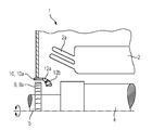
- FIG. 1 shows a cross section through a section of an electrical machine 1.
- the electric machine 1 comprises an axis of rotation 5 about which a rotor 4 is arranged in a known manner so that it rotates the axis of rotation 5 also about the axis of rotation 5, as indicated by the double arrow, rotates.
- the electric machine 1 comprises a stator 2 which, in contrast to the rotating rotor, is fixedly mounted in the electric machine 1.
- rotor 4 and / or stator 2 can preferably be constructed from mutually insulated metal sheets.
- the electric machine 1 according to the present invention further comprises a fan 8, 8a disposed on the rotation axis 5 and the blades thereof extending in the radial direction. The fan 8, 8a promotes a coolant into the interior of the electric machine 1 during operation, that is to say when the rotation axis 5 is rotated.
- FIG. 1 shows only a section of the electrical machine 1.
- the axis of rotation 5 is shown only with one of its end portions (shown on the left in the figure), while the second end portion of the axis of rotation and the further structure to this result in substantially mirror image, which is indicated by the right demolition line.
- the horizontal upper break line is intended to indicate that the electric machine 1 may comprise further components, but these are not required for the understanding of the invention.
- blower 8, 8a shown in FIG. 1 represents a first blower 8 and a second blower 8a, which would be located at the other end section of the rotation axis 5.
- the second blower 8a is optional.
- the electric machine 1 of the present invention comprises a fan guide element 10 which cooperates with the first fan 8. As shown, the fan guide element 10 engages behind the first fan 8 downstream of the first fan 8, whereby the first fan 8 conveys a coolant flow or coolant mass flow from outside the electric machine 1 into the interior.
- the fan guide element 10, 10a may include at least one guide channel 12a, 12b for diverting at least a portion of the coolant flow.
- a first guide channel 12a serves to redirect a first portion of the coolant flow and a second guide channel 12b to redirect a second portion of the coolant flow.
- the fan guide element 10 could also include more than one or two of the guide channels 12a, 12b.
- the guide element 10, 10a shown in Fig. 1 is shown only in a sectional view, but it may be without limitation to a fan guide designed as a Gebläseeitring 10, whereby at desired azimuthal positions suitable portions of the coolant flow (not shown) deflect to selectively targeted individual, especially active components of the electric machine 1 to cool.
- the person skilled in the art will understand that the arrangement of the fan guide elements 8, 8a at different azimuthal positions makes targeted cooling of active components of the electric machine 1 possible.
- the invention provides for the fan guide elements 10, 10a to be designed as adjustable fan guide elements 10, 10a, whereby the portion of the coolant flow which can be deflected by the adjustable fan guide element can be adapted to an operating state of the electrical machine 1.
- a desired component for example the stator head winding 2a
- shifting the boundary between the first guide channel 12a and the second guide channel 12b such that the second guide channel 12b (the lower one in FIG. 1) is reduced, whereas the upper first guide channel 12a increases. That is, in this setting, a greater proportion of the coolant flow is directed to the stator head coils 2a, allowing them to cool more quickly.
- a second fan 8a and a second fan guide element 10a can be attached to the second end section of the rotation axis 5, which in turn are provided with one or more guide channels 12a, 12b.
- the Representations in Figure 1 with respect to the blower 8, and the guide member 10 also representative of a second fan 8a and a second guide member 10a, which may be attached to a second portion of the rotary shaft 5 and a second coolant flow (not shown) in a corresponding manner in the interior the electric machine 1 promotes.
- the deflectable portions of the coolant flow which are diverted by the respective fan guide element 10, 10 a, the deflected portions of the coolant flow are specifically adaptable to an operating state of the electrical machine.
- it may be of interest for example, to cool the rotor 2 and / or the stator 4 during the power consumption of the electrical device 1, while during the coasting of the electric machine 1, ie when no more power is transmitted to the axis of rotation 5 on the drive side , a cooling of the stator windings 2a can be supported by the respective deflected portions of the coolant flow are directed to the stator winding 2a reinforced.
- adjustments of the deflected coolant flow to different load points of the electric machine are possible, that is, operating conditions in which the electric machine is operated at different proportions of the maximum possible load.
- the fan guide element of the invention may be used with both gaseous and liquid coolants.
- gaseous coolants for example, air, purified air and / or hydrogen come into consideration.
- Hydrogen is advantageous in that its heat capacity, and thus its ability to effect effective cooling, is increased.
- the use of hydrogen as coolant requires further safety precautions in order to avoid in particular a blast gas explosion.
- the invention proposed Fan guide or the Gebläseeitelement 10, 10a can be used in connection with liquid coolants, such as water and / or generator oil.
- liquid coolants such as water and / or generator oil.
- these measures are known to the person skilled in the art, so that the dimensioning of a corresponding line system need not be discussed here.
- generator oil as a liquid coolant
- the requirements for special coolant lines can loosen if the generator oil itself is not electrically conductive.
- the fan 8, 8a shown in Figure 1 is shown as a single-stage fan.
- first fan 8 and the first fan guide element 10 also apply to the second fan 8a and a corresponding second fan guide element 10a located at a second, typically second, end portion Rotary axis 5 are located.
- the fan-guide element 10, 10a has been described in connection with a first and second fan-guide element.
- more than two fan guide elements can be used, which are formed either as individual parts or as components of a fan guide ring comprising the plurality of fan guide elements 10, 10a.
Landscapes
- Engineering & Computer Science (AREA)
- Power Engineering (AREA)
- Motor Or Generator Cooling System (AREA)
Priority Applications (6)
| Application Number | Priority Date | Filing Date | Title |
|---|---|---|---|
| EP20130188496 EP2860853A1 (fr) | 2013-10-14 | 2013-10-14 | Elément de guidage de ventilateur pour machine électrique |
| JP2016522784A JP6306169B2 (ja) | 2013-10-14 | 2014-09-12 | 電気機器のためのファン指向部材 |
| US15/027,618 US10116188B2 (en) | 2013-10-14 | 2014-09-12 | Fan directing element for an electric machine |
| PCT/EP2014/069529 WO2015055360A1 (fr) | 2013-10-14 | 2014-09-12 | Élément directeur de ventilation pour machine électrique |
| CN201480056585.7A CN105684275B (zh) | 2013-10-14 | 2014-09-12 | 用于电机的风扇引导元件 |
| EP14766966.7A EP3058642B1 (fr) | 2013-10-14 | 2014-09-12 | Elément de guidage de ventilateur pour machine électrique |
Applications Claiming Priority (1)
| Application Number | Priority Date | Filing Date | Title |
|---|---|---|---|
| EP20130188496 EP2860853A1 (fr) | 2013-10-14 | 2013-10-14 | Elément de guidage de ventilateur pour machine électrique |
Publications (1)
| Publication Number | Publication Date |
|---|---|
| EP2860853A1 true EP2860853A1 (fr) | 2015-04-15 |
Family
ID=49356285
Family Applications (2)
| Application Number | Title | Priority Date | Filing Date |
|---|---|---|---|
| EP20130188496 Withdrawn EP2860853A1 (fr) | 2013-10-14 | 2013-10-14 | Elément de guidage de ventilateur pour machine électrique |
| EP14766966.7A Not-in-force EP3058642B1 (fr) | 2013-10-14 | 2014-09-12 | Elément de guidage de ventilateur pour machine électrique |
Family Applications After (1)
| Application Number | Title | Priority Date | Filing Date |
|---|---|---|---|
| EP14766966.7A Not-in-force EP3058642B1 (fr) | 2013-10-14 | 2014-09-12 | Elément de guidage de ventilateur pour machine électrique |
Country Status (5)
| Country | Link |
|---|---|
| US (1) | US10116188B2 (fr) |
| EP (2) | EP2860853A1 (fr) |
| JP (1) | JP6306169B2 (fr) |
| CN (1) | CN105684275B (fr) |
| WO (1) | WO2015055360A1 (fr) |
Cited By (2)
| Publication number | Priority date | Publication date | Assignee | Title |
|---|---|---|---|---|
| WO2020157464A1 (fr) * | 2019-01-30 | 2020-08-06 | Cummins Generator Technologies Limited | Déflecteur destiné à une machine électrique tournante |
| US11621611B2 (en) | 2019-12-20 | 2023-04-04 | Borgwarner Inc. | Electric machine with baffle member for filtering air flow |
Citations (5)
| Publication number | Priority date | Publication date | Assignee | Title |
|---|---|---|---|---|
| GB1173245A (en) * | 1967-02-03 | 1969-12-03 | Gen Electric | Improvements relating to Dynamo Electric Machines |
| EP0639883A1 (fr) * | 1993-08-17 | 1995-02-22 | ABB Management AG | Machine électrique refroidie par un gaz |
| JPH07250454A (ja) * | 1994-03-09 | 1995-09-26 | Hitachi Ltd | 回転電機 |
| JP2001298906A (ja) * | 2000-04-14 | 2001-10-26 | Toshiba Corp | 回転電機 |
| US20090146512A1 (en) * | 2005-08-31 | 2009-06-11 | Mitsubishi Electric Corporation | Cooling device of electric motor for vehicle |
Family Cites Families (8)
| Publication number | Priority date | Publication date | Assignee | Title |
|---|---|---|---|---|
| US2970233A (en) * | 1958-01-07 | 1961-01-31 | Westinghouse Electric Corp | Ventilating system for a dynamo-electric machine |
| DE4220078A1 (de) * | 1992-06-19 | 1993-12-23 | Bosch Gmbh Robert | Handwerkzeugmaschine |
| US5904471A (en) * | 1996-12-20 | 1999-05-18 | Turbodyne Systems, Inc. | Cooling means for a motor-driven centrifugal air compressor |
| JP2000041362A (ja) | 1998-07-22 | 2000-02-08 | Toshiba Corp | 回転電機 |
| FR2800931B1 (fr) * | 1999-11-09 | 2004-01-23 | Alstom | Dispositif de ventilation et moteur electrique de traction ferroviaire equipe d'un tel dispositif |
| US6700238B1 (en) * | 2002-08-13 | 2004-03-02 | Wei Tong | Generator gas shield and related method |
| DE10261572A1 (de) * | 2002-12-23 | 2004-07-01 | Robert Bosch Gmbh | Elektrohandwerkzeugmaschine |
| CN201985650U (zh) | 2011-01-26 | 2011-09-21 | 无锡东元电机有限公司 | 双馈风力发电机 |
-
2013
- 2013-10-14 EP EP20130188496 patent/EP2860853A1/fr not_active Withdrawn
-
2014
- 2014-09-12 JP JP2016522784A patent/JP6306169B2/ja not_active Expired - Fee Related
- 2014-09-12 WO PCT/EP2014/069529 patent/WO2015055360A1/fr not_active Ceased
- 2014-09-12 EP EP14766966.7A patent/EP3058642B1/fr not_active Not-in-force
- 2014-09-12 CN CN201480056585.7A patent/CN105684275B/zh not_active Expired - Fee Related
- 2014-09-12 US US15/027,618 patent/US10116188B2/en not_active Expired - Fee Related
Patent Citations (5)
| Publication number | Priority date | Publication date | Assignee | Title |
|---|---|---|---|---|
| GB1173245A (en) * | 1967-02-03 | 1969-12-03 | Gen Electric | Improvements relating to Dynamo Electric Machines |
| EP0639883A1 (fr) * | 1993-08-17 | 1995-02-22 | ABB Management AG | Machine électrique refroidie par un gaz |
| JPH07250454A (ja) * | 1994-03-09 | 1995-09-26 | Hitachi Ltd | 回転電機 |
| JP2001298906A (ja) * | 2000-04-14 | 2001-10-26 | Toshiba Corp | 回転電機 |
| US20090146512A1 (en) * | 2005-08-31 | 2009-06-11 | Mitsubishi Electric Corporation | Cooling device of electric motor for vehicle |
Cited By (4)
| Publication number | Priority date | Publication date | Assignee | Title |
|---|---|---|---|---|
| WO2020157464A1 (fr) * | 2019-01-30 | 2020-08-06 | Cummins Generator Technologies Limited | Déflecteur destiné à une machine électrique tournante |
| CN113366742A (zh) * | 2019-01-30 | 2021-09-07 | 康明斯发电机技术有限公司 | 用于旋转电机的导流器 |
| US12160157B2 (en) | 2019-01-30 | 2024-12-03 | Cummins Generator Technologies Limited | Deflector for rotating electrical machine |
| US11621611B2 (en) | 2019-12-20 | 2023-04-04 | Borgwarner Inc. | Electric machine with baffle member for filtering air flow |
Also Published As
| Publication number | Publication date |
|---|---|
| JP6306169B2 (ja) | 2018-04-04 |
| EP3058642B1 (fr) | 2017-11-01 |
| WO2015055360A1 (fr) | 2015-04-23 |
| CN105684275B (zh) | 2019-02-22 |
| JP2016537943A (ja) | 2016-12-01 |
| EP3058642A1 (fr) | 2016-08-24 |
| CN105684275A (zh) | 2016-06-15 |
| US20160254729A1 (en) | 2016-09-01 |
| US10116188B2 (en) | 2018-10-30 |
Similar Documents
| Publication | Publication Date | Title |
|---|---|---|
| EP3405654B1 (fr) | Système de propulsion pour aéronef | |
| EP3501085B1 (fr) | Machine électrique et véhicule équipé de la machine électrique | |
| EP2645544B1 (fr) | Machine électrique dotée d'un refroidissement interne efficace | |
| DE102011056007B4 (de) | Kühlsystem für eine rotierende elektrische Maschine höchster Leistungsdichte | |
| EP2274508B1 (fr) | Système d'échappement de moteur à combustion interne | |
| EP3207616B1 (fr) | Machine électrique rotative avec refroidissement unilatéral et procédé de refroidissement unilatéral | |
| DE102016218741B4 (de) | Elektrische Maschine mit verbesserter Kühlung | |
| EP3476012B1 (fr) | Unité de bague collectrice comprenant un segment d'isolant de ventilateur | |
| EP3017528A2 (fr) | Machine électrique pourvue d'un dispositif thermoconducteur | |
| EP2993767A1 (fr) | Générateur pour une centrale | |
| EP2961009B1 (fr) | Générateur d'éolienne avec un système de bague collectrice | |
| WO2021018343A1 (fr) | Unité d'entraînement électrique, module hybride et ensemble d'entraînement pour véhicule automobile | |
| EP3172128B1 (fr) | Entraînement de nacelle électrique | |
| EP3033825A1 (fr) | Dispositif pour dévier au moins une partie d'un fluide de refroidissement circulant axialement dans un espace intermédiaire situé entre un rotor et un stator d'une machine électrique tournante | |
| DE102012220559A1 (de) | Kühlung für elektrische Generatoren | |
| EP3058642B1 (fr) | Elément de guidage de ventilateur pour machine électrique | |
| DE102004049795A1 (de) | Kühlvorrichtung für eine mit einer Kühlflüssigkeit kühlbaren elektrischen Maschine | |
| DE102012209549A1 (de) | Kühlmittelüberbrückungsleitung für eine Gasturbine | |
| EP2993766A1 (fr) | Refroidissement amélioré d'un moteur annulaire | |
| EP3732772B1 (fr) | Unité de bague collectrice pourvue de système de refroidissement actif | |
| DE20317814U1 (de) | Elektromotor | |
| WO2010025986A2 (fr) | Machine dynamoélectrique à système de refroidissement | |
| EP2911276A1 (fr) | Circuit de refroidissement comprenant au moins deux fluides de refroidissement pour machine électrique | |
| EP4008048B1 (fr) | Arbre d'entraînement d'une machine dynamoélectrique et son procédé de fabrication | |
| EP1122865B1 (fr) | Agencement de machine électrique tournante avec machine électrique tournante et dispositif de refroidissement |
Legal Events
| Date | Code | Title | Description |
|---|---|---|---|
| PUAI | Public reference made under article 153(3) epc to a published international application that has entered the european phase |
Free format text: ORIGINAL CODE: 0009012 |
|
| 17P | Request for examination filed |
Effective date: 20131014 |
|
| AK | Designated contracting states |
Kind code of ref document: A1 Designated state(s): AL AT BE BG CH CY CZ DE DK EE ES FI FR GB GR HR HU IE IS IT LI LT LU LV MC MK MT NL NO PL PT RO RS SE SI SK SM TR |
|
| AX | Request for extension of the european patent |
Extension state: BA ME |
|
| STAA | Information on the status of an ep patent application or granted ep patent |
Free format text: STATUS: THE APPLICATION IS DEEMED TO BE WITHDRAWN |
|
| 18D | Application deemed to be withdrawn |
Effective date: 20151016 |