EP2861118B1 - Ensemble sanitaire - Google Patents
Ensemble sanitaire Download PDFInfo
- Publication number
- EP2861118B1 EP2861118B1 EP13714842.5A EP13714842A EP2861118B1 EP 2861118 B1 EP2861118 B1 EP 2861118B1 EP 13714842 A EP13714842 A EP 13714842A EP 2861118 B1 EP2861118 B1 EP 2861118B1
- Authority
- EP
- European Patent Office
- Prior art keywords
- magnets
- toilet bowl
- lid
- toilet
- magnetic
- Prior art date
- Legal status (The legal status is an assumption and is not a legal conclusion. Google has not performed a legal analysis and makes no representation as to the accuracy of the status listed.)
- Active
Links
Images





Classifications
-
- A—HUMAN NECESSITIES
- A47—FURNITURE; DOMESTIC ARTICLES OR APPLIANCES; COFFEE MILLS; SPICE MILLS; SUCTION CLEANERS IN GENERAL
- A47K—SANITARY EQUIPMENT; ACCESSORIES THEREFOR, e.g. TOILET ACCESSORIES
- A47K13/00—Seats or covers for all kinds of closets
- A47K13/24—Parts or details not covered in, or of interest apart from, groups A47K13/02 - A47K13/22
- A47K13/26—Mounting devices for seats or covers
-
- A—HUMAN NECESSITIES
- A47—FURNITURE; DOMESTIC ARTICLES OR APPLIANCES; COFFEE MILLS; SPICE MILLS; SUCTION CLEANERS IN GENERAL
- A47K—SANITARY EQUIPMENT; ACCESSORIES THEREFOR, e.g. TOILET ACCESSORIES
- A47K13/00—Seats or covers for all kinds of closets
- A47K13/12—Hinges
-
- E—FIXED CONSTRUCTIONS
- E05—LOCKS; KEYS; WINDOW OR DOOR FITTINGS; SAFES
- E05D—HINGES OR SUSPENSION DEVICES FOR DOORS, WINDOWS OR WINGS
- E05D1/00—Pinless hinges; Substitutes for hinges
- E05D1/06—Pinless hinges; Substitutes for hinges consisting of two easily-separable parts
-
- E—FIXED CONSTRUCTIONS
- E05—LOCKS; KEYS; WINDOW OR DOOR FITTINGS; SAFES
- E05Y—INDEXING SCHEME ASSOCIATED WITH SUBCLASSES E05D AND E05F, RELATING TO CONSTRUCTION ELEMENTS, ELECTRIC CONTROL, POWER SUPPLY, POWER SIGNAL OR TRANSMISSION, USER INTERFACES, MOUNTING OR COUPLING, DETAILS, ACCESSORIES, AUXILIARY OPERATIONS NOT OTHERWISE PROVIDED FOR, APPLICATION THEREOF
- E05Y2201/00—Constructional elements; Accessories therefor
- E05Y2201/40—Motors; Magnets; Springs; Weights; Accessories therefor
- E05Y2201/46—Magnets
-
- E—FIXED CONSTRUCTIONS
- E05—LOCKS; KEYS; WINDOW OR DOOR FITTINGS; SAFES
- E05Y—INDEXING SCHEME ASSOCIATED WITH SUBCLASSES E05D AND E05F, RELATING TO CONSTRUCTION ELEMENTS, ELECTRIC CONTROL, POWER SUPPLY, POWER SIGNAL OR TRANSMISSION, USER INTERFACES, MOUNTING OR COUPLING, DETAILS, ACCESSORIES, AUXILIARY OPERATIONS NOT OTHERWISE PROVIDED FOR, APPLICATION THEREOF
- E05Y2999/00—Subject-matter not otherwise provided for in this subclass
Definitions
- the technical concept involves a sanitary set that consists of a toilet seat and a lid placed on the toilet bowl where the toilet seat and toilet lid are connected to the upper part of a toilet bowl by means of rotary joints around the horizontal axis.
- Hinges are fixed in its position by screws coming through the holes in the horizontal part of the toilet bowl.
- the lid and the toilet seat can be raised from or lowered towards the toilet bowl by the means of these hinges.
- This system doesn't allow the lid and the toilet seat to be removed from and attached back to the toilet bowl, for example in the case of cleaning the sanitary set.
- Scale and dirtiness settle easily on the setup consisting of hinges, fixation screws, covers and female screws as the sanitary set is being used, which after some time can limit the functionality of the system of hinges, i.e. it can be impossible to disassemble the lid or the toilet seat from the toilet bowl, when the lid or the toilet seat needs to be replaced.
- This system of fixation of the parts of the sanitary set doesn't allow for easy and hygienically perfect maintenance.
- the system known from the background arts contains many inner spaces and gaps that cannot be cleaned during the common maintenance process.
- the aim of presented invention is therefore to find such way of connecting the parts of sanitary set consisting of the toilet seat, the lid and the toilet bowl, without the need for permanent fixation by means of hinges in order to provide the possibility to easily remove the toilet seat and the lid separately from the toilet bowl and to attach above mentioned parts back to previously allotted position on the toilet bowl by mere movement of the part further from the bowl or movement closer to the bowl.
- US-A-2009/064402 discloses a sanitary set according to the preamble of claim 1.
- magnets are arranged in the bar constituted from the tube from nonmagnetic material.
- the bar can be fixed on the upper edge of the toilet bowl by means of fixtures and fixing components that go through the holes in the toilet bowl. Above mentioned fixing components, in most cases screws can go through the vertical assembly holes in rear edge of ordinary toilet bowl.
- the bar is completely integrated in the upper part of newly designed toilet bowl.
- at least one magnet is composed from partial magnets. These partial magnets are arranged towards each other with changing magnetic polarity N, S in axial direction, in other word the partial magnets are fitted toward each other by repulsing magnetic poles. It is advantageous to insert ferromagnetic inserts between partial magnets described above.
- the presented invention includes the solution, where the rolling joints connecting individual parts of the sanitary sets are constructed as general rolling surfaces or as sectors of these general rolling surfaces. Mutual attracting magnetic force is therefore variable as the parts are rotated. At a given moment of the rotation movement, individual parts of the sanitary set are connected together by magnetic force acting in the radial direction that is perpendicular to the plane of the connection as well as in the axial direction that is parallel to the plane of connection.
- general rolling surface is used at least on one part of the sanitary set, the tangential action of magnetic force is added to the radial and axial magnetic force action, while this tangential magnetic force shoes its minimums and maximums according to the topology of the general rolling surface.
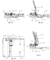
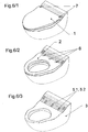
- the sanitary set according to the first embodiment of the invention that is showed in the figs. 1/1 to 1/4 is adjusted on the common toilet bowl 3 , by the common toilet bowl is meant such toilet bowl that is equipped with vertical holes 9 in the rear edge of the bowl and positioned approximately in the plane of the sanitary set, vertical holes are used for inserting mounting members, such as screws, in order to mount the sanitary set to the bowl.
- This sanitary set consists of the toilet seat 2 and the lid 1 . which in the fig. 1/1 are laying one on another and on the toilet bowl 3 .
- the toilet seat 2 and the lid 1 c an be lifted from the toilet bowl 3 as shown in the fig. 1/2 or 1/3 .
- Novelty of this solution lies in the design of the revolving mounting of the toilet seat 2 and the lid 1 in relation to the toilet bowl 3 .
- the horizontal bar 5 Above the rear upper edge of the toilet bowl 3 the horizontal bar 5 is mounted by means of above mentioned mounting members 9 , that constitutes of the tube made of nonmagnetic material, in which the first magnets 5.1 , 5.2 are arranged.
- the rear edges of the toilet seat 2 and the lid 1 , in which the second magnets 6 are arranged in appropriate placement, are rolling on the outer perimeter of the horizontal bar 5 .
- the sanitary set according to the second embodiment of the invention that is showed in the figs. 2/1. to 2/5 . differs from the first embodiment by raised fixture 4 of the bar 5 .
- the sanitary set according to the third embodiment of the invention that is showed in the figs. 3/1. to 3/5 . differs from previous embodiments by the fixture 4 that is formed in the shape of flat slat that has the bar 5 integrated in its upper side and consists of first magnets 5.1 and 5.2 and having double channels in which the second magnets 6 of the toilet seat 2 respectively the third magnets 7 of the lid 1 are rolling.
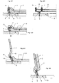
- the sanitary set according to the fourth embodiment of the invention that is shown in the figs. 4/1. to 4/5 . is designated to be used with common toilet bowl 3 , differs from the previous embodiments by the bar 5 that is in positioned further back on the toilet bowl 3 .
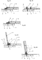
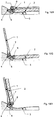
- FIG. 10/1. to 10/3 there are side cross section views of the fifth embodiment of the sanitary set for the special toilet bowl 3 in different positions of the parts of sanitary set.
- the bar 5 is in this embodiment partly imbedded in the fixture 4 that is integrated in the toilet bowl 3 .
- On the upper side of the fixture 4 longitudinal depressions along the sides of the bar 5 are formed in which the rear edges of the lid 1 and the toilet seat 2 fit.
- FIG. 11/1 to 11/3 there are side cross section views of the sixth embodiment of the sanitary set for the special toilet bowl 3 in different positions of the parts of the sanitary set.
- the bar 5 is shaped as a pair of parallel flat slats that are imbedded in the toilet bowl 3 .
- the lid 1 and the toilet seat 2 are each connected to its own bar 5 and their rear edges and are revolving on these bars 5 .
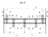
- each magnet 5.1 , 5.2 , 7 , 6 consists of at least two partial magnets that are arranged towards each other axially, directly or indirectly through the ferromagnetic insert 10 , by accordant magnetic poles.
- magnets are arranged by polarity in pattern NS-SN-NS or vice versa.
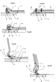
- fig 14 there is side section view of the seventh embodiment of sanitary set that implements the general rolling surface 11 on at least one part, i.e. on the toilet seat 2 , the lid 1 or the toilet bowl 3 , in order to achieve the tangential acting of magnetic force during the movement of the parts.
- the sanitary set according to the presented invention solves mutual connection of three parts of the set : the toilet seat 2 , the lid 1 , the toilet bowl 3 without the need for permanent mounting and uses the attracting magnetic force acting in sets of magnetic rolling joints in the way that the toilet seat 2 in which the second magnet 6 is inserted is connected to the horizontal part of toilet bowl 3 in which the first magnet 5.1 , 5.2. is inserted into the integrated bar 5 .
- the lid 1 in which the third magnet 7 is inserted is connected to the horizontal part of the toilet bowl 3 in which the first magnet 5.1 , 5.2. is inserted into the integrated bar 5 .
- the sanitary set according to the presented invention includes the technical solution, where the means of rolling magnetic joints of the toilet bowl 3 , such as magnets 5.1 , 5.2 , are firmly integrated to horizontal part of toilet bowl 3 in such way that they form the shape of the horizontal surface that in the place where magnets 5.1 , 5.2 forms the rolling surface of the joints.
- the second possible solution is the embodiment, where magnets 5.1 , 5.2 of the toilet bowl 3 are integrated to the surface of the toilet bowl 3 that is formed from for example from round tube. This tube is integral part of the toilet bowl 3 and forms the rolling surface and is positioned and fixated to the toilet bowl 3 on the upper horizontal part of the bowl.
- the toilet seat 2 as well as the lid 1 has the according magnets 6,7 , of the joint integrated in the rear end of the toilet seat 2 or the lid 1 respectively.
- the material of these parts creates the surface of the magnets 6,7 , and forms the rolling surfaces of the joints.
- the rolling surfaces of the magnets in magnetic joints can be formed as cylindrical rolling surfaces or general rolling surfaces 11 .
- Effective rolling surface can also be formed as a sector of the general rolling surface 11 .
- Mutual attracting magnetic force is therefore variable as the parts are rotated.
- individual parts of the sanitary set namely the lid 1 , the toilet seat 2 and the toilet bowl 3 , are connected together by magnetic force acting in the radial direction that is perpendicular to the plane of the connection as well as in the axial direction, that is parallel to the plane of connection.
- the presented invention takes in account that at least one from the pair of the related components in the magnetic joint must be from magnetic active material, such as permanent magnet or electromagnet.
- the second component from the pair of components creating the magnetic joint can also be formed from magnetic active material such as permanent magnet of electromagnet, or it can be formed from magnetic reactive material, such as ferromagnetic steel or another material that can be attracted by magnetic force.
- magnetic active material such as permanent magnet of electromagnet
- magnetic reactive material such as ferromagnetic steel or another material that can be attracted by magnetic force.
- the second solution mentioned above can be suitable regarding the manufacturing costs of the sanitary set.
- Both related components in the magnetic joint are positioned toward each other in precisely defined positions.
- the ferromagnetic inserts can be placed at the sides of magnets in the magnetic joints to alter the magnetic field and the strength of the magnetic joints.
- magnets are situated toward each other in axial direction in opposite polarization.
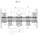
- the attracting force of the magnets in joints is substantially increased by technical solution shown in the fig. 13 ., in which at least one magnet of the joint is composed from partial magnets
- These partial magnets are arranged towards each other with changing magnetic polarity N,S in axial direction, in other word the partial magnets are fitted toward each other by repulsing magnetic poles. It is advantageous to insert ferromagnetic inserts between partial magnets described above.
- the magnetic rolling joint according to the invention as illustrated in the fig 13 .
- at least one magnet from the pair of the related components in the magnetic joint consists of arrangement of partial magnets, allows the attractive force in the joints to be increased.
- These partial magnets are arranged towards each other with changing magnetic polarity N,S in axial direction, in other word the partial magnets are fitted toward each other by repulsing magnetic poles.
- the presented invention takes in account that at least one magnet from the pair of related components in magnetic joint can be formed from arrangement of at least two partial magnets, however, when it is desirable, the both related magnet from the pair can be replaced by the above described arrangement.
- the research and experiments that were conducted in regard to the presented invention have shown, that the magnetic joints made up only from simple magnets, or arrangements of partial magnets that are attracting each other are not efficient from the view of magnetic force.
- the best technical solution regarding the magnetic force optimization is to use the arrangements of partial magnets.
- the magnetic field is forced above the ferromagnetic insert 10 to form the best and strongest magnetic interaction with other component in the magnetic rolling joint when the above described solution is used.
- the thickness of ferromagnetic inserts was selected from the range 0 mm to 8,3 mm.
- the magnetic attracting force is nearly of the same strength for ferromagnetic inserts of thickness 3 - 8 mm.
- the mutual magnetic attracting force and it's strength among two parts of magnetic joint is made as a combination of magnetic induction in the space between the parts and the area of magnetic action, the final strength of the joint is to some extent independent on the thickness of ferromagnetic inserts 10 used.
- the best mode of the invention where the magnetic strength of the joint is optimal regarding strength/cost ratio, is when ferromagnetic inserts 10 of thickness 5 mm and more are used between a pair of partial magnets in at least one component from the pair that constitutes a magnetic rolling joint.
- Sanitary set according to the presented invention bring several major advantages to commonly known technical solutions :
- the toilet seat 2 and the lid 1 can be removed from and attached back by mere movement apart and back in relation to the toilet bowl 3 without need for permanent assembly and this process can be repeated without causing any wear out. All parts of the set have simple and smooth surface allowing for easy and hygienically perfect maintenance.
- the toilet seat 2 and the lid 1 can be removed from the toilet bowl and can be cleaned and sterilized separately.
- the horizontal plane of the toilet bowl 3 is smooth and it can be maintenanced easily when the toilet seat 2 and the lid 1 are removed.
- the lid 1 and the toilet seat 2 is held in upright position by the maximum of the tangential magnetic force in the magnetic joint. This position in independent of any other backing and therefore the lid 1 or the toilet seat 2 doesn't have to lean against the wall or back side of the toilet set to sustain the upright position.
- the rolling magnetic joint used in the presented sanitary set forms a strong, permanent and reusable connection among the parts and it works well in humid environments without any wear out or corrosion.
- the sanitary set according to the presented invention can be applied in many situations. It can be used for any cases, where there is a need for new toilet facility with improved functionality or it can be used as an upgrade for current toilet facilities.
- the presented invention can be used in household environments as well as in public or commercial spaces.
- the presented invention is particularly effective wherever it is highly important to sustain high level of sanitation of the toilet facilities and where the sanitary sets need to be cleaned frequently, simply and effectively. It is possible to clean and sterilize the lids 1 and the toilet seats 2 externally in sterilization boxes.
- the presented invention can be used well in regards with above mentioned features in hospitals, spa facilities, sport centers, gyms, retirement houses, hotels, etc. In public spaces, it is possible to use electromagnets in the magnetic joints to prevent undesired removal of the toilet seats 2 and lids 1 .
Landscapes
- Health & Medical Sciences (AREA)
- Public Health (AREA)
- Engineering & Computer Science (AREA)
- Mechanical Engineering (AREA)
- Toilet Supplies (AREA)
- Non-Flushing Toilets (AREA)
- Sanitary Device For Flush Toilet (AREA)
Claims (3)
- Ensemble sanitaire consistant en une lunette (2) des toilettes, un couvercle (1) et une cuvette (3) des toilettes, où la lunette (2) des toilettes et le couvercle (1) sont placés sur la cuvette (3) des toilettes et reliés au bord supérieur de la cuvette (3) des toilettes au moyen de joints de roulement autour d'un axe horizontale, où les joints de roulement sont constitués d'aimants (5.1, 5.2) disposés sur ou dans une barre (5) horizontale à l'extrémité arrière du plan supérieur de la cuvette (3) des toilettes, d'aimants (6) inversement polarisés à l'extrémité arrière de la lunette (2) des toilettes et d'aimants (7) inversement polarisés à l'extrémité arrière du couvercle (1), caractérisé en ce qu'au moins un desdits aimants (5.1, 5.2, 6, 7) consiste en agencement d'aimants partiels disposés l'un envers l'autre, où la polarité magnétique N,S altère en direction axiale, qui sont par conséquent disposés l'un envers l'autre avec des pôles magnétiques repoussants.
- Ensemble sanitaire selon la revendication 2, caractérisé en ce qu'une semelle (10) ferromagnétique est insérée entre les aimants partiels ou est disposée sur les côtés desdits aimants.
- Ensemble sanitaire selon la revendication 1 à 2, caractérisé en ce qu'au moins un joint de roulement de l'ensemble est construit comme une surface (10) de roulement générale ou une section de ladite surface.
Priority Applications (3)
| Application Number | Priority Date | Filing Date | Title |
|---|---|---|---|
| PL13714842T PL2861118T3 (pl) | 2012-06-18 | 2013-02-21 | Zestaw sanitarny |
| RS20180835A RS57584B1 (sr) | 2012-06-18 | 2013-02-21 | Sanitarni komplet |
| SM20180383T SMT201800383T1 (it) | 2012-06-18 | 2013-02-21 | Apparecchio sanitario |
Applications Claiming Priority (2)
| Application Number | Priority Date | Filing Date | Title |
|---|---|---|---|
| CZ201226237U CZ25067U1 (cs) | 2012-06-18 | 2012-06-18 | Sanitární souprava |
| PCT/CZ2013/000020 WO2013189469A2 (fr) | 2012-06-18 | 2013-02-21 | Ensemble sanitaire |
Publications (3)
| Publication Number | Publication Date |
|---|---|
| EP2861118A2 EP2861118A2 (fr) | 2015-04-22 |
| EP2861118B1 true EP2861118B1 (fr) | 2018-05-02 |
| EP2861118B8 EP2861118B8 (fr) | 2018-08-29 |
Family
ID=47901672
Family Applications (1)
| Application Number | Title | Priority Date | Filing Date |
|---|---|---|---|
| EP13714842.5A Active EP2861118B8 (fr) | 2012-06-18 | 2013-02-21 | Ensemble sanitaire |
Country Status (16)
| Country | Link |
|---|---|
| US (1) | US10143342B2 (fr) |
| EP (1) | EP2861118B8 (fr) |
| CY (1) | CY1120537T1 (fr) |
| CZ (1) | CZ25067U1 (fr) |
| DK (1) | DK2861118T3 (fr) |
| EA (1) | EA030567B9 (fr) |
| ES (1) | ES2680150T3 (fr) |
| HR (1) | HRP20181120T1 (fr) |
| HU (1) | HUE039538T2 (fr) |
| LT (1) | LT2861118T (fr) |
| PL (1) | PL2861118T3 (fr) |
| PT (1) | PT2861118T (fr) |
| RS (1) | RS57584B1 (fr) |
| SI (1) | SI2861118T1 (fr) |
| SM (1) | SMT201800383T1 (fr) |
| WO (1) | WO2013189469A2 (fr) |
Families Citing this family (5)
| Publication number | Priority date | Publication date | Assignee | Title |
|---|---|---|---|---|
| CZ29913U1 (cs) * | 2015-09-22 | 2016-10-31 | Rawa Design S.R.O. | Sanitární souprava s brzděným sklápěním |
| CZ2015653A3 (cs) * | 2015-09-22 | 2017-04-19 | Rawa Design S.R.O. | Magnetický spoj |
| DE102017105204B4 (de) * | 2016-03-17 | 2023-10-12 | Hamberger Industriewerke Gmbh | WC-Sitzgarnitur und Urinaldeckel |
| US10912431B2 (en) * | 2018-07-10 | 2021-02-09 | Kohler Co. | Hinge assembly for toilet |
| TR202021908A1 (tr) * | 2020-12-28 | 2022-07-21 | Eczacibasi Yapi Gerecleri Sanayi Ve Ticaret Anonim Sirketi | Takoz etki̇si̇ni̇n manyeti̇k olarak oluşturulduğu klozet kapaği takimi |
Family Cites Families (7)
| Publication number | Priority date | Publication date | Assignee | Title |
|---|---|---|---|---|
| US4561130A (en) | 1984-06-05 | 1985-12-31 | Dewey Bumgardner | Toilet seat cover safety latch |
| FR2898033B1 (fr) * | 2006-03-02 | 2010-07-30 | Daniel Mauduit | Toilettes a palier et tourillon munis de moyens d'attraction magnetique |
| FR2908028B1 (fr) * | 2006-11-06 | 2008-12-26 | Daniel Mauduit | Motorisation d'abattant de wc par un dispositif magnetique |
| US7932646B2 (en) * | 2007-01-15 | 2011-04-26 | Canon Kabushiki Kaisha | Exposure apparatus with a stage, driving unit,and force applying unit having a separate magnetic shield |
| FR2915667A1 (fr) * | 2007-05-04 | 2008-11-07 | Daniel Mauduit | Dispositif de frein de chute pour abattant a charniere magnetique. |
| US7817006B2 (en) * | 2008-05-20 | 2010-10-19 | Cedar Ridge Research, Llc. | Apparatuses and methods relating to precision attachments between first and second components |
| JP5397258B2 (ja) * | 2010-02-16 | 2014-01-22 | 株式会社Lixil | 便器上面設備 |
-
2012
- 2012-06-18 CZ CZ201226237U patent/CZ25067U1/cs not_active IP Right Cessation
-
2013
- 2013-02-21 SM SM20180383T patent/SMT201800383T1/it unknown
- 2013-02-21 ES ES13714842.5T patent/ES2680150T3/es active Active
- 2013-02-21 WO PCT/CZ2013/000020 patent/WO2013189469A2/fr not_active Ceased
- 2013-02-21 RS RS20180835A patent/RS57584B1/sr unknown
- 2013-02-21 DK DK13714842.5T patent/DK2861118T3/en active
- 2013-02-21 US US14/409,247 patent/US10143342B2/en active Active
- 2013-02-21 EP EP13714842.5A patent/EP2861118B8/fr active Active
- 2013-02-21 HU HUE13714842A patent/HUE039538T2/hu unknown
- 2013-02-21 LT LTEP13714842.5T patent/LT2861118T/lt unknown
- 2013-02-21 EA EA201492141A patent/EA030567B9/ru not_active IP Right Cessation
- 2013-02-21 HR HRP20181120TT patent/HRP20181120T1/hr unknown
- 2013-02-21 SI SI201331105T patent/SI2861118T1/en unknown
- 2013-02-21 PL PL13714842T patent/PL2861118T3/pl unknown
- 2013-02-21 PT PT137148425T patent/PT2861118T/pt unknown
-
2018
- 2018-08-01 CY CY20181100801T patent/CY1120537T1/el unknown
Non-Patent Citations (1)
| Title |
|---|
| None * |
Also Published As
| Publication number | Publication date |
|---|---|
| LT2861118T (lt) | 2018-08-10 |
| ES2680150T3 (es) | 2018-09-04 |
| PL2861118T3 (pl) | 2018-11-30 |
| RS57584B1 (sr) | 2018-11-30 |
| EA030567B1 (ru) | 2018-08-31 |
| DK2861118T3 (en) | 2018-08-06 |
| HRP20181120T1 (hr) | 2018-09-21 |
| HUE039538T2 (hu) | 2019-01-28 |
| EA030567B9 (ru) | 2018-10-31 |
| SMT201800383T1 (it) | 2018-09-13 |
| PT2861118T (pt) | 2018-07-25 |
| EA201492141A1 (ru) | 2015-06-30 |
| EP2861118A2 (fr) | 2015-04-22 |
| US20150190019A1 (en) | 2015-07-09 |
| CY1120537T1 (el) | 2019-07-10 |
| WO2013189469A3 (fr) | 2014-02-13 |
| CZ25067U1 (cs) | 2013-03-14 |
| WO2013189469A2 (fr) | 2013-12-27 |
| EP2861118B8 (fr) | 2018-08-29 |
| ES2680150T8 (es) | 2018-09-13 |
| SI2861118T1 (en) | 2018-08-31 |
| US10143342B2 (en) | 2018-12-04 |
Similar Documents
| Publication | Publication Date | Title |
|---|---|---|
| EP2861118B1 (fr) | Ensemble sanitaire | |
| USD675453S1 (en) | Furniture set consisting of modular elements | |
| USD940494S1 (en) | Water filter jug | |
| JP4347436B2 (ja) | 自己調節型支持機構 | |
| USD609482S1 (en) | Seating furniture | |
| USD889940S1 (en) | Support chair for poured concrete reinforcement members | |
| USD636278S1 (en) | Timer for two way solenoid valve | |
| USD656585S1 (en) | Faucet | |
| USD604100S1 (en) | Mini donut grill plate | |
| EP2088908A1 (fr) | Porte-torchons | |
| USD896928S1 (en) | Urinal or toilet mat | |
| USD642343S1 (en) | Floor cleaning machine | |
| USD865122S1 (en) | Faucet | |
| USD857171S1 (en) | Faucet | |
| USD653481S1 (en) | Chair part | |
| WO2012152909A1 (fr) | Rail de guidage coulissant | |
| CA2662300A1 (fr) | Ensemble d'allege magnetique | |
| USD679370S1 (en) | Bath seat for babies | |
| USD712102S1 (en) | Carpet cleaning machine | |
| USD805368S1 (en) | Magnetic drawer lock | |
| EP3139793A1 (fr) | Élément de raccordement servant à raccorder un corps, pouvant être fixé au mur, à un support mural | |
| JP5397258B2 (ja) | 便器上面設備 | |
| USD626754S1 (en) | Hanger assembly for supporting undergarments | |
| USD673251S1 (en) | Sanitary appliance | |
| CZ25013U1 (cs) | Sanitární souprava |
Legal Events
| Date | Code | Title | Description |
|---|---|---|---|
| PUAI | Public reference made under article 153(3) epc to a published international application that has entered the european phase |
Free format text: ORIGINAL CODE: 0009012 |
|
| 17P | Request for examination filed |
Effective date: 20150115 |
|
| AK | Designated contracting states |
Kind code of ref document: A2 Designated state(s): AL AT BE BG CH CY CZ DE DK EE ES FI FR GB GR HR HU IE IS IT LI LT LU LV MC MK MT NL NO PL PT RO RS SE SI SK SM TR |
|
| AX | Request for extension of the european patent |
Extension state: BA ME |
|
| DAX | Request for extension of the european patent (deleted) | ||
| RAP1 | Party data changed (applicant data changed or rights of an application transferred) |
Owner name: RAWA DESIGN S.R.O |
|
| 17Q | First examination report despatched |
Effective date: 20160817 |
|
| GRAP | Despatch of communication of intention to grant a patent |
Free format text: ORIGINAL CODE: EPIDOSNIGR1 |
|
| INTG | Intention to grant announced |
Effective date: 20170908 |
|
| GRAS | Grant fee paid |
Free format text: ORIGINAL CODE: EPIDOSNIGR3 |
|
| GRAA | (expected) grant |
Free format text: ORIGINAL CODE: 0009210 |
|
| RAP1 | Party data changed (applicant data changed or rights of an application transferred) |
Owner name: MAGNETIN TO.A.S. |
|
| AK | Designated contracting states |
Kind code of ref document: B1 Designated state(s): AL AT BE BG CH CY CZ DE DK EE ES FI FR GB GR HR HU IE IS IT LI LT LU LV MC MK MT NL NO PL PT RO RS SE SI SK SM TR |
|
| REG | Reference to a national code |
Ref country code: GB Ref legal event code: FG4D |
|
| REG | Reference to a national code |
Ref country code: AT Ref legal event code: REF Ref document number: 994358 Country of ref document: AT Kind code of ref document: T Effective date: 20180515 Ref country code: CH Ref legal event code: EP |
|
| REG | Reference to a national code |
Ref country code: DE Ref legal event code: R096 Ref document number: 602013036859 Country of ref document: DE Ref country code: IE Ref legal event code: FG4D |
|
| REG | Reference to a national code |
Ref country code: DE Ref legal event code: R096 Ref document number: 602013036859 Country of ref document: DE |
|
| RAP2 | Party data changed (patent owner data changed or rights of a patent transferred) |
Owner name: MAGNETIN TO.A.S. |
|
| REG | Reference to a national code |
Ref country code: HR Ref legal event code: TUEP Ref document number: P20181120 Country of ref document: HR |
|
| REG | Reference to a national code |
Ref country code: RO Ref legal event code: EPE |
|
| REG | Reference to a national code |
Ref country code: PT Ref legal event code: SC4A Ref document number: 2861118 Country of ref document: PT Date of ref document: 20180725 Kind code of ref document: T Free format text: AVAILABILITY OF NATIONAL TRANSLATION Effective date: 20180719 |
|
| REG | Reference to a national code |
Ref country code: CH Ref legal event code: NV Representative=s name: TR-IP CONSULTING LLC, CH |
|
| RIN2 | Information on inventor provided after grant (corrected) |
Inventor name: RAWOVA, NADEZDA Inventor name: PAKOSTA, HYNEK |
|
| REG | Reference to a national code |
Ref country code: DK Ref legal event code: T3 Effective date: 20180730 |
|
| REG | Reference to a national code |
Ref country code: SE Ref legal event code: TRGR |
|
| REG | Reference to a national code |
Ref country code: NL Ref legal event code: FP |
|
| REG | Reference to a national code |
Ref country code: CH Ref legal event code: PK Free format text: BERICHTIGUNG B8 |
|
| REG | Reference to a national code |
Ref country code: ES Ref legal event code: FG2A Ref document number: 2680150 Country of ref document: ES Kind code of ref document: T3 Effective date: 20180904 |
|
| REG | Reference to a national code |
Ref country code: EE Ref legal event code: FG4A Ref document number: 015749 Country of ref document: EE Effective date: 20180724 |
|
| REG | Reference to a national code |
Ref country code: HR Ref legal event code: T1PR Ref document number: P20181120 Country of ref document: HR |
|
| REG | Reference to a national code |
Ref country code: NO Ref legal event code: T2 Effective date: 20180502 |
|
| REG | Reference to a national code |
Ref country code: SK Ref legal event code: T3 Ref document number: E 28055 Country of ref document: SK |
|
| REG | Reference to a national code |
Ref country code: GR Ref legal event code: EP Ref document number: 20180402042 Country of ref document: GR Effective date: 20190109 |
|
| REG | Reference to a national code |
Ref country code: HU Ref legal event code: AG4A Ref document number: E039538 Country of ref document: HU |
|
| REG | Reference to a national code |
Ref country code: DE Ref legal event code: R097 Ref document number: 602013036859 Country of ref document: DE |
|
| REG | Reference to a national code |
Ref country code: HR Ref legal event code: ODRP Ref document number: P20181120 Country of ref document: HR Payment date: 20190201 Year of fee payment: 7 |
|
| PLBE | No opposition filed within time limit |
Free format text: ORIGINAL CODE: 0009261 |
|
| STAA | Information on the status of an ep patent application or granted ep patent |
Free format text: STATUS: NO OPPOSITION FILED WITHIN TIME LIMIT |
|
| 26N | No opposition filed |
Effective date: 20190205 |
|
| REG | Reference to a national code |
Ref country code: CH Ref legal event code: PCAR Free format text: NEW ADDRESS: ROUTE DU COUTSET 18, 1485 NUVILLY (CH) |
|
| REG | Reference to a national code |
Ref country code: HR Ref legal event code: ODRP Ref document number: P20181120 Country of ref document: HR Payment date: 20200217 Year of fee payment: 8 |
|
| REG | Reference to a national code |
Ref country code: HR Ref legal event code: ODRP Ref document number: P20181120 Country of ref document: HR Payment date: 20210810 Year of fee payment: 9 |
|
| REG | Reference to a national code |
Ref country code: AT Ref legal event code: UEP Ref document number: 994358 Country of ref document: AT Kind code of ref document: T Effective date: 20180502 |
|
| REG | Reference to a national code |
Ref country code: HR Ref legal event code: ODRP Ref document number: P20181120 Country of ref document: HR Payment date: 20220216 Year of fee payment: 10 |
|
| PGFP | Annual fee paid to national office [announced via postgrant information from national office to epo] |
Ref country code: RS Payment date: 20220217 Year of fee payment: 10 Ref country code: LT Payment date: 20220215 Year of fee payment: 10 Ref country code: IE Payment date: 20220217 Year of fee payment: 10 Ref country code: HU Payment date: 20220214 Year of fee payment: 10 Ref country code: FI Payment date: 20220216 Year of fee payment: 10 Ref country code: BG Payment date: 20220215 Year of fee payment: 10 |
|
| PGFP | Annual fee paid to national office [announced via postgrant information from national office to epo] |
Ref country code: IS Payment date: 20220215 Year of fee payment: 10 Ref country code: SM Payment date: 20220221 Year of fee payment: 10 Ref country code: SE Payment date: 20220218 Year of fee payment: 10 Ref country code: NO Payment date: 20220223 Year of fee payment: 10 Ref country code: MT Payment date: 20220215 Year of fee payment: 10 Ref country code: MK Payment date: 20220208 Year of fee payment: 10 Ref country code: MC Payment date: 20220216 Year of fee payment: 10 Ref country code: LV Payment date: 20220215 Year of fee payment: 10 Ref country code: LU Payment date: 20220218 Year of fee payment: 10 Ref country code: HR Payment date: 20220216 Year of fee payment: 10 Ref country code: GR Payment date: 20220215 Year of fee payment: 10 Ref country code: EE Payment date: 20220215 Year of fee payment: 10 |
|
| PGFP | Annual fee paid to national office [announced via postgrant information from national office to epo] |
Ref country code: SI Payment date: 20220215 Year of fee payment: 10 |
|
| PGFP | Annual fee paid to national office [announced via postgrant information from national office to epo] |
Ref country code: CY Payment date: 20220209 Year of fee payment: 10 |
|
| PGFP | Annual fee paid to national office [announced via postgrant information from national office to epo] |
Ref country code: AL Payment date: 20220217 Year of fee payment: 10 |
|
| PGFP | Annual fee paid to national office [announced via postgrant information from national office to epo] |
Ref country code: NL Payment date: 20230217 Year of fee payment: 11 |
|
| PGFP | Annual fee paid to national office [announced via postgrant information from national office to epo] |
Ref country code: RO Payment date: 20230217 Year of fee payment: 11 Ref country code: ES Payment date: 20230314 Year of fee payment: 11 Ref country code: DK Payment date: 20230217 Year of fee payment: 11 Ref country code: CH Payment date: 20230303 Year of fee payment: 11 Ref country code: FR Payment date: 20230217 Year of fee payment: 11 |
|
| PGFP | Annual fee paid to national office [announced via postgrant information from national office to epo] |
Ref country code: SK Payment date: 20230217 Year of fee payment: 11 Ref country code: PT Payment date: 20230217 Year of fee payment: 11 Ref country code: GB Payment date: 20230217 Year of fee payment: 11 Ref country code: BE Payment date: 20230217 Year of fee payment: 11 |
|
| REG | Reference to a national code |
Ref country code: HR Ref legal event code: PBON Ref document number: P20181120 Country of ref document: HR Effective date: 20230221 |
|
| REG | Reference to a national code |
Ref country code: LT Ref legal event code: MM4D Effective date: 20230221 |
|
| REG | Reference to a national code |
Ref country code: EE Ref legal event code: MM4A Ref document number: E015749 Country of ref document: EE Effective date: 20230228 |
|
| REG | Reference to a national code |
Ref country code: NO Ref legal event code: MMEP |
|
| PG25 | Lapsed in a contracting state [announced via postgrant information from national office to epo] |
Ref country code: MC Free format text: LAPSE BECAUSE OF NON-PAYMENT OF DUE FEES Effective date: 20230228 |
|
| REG | Reference to a national code |
Ref country code: SE Ref legal event code: EUG |
|
| PG25 | Lapsed in a contracting state [announced via postgrant information from national office to epo] |
Ref country code: SM Free format text: LAPSE BECAUSE OF NON-PAYMENT OF DUE FEES Effective date: 20230905 Ref country code: SE Free format text: LAPSE BECAUSE OF NON-PAYMENT OF DUE FEES Effective date: 20230222 Ref country code: NO Free format text: LAPSE BECAUSE OF NON-PAYMENT OF DUE FEES Effective date: 20230228 Ref country code: LU Free format text: LAPSE BECAUSE OF NON-PAYMENT OF DUE FEES Effective date: 20230221 Ref country code: FI Free format text: LAPSE BECAUSE OF NON-PAYMENT OF DUE FEES Effective date: 20230221 Ref country code: EE Free format text: LAPSE BECAUSE OF NON-PAYMENT OF DUE FEES Effective date: 20230228 Ref country code: CY Free format text: LAPSE BECAUSE OF NON-PAYMENT OF DUE FEES Effective date: 20230221 |
|
| PG25 | Lapsed in a contracting state [announced via postgrant information from national office to epo] |
Ref country code: SI Free format text: LAPSE BECAUSE OF NON-PAYMENT OF DUE FEES Effective date: 20230222 Ref country code: RS Free format text: LAPSE BECAUSE OF NON-PAYMENT OF DUE FEES Effective date: 20230829 Ref country code: LV Free format text: LAPSE BECAUSE OF NON-PAYMENT OF DUE FEES Effective date: 20230221 Ref country code: LT Free format text: LAPSE BECAUSE OF NON-PAYMENT OF DUE FEES Effective date: 20230221 Ref country code: HU Free format text: LAPSE BECAUSE OF NON-PAYMENT OF DUE FEES Effective date: 20230222 Ref country code: HR Free format text: LAPSE BECAUSE OF NON-PAYMENT OF DUE FEES Effective date: 20230221 Ref country code: GR Free format text: LAPSE BECAUSE OF NON-PAYMENT OF DUE FEES Effective date: 20230906 |
|
| REG | Reference to a national code |
Ref country code: SI Ref legal event code: KO00 Effective date: 20231020 |
|
| REG | Reference to a national code |
Ref country code: IE Ref legal event code: MM4A |
|
| PG25 | Lapsed in a contracting state [announced via postgrant information from national office to epo] |
Ref country code: IE Free format text: LAPSE BECAUSE OF NON-PAYMENT OF DUE FEES Effective date: 20230221 |
|
| REG | Reference to a national code |
Ref country code: DK Ref legal event code: EBP Effective date: 20240229 |
|
| PG25 | Lapsed in a contracting state [announced via postgrant information from national office to epo] |
Ref country code: AL Free format text: LAPSE BECAUSE OF NON-PAYMENT OF DUE FEES Effective date: 20230221 |
|
| REG | Reference to a national code |
Ref country code: CH Ref legal event code: PL |
|
| REG | Reference to a national code |
Ref country code: NL Ref legal event code: MM Effective date: 20240301 Ref country code: SK Ref legal event code: MM4A Ref document number: E 28055 Country of ref document: SK Effective date: 20240221 |
|
| PG25 | Lapsed in a contracting state [announced via postgrant information from national office to epo] |
Ref country code: PT Free format text: LAPSE BECAUSE OF NON-PAYMENT OF DUE FEES Effective date: 20240821 |
|
| PG25 | Lapsed in a contracting state [announced via postgrant information from national office to epo] |
Ref country code: CH Free format text: LAPSE BECAUSE OF NON-PAYMENT OF DUE FEES Effective date: 20240229 |
|
| GBPC | Gb: european patent ceased through non-payment of renewal fee |
Effective date: 20240221 |
|
| PG25 | Lapsed in a contracting state [announced via postgrant information from national office to epo] |
Ref country code: SK Free format text: LAPSE BECAUSE OF NON-PAYMENT OF DUE FEES Effective date: 20240221 |
|
| PG25 | Lapsed in a contracting state [announced via postgrant information from national office to epo] |
Ref country code: SK Free format text: LAPSE BECAUSE OF NON-PAYMENT OF DUE FEES Effective date: 20240221 Ref country code: RO Free format text: LAPSE BECAUSE OF NON-PAYMENT OF DUE FEES Effective date: 20240221 Ref country code: PT Free format text: LAPSE BECAUSE OF NON-PAYMENT OF DUE FEES Effective date: 20240821 Ref country code: CH Free format text: LAPSE BECAUSE OF NON-PAYMENT OF DUE FEES Effective date: 20240229 |
|
| PG25 | Lapsed in a contracting state [announced via postgrant information from national office to epo] |
Ref country code: BG Free format text: LAPSE BECAUSE OF NON-PAYMENT OF DUE FEES Effective date: 20230221 |
|
| PG25 | Lapsed in a contracting state [announced via postgrant information from national office to epo] |
Ref country code: NL Free format text: LAPSE BECAUSE OF NON-PAYMENT OF DUE FEES Effective date: 20240301 |
|
| PG25 | Lapsed in a contracting state [announced via postgrant information from national office to epo] |
Ref country code: NL Free format text: LAPSE BECAUSE OF NON-PAYMENT OF DUE FEES Effective date: 20240301 Ref country code: BG Free format text: LAPSE BECAUSE OF NON-PAYMENT OF DUE FEES Effective date: 20230221 |
|
| REG | Reference to a national code |
Ref country code: BE Ref legal event code: MM Effective date: 20240229 |
|
| PG25 | Lapsed in a contracting state [announced via postgrant information from national office to epo] |
Ref country code: DK Free format text: LAPSE BECAUSE OF NON-PAYMENT OF DUE FEES Effective date: 20240229 |
|
| PG25 | Lapsed in a contracting state [announced via postgrant information from national office to epo] |
Ref country code: BE Free format text: LAPSE BECAUSE OF NON-PAYMENT OF DUE FEES Effective date: 20240229 |
|
| PG25 | Lapsed in a contracting state [announced via postgrant information from national office to epo] |
Ref country code: GB Free format text: LAPSE BECAUSE OF NON-PAYMENT OF DUE FEES Effective date: 20240221 |
|
| PG25 | Lapsed in a contracting state [announced via postgrant information from national office to epo] |
Ref country code: FR Free format text: LAPSE BECAUSE OF NON-PAYMENT OF DUE FEES Effective date: 20240229 |
|
| PG25 | Lapsed in a contracting state [announced via postgrant information from national office to epo] |
Ref country code: GB Free format text: LAPSE BECAUSE OF NON-PAYMENT OF DUE FEES Effective date: 20240221 Ref country code: FR Free format text: LAPSE BECAUSE OF NON-PAYMENT OF DUE FEES Effective date: 20240229 Ref country code: DK Free format text: LAPSE BECAUSE OF NON-PAYMENT OF DUE FEES Effective date: 20240229 Ref country code: BE Free format text: LAPSE BECAUSE OF NON-PAYMENT OF DUE FEES Effective date: 20240229 |
|
| REG | Reference to a national code |
Ref country code: ES Ref legal event code: FD2A Effective date: 20250401 |
|
| PG25 | Lapsed in a contracting state [announced via postgrant information from national office to epo] |
Ref country code: ES Free format text: LAPSE BECAUSE OF NON-PAYMENT OF DUE FEES Effective date: 20240222 |
|
| PGFP | Annual fee paid to national office [announced via postgrant information from national office to epo] |
Ref country code: TR Payment date: 20250214 Year of fee payment: 13 |
|
| PG25 | Lapsed in a contracting state [announced via postgrant information from national office to epo] |
Ref country code: IS Free format text: LAPSE BECAUSE OF NON-PAYMENT OF DUE FEES Effective date: 20230906 |
|
| PGFP | Annual fee paid to national office [announced via postgrant information from national office to epo] |
Ref country code: DE Payment date: 20260211 Year of fee payment: 14 |
|
| PGFP | Annual fee paid to national office [announced via postgrant information from national office to epo] |
Ref country code: AT Payment date: 20260210 Year of fee payment: 14 |
|
| PGFP | Annual fee paid to national office [announced via postgrant information from national office to epo] |
Ref country code: IT Payment date: 20260210 Year of fee payment: 14 |
|
| PGFP | Annual fee paid to national office [announced via postgrant information from national office to epo] |
Ref country code: CZ Payment date: 20260203 Year of fee payment: 14 |
|
| PGFP | Annual fee paid to national office [announced via postgrant information from national office to epo] |
Ref country code: PL Payment date: 20260210 Year of fee payment: 14 |