EP2861380B1 - Zubehör für eine befestigungspistole - Google Patents
Zubehör für eine befestigungspistole Download PDFInfo
- Publication number
- EP2861380B1 EP2861380B1 EP13807315.0A EP13807315A EP2861380B1 EP 2861380 B1 EP2861380 B1 EP 2861380B1 EP 13807315 A EP13807315 A EP 13807315A EP 2861380 B1 EP2861380 B1 EP 2861380B1
- Authority
- EP
- European Patent Office
- Prior art keywords
- guide
- drive member
- accessory
- staple
- assembly
- Prior art date
- Legal status (The legal status is an assumption and is not a legal conclusion. Google has not performed a legal analysis and makes no representation as to the accuracy of the status listed.)
- Not-in-force
Links
Images







Classifications
-
- B—PERFORMING OPERATIONS; TRANSPORTING
- B25—HAND TOOLS; PORTABLE POWER-DRIVEN TOOLS; MANIPULATORS
- B25C—HAND-HELD NAILING OR STAPLING TOOLS; MANUALLY OPERATED PORTABLE STAPLING TOOLS
- B25C5/00—Manually operated portable stapling tools; Hand-held power-operated stapling tools; Staple feeding devices therefor
- B25C5/16—Staple-feeding devices, e.g. with feeding means, supports for staples or accessories concerning feeding devices
- B25C5/1637—Supports for the staples being fed
-
- B—PERFORMING OPERATIONS; TRANSPORTING
- B25—HAND TOOLS; PORTABLE POWER-DRIVEN TOOLS; MANIPULATORS
- B25C—HAND-HELD NAILING OR STAPLING TOOLS; MANUALLY OPERATED PORTABLE STAPLING TOOLS
- B25C1/00—Hand-held nailing tools; Nail feeding devices
- B25C1/001—Nail feeding devices
- B25C1/005—Nail feeding devices for rows of contiguous nails
-
- B—PERFORMING OPERATIONS; TRANSPORTING
- B25—HAND TOOLS; PORTABLE POWER-DRIVEN TOOLS; MANIPULATORS
- B25C—HAND-HELD NAILING OR STAPLING TOOLS; MANUALLY OPERATED PORTABLE STAPLING TOOLS
- B25C3/00—Portable devices for holding and guiding nails; Nail dispensers
- B25C3/002—Portable devices for holding and guiding nails; Nail dispensers nail dispensers with provision for holding and guiding nails
- B25C3/004—Portable devices for holding and guiding nails; Nail dispensers nail dispensers with provision for holding and guiding nails the nail being hit by a hammer head
-
- B—PERFORMING OPERATIONS; TRANSPORTING
- B25—HAND TOOLS; PORTABLE POWER-DRIVEN TOOLS; MANIPULATORS
- B25C—HAND-HELD NAILING OR STAPLING TOOLS; MANUALLY OPERATED PORTABLE STAPLING TOOLS
- B25C5/00—Manually operated portable stapling tools; Hand-held power-operated stapling tools; Staple feeding devices therefor
-
- B—PERFORMING OPERATIONS; TRANSPORTING
- B25—HAND TOOLS; PORTABLE POWER-DRIVEN TOOLS; MANIPULATORS
- B25C—HAND-HELD NAILING OR STAPLING TOOLS; MANUALLY OPERATED PORTABLE STAPLING TOOLS
- B25C5/00—Manually operated portable stapling tools; Hand-held power-operated stapling tools; Staple feeding devices therefor
- B25C5/10—Driving means
-
- B—PERFORMING OPERATIONS; TRANSPORTING
- B25—HAND TOOLS; PORTABLE POWER-DRIVEN TOOLS; MANIPULATORS
- B25C—HAND-HELD NAILING OR STAPLING TOOLS; MANUALLY OPERATED PORTABLE STAPLING TOOLS
- B25C7/00—Accessories for nailing or stapling tools, e.g. supports
-
- B—PERFORMING OPERATIONS; TRANSPORTING
- B25—HAND TOOLS; PORTABLE POWER-DRIVEN TOOLS; MANIPULATORS
- B25F—COMBINATION OR MULTI-PURPOSE TOOLS NOT OTHERWISE PROVIDED FOR; DETAILS OR COMPONENTS OF PORTABLE POWER-DRIVEN TOOLS NOT PARTICULARLY RELATED TO THE OPERATIONS PERFORMED AND NOT OTHERWISE PROVIDED FOR
- B25F5/00—Details or components of portable power-driven tools not particularly related to the operations performed and not otherwise provided for
- B25F5/02—Construction of casings, bodies or handles
- B25F5/025—Construction of casings, bodies or handles with torque reaction bars for rotary tools
- B25F5/026—Construction of casings, bodies or handles with torque reaction bars for rotary tools in the form of an auxiliary handle
-
- B—PERFORMING OPERATIONS; TRANSPORTING
- B25—HAND TOOLS; PORTABLE POWER-DRIVEN TOOLS; MANIPULATORS
- B25C—HAND-HELD NAILING OR STAPLING TOOLS; MANUALLY OPERATED PORTABLE STAPLING TOOLS
- B25C3/00—Portable devices for holding and guiding nails; Nail dispensers
- B25C3/006—Portable devices for holding and guiding nails; Nail dispensers only for holding and guiding
- B25C3/008—Portable devices for holding and guiding nails; Nail dispensers only for holding and guiding the nail being hit by a hammer head
-
- B—PERFORMING OPERATIONS; TRANSPORTING
- B25—HAND TOOLS; PORTABLE POWER-DRIVEN TOOLS; MANIPULATORS
- B25C—HAND-HELD NAILING OR STAPLING TOOLS; MANUALLY OPERATED PORTABLE STAPLING TOOLS
- B25C5/00—Manually operated portable stapling tools; Hand-held power-operated stapling tools; Staple feeding devices therefor
- B25C5/06—Manually operated portable stapling tools; Hand-held power-operated stapling tools; Staple feeding devices therefor without provision for bending the ends of the staples on to the work
-
- B—PERFORMING OPERATIONS; TRANSPORTING
- B25—HAND TOOLS; PORTABLE POWER-DRIVEN TOOLS; MANIPULATORS
- B25C—HAND-HELD NAILING OR STAPLING TOOLS; MANUALLY OPERATED PORTABLE STAPLING TOOLS
- B25C5/00—Manually operated portable stapling tools; Hand-held power-operated stapling tools; Staple feeding devices therefor
- B25C5/16—Staple-feeding devices, e.g. with feeding means, supports for staples or accessories concerning feeding devices
-
- B—PERFORMING OPERATIONS; TRANSPORTING
- B25—HAND TOOLS; PORTABLE POWER-DRIVEN TOOLS; MANIPULATORS
- B25C—HAND-HELD NAILING OR STAPLING TOOLS; MANUALLY OPERATED PORTABLE STAPLING TOOLS
- B25C5/00—Manually operated portable stapling tools; Hand-held power-operated stapling tools; Staple feeding devices therefor
- B25C5/16—Staple-feeding devices, e.g. with feeding means, supports for staples or accessories concerning feeding devices
- B25C5/1665—Staple-feeding devices, e.g. with feeding means, supports for staples or accessories concerning feeding devices with means for preventing jamming or aiding unjamming within the drive channel
-
- B—PERFORMING OPERATIONS; TRANSPORTING
- B25—HAND TOOLS; PORTABLE POWER-DRIVEN TOOLS; MANIPULATORS
- B25C—HAND-HELD NAILING OR STAPLING TOOLS; MANUALLY OPERATED PORTABLE STAPLING TOOLS
- B25C5/00—Manually operated portable stapling tools; Hand-held power-operated stapling tools; Staple feeding devices therefor
- B25C5/16—Staple-feeding devices, e.g. with feeding means, supports for staples or accessories concerning feeding devices
- B25C5/1665—Staple-feeding devices, e.g. with feeding means, supports for staples or accessories concerning feeding devices with means for preventing jamming or aiding unjamming within the drive channel
- B25C5/1668—Staple-feeding devices, e.g. with feeding means, supports for staples or accessories concerning feeding devices with means for preventing jamming or aiding unjamming within the drive channel preventing jamming by retaining the next staple
Definitions
- the fastening gun is of the type used for driving fasteners into components that are to be connected together.
- a conventional accessory for a fastening gun is disclosed in WO 94/21430 A1 .
- an accessory for a fastening gun comprise a magazine assembly with a feed end and a discharge end and configured to support a series of staples in a pre-discharge orientation and with a feed mechanism for feeding the staples from the feed end to the discharge end; and a drive member guide assembly mounted on the magazine assembly and configured so that a staple drive member can be mounted in the drive member guide assembly and can be driven and retracted along a predetermined path with respect to the magazine assembly, so that, when driven, the drive member can engage a staple to drive legs of the staple into respective components, the drive member guide assembly being configured for mounting on the fastening gun with the drive member connected to a piston or the like of the fastening gun.
- the drive member guide assembly may be configured to cooperate with a staple drive member having a head that is configured to bear against a crown of the staple and a shank that can be connected to a piston or the like of the fastening gun.
- the magazine assembly may include an elongate outer guide member that defines a pair of sidewalls and a floor interposed between the sidewalls.
- An inner guide member may be positioned on the floor between the sidewalls such that the guide members define a pair of outer channels and a central channel interposed between the outer channels.
- a pair of roof members may be arranged on respective sidewalls of the outer guide member and may extend inwardly from the sidewalls to cover the outer channels at least partially.
- Each roof member may define a recess or cut-out at or near a feed end of the guide assembly so that staples can be fed into the assembly via the recesses.
- Discharge ends of the inner and outer guide members may be located in a common plane that is angled towards the feed end from the floor. An angle between the common plane and the floor may be selected according to a required application.
- the feed mechanism may include a tension block mounted in the outer and central channels.
- the tension block may define outer bearers received in respective outer channels and having bearing faces that are configured to bear against respective legs of the last staple in a row of the staples.
- the outer bearers may be configured so that the bearing faces are oriented in a plane generally parallel to said common place of the discharge ends of the inner and outer guide members.
- the tension block may include a cross member that interconnects the bearers to span the central channel.
- the cross member may define a central bearing face that is recessed with respect to the bearing faces and oriented in a plane generally parallel to said common plane of the discharge ends of the inner and outer guide members. In use, the central bearing face may bear against the crown of a staple.
- the tension block may be spring mounted in the guide assembly to be biased towards the discharge ends of the inner and outer guide members.
- a reel or a roll of a length of spring steel may be mounted rotatably on the tension block.
- One end of the length may be fastened to the floor at the discharge ends so that when the tension block is withdrawn to a pre-release condition, the length of steel is largely unrolled, with an arcuate transverse profile of the length serving to bias the length into a rolled up condition.
- a catch assembly may be mounted on the guide assembly to engage the tension block in a releasable manner when the tension block is in a pre-release condition.
- Various exemplary embodiments of the accessory for a fastening gun may include the drive member.
- the drive member may define a pair of opposed generally flat surfaces.
- the drive member may have a head with a crown-engaging surface and a shank extending from the head so that the drive member has a generally T-shaped appearance.
- the drive member may have a locator positioned at each end of the crown-engaging surface to locate the crown of the staple with respect to the crown engaging surface.
- the crown engaging surface may have a curved or arcuate transverse profile that corresponds generally with a transverse profile of the crown of the staples.
- the drive member may include a connector fixed to a distal end of the shank so that the drive member can be connected to a piston of the fastening gun.
- the connector may be generally cylindrical and threaded so that it can be screwed into the piston.
- the drive member may be of a one-piece construction.
- the guide assembly may include a guide plate that is fastened to the outer guide member.
- the guide plate may define a recess at a discharge end that is profiled to correspond with an external profile of the outer guide member.
- the guide assembly may include a cover plate that is fastened to the guide plate.
- An inner surface of the cover plate and the guide plate may define an internal passage in which the head of the drive member can be displaced towards and away from a workpiece.
- the cover plate and the guide plate may be configured so that the internal passage also defines a guide path for the staples, once they are fed from the staple guide assembly.
- the accessory may include an adapter so that the drive member guide assembly can be connected to the fastening gun.
- the adapter may include an adapter plate that can be fastened to a mounting plate of the gun.
- the adapter may also include a locating formation that is configured to nest with a complementary formation defined by the driver blade guide assembly.
- the accessory may include a safety pin assembly that is arranged with respect to the drive member guide assembly to be linearly displaceable with respect thereto.
- the safety pin assembly may include a safety pin that is configured to be displaceable between an extended position in which a portion of the safety pin extends beyond a distal end of the drive member guide assembly and a retracted position.
- the safety pin assembly may include a safety connector that is capable of connection to both the safety pin and a safety mechanism of the fastening gun.
- the safety pin and the safety connector may be configured so that when the safety pin moves from the extended position into the retracted position, the safety mechanism of the fastening gun is disengaged and the gun can fire.
- the magazine assembly may include a base that is configured for bearing against a workpiece as the fastening gun is operated.
- a guide arrangement may be positioned or arranged on the base and configured to guide the base against the workpiece such that the trajectory of a fastener ejected from the magazine and driven into the workpiece from one side of the workpiece is displaced from the trajectory of a fastener driven into the workpiece from an opposite side so that interference of the fasteners is inhibited.
- the guide arrangement may be in the form of a pair of pins that extends from the base.
- the pins may be positioned so that the workpiece can be received between the pins.
- the pins may be adjustable so that they can be positioned offset with respect to each other about a longitudinal axis of the base.
- the pins may have a diameter which is sufficient to provide non-symmetrical orientation of the magazine with respect to the workpiece on opposite sides of the workpiece
- a magazine assembly for a fastening gun include a floor or base that is configured for bearing against a workpiece as the fastening gun is operated and a guide arrangement positioned on the base and configured to guide the base against the workpiece such that the trajectory of a fastener ejected from the magazine and driven into the workpiece from one side of the workpiece is displaced from the trajectory of a fastener driven into the workpiece from an opposite side so that interference of the fasteners is inhibited.
- the guide arrangement may be in the form of a pair of pins that extends from the base.
- the pins may be positioned so that the workpiece can be received between the pins.
- the pins may be adjustable so that they can be positioned offset with respect to each other about a longitudinal axis of the base.
- the pins may have a diameter which is sufficient to provide non-symmetrical orientation of the magazine with respect to the workpiece on opposite sides of the workpiece.
- reference numeral 10 generally indicates an exemplary embodiment of an accessory for a fastening gun.
- the accessory 10 is configured for use with a fastening gun of the type that can drive a piston towards a workpiece and then subsequently retract the piston.
- a fastening gun of the type that can drive a piston towards a workpiece and then subsequently retract the piston.
- the piston is connected to some form of drive member which is guided into engagement with a fastener stored in a magazine.
- These guns are often referred to as nail or staple guns.
- the accessory 10 is configured to allow such a fastening gun to be used to drive staples 34 ( figure 9 ) into timber.
- the staples in question are of sufficient strength to retain, for example, a pair of truss members together.
- they comprise a crown portion or crown 38 and a leg 36 extending from each end of the crown 38.
- They can be formed by bending steel of a suitable tensile strength into the desired shape.
- One example of such a staple has legs 36 that incorporate an inward bend or angle.
- a diameter of a staple wire can vary from 2 mm to 6 mm.
- the staples can vary from 20 mm to 150 mm in width. This demonstrates the size of the staples that can be driven into a workpiece with the accessory 10 in combination with a suitable fastening gun.
- the accessory 10 includes a staple feed assembly in the form of a magazine assembly or magazine 12.
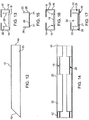
- the magazine 12 includes an elongate staple guide assembly 14. Detail of the staple guide assembly 14 can be seen in figures 14 to 17 .
- the staple guide assembly 14 includes an outer guide member 20 that defines a pair of sidewalls 16 and a floor 18 interposed between the sidewalls 16.
- An inner guide member 22 is positioned on the floor 18 between the sidewalls 16.
- the inner guide member 22 also has a floor 24 that is positioned on the floor 18 with sidewalls 26 extending from the floor 24 so that the guide assembly 14 defines a pair of outer channels 28 and a central channel 30 interposed between the outer channels 28.
- the floor 18 defines a pair of longitudinally extending slots 19.
- the floor 24 defines a pair of corresponding, longitudinal ribs or ridges 21.
- the slots 19 and the ridges 21 have complementary cross sectional shapes so that the ridges 21 that can slide into the slots 19.
- the shapes of the slots 19 and the ridges 21 are such that the inner and outer guide members 20, 21 are inhibited from lateral displacement with respect to each other.
- the magazine 12 can have a length that is suited for a particular application. For example, joists and rafters are often spaced at about 400 mm. The magazine 12 can thus have a length of about 390 mm to fit between the joists and the rafters.
- the inner and outer guide members 22, 20 can take different forms and can be fabricated in different ways.
- the inner and outer guide members 22, 20 can be in the form of an extrusion to define a unitary structure in the form of a staple guide 15.
- the relevant mould can be configured so that the extrusion defines a common floor and two pairs of sidewalls 16, 26.
- An example of such an extrusion is shown in figures 12 and 13 .
- the same reference numerals are used as in figures 14 to 17 .
- the floor 18 is taken between the inner guide members 22.
- the guide assembly 14 or staple guide 15 includes a pair of roof members 32.
- the roof members 32 are arranged on the sidewalls 16 and extend inwardly from the sidewalls 16 to cover the outer channels 28.
- the roof members 32 define cut-outs or recesses 29 at or near a feed end 40 of the assembly 14. Staples 34 can be fed into the assembly 14 via the recesses 29.
- Discharge ends 42 of the inner and outer guide members 22, 20 are located in a common plane that is angled towards the feed end 40 from the floor 18.
- the angle between the common plane and the floor 18 is about 45°.
- the angle can vary, for example, between about 40° and 90°, depending on the required application. In this example, the angle is about 45°.
- truss and frame fabricators would likely require a 90° angle.
- Many nail guns have magazine angles that are measured from a horizontal plane and not from a vertical plane. It is to be understood that the above measurements are taken between said common plane and the floor 18 as opposed to an external reference. Thus, if the angle mentioned above is 20° (quite common in nail guns), it would be 20° if the floor 18 is in a horizontal plane. However, it can also be understood to be 70° with respect to a vertical plane.
- the guide assembly 14 includes a tension block 44 that is mounted in the channels 28, 30 to slide between the feed and discharge ends 40, 42, respectively.
- the tension block 44 is shown in some detail in figure 7 .
- the tension block 44 has a pair of outer bearers 46 that define bearing faces 48 configured to bear against respective legs 36 of the last staple in a row of the staples 34.
- the outer bearers 46 are received in respective outer channels 28. In that condition, the bearing faces 48 are oriented in a plane generally parallel to said common plane of the discharge ends 42 of the inner and outer guide members 22, 20.
- a cross member 50 interconnects the bearers 46 to span the central channel 30.
- the cross member 50 defines a central bearing face 52 that is slightly recessed with respect to the bearing faces 48.
- the central bearing face 52 is oriented in a plane generally parallel to said common plane of the discharge ends of the inner and outer guide members 22, 20.
- a pair of internal guides 54 depends from the cross member 50 and is received in the central channel 30.
- the tension block 44 is spring mounted in the guide assembly 14 to be biased towards the discharge end 42.
- the tension block 44 includes a reel or a roll of a length of spring steel 56.
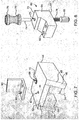
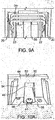
- One end 58 is fastened to the floor 24 at the discharge end 42 with a fastener such as a screw 41 ( figures 9 and 10 ).
- a fastener such as a screw 41 ( figures 9 and 10 ).
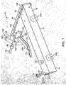
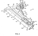
- the tension block 44 is withdrawn to its pre-release condition, for example, as shown in figures 1 and 2 , the length of steel is largely unrolled.
- the length of spring steel 56 has an arcuate transverse profile that serves to bias the length into a rolled up condition. It follows that retention of the tension block 44 in the pre-release condition is against the bias of the length of spring steel 56.
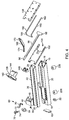
- the tension block 44 is also shown in a pre-release condition in figures 5 and 6 .
- the length of spring steel 56 is rolled and unrolled on and off a roller or reel 45 ( figure 10A ), rotatably mounted on the tension block 44.
- tension block 44 and the length of spring steel 56 together define part of a feed mechanism for feeding for staples 34 from the feed end to the discharge end of the guide assembly 14.
- a catch assembly 60 is mounted on the guide assembly 14 to engage the tension block 44 in a releasable manner when the tension block 44 is in a pre-release condition.
- the catch assembly 60 includes a catch block 64.
- the catch block 64 extends along and over the central channel 30.
- a mounting block 62 is mounted between the sidewalls 16 at the feed end 40 of the assembly 14.
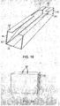
- the mounting block 62 defines a pair of threaded holes 63 ( figure 19 ).
- the catch block 64 defines a pair of corresponding passages 65 so that the catch block 64 can be fastened to the mounting block 62 with suitable fasteners 67 ( figure 6 ).
- a catch 66 is mounted on the catch block 64 and is displaceable relative thereto between an inoperative and an operative position.
- the tension block 44 defines a catch recess 68 in which the catch 66 can be received when the tension block 44 is in the pre-release condition or position.
- the catch assembly 60 includes a finger pull handle 70 that is fastened to the catch 66 so that a user can move the catch 66 from the operative to the inoperative position.
- the catch 66 can be biased into the operative position.
- the catch 66 can be spring mounted on the catch block 64.
- the tension block 44 can be shaped to define a ramp 72 that extends from a feed end to the recess 68.
- the catch 66 can be generally cylindrical with a rounded end. The catch 66 and the ramp 72 are positioned so that when the tension block 44 is drawn towards the feed end, or cocked, the catch 66 engages the ramp 72 and is urged upwardly against its bias until it is urged into the recess 68.
- the handle 70 comprises a shank 74.
- a gripping formation or arrangement 76 is positioned on the shank 74.
- the catch block 64 defines a passage 75 extending between a handle side 73 and a catch side 77 of the block 64 ( figure 8 ).
- the shank 74 extends into the passage 75 and is fastened to the catch 66.
- a spring 78 is received in the catch block 64 to engage the catch 66 and the catch block 64 to provide the necessary bias.
- a handle mount 43 can serve to mount a tension block handle to the cross member 50 to extend beyond respective sidewalls 16.
- the tension block 44 can define a pair of threaded holes 47 that corresponds with a pair of openings 49 in the mount 43.
- the handle can be fastened to the tension block 44 with suitable fasteners. A user can use the handle to draw the tension block 44 back into its pre-release condition.
- a tension block handle 80 is fastened to the tension block 44 with a pair of threaded fasteners 81, as shown in figures 5 and 6 .
- a user can use the handle 82 to draw the tension block 44 back into its pre-release condition with one hand.
- a handle formation 82 extends from one of the sidewalls 16 and is oppositely oriented relative to the handle 80 so that a user can hold the accessory 10 in a stable condition while withdrawing the tension block 44.
- the accessory 10 includes a drive member guide assembly 84.
- the drive member guide assembly 84 is configured to guide a drive member 86 when the drive member is driven into engagement with a staple 34 fed from the magazine 12.
- the drive member 86 can have a number of different shapes and configurations.
- the drive member 86 is formed from a flat sheet of steel so that the drive member 86 has a pair of opposed flat surfaces.
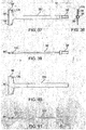
- the drive member 86 has a head 88 with a crown-engaging surface 90 and a shank 92 extending from the head 88 so that the drive member 86 has a generally T-shaped appearance ( figures 35 to 45 ).
- a locator 94 is positioned at each end of the surface 90 to locate the crown 38 of the staple 34 with respect to the crown engaging surface 90.
- the surface 90 has a curved or arcuate transverse profile that corresponds generally with a transverse profile of the crown 38 of the staples 34. This facilitates pickup of the staple 34 as the drive member 86 is driven towards the workpiece.
- FIG. 37 An exemplary embodiment of a drive member 96 is shown in figures 37 to 38 .
- the drive member 96 is of a one-piece construction with a connector 98 fixed to a distal end of the shank 92.
- the connector 98 is generally cylindrical and threaded so that it can be screwed into a piston of the fastening gun.
- FIG. 40 A further exemplary embodiment of a drive member 100 is shown in figures 40 and 41 .
- the shank 92 incorporates a connector as part of the flat sheet of steel referred to above.
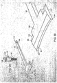
- the guide assembly 84 has a guide plate 102 that is fastened to the outer guide member 20.
- the guide plate 102 defines a recess 104 at a discharge end that is profiled to correspond with an external profile of the outer guide member 20. Detail of the guide plate 102 can be seen in figures 29 and 30 .
- a distal end of the plate 102 is bevelled at 106 to be coplanar with the floor 18 of the outer guide member 20.
- the guide plate 102 can be welded to the guide member 20.
- the angle between the guide plate 102 and the floor 18 is about 45°. However, the angle can vary, for example, between about 40° and 90°. It follows that the drive member guide assembly 84 and the magazine 12 are oriented at these angles with respect to each other.
- a cover plate 108 is fastened to the guide plate 102.
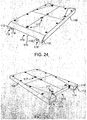
- An inner surface 110 of the cover plate 108 defines a pair of external walls 112 and a pair of internal walls 114.
- the walls 112, 114, together with the guide plate 102 define an internal passage 116 in which the head 88 of the drive member can be displaced towards and away from a workpiece.
- the passage 116 also defines a guide path for the staples 34, once they are fed from the staple guide assembly 14 into a striking position. Details of the cover plate 108 can be seen in figures 24 to 28 .
- the walls 112, 114 together with the guide plate 102 define a pair of external passages 118.
- the purpose of these passages 106 is described below.
- the cover plate 108 is dimensioned to cover both the guide plate 102 and the discharge end 42 of the assembly 14.
- the walls 112, 114 are dimensioned so that a space or gap between the guide plate 102 and the cover plate 108 corresponds generally with a thickness of a staple 34.
- a foremost staple 34 can be received in the space or gap prior to being driven into a workpiece by the drive member as the drive member is driven towards the workpiece.
- the cover plate 108 is fastened to the guide plate 102 with releasable fasteners. This enables the cover plate 108 to be removed from the guide plate 102 for servicing and clearing of the passage 116. Also, the fact that the cover plate 108 can be removed allows spare parts to be supplied using larger numbers of smaller components to extend the life of the accessory 10.
- the cover plate 108 includes or defines viewing apertures 117 so that an operator can check for any problems within the internal passage 116.
- the drive member can take a number of different configurations.
- the drive member does have common features, shown in figure 36 . These include an upper edge of the head 88 which is partially bevelled at 120.
- the bevel extends from a surface 122 that is directed towards the staple guide assembly 14, in use, to an opposed surface 124.
- the bevelled areas 120 are in general alignment with the legs 36 of the staples 34. This inhibits obstruction or interference between the head 88 and the staples 34, once a staple has been driven into the workpiece and the drive member is retracted.
- the accessory 10 can include a connector 126 ( figure 34 ) for connecting the shank 92 of the drive member to a piston (not shown) of the gun.
- the connector 126 includes a cylindrical head 128 that defines a diametric slot 130.
- a passage 132 extends through the head 128, transversely with respect to the slot 130.
- a free end of the shank 92 can be received in the slot 130.
- An opening 134 is defined in the shank 92 and is positioned so that when the free end of the shank 92 is received in the slot 130, the opening 134 is aligned with the passage 132.
- the shank 92 can be pinned to the head 128 with a suitable pivot pin or the like received through the passage 132 and the opening 134.
- a threaded shank 136 extends from the head 128.
- the shank 136 can be threaded into the end of a piston of the gun.
- the threaded shank 136 can be of a suitable length so that a stroke length of the drive member can be adjusted depending on the extent to which the shank 136 is threaded into the piston of the gun
- the accessory 10 includes an adapter 138 ( figure 31 ) so that the drive member guide assembly 84 can be connected to the gun.
- the adapter 138 includes an adapter plate 140 that can be fastened to a mounting plate of the gun with fasteners received through openings 142.
- a locating formation 144 extends from the adapter plate 140.
- the locating formation 144 and the adapter plate 140 define a passage 146.
- the shank 92 extends through the passage 146 to engage the piston, as described above.
- a proximal end 139 of the guide plate 102 defines a recess 150 to receive the locating formation 144 ( figure 29 ).
- the locating formation 144 defines a shoulder 152 that can abut the assembly 84 in the recess 150.
- the locating formation 144 also defines a pair of opposed ledges 154.
- the ledges 154 are positioned on opposite sides of the passage 146 and are configured and oriented to bear against proximal sides of the head 88.
- the adapter 138 can serve to inhibit excessive retraction of the drive member.
- An extent of retraction can also be governed by a rubber or elastomeric bush or stopper arrangement 156 ( figure 49 , for example) above a piston 194 to which the drive member is attached.
- the ledges 154 are positioned and the bush 156 is configured so that there is clearance between the head 88 of the drive member 86 and the ledges 154. Also, the bush 156 can absorb any impact and thus inhibit damage to the adaptor 138 or drive member.
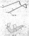
- the accessory 10 includes a safety pin 160 ( figure 32 ) that includes two opposed legs 162 that are received in respective external passages 118 ( figures 24, 25 ).
- a bridge member or bridge 166 interconnects proximal ends of the legs 162.
- the bridge 166 is shaped to accommodate a body of the fastening gun. More particularly, the bridge 166 is bent generally orthogonally with respect to the legs 162.
- the proximal end 139 of the guide plate 102 defines a pair of opposed recesses 95 to accommodate the bridge 166.
- a safety connector 168 shown in figure 33 , is pivotally connected to the bridge 166 and to a safety mechanism or a trigger mechanism of the fastening gun.
- the safety connector 168 can have any number of different configurations, depending on the nature of the fastening gun with which it is to be used.
- the safety connector 168 has a connecting formation 170 that defines a pair of openings 172, for example, through which the bridge 166 is received.
- a lug 174 is connected to the formation 170 and is configured to engage the safety mechanism of the fastening gun. It is to be appreciated that the safety connector 168 will have a configuration that is dependent on the safety mechanism of the fastening gun. Thus, the inventor(s) envisages that the safety connector 168 can have a number of different shapes, if necessary.
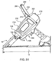
- the adapter 138 is configured so that the magazine extends past the fastening gun. See, for example, figure 51 .
- the legs 162 are dimensioned so that distal ends 176 ( figure 11 ) of the legs 162 protrude from the respective passages 164 to engage a workpiece when the guide assembly 84 is pressed against the workpiece. This causes the safety pin 160 to be displaced towards the gun and to release the safety mechanism of the gun, via the safety connector 168.
- a biasing mechanism is provided to bias the safety pin 160 into a position in which the safety mechanism of the fastening gun is operable.
- the safety pin 160 is biased into the condition or position shown in figure 11 .
- the biasing mechanism includes a compression spring 178 that is interposed between the bridge 166 and the adaptor 138 ( figure 51 ).
- the drive member When the gun is triggered, the drive member is driven towards the workpiece, guided in the internal passage 116.
- the crown engaging surface 90 engages the crown 38 of a foremost staple 34 and drives the legs 36 into the workpiece.
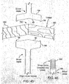
- the accessory 10 is useful for fastening truss members 180 together, as shown in figure 45 . It is known that ends of truss members are mitred so that the truss can define a peak or apex 182. Thus, when using the staples 34 to connect the truss members 180, it is necessary to drive each leg 36 into a respective truss member 180.
- the accessory 10 can be provided with two forms of drive member. One can have a driver blade 184 for driving staples 34 into outer surfaces of the truss members 180 and a driver blade 186 for driving staples 34 into inner surfaces of the truss members 180.
- the crown engaging surface 90 of the driver blade 184 defines an included angle that corresponds generally with an excluded angle defined by the truss members 180 when joined together.
- driver blade 186 has a crown engaging surface 90 that defines an excluded angle that corresponds generally with an included angle defined by the truss members 180 when joined together.
- the driver blades 184, 186 have a shank 188 that defines a threaded portion 190 at a free end to allow the shank to be threaded directly into a piston of the gun.
- the accessory 10 can be supplied with a number of different forms of drive member.
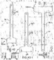
- figures 42 to 44 show three different forms of drive member 86. These are provided for differently sized staples.
- the drive member 86.1 has a head 88.1 that is suited for a staple having a crown with a length of about 50 mm.
- the drive member 86.2 has a head 88.2 suited for a staple having a crown with a length of about 70 mm.
- the drive member 86.3 has a head 88.3 suited for a staple having a crown with a length of about 100 mm.
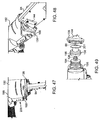
- FIGs 47 to 49 illustrate further the manner in which the accessory 10 is mounted on a fastening gun, in this embodiment, referenced with 192.
- the fastening gun 192 has a pneumatic piston 194 that is mounted in a barrel 196.
- the connector 126 is screwed into the piston 194.
- the rubber bush or stopper arrangement 156 is interposed between the piston 194 and the adaptor 138.
- the bush 156 serves to facilitate retraction of the drive member and also protects the adaptor 138 and drive member by absorbing impact.
- the shank 86 of the drive member 180 extends through the adapter 138 and the bush 156, as can be seen.
- the stopper arrangement 156 includes a bellows-like structure 198 and a piston-like structure 201 that extends from the structure 198.
- the stopper arrangement 156 is oriented so that the structure 201 is received in the adapter 138 while the structure 198 bears against the piston 194.
- the structure 201 and the structure 198 are driven towards each other.
- the safety connector 168 is received in a housing 199 of the gun 192 to engage the safety mechanism indicated at 200. Engagement is in such a manner that displacement of the safety connector 168 as the safety pin 160 is pressed against the workpiece disengages the safety mechanism allowing operation of the gun 192.
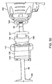
- FIG 50 there is shown another example of a manner in which the accessory 10 is mounted on a fastening gun, in this example, referenced with 202.
- like reference numerals refer to like parts, unless otherwise specified.
- the drive member is in the form of a unitary one piece structure.
- An example of the drive member is shown in figures 37 to 39 .
- the drive member is screwed directly into the piston 194.
- an orientation of the stopper arrangement 156 is reversed when compared with the assembly shown in figures 37 to 39 .
- FIG 51 there is shown the accessory 10 connected to the gun 202.
- the safety connector 168 is connected to a safety mechanism 200 of the gun 202.
- the safety mechanism 200 is disengaged allowing the gun 202 to be fired.
- FIG 51 there is shown a handle 204 connected to the gun 202.
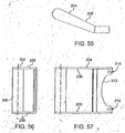
- the handle 204 includes a handgrip 206 and a pair of legs 208, each leg 208 extending from a respective end of the handgrip 206.
- Detail of the handle 204 can be seen in figures 55 to 57 .
- the legs 208 are configured to be fastened to a housing or casing assembly 210 of the gun 202.
- a bridge member 212 interconnects the legs 208.
- the bridge member 212 is recessed to accommodate a portion of the casing assembly so that the bridge member 212 can nest with the casing assembly 210.
- the bridge member 212 defines a pair of openings 214 that corresponds with openings in a rear casing member 216 that is fastened to a front casing member 218 with fasteners, in a conventional manner.
- the bridge member 212 can be fastened to the rear casing member 216 with the fasteners used to fasten the rear and front casing members 216, 218 together.
- the guide members 22, 24 can be of a material that is relatively light in weight compared to steel.
- the guide members 22, 24 can be of aluminium or of an aluminium alloy.
- the drive member can be of a high strength material, such as a suitable steel.
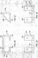
- a guide protection member 248 is mounted on the floor 24 of the inner guide member 22. Detail of the manner in which the guide protection member 248 is assembled, as shown in figures 9 and 10 . Detail of the guide protection member 248, itself, is shown in figures 20 to 23 .
- the guide protection member 248 has a pair of legs 250 that depend from respective ends of a cross member 252.
- a foot 254 extends inwardly from respective ends of the legs 250.
- the cross member 252, the feet 254 and the legs 250 define a wear surface 256.
- the feet 254 are fastened to the floor 24 with suitable fasteners such as screws 258.
- the legs 250 and the feet 254 are oriented with respect to each other so that the wear surface 256 and the discharge ends 42 of the inner and outer guide members 22, 20 are generally coplanar.
- the guide protection member 248 is of steel or a metal with similar wear properties. Thus, the guide protection member 248 can protect the guide members 22, 24 from wear.
- nail strike This can occur when nails or staples are driven into respective opposite sides of a workpiece and one of the nails or staples strikes another nail or staple. This can have a significant effect on joint strength and often causes splitting of timber.
- the accessory 10 can include a pair of guide pin assemblies 220 ( figures 52 to 54 ).
- the floor 18 defines a pair of spaced lateral slots 222.
- Each guide pin assembly 220 includes a guide pin 224 and a head 226 arranged at one end of the guide pin 224.
- a flange 228 is interposed between the head 226 and the guide pin 224.
- the head 226 is dimensioned to fit through an associated slot 222 with a flange 228 bearing against an underneath surface 210 of the floor 18.
- Each guide pin assembly 220 includes a cylindrical retainer 230 that can be received in the central channel 30.
- the cylindrical retainers 230 each define a socket 232 in which a respective head 226 can be received.
- Each head 226 has a threaded socket to receive a fastener 234 that extends through the associated retainer 230.
- the guide pins 224 can be offset with respect to each other.
- the spacing between the guide pins 224 is selected so that when a fastening operation is carried out, a workpiece can be received between the guide pins 224 when the gun is operated from one side of the workpiece.
- the orientation of the gun is such that nail strike is avoided.
- Figures 1 to 4 show an embodiment that includes guide pins 236 that are of sufficient diameter that lateral adjustment is unnecessary. It follows that the lateral slots together with the fastening arrangement described above are not required. In this case, the guide pins 236 are generally longitudinally aligned and spaced so that they can be used in the manner described above.
- the guide pins 236 can be configured so that when the accessory 10 is used to connect truss members, and the gun is moved from one side of a truss to the other side, there is a separation of about 6 mm at the point of entry of the staples on each side of the truss and the top plate to which the truss is being fixed.
- use of the guide pin assemblies 220 or the guide pins 236 can eliminate "nail strike” when inserting nails or staples from opposite sides of a workpiece. This can be achieved without having carefully to align the gun to ensure that the trajectory or path of the nail or staple does not intersect with a previously set nail or staple. It will be appreciated that this can result in a significant saving of time and can avoid the problems associated with nail strike as mentioned above.
- the safety bar 238 is mounted on the guide assembly 84 so that the two opposed legs 162 extend in a plane that is spaced forwardly of a plane in which the drive member operates. This is in contrast to the previous example in which the safety pin 160 operates in a plane that is generally common with the plane of the drive member.
- the safety bar 238 is mounted so that the legs 162 are positioned in front of the guide assembly 84.
- the guide assembly 84 can include a rebate 239 to accommodate the legs 162 ( figure 59 ).
- a faceplate 246 can be fastened to the guide assembly 84 to cover the legs 162.
- the bridge 166 is shaped to define an end portion 240 that engages a trigger safety bar 242 of the gun, indicated at 244.
- the end portion 240 is bent over an upper end 245 of the guide assembly 84 and accommodates the adapter 138.
Landscapes
- Engineering & Computer Science (AREA)
- Mechanical Engineering (AREA)
- Portable Nailing Machines And Staplers (AREA)
Claims (13)
- Zubehör (10) für eine Befestigungspistole, umfassend
eine Magazineinheit (12) mit einem Zuführende (40) und einem Abgabeende (42), das konfiguriert ist, eine Reihe von Klammern (34) in einer Vorabgabeausrichtung zu tragen, und das einen Zuführungsmechanismus aufweist, um die Klammern vom Zuführende (40) in Richtung auf das Abgabeende (42) zuzuführen;
ein Klammertreibelement (86), wobei das Klammertreibelement ein Paar von gegenüberstehenden generell flachen Flächen definiert und einen Kopf (88) mit einer Scheiteleingriffsfläche (90) und einen Schaft (92) aufweist, der sich vom Kopf (88) erstreckt, sodass das Klammertreibelement (86) ein generell T-förmiges Aussehen aufweist; und
eine Treibelementführungseinheit (84), umfassend eine Führungsplatte (102), die an einem länglichen äußeren Führungselement (20) der Magazineinheit befestigt ist, und eine Abdeckplatte (108), die an der Führungsplatte (102) befestigt ist, wobei eine Innenfläche (110) der Abdeckplatte und der Führungsplatte einen inneren Durchgang (116) definieren, in dem der Kopf (88) des Treibelements (86) in Richtung auf ein Werkstück und davon weg verschoben werden kann, und wobei die Abdeckplatte (108) und die Führungsplatte (102) derart konfiguriert sind, dass der innere Durchgang auch eine Führungsbahn für die Klammern definiert, sobald sie von einer Klammerführungseinheit (14) zugeführt werden,
wobei die Treibelementführungseinheit (84) an der Magazineinheit (12) befestigt ist und das Klammertreibelement (86) in der Treibelementführungseinheit (84) befestigt ist, um entlang eines in Bezug auf die Magazineinheit (12) vorbestimmten Wegs getrieben und zurückgezogen zu werden, sodass beim Treiben das Klammertreibelement (86) in eine Klammer (34) eingreifen kann, um Schenkel (36) der Klammer (34) in entsprechende Komponenten zu treiben, wobei die Treibelementführungseinheit (84) konfiguriert ist, an der Befestigungspistole befestigt zu werden, wobei das Klammertreibelement (86) mit einem Kolben oder dergleichen der Befestigungspistole verbunden ist. - Zubehör nach Anspruch 1, wobei die Treibelementführungseinheit (84) konfiguriert ist, mit dem Klammertreibelement (86), das einen Kopf (88) aufweist, der konfiguriert ist, an einem Scheitel (38) der Klammer (34) anzuliegen, und dem Schaft (92), der mit einem Kolben oder dergleichen der Befestigungspistole verbunden sein kann, zusammenzuwirken.
- Zubehör nach Anspruch 2, wobei das längliche äußere Führungselement (20) der Magazineinheit (12) ein Paar von Seitenwänden (16), einen Boden (18), der zwischen den Seitenwänden eingeschoben ist, und ein inneres Führungselement (22), das auf dem Boden (18) zwischen den Seitenwänden (16) positioniert ist, definiert, sodass die Führungselemente (20, 22) ein Paar von äußeren Kanälen (28) und einen zentralen Kanal (30), der zwischen den äußeren Kanälen (28) eingeschoben ist, definieren.
- Zubehör nach Anspruch 3, wobei ein Paar von Dachelementen (32) an entsprechenden Seitenwänden (16) des länglichen äußeren Führungselements (20) angeordnet ist und sich von den Seitenwänden (16) nach innen erstreckt, um die äußeren Kanäle (28) mindestens teilweise abzudecken, wobei die Dachelemente (32) eine Aussparung (29) an oder nahe einem Zuführende (40) der Treibelementführungseinheit (84) definieren, sodass Klammern (34) über die Aussparung (29) in die Treibelementführungseinheit (84) zugeführt werden können.
- Zubehör nach Anspruch 4, wobei sich Abgabeenden (42) der inneren und äußeren Führungselemente (22, 20) in einer gemeinsamen Ebene befinden, die in Richtung auf das Zuführende (40) vom Boden (18) abgewinkelt ist.
- Zubehör nach Anspruch 3, wobei der Zuführungsmechanismus einen Spannungsblock (44) umfasst, der in den äußeren und den zentralen Kanälen (28, 30) angebracht ist, und der Spannungsblock (44) äußere Träger (46) definiert, die in entsprechenden äußeren Kanälen (28) aufgenommen sind und Auflageflächen (48) aufweisen, die konfiguriert sind, an entsprechenden Schenkeln (36) der letzten Klammer (34) in einer Reihe der Klammern anzuliegen.
- Zubehör nach Anspruch 6, wobei der Spannungsblock (44) ein Querelement (50) umfasst, welches die Träger (46) miteinander verbindet, sodass sie den zentralen Kanal (30) überspannen, und das Querelement (50) eine zentrale Auflagefläche (52) definiert, die in Bezug auf die Auflageflächen (48) zurückgesetzt und in einer Ebene ausgerichtet ist, die zur gemeinsamen Ebene der Abgabeenden (42) der inneren und äußeren Führungselemente (22, 20) generell parallel ist.
- Zubehör nach Anspruch 6, wobei der Spannungsblock (44) in den äußeren und den Zentralkanälen (28, 30) federgelagert ist, sodass er in Richtung auf die Abgabeenden (42) der inneren und äußeren Führungselemente (22, 20) vorgespannt ist, und eine Verschlusseinheit (60) an der Klammerführungseinheit (14) angebracht ist, sodass sie in einer lösbaren Weise in den Spannungsblock (44) eingreift, wenn sich der Spannungsblock (44) in einem Vorfreigabezustand befindet.
- Zubehör nach Anspruch 1, wobei das Klammertreibelement (86) ein Lokalisierungselement (94) aufweist, das an jedem Ende der Scheiteleingriffsfläche (90) positioniert ist, um den Scheitel der Klammer (34) in Bezug auf die Scheiteleingriffsfläche (90) zu lokalisieren, wobei das Klammertreibelement (86) ein Verbindungsstück (98) umfasst, das an einem distalen Ende des Schafts (92) fixiert ist, sodass das Klammertreibelement (86) mit einem Kolben der Befestigungspistole verbunden werden kann.
- Zubehör nach Anspruch 1, das eine Sicherungsstifteinheit umfasst, die in Bezug auf die Treibelementführungseinheit (84) linear verschiebbar angeordnet ist, und die einen Sicherungsstift (160) umfasst, der derart konfiguriert ist, dass er zwischen einer ausgefahrenen Stellung, in der sich ein Abschnitt des Sicherungsstifts (160) über ein distales Ende der Treibelementführungseinheit (84) hinaus erstreckt, und einer eingefahrenen Stellung verschiebbar ist.
- Zubehör nach Anspruch 10, wobei die Sicherungsstifteinheit ein Sicherungsverbindungsstück (168) umfasst, das zu einer Verbindung sowohl mit dem Sicherungsstift (160) als auch einem Sicherheitsmechanismus (200) der Befestigungspistole fähig ist, wobei der Sicherungsstift (160) und das Sicherungsverbindungsstück (168) derart konfiguriert sind, dass der Sicherheitsmechanismus (200) der Befestigungspistole gelöst wird und die Pistole feuern kann, wenn sich der Sicherungsstift (160) von der ausgefahrenen Stellung in die eingefahrene Stellung bewegt.
- Zubehör nach Anspruch 1, wobei die Magazineinheit (12) eine Basis, die zum Anliegen an einem Werkstück konfiguriert ist, während die Befestigungspistole betrieben wird, und eine Führungsanordnung umfasst, die auf der Basis angeordnet und konfiguriert ist, die Basis gegen das Werkstück zu führen, sodass die Bahn eines Befestigungselements, das aus dem Magazin ausgestoßen und von einer Seite des Werkstücks in das Werkstück getrieben wird, zu der Bahn eines Befestigungselements versetzt ist, das von einer gegenüberliegenden Seite in das Werkstück getrieben wird, sodass eine gegenseitige Beeinflussung der Befestigungselemente verhindert wird, wobei die Führungsanordnung die Form eines Paars von Stiften (224) aufweist, die sich von der Basis erstrecken, und die Stifte (224) derart positioniert sind, dass das Werkstück zwischen den Stiften aufgenommen werden kann, und die Stifte einen Durchmesser aufweisen, der ausreichend ist, um eine nichtsymmetrische Ausrichtung des Magazins in Bezug auf das Werkstück auf gegenüberliegenden Seiten des Werkstücks bereitzustellen.
- Befestigungspistole, die das Zubehör nach Anspruch 1 umfasst.
Applications Claiming Priority (3)
| Application Number | Priority Date | Filing Date | Title |
|---|---|---|---|
| AU2012902547A AU2012902547A0 (en) | 2012-06-18 | Stapler Parts | |
| AU2012905288A AU2012905288A0 (en) | 2012-12-05 | An Accessory for a Fastening Gun | |
| PCT/AU2013/000641 WO2013188905A1 (en) | 2012-06-18 | 2013-06-18 | An accessory for a fastening gun |
Publications (3)
| Publication Number | Publication Date |
|---|---|
| EP2861380A1 EP2861380A1 (de) | 2015-04-22 |
| EP2861380A4 EP2861380A4 (de) | 2016-04-06 |
| EP2861380B1 true EP2861380B1 (de) | 2017-08-09 |
Family
ID=49767929
Family Applications (1)
| Application Number | Title | Priority Date | Filing Date |
|---|---|---|---|
| EP13807315.0A Not-in-force EP2861380B1 (de) | 2012-06-18 | 2013-06-18 | Zubehör für eine befestigungspistole |
Country Status (5)
| Country | Link |
|---|---|
| US (1) | US10391619B2 (de) |
| EP (1) | EP2861380B1 (de) |
| AU (1) | AU2013277922B2 (de) |
| CA (1) | CA2915513C (de) |
| WO (1) | WO2013188905A1 (de) |
Cited By (1)
| Publication number | Priority date | Publication date | Assignee | Title |
|---|---|---|---|---|
| US11633839B2 (en) | 2016-03-22 | 2023-04-25 | Stanley Black & Decker, Inc. | Safety device for tackers |
Family Cites Families (71)
| Publication number | Priority date | Publication date | Assignee | Title |
|---|---|---|---|---|
| US2733440A (en) * | 1956-02-07 | Stapling implement | ||
| US1987038A (en) * | 1931-12-01 | 1935-01-08 | Hotchkiss Co E H | Staple driving device |
| US1945377A (en) * | 1933-10-25 | 1934-01-30 | Charles B Goodstein | Stapling machine |
| US2087779A (en) * | 1934-06-21 | 1937-07-20 | William G Pankonin | Stapling device |
| US2351045A (en) | 1942-06-25 | 1944-06-13 | Harold S Heller | Staple |
| US2380655A (en) | 1942-11-30 | 1945-07-31 | Bocjl Corp | Staple and method of stapling |
| US2437039A (en) * | 1945-03-16 | 1948-03-02 | Hotchkiss Realty Corp | Staple driving implement |
| US2489050A (en) * | 1945-08-04 | 1949-11-22 | Speed Products Company Inc | Stapling machine |
| US2691778A (en) * | 1950-09-08 | 1954-10-19 | Lou Obstfeld | Staple driving machine |
| US2775764A (en) * | 1954-03-10 | 1957-01-01 | Bostitch Inc | Stapling machine |
| US2873447A (en) * | 1956-04-05 | 1959-02-17 | Remington Arms Co Inc | Cartridge-operated staple-driving tool |
| US2857596A (en) * | 1957-04-01 | 1958-10-28 | Bostitch Inc | Fastener-applying machine |
| US3266138A (en) | 1964-09-11 | 1966-08-16 | Rheem Mfg Co | Method of applying clips |
| DE1908012A1 (de) * | 1969-02-18 | 1970-08-27 | Behrens Friedrich Joh | Geraet zum Eintreiben von verschiedenartigen Befestigungsmitteln |
| US3610505A (en) * | 1969-05-12 | 1971-10-05 | Textron Inc | Spring-operated fastener driving device |
| US3856139A (en) * | 1969-10-27 | 1974-12-24 | Co Woodloc Inc | Carrier means for automatically driven fasteners |
| US3601300A (en) * | 1970-01-23 | 1971-08-24 | Edgar P Anstett | Pneumatically operated nailing machine |
| US3862712A (en) * | 1973-08-27 | 1975-01-28 | Parker Mfg Co | Stapler |
| US3934778A (en) * | 1975-02-13 | 1976-01-27 | Textron, Inc. | Staple driving device with improved staple jam clearing mechanism |
| SE406287B (sv) * | 1976-05-17 | 1979-02-05 | Isabergs Verkstads Ab | Anordning vid ett verktyg for att med ett slag indriva ett festorgan |
| US4327858A (en) | 1979-12-26 | 1982-05-04 | Power-Line Sales, Inc. | Non jamming head and magazine for fastener driving tool |
| US4380312A (en) | 1980-07-17 | 1983-04-19 | Minnesota Mining And Manufacturing Company | Stapling tool |
| DE3070540D1 (en) | 1980-08-07 | 1985-05-23 | Swingline Inc | A fastener driving tool for corners |
| US4485952A (en) | 1982-06-03 | 1984-12-04 | Power-Line Fastener Systems, Inc. | Shiftable magazine clip feed for fastener driving tools |
| US4552296A (en) * | 1983-10-19 | 1985-11-12 | Wang Sheng | Stapling gun |
| US4574992A (en) | 1984-08-24 | 1986-03-11 | Duo-Fast Corporation | Clinching type stapler |
| JPS6239981U (de) * | 1985-08-23 | 1987-03-10 | ||
| US5009356A (en) * | 1990-01-08 | 1991-04-23 | Ted Chang | Removable magazine for staple guns |
| US5360305A (en) | 1993-03-19 | 1994-11-01 | Duo-Fast Corporation | Clinch staples and method of manufacturing and applying clinch staples |
| SE501017C2 (sv) | 1993-03-24 | 1994-10-17 | Arfo Produkter Ab | Tillsatsaggregat för en portabel indrivningsanordning |
| US5524807A (en) * | 1994-12-02 | 1996-06-11 | Bullard; Robert | Fastener tool |
| US5628445A (en) * | 1995-06-05 | 1997-05-13 | Senco Products, Inc. | Shingle gauge for use with nail driving tool |
| US5695108A (en) * | 1996-03-05 | 1997-12-09 | De Poan Pneumatic Corporation | Magazine system of a stapler |
| US5846019A (en) | 1996-08-06 | 1998-12-08 | Kuhns; Philip A. | Fasteners |
| US5813588A (en) * | 1996-10-09 | 1998-09-29 | Lin; George | Magazine assembly for fastener driving tools |
| EP1033209B1 (de) * | 1999-03-04 | 2007-05-30 | Max Co., Ltd. | Mechanismus des Magazins für eine Nagelmaschine |
| US6659700B1 (en) | 1999-11-29 | 2003-12-09 | Evening Star International, Inc. | Metal piercing fastener |
| JP3780822B2 (ja) * | 2000-05-23 | 2006-05-31 | 日立工機株式会社 | 釘打機 |
| US6454151B1 (en) * | 2000-07-17 | 2002-09-24 | Lin Wang-Kuan | Power stapler |
| US20020117531A1 (en) | 2001-02-07 | 2002-08-29 | Schell Craig A. | Fastener tool |
| US7106739B2 (en) * | 2001-06-27 | 2006-09-12 | Intel Corporation | Method enabling network address translation of incoming session initiation protocol connections based on dynamic host configuration protocol address assignments |
| US6843402B2 (en) * | 2001-08-03 | 2005-01-18 | Peace Industries, Ltd. | Adjustable tool mount |
| US7011242B2 (en) * | 2001-12-07 | 2006-03-14 | Acme Staple Company, Inc. | Coated staple and fastening tool for the same |
| US6481612B1 (en) * | 2002-04-02 | 2002-11-19 | Peter G. Mangone, Jr. | Fastening device delivery tool with perpendicular ram driven by a repeatable arcuate force member |
| US6957756B2 (en) * | 2002-04-10 | 2005-10-25 | Illinois Tool Works Inc. | Tool with nosepiece for bending fastener upon installation and fastener therefor |
| US6808101B2 (en) * | 2002-05-24 | 2004-10-26 | Illinois Tool Works Inc. | Framing tool with automatic fastener-size adjustment |
| US6779697B2 (en) * | 2002-08-26 | 2004-08-24 | Wang-Kuan Lin | Pneumatic nailer with rotatable and movable magazine |
| US6769193B1 (en) * | 2003-03-27 | 2004-08-03 | David Meisner | Staple gun improvement |
| KR100547166B1 (ko) * | 2003-04-11 | 2006-01-26 | 허윤석 | 개량형 단단문합기 |
| US7207150B2 (en) | 2003-06-12 | 2007-04-24 | Simpson Strong-Tie Company, Inc. | Deck board tie connector, connection and method |
| WO2005097427A2 (en) * | 2004-04-02 | 2005-10-20 | Acco Brands, Inc. | Stapler with detachable accessory |
| EP1740351B1 (de) * | 2004-04-20 | 2007-12-12 | Romeo Maestri & Figli S.p.A. | Heftmaschine mit adapter |
| US7044351B2 (en) | 2004-05-03 | 2006-05-16 | Fasco S.P.A. | Modular magazine of fixing element for pneumatic gun |
| JP4626199B2 (ja) | 2004-07-14 | 2011-02-02 | 日立工機株式会社 | 打込機 |
| US7422134B2 (en) | 2004-10-06 | 2008-09-09 | Stanley Fastening Systems, L.P. | Variable outward clinch stapler |
| US7225960B2 (en) | 2005-06-07 | 2007-06-05 | Hsiu-Chiang Chen | Locking device for magazine of staplers |
| JP4688060B2 (ja) | 2005-10-28 | 2011-05-25 | 日立工機株式会社 | 打込機 |
| TWM297298U (en) * | 2006-01-09 | 2006-09-11 | Li-Rung Jeng | Pressing line structure for nailing tool |
| JP4984581B2 (ja) * | 2006-03-14 | 2012-07-25 | マックス株式会社 | 釘打機のコンタクトトップ着脱方法 |
| JP4400587B2 (ja) * | 2006-03-16 | 2010-01-20 | 日立工機株式会社 | 打込機 |
| JP2008068356A (ja) | 2006-09-14 | 2008-03-27 | Hitachi Koki Co Ltd | 電動式打込機 |
| US7427008B2 (en) | 2006-10-25 | 2008-09-23 | Black & Decker Inc. | Depth adjusting device for a power tool |
| US7918374B2 (en) * | 2007-01-29 | 2011-04-05 | Halex/Scott Fetzer Company | Portable fastener driving device |
| TW200833478A (en) * | 2007-02-15 | 2008-08-16 | Basso Ind Corp | Percussion control device of nail gun |
| US8152038B2 (en) * | 2007-03-16 | 2012-04-10 | Illinois Tool Works Inc. | Nose assembly for a fastener driving tool |
| JP5001751B2 (ja) | 2007-08-27 | 2012-08-15 | 株式会社マキタ | 打込み工具 |
| JP5067082B2 (ja) | 2007-09-07 | 2012-11-07 | 日立工機株式会社 | 打込機 |
| US7575141B1 (en) | 2008-02-04 | 2009-08-18 | De Poan Pneumatic Corp. | Actuator for electrical nail gun |
| JP5146736B2 (ja) | 2008-02-05 | 2013-02-20 | 日立工機株式会社 | 留め具打込機 |
| US7641088B2 (en) * | 2008-03-21 | 2010-01-05 | Nailermate Enterprise Corporation | Nail gun with nail alignment adjustment device |
| US8042717B2 (en) * | 2009-04-13 | 2011-10-25 | Stanley Fastening Systems, Lp | Fastener driving device with contact trip having an electrical actuator |
-
2013
- 2013-06-18 US US14/407,524 patent/US10391619B2/en active Active
- 2013-06-18 EP EP13807315.0A patent/EP2861380B1/de not_active Not-in-force
- 2013-06-18 CA CA2915513A patent/CA2915513C/en active Active
- 2013-06-18 AU AU2013277922A patent/AU2013277922B2/en not_active Ceased
- 2013-06-18 WO PCT/AU2013/000641 patent/WO2013188905A1/en not_active Ceased
Non-Patent Citations (1)
| Title |
|---|
| None * |
Cited By (1)
| Publication number | Priority date | Publication date | Assignee | Title |
|---|---|---|---|---|
| US11633839B2 (en) | 2016-03-22 | 2023-04-25 | Stanley Black & Decker, Inc. | Safety device for tackers |
Also Published As
| Publication number | Publication date |
|---|---|
| WO2013188905A1 (en) | 2013-12-27 |
| CA2915513A1 (en) | 2013-12-27 |
| CA2915513C (en) | 2020-08-18 |
| EP2861380A4 (de) | 2016-04-06 |
| US20150202757A1 (en) | 2015-07-23 |
| EP2861380A1 (de) | 2015-04-22 |
| AU2013277922A1 (en) | 2015-02-05 |
| AU2013277922B2 (en) | 2017-01-19 |
| US10391619B2 (en) | 2019-08-27 |
Similar Documents
| Publication | Publication Date | Title |
|---|---|---|
| US5163596A (en) | Portable pneumatic tool employing improved magazine feed, eject and jam-clearing technique | |
| CA2432091C (en) | Interchangable magazine for a tool | |
| US7506789B2 (en) | Continuous feed cap system | |
| US8047414B2 (en) | Fastener driving tool having fastener detector in outlet passage | |
| EP1364750A2 (de) | Nasen- und Scherenblockanordnung für Nagelgerät und entsprechendes Nagelgerät | |
| EP2002935A2 (de) | Magazinanordnung für ein Nagelsetzgerät | |
| JPH0732988B2 (ja) | ファスナ打込み工具 | |
| US6772931B2 (en) | Magazine assembly for fastening tool | |
| NZ338027A (en) | Fastener-driving tool having wear guard defining fastener-guiding surface | |
| CA2915513C (en) | An accessory for a fastening gun | |
| US7287680B2 (en) | Nailer with ratchet-provided plunger mechanism | |
| US11679480B2 (en) | Nosepiece latch mechanism for a fastening tool | |
| US20170259417A1 (en) | Driving tool | |
| US6123245A (en) | Nailer with nail guiding channel | |
| US20080128468A1 (en) | Magazine assembly for long and short nails | |
| US11077542B2 (en) | Metal connector adaptor for a fastening tool | |
| US20170326716A1 (en) | Handheld Fastener Installation Guide | |
| US12365073B2 (en) | Nail driving tool, movable guide element, stationary guide element, kit, base for such kit, system, and retrofitting system | |
| US20040182908A1 (en) | Power tool for metal piercing fasteners | |
| EP3000561A2 (de) | Metallverbinderadapter für ein befestigungswerkzeug | |
| JP2010125560A (ja) | 打ち込み工具 |
Legal Events
| Date | Code | Title | Description |
|---|---|---|---|
| PUAI | Public reference made under article 153(3) epc to a published international application that has entered the european phase |
Free format text: ORIGINAL CODE: 0009012 |
|
| 17P | Request for examination filed |
Effective date: 20150115 |
|
| AK | Designated contracting states |
Kind code of ref document: A1 Designated state(s): AL AT BE BG CH CY CZ DE DK EE ES FI FR GB GR HR HU IE IS IT LI LT LU LV MC MK MT NL NO PL PT RO RS SE SI SK SM TR |
|
| AX | Request for extension of the european patent |
Extension state: BA ME |
|
| DAX | Request for extension of the european patent (deleted) | ||
| RA4 | Supplementary search report drawn up and despatched (corrected) |
Effective date: 20160309 |
|
| RIC1 | Information provided on ipc code assigned before grant |
Ipc: B25C 3/00 20060101ALI20160303BHEP Ipc: B25C 1/00 20060101ALI20160303BHEP Ipc: B25C 5/16 20060101ALI20160303BHEP Ipc: B25C 5/00 20060101ALI20160303BHEP Ipc: B25C 7/00 20060101AFI20160303BHEP |
|
| GRAP | Despatch of communication of intention to grant a patent |
Free format text: ORIGINAL CODE: EPIDOSNIGR1 |
|
| RIC1 | Information provided on ipc code assigned before grant |
Ipc: B25C 5/16 20060101ALI20170207BHEP Ipc: B25F 5/02 20060101ALI20170207BHEP Ipc: B25C 5/00 20060101ALI20170207BHEP Ipc: B25C 3/00 20060101ALI20170207BHEP Ipc: B25C 7/00 20060101AFI20170207BHEP Ipc: B25C 1/00 20060101ALI20170207BHEP |
|
| INTG | Intention to grant announced |
Effective date: 20170221 |
|
| GRAS | Grant fee paid |
Free format text: ORIGINAL CODE: EPIDOSNIGR3 |
|
| GRAA | (expected) grant |
Free format text: ORIGINAL CODE: 0009210 |
|
| AK | Designated contracting states |
Kind code of ref document: B1 Designated state(s): AL AT BE BG CH CY CZ DE DK EE ES FI FR GB GR HR HU IE IS IT LI LT LU LV MC MK MT NL NO PL PT RO RS SE SI SK SM TR |
|
| REG | Reference to a national code |
Ref country code: GB Ref legal event code: FG4D |
|
| REG | Reference to a national code |
Ref country code: CH Ref legal event code: EP Ref country code: AT Ref legal event code: REF Ref document number: 916311 Country of ref document: AT Kind code of ref document: T Effective date: 20170815 |
|
| REG | Reference to a national code |
Ref country code: IE Ref legal event code: FG4D |
|
| REG | Reference to a national code |
Ref country code: DE Ref legal event code: R096 Ref document number: 602013024884 Country of ref document: DE |
|
| REG | Reference to a national code |
Ref country code: NL Ref legal event code: MP Effective date: 20170809 |
|
| REG | Reference to a national code |
Ref country code: LT Ref legal event code: MG4D |
|
| REG | Reference to a national code |
Ref country code: AT Ref legal event code: MK05 Ref document number: 916311 Country of ref document: AT Kind code of ref document: T Effective date: 20170809 |
|
| PG25 | Lapsed in a contracting state [announced via postgrant information from national office to epo] |
Ref country code: NO Free format text: LAPSE BECAUSE OF FAILURE TO SUBMIT A TRANSLATION OF THE DESCRIPTION OR TO PAY THE FEE WITHIN THE PRESCRIBED TIME-LIMIT Effective date: 20171109 Ref country code: FI Free format text: LAPSE BECAUSE OF FAILURE TO SUBMIT A TRANSLATION OF THE DESCRIPTION OR TO PAY THE FEE WITHIN THE PRESCRIBED TIME-LIMIT Effective date: 20170809 Ref country code: SE Free format text: LAPSE BECAUSE OF FAILURE TO SUBMIT A TRANSLATION OF THE DESCRIPTION OR TO PAY THE FEE WITHIN THE PRESCRIBED TIME-LIMIT Effective date: 20170809 Ref country code: HR Free format text: LAPSE BECAUSE OF FAILURE TO SUBMIT A TRANSLATION OF THE DESCRIPTION OR TO PAY THE FEE WITHIN THE PRESCRIBED TIME-LIMIT Effective date: 20170809 Ref country code: AT Free format text: LAPSE BECAUSE OF FAILURE TO SUBMIT A TRANSLATION OF THE DESCRIPTION OR TO PAY THE FEE WITHIN THE PRESCRIBED TIME-LIMIT Effective date: 20170809 Ref country code: NL Free format text: LAPSE BECAUSE OF FAILURE TO SUBMIT A TRANSLATION OF THE DESCRIPTION OR TO PAY THE FEE WITHIN THE PRESCRIBED TIME-LIMIT Effective date: 20170809 Ref country code: LT Free format text: LAPSE BECAUSE OF FAILURE TO SUBMIT A TRANSLATION OF THE DESCRIPTION OR TO PAY THE FEE WITHIN THE PRESCRIBED TIME-LIMIT Effective date: 20170809 |
|
| PG25 | Lapsed in a contracting state [announced via postgrant information from national office to epo] |
Ref country code: ES Free format text: LAPSE BECAUSE OF FAILURE TO SUBMIT A TRANSLATION OF THE DESCRIPTION OR TO PAY THE FEE WITHIN THE PRESCRIBED TIME-LIMIT Effective date: 20170809 Ref country code: IS Free format text: LAPSE BECAUSE OF FAILURE TO SUBMIT A TRANSLATION OF THE DESCRIPTION OR TO PAY THE FEE WITHIN THE PRESCRIBED TIME-LIMIT Effective date: 20171209 Ref country code: LV Free format text: LAPSE BECAUSE OF FAILURE TO SUBMIT A TRANSLATION OF THE DESCRIPTION OR TO PAY THE FEE WITHIN THE PRESCRIBED TIME-LIMIT Effective date: 20170809 Ref country code: RS Free format text: LAPSE BECAUSE OF FAILURE TO SUBMIT A TRANSLATION OF THE DESCRIPTION OR TO PAY THE FEE WITHIN THE PRESCRIBED TIME-LIMIT Effective date: 20170809 Ref country code: PL Free format text: LAPSE BECAUSE OF FAILURE TO SUBMIT A TRANSLATION OF THE DESCRIPTION OR TO PAY THE FEE WITHIN THE PRESCRIBED TIME-LIMIT Effective date: 20170809 Ref country code: BG Free format text: LAPSE BECAUSE OF FAILURE TO SUBMIT A TRANSLATION OF THE DESCRIPTION OR TO PAY THE FEE WITHIN THE PRESCRIBED TIME-LIMIT Effective date: 20171109 Ref country code: GR Free format text: LAPSE BECAUSE OF FAILURE TO SUBMIT A TRANSLATION OF THE DESCRIPTION OR TO PAY THE FEE WITHIN THE PRESCRIBED TIME-LIMIT Effective date: 20171110 |
|
| PG25 | Lapsed in a contracting state [announced via postgrant information from national office to epo] |
Ref country code: RO Free format text: LAPSE BECAUSE OF FAILURE TO SUBMIT A TRANSLATION OF THE DESCRIPTION OR TO PAY THE FEE WITHIN THE PRESCRIBED TIME-LIMIT Effective date: 20170809 Ref country code: DK Free format text: LAPSE BECAUSE OF FAILURE TO SUBMIT A TRANSLATION OF THE DESCRIPTION OR TO PAY THE FEE WITHIN THE PRESCRIBED TIME-LIMIT Effective date: 20170809 Ref country code: CZ Free format text: LAPSE BECAUSE OF FAILURE TO SUBMIT A TRANSLATION OF THE DESCRIPTION OR TO PAY THE FEE WITHIN THE PRESCRIBED TIME-LIMIT Effective date: 20170809 |
|
| REG | Reference to a national code |
Ref country code: DE Ref legal event code: R097 Ref document number: 602013024884 Country of ref document: DE |
|
| PG25 | Lapsed in a contracting state [announced via postgrant information from national office to epo] |
Ref country code: IT Free format text: LAPSE BECAUSE OF FAILURE TO SUBMIT A TRANSLATION OF THE DESCRIPTION OR TO PAY THE FEE WITHIN THE PRESCRIBED TIME-LIMIT Effective date: 20170809 Ref country code: SK Free format text: LAPSE BECAUSE OF FAILURE TO SUBMIT A TRANSLATION OF THE DESCRIPTION OR TO PAY THE FEE WITHIN THE PRESCRIBED TIME-LIMIT Effective date: 20170809 Ref country code: EE Free format text: LAPSE BECAUSE OF FAILURE TO SUBMIT A TRANSLATION OF THE DESCRIPTION OR TO PAY THE FEE WITHIN THE PRESCRIBED TIME-LIMIT Effective date: 20170809 Ref country code: SM Free format text: LAPSE BECAUSE OF FAILURE TO SUBMIT A TRANSLATION OF THE DESCRIPTION OR TO PAY THE FEE WITHIN THE PRESCRIBED TIME-LIMIT Effective date: 20170809 |
|
| PLBE | No opposition filed within time limit |
Free format text: ORIGINAL CODE: 0009261 |
|
| STAA | Information on the status of an ep patent application or granted ep patent |
Free format text: STATUS: NO OPPOSITION FILED WITHIN TIME LIMIT |
|
| REG | Reference to a national code |
Ref country code: FR Ref legal event code: PLFP Year of fee payment: 6 |
|
| 26N | No opposition filed |
Effective date: 20180511 |
|
| PG25 | Lapsed in a contracting state [announced via postgrant information from national office to epo] |
Ref country code: SI Free format text: LAPSE BECAUSE OF FAILURE TO SUBMIT A TRANSLATION OF THE DESCRIPTION OR TO PAY THE FEE WITHIN THE PRESCRIBED TIME-LIMIT Effective date: 20170809 |
|
| REG | Reference to a national code |
Ref country code: CH Ref legal event code: PL |
|
| REG | Reference to a national code |
Ref country code: BE Ref legal event code: MM Effective date: 20180630 |
|
| REG | Reference to a national code |
Ref country code: IE Ref legal event code: MM4A |
|
| PG25 | Lapsed in a contracting state [announced via postgrant information from national office to epo] |
Ref country code: LU Free format text: LAPSE BECAUSE OF NON-PAYMENT OF DUE FEES Effective date: 20180618 Ref country code: MC Free format text: LAPSE BECAUSE OF FAILURE TO SUBMIT A TRANSLATION OF THE DESCRIPTION OR TO PAY THE FEE WITHIN THE PRESCRIBED TIME-LIMIT Effective date: 20170809 |
|
| PG25 | Lapsed in a contracting state [announced via postgrant information from national office to epo] |
Ref country code: LI Free format text: LAPSE BECAUSE OF NON-PAYMENT OF DUE FEES Effective date: 20180630 Ref country code: CH Free format text: LAPSE BECAUSE OF NON-PAYMENT OF DUE FEES Effective date: 20180630 Ref country code: IE Free format text: LAPSE BECAUSE OF NON-PAYMENT OF DUE FEES Effective date: 20180618 |
|
| PG25 | Lapsed in a contracting state [announced via postgrant information from national office to epo] |
Ref country code: BE Free format text: LAPSE BECAUSE OF NON-PAYMENT OF DUE FEES Effective date: 20180630 |
|
| PG25 | Lapsed in a contracting state [announced via postgrant information from national office to epo] |
Ref country code: MT Free format text: LAPSE BECAUSE OF NON-PAYMENT OF DUE FEES Effective date: 20180618 |
|
| PG25 | Lapsed in a contracting state [announced via postgrant information from national office to epo] |
Ref country code: TR Free format text: LAPSE BECAUSE OF FAILURE TO SUBMIT A TRANSLATION OF THE DESCRIPTION OR TO PAY THE FEE WITHIN THE PRESCRIBED TIME-LIMIT Effective date: 20170809 |
|
| PG25 | Lapsed in a contracting state [announced via postgrant information from national office to epo] |
Ref country code: PT Free format text: LAPSE BECAUSE OF FAILURE TO SUBMIT A TRANSLATION OF THE DESCRIPTION OR TO PAY THE FEE WITHIN THE PRESCRIBED TIME-LIMIT Effective date: 20170809 |
|
| PG25 | Lapsed in a contracting state [announced via postgrant information from national office to epo] |
Ref country code: MK Free format text: LAPSE BECAUSE OF NON-PAYMENT OF DUE FEES Effective date: 20170809 Ref country code: HU Free format text: LAPSE BECAUSE OF FAILURE TO SUBMIT A TRANSLATION OF THE DESCRIPTION OR TO PAY THE FEE WITHIN THE PRESCRIBED TIME-LIMIT; INVALID AB INITIO Effective date: 20130618 Ref country code: CY Free format text: LAPSE BECAUSE OF FAILURE TO SUBMIT A TRANSLATION OF THE DESCRIPTION OR TO PAY THE FEE WITHIN THE PRESCRIBED TIME-LIMIT Effective date: 20170809 |
|
| PG25 | Lapsed in a contracting state [announced via postgrant information from national office to epo] |
Ref country code: AL Free format text: LAPSE BECAUSE OF FAILURE TO SUBMIT A TRANSLATION OF THE DESCRIPTION OR TO PAY THE FEE WITHIN THE PRESCRIBED TIME-LIMIT Effective date: 20170809 |
|
| PGFP | Annual fee paid to national office [announced via postgrant information from national office to epo] |
Ref country code: GB Payment date: 20220621 Year of fee payment: 10 |
|
| PGFP | Annual fee paid to national office [announced via postgrant information from national office to epo] |
Ref country code: FR Payment date: 20220623 Year of fee payment: 10 |
|
| PGFP | Annual fee paid to national office [announced via postgrant information from national office to epo] |
Ref country code: DE Payment date: 20220628 Year of fee payment: 10 |
|
| REG | Reference to a national code |
Ref country code: DE Ref legal event code: R119 Ref document number: 602013024884 Country of ref document: DE |
|
| GBPC | Gb: european patent ceased through non-payment of renewal fee |
Effective date: 20230618 |
|
| PG25 | Lapsed in a contracting state [announced via postgrant information from national office to epo] |
Ref country code: DE Free format text: LAPSE BECAUSE OF NON-PAYMENT OF DUE FEES Effective date: 20240103 Ref country code: GB Free format text: LAPSE BECAUSE OF NON-PAYMENT OF DUE FEES Effective date: 20230618 |
|
| PG25 | Lapsed in a contracting state [announced via postgrant information from national office to epo] |
Ref country code: FR Free format text: LAPSE BECAUSE OF NON-PAYMENT OF DUE FEES Effective date: 20230630 |