EP2861468B1 - Dispositif de balai d'essuie-glace - Google Patents
Dispositif de balai d'essuie-glace Download PDFInfo
- Publication number
- EP2861468B1 EP2861468B1 EP13727839.6A EP13727839A EP2861468B1 EP 2861468 B1 EP2861468 B1 EP 2861468B1 EP 13727839 A EP13727839 A EP 13727839A EP 2861468 B1 EP2861468 B1 EP 2861468B1
- Authority
- EP
- European Patent Office
- Prior art keywords
- unit
- spring rail
- spoiler
- fastening unit
- wiper blade
- Prior art date
- Legal status (The legal status is an assumption and is not a legal conclusion. Google has not performed a legal analysis and makes no representation as to the accuracy of the status listed.)
- Active
Links
Images

Classifications
-
- B—PERFORMING OPERATIONS; TRANSPORTING
- B60—VEHICLES IN GENERAL
- B60S—SERVICING, CLEANING, REPAIRING, SUPPORTING, LIFTING, OR MANOEUVRING OF VEHICLES, NOT OTHERWISE PROVIDED FOR
- B60S1/00—Cleaning of vehicles
- B60S1/02—Cleaning windscreens, windows or optical devices
- B60S1/04—Wipers or the like, e.g. scrapers
- B60S1/32—Wipers or the like, e.g. scrapers characterised by constructional features of wiper blade arms or blades
- B60S1/38—Wiper blades
- B60S1/3806—Means, or measures taken, for influencing the aerodynamic quality of the wiper blades
- B60S1/381—Spoilers mounted on the squeegee or on the vertebra
-
- B—PERFORMING OPERATIONS; TRANSPORTING
- B60—VEHICLES IN GENERAL
- B60S—SERVICING, CLEANING, REPAIRING, SUPPORTING, LIFTING, OR MANOEUVRING OF VEHICLES, NOT OTHERWISE PROVIDED FOR
- B60S1/00—Cleaning of vehicles
- B60S1/02—Cleaning windscreens, windows or optical devices
- B60S1/04—Wipers or the like, e.g. scrapers
- B60S1/32—Wipers or the like, e.g. scrapers characterised by constructional features of wiper blade arms or blades
- B60S1/38—Wiper blades
- B60S1/3848—Flat-type wiper blade, i.e. without harness
- B60S1/3874—Flat-type wiper blade, i.e. without harness with a reinforcing vertebra
- B60S1/3875—Flat-type wiper blade, i.e. without harness with a reinforcing vertebra rectangular section
- B60S1/3881—Flat-type wiper blade, i.e. without harness with a reinforcing vertebra rectangular section in additional element, e.g. spoiler
-
- B—PERFORMING OPERATIONS; TRANSPORTING
- B60—VEHICLES IN GENERAL
- B60S—SERVICING, CLEANING, REPAIRING, SUPPORTING, LIFTING, OR MANOEUVRING OF VEHICLES, NOT OTHERWISE PROVIDED FOR
- B60S1/00—Cleaning of vehicles
- B60S1/02—Cleaning windscreens, windows or optical devices
- B60S1/04—Wipers or the like, e.g. scrapers
- B60S1/32—Wipers or the like, e.g. scrapers characterised by constructional features of wiper blade arms or blades
- B60S1/38—Wiper blades
- B60S2001/3812—Means of supporting or holding the squeegee or blade rubber
- B60S2001/3817—Means of supporting or holding the squeegee or blade rubber chacterised by a backing strip to aid mounting of squeegee in support
- B60S2001/382—Means of supporting or holding the squeegee or blade rubber chacterised by a backing strip to aid mounting of squeegee in support the backing strip being an essentially planar reinforcing strip, e.g. vertebra
Definitions
- Out DE 196 50 929 A1 is already a Wisswischblattvorraum with a spring rail, which has a plurality of recesses viewed in the longitudinal direction of the spring rail, and with a separately formed from the spring rail fastening unit which engages in an assembled state in the recesses of the spring rail, and is provided to a wiper strip unit on the Fix spring rail known.
- EP-A-1733939 discloses the preamble of claim 1.
- a “spring rail” is to be understood in particular as meaning a macroscopic element which has at least one extension that is elastically changeable by at least 10%, in particular by at least 20%, preferably by at least 30% and particularly advantageously by at least 50% in a normal operating state , And in particular generates a dependent on a change in the extension and preferably proportional to the change counterforce, which counteracts the change.
- An “extension” of an element should, in particular, be understood to mean a maximum distance between two points of a vertical projection of the element onto a plane.
- an element with an extension of at least 1 mm, in particular of at least 5 mm and preferably of at least 10 mm should be understood.
- the spring rail is at least partially formed of a spring steel.
- the spring rail preferably has essentially a shape of a bent bar and particularly advantageously a flattened, bent bar.
- a curvature of the spring rail along a longitudinal extent in an unloaded state is greater than a curvature of a vehicle surface of a motor vehicle, in particular a vehicle window, over which the spring rail is guided in at least one operating state.
- a "wiper strip unit” is to be understood in particular as meaning a unit made of an elastic material with at least one wiper lip unit, with at least one head area and with at least one tilting web which is provided to connect the wiper lip unit to the head area.
- the wiper strip unit is preferably produced from a natural or artificial elastomer, in particular from rubber.
- a "wiper lip unit” is to be understood in particular as a unit which is provided for cleaning a surface to be cleaned, in particular a disk surface, preferably a disk surface of a motor vehicle, and which is intended to be moved in contact over the surface to be cleaned ,
- a "head region” is to be understood in particular as meaning a region of a wiper strip unit which, in at least one operating state of the wiper strip unit in which the wiper strip unit is provided for cleaning a surface to be cleaned, forms an end region of the wiper strip unit pointing away from the surface to be cleaned.
- the head area is provided for a coupling with at least one further component, in particular with a fastening unit and / or with a spring rail.
- the wiper strip unit is fastened in at least one mounted state by means of the head region on the fastening unit and / or on the spring rail.
- a "tilting web” is to be understood in particular as meaning a region of a wiper strip unit which is intended to connect the wiper lip unit to the head region.
- the tilting web is provided for movably supporting the wiper lip unit at the head region.
- the tilting bridge is provided to enable folding over of a wiper strip unit, in particular a wiper lip unit, in a change of a movement direction of the windshield wiper blade device in at least one operating state of the windshield wiper blade device.
- a "spoiler unit” is to be understood in particular as meaning a unit which, in at least one mounted state of the windshield wiper blade device, is provided for this purpose is to influence an aerodynamics of the windshield wiper blade device in at least one operating state of the windshield wiper blade device such that the windshield wiper blade device adheres to a surface to be cleaned during a movement of a windshield wiper blade device having vehicle, in particular motor vehicle.
- the spoiler unit is formed from an elastic material in order to support an adaptation of the wiper strip unit to the surface to be cleaned.
- the spoiler unit is formed of rubber.
- a "fastening unit” is to be understood in particular a unit which engages in at least one mounted state in the recesses of the spring rail, and is intended to fix the wiper strip unit and the spoiler unit to the spring rail.
- the fastening unit is designed such that inadvertent release of the fastening unit can be avoided in at least one operating state of the windshield wiper blade device.
- the fastening unit is formed of a plastic.
- the fastening unit is designed as a clamp.
- the fastening unit is designed as a resilient clamp.
- a "clip" is to be understood in particular an element which is elastically deflected in a fastening operation, to then engage by an internal clamping force behind a corresponding element, in particular a spring rail.
- the clip is intended to engage in the recesses of the spring rail.
- one end of the clip is disposed on one side of the spring rail, and another end of the clip opposite one end is disposed on another side of the spring rail opposite the one side.
- the spring rail surrounds the clamp in the mounted state.
- the clip may be formed in one piece, so that a longitudinal extent of the clip at least substantially corresponds to a longitudinal extent of the spring rail.
- an integral bracket has slots on a side facing the spring rail with a width corresponding to a spacing of the recesses in the spring rail, so that the fastening unit can engage in the recesses in the mounted state.
- the slots are also intended to reduce a flexural rigidity of the fastening unit and thus an influence of the fastening unit on the spring rail.
- the clamp can be designed in several parts, wherein a maximum number of clamps is limited by a number of recesses in the spring rail.
- the wiper strip unit, the spoiler and the spring bills can advantageously be connected to each other permanently and in a simple manner. Furthermore, a fast detachable, secure connection of the wiper strip unit, the spoiler and the spring rail can be achieved.
- the fixing unit is fixed in the assembled state by the wiper strip unit.
- the wiper strip unit is formed as a clamping body, which is arranged between two mutually opposite, facing each other clamping means of the fastening device and prevents the clamping means can be moved towards each other.
- a further component can advantageously be saved for fixing the fastening device.
- the wiper strip unit can be permanently fixed to the spring rail in a simple manner.
- the fastening unit has at least two areas with differing cross-sectional areas.
- a one-piece fastening unit when viewed in the longitudinal direction of the spring rail on a side facing the spring rail slots having a corresponding to a distance of the recesses formed in the spring rail width, so that the fixing unit can engage in the mounted state in the recesses.
- the two regions with differing cross-sectional areas are formed by a region of the slots and a region which corresponds to the slots and corresponds to the recesses of the spring rail.
- the fastening unit can have a reduced cross-sectional area in a region corresponding to the recesses of the spring rail, which area lies in a mounted state of the fastening unit on the spring rail in a section of an adapter in comparison to the adjacent ones corresponding to the recesses of the spring rail Have areas.
- the fastening unit can advantageously be easily and simply attached to the spring rail.
- a section of an adapter can be considered advantageous and thus a variable, to different Formations of spring rails tailored fastening unit can be achieved.
- a wiper blade with a windshield wiper blade device according to the invention is proposed.
- a wiper blade can advantageously be equipped with a windshield wiper blade device according to the invention, as a result of which an wiper blade which is easy to install can be achieved.
- the wiper strip unit, the spoiler and the spring notes can be permanently connected to each other in a simple manner.
- Fig. 1 shows a section of a spring rail 12 according to the invention and a fastening unit 20 according to the invention prior to assembly.
- the spring rail 12 and The fastening unit 20 are components of a windshield wiper blade device 10 according to the invention.
- the windshield wiper blade device 10 is provided with the spring rail 12, which has a multiplicity of recesses 16 viewed in the longitudinal direction 14 of the spring rail 12, with a spoiler unit 18 and with the fastening unit formed separately from the spring rail 12 20, which engages in an assembled state in the recesses 16 of the spring rail 12, and is intended to fix a wiper strip unit 22 and the spoiler unit 18 to the spring rail 12 (see also Fig. 2 to 4 ).
- the recesses 16 is in Fig. 1 for the sake of clarity, only one provided with reference numerals.
- the spring rail 12 is formed of spring steel.
- the spring rail 12 has a longitudinal extent aligned in the longitudinal direction 14, which is substantially larger than a respective transverse extent of the spring rail 12.
- the spring rail 12 is formed as an elongated, thin body and has the shape of a flattened rod.
- an adapter 28 is attached at the spring rail 12.
- the adapter 28 is intended to releasably attach the windshield wiper blade assembly 10 to a body of a vehicle via a wiper arm 30 (not shown).
- the windshield wiper blade device 10 can be pivotally suspended via the adapter 28 on the wiper arm 30 of the vehicle.
- the adapter 28 is made of sheet metal and welded to the spring rail 12.
- the adapter 28 is welded in particular centrally with respect to the longitudinal direction 14 on the spring rail 12. It goes without saying that the adapter 28 in style, material and attachment is considered to be highly variable.
- the following description of the windshield wiper device 10 according to the invention is simplistic from the adapter 28 of the said style and neglected to simplify any deviations in assembly order and / or detail solutions, as one skilled in the art will consider necessary when he wiper blade device 10 of the invention with an adapter of other design want to realize.
- the fastening unit 20 is formed integrally and extends with respect to the longitudinal direction 14 over the entire longitudinal extent of the spring rail 12. Further, the fastening unit 20 is formed such that the fastening unit 20 can engage in the mounted state in the recesses 16 of the spring rail 12, as shown in FIG Fig. 1 indicated by arrows 34. From the arrows 34 is in Fig. 1 for clarity, only one provided with reference numerals.
- the fastening unit 20 is formed of plastic. Based on Fig. 1 can be seen that the fastening unit 20 has three areas 24, 26, 32 with differing cross-sectional areas. Of the three areas 24, 26, 32 is in Fig. 1 for clarity, only one provided with reference numerals.
- Fig. 2 shows the spring rail 12 according to the invention and the fastening unit 20 according to the invention Fig. 1 after assembly in a cross section through the area 24. It is clearly visible that the fixing unit 20 is formed as a clamp.
- the fastening unit 20 has a aligned in a vertical direction 36 longitudinal extension 38 which is greater than an extension of the spring rail 12 in the vertical direction 36.
- the fastening unit 20 engages in the mounted state in the recesses 16 of the spring rail 12 a.
- the fastening unit 20 in the mounted state with respect to the vertical direction 36 has a portion 40 above the spring rail 12 and a portion 42 below the spring rail 12. In the mounted state, the sections 40, 42 are separated by the spring rail 12.
- the fastening unit 20 also has a groove 44 which separates the sections 40, 42.
- the groove 44 extends in the longitudinal direction 14 over the entire fastening unit 20, in particular over an entire extent of the regions 24, 26, 32.
- the groove 44 is provided for this purpose to receive the spring rail 12 in the assembled state. In particular, it can be achieved by the groove 44 that the fastening unit 20 engages behind the spring rail 12 on both sides in the assembled state with respect to the vertical direction 36.
- the fastening unit 20 has a total of four projections 52, 54, of which with respect to the vertical direction 36 two projections 52 in the portion 40 above the spring rail 12 and two projections 54 are arranged in the portion 42 below the spring rail 12. The protrusions 52 are separated from the protrusions 54 by the groove 44.
- the projections 52, 54 are formed with respect to the vertical direction 36 as boundary surfaces of the groove 44.
- the projections 52, 54 secure the mounting unit 20 with respect to the vertical direction 36 against accidental release from the spring rail 12.
- the fastening unit 20 has two clamping means 48.
- the clamping means 48 are formed as retaining lugs and provided to fix the wiper strip unit 22 in the mounted state.
- the fastening unit 20 When mounting the fastening unit 20 to the spring rail 12, the fastening unit 20 is first introduced into the recesses 16 of the spring rail 12.
- the fastening unit 20 is subjected to a force in the transverse direction 46 such that the clamping means 48 are moved towards each other until almost a contact of the clamping means 48 is made.
- a distance of the two protrusions 52 of the fixing unit 20 is smaller than a width of the recesses 16 in the transverse direction 46, so that the fixing unit 20 can be easily inserted into the recesses 16.
- the clamping means 48 move apart with respect to the transverse direction 46.
- a latching of the spring rail 12 into the groove 44 of the fastening unit 20 can be achieved.
- the projections 52, 54 secure the mounting unit 20 with respect to the vertical direction 36 against accidental release from the spring rail 12th
- the fastening unit 20 has the two clamping means 48.
- the clamping means 48 form a wiper strip receiving groove 50 with a partial region of the fastening unit 20 arranged above the vertical direction 36.
- the wiper strip receiving groove 50 extends over an entire longitudinal extent of the fastening unit 20 aligned in the longitudinal direction 14. The unwanted release is avoided by the wiper strip unit 22.
- the wiper strip unit 22 is retracted after mounting the fastening unit 20 on the spring rail 12 in the wiper strip receiving groove 50 of the fastening unit 20.
- the wiper blade unit 22 functions as a clamp body, which prevents compression of the attachment unit 20 in the transverse direction 46.
- the fastening unit 20 is fixed in the assembled state by the wiper strip unit 22. In the assembled state, the fastening unit 20 is therefore secured in two respects from accidental loosening. It could thus be shown that the fastening unit 20 is provided to fix the wiper strip unit 22 to the spring rail 12.
- the region 26 is formed as a gap. In addition to forming a gap formed with respect to the vertical direction 36 above the lower portion 42, a gap may also be disposed in the portion 42, as exemplified by the reference numeral 26 in FIG Fig. 1 is shown.
- the fastening unit 20 is formed except in a partial region which comes to rest in the mounted state at the level of the adapter 28, such that two regions 24 are each separated by a region 26. In the partial area, which in the assembled state Height of the adapter 28 comes to rest, the fastening unit 20 is formed such that two regions 32 are each separated by a region 26. In the following, only one area 26 will be described, since all areas 26 are identical.
- the region 26 has, with respect to the longitudinal direction 14, an extension which corresponds to a spacing of the recesses 16 in the longitudinal direction 14 formed as a recess separating web 56.
- the region 26 comes to lie in the mounted state on one of the recess separating webs 56.
- the area 26 and the recess separating land 56 are in direct contact in the mounted state.
- the region 26 is provided so that the fastening unit 20 can engage in the mounted state in the recesses 16 of the spring rail 12.
- the region 26 is preferably provided to reduce the bending stiffness of the fastening unit 20 and thus an influence of the fastening unit 20 on the spring rail 12.
- the region 26 has, with respect to the vertical direction 36, a longitudinal extent 58 which is smaller than the longitudinal extent 38 of the region 24.
- the longitudinal extent 58 corresponds with respect to the vertical direction 36 to an extension of the portion 42 of the fastening unit 20 below the groove 44. Accordingly, the region 26 adjoins in the mounted state of the fastening unit 20 on the spring rail 12 with respect to the vertical direction 36 to the spring rail 12 at.
- the region 32 is limited to the portion of the fastening unit 20, which comes to lie in the mounted state at the level of the adapter 28.
- the region 32 is formed similarly to the region 24 of the fastening unit 20. Only a longitudinal extent of the region 32 is less than the longitudinal extent 38 of the region 24. However, the longitudinal extent of the region 32 is greater than the longitudinal extent 58 of the region 26.
- the region 32 has a shortened upper portion 40 in comparison to the region 24 to increase a space in the portion of the fastening unit 20, which comes to rest in the mounted state at the level of the adapter 28.
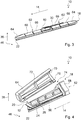
- Fig. 3 shows the windshield wiper blade device 10 according to the invention in an assembled state.
- Fig. 3 an inventive wiper blade with the windshield wiper device according to the invention 10.
- the spoiler unit 18 is formed of several parts.
- the spoiler unit 18 encloses the spring rail 12 and the fastening unit 20 almost completely in the assembled state.
- the spoiler unit 18 includes an adapter spoiler 60, a center spoiler 62 and an end spoiler 64.
- the adapter spoiler 60, the center spoiler 62 and the end spoiler 64 are hereinafter referred to as spoiler segments 60, 62, 64 for the sake of simplicity.
- the spoiler segments 60, 62, 64 are each formed as injection-molded components made of an inelastic plastic.
- the spoiler segments 60, 62 64 are connected to one another such that a movement of the spring rail 12 and in particular of the windshield wiper blade device 10 can take place unhindered.
- the adapter spoiler 60 is designed to disguise the adapter 28 to a connection to the wiper arm 30. Further, the adapter spoiler 60 is intended to make a connection to the center spoiler 62.
- the center spoiler 62 is provided to cover the windshield wiper blade assembly 10 to the end spoiler 64.
- the end spoiler 64 is adapted to clad two opposite ends of the windshield wiper blade assembly 10 and complete the spoiler unit 18.
- the center spoiler 62 has an extension with a constant cross-section with respect to the longitudinal direction 14 and is formed from a plurality of modules 66, 68, of which in FIG Fig. 3 shown embodiment two are shown.
- modules 66, 68 can then be used within a modular system by combining them for different extents of wiper blades. The necessity of having to produce a complete set of spoiler segments 60, 62, 64 for each required extent of the wiper blade can thus be avoided, which reduces the effort required for production.
- an inventive wiper blade is also present when the spoiler unit 18 has a central spoiler 62 with a cross section deviating from a constant cross section and / or the middle spoiler 62 has a different number of modules.
- fastening means 70 are respectively attached to the spoiler segments 60, 62, 64 (cf. Fig. 4 ).
- the fastening means 70 are designed as snap hooks and engage in the mounted state, the spring rail 12 with respect to the vertical direction 36. It is conceivable, a determination with respect to the longitudinal direction 14 of the spoiler segments 60, 62, 64 also accomplish by means of the fastening means 70.
- the fastening means 70 could engage in corresponding fastening recesses (not shown) in the spring rail 12.
- the spoiler unit 18 has a plurality of spoiler transverse webs 72.
- the spoiler crossbars 72 are in each case in the spoiler segments 60, 62, 64 on one of the spring rail 12 facing underside of the spoiler segments 60, 62, 64 in a partial region which comes in the mounted state at the height of the region 26 of the fastening unit 20 and at the level of the recess separating webs 56 arranged. In the assembled state, therefore, the spoiler transverse webs 72 engage in the regions 26 of the fastening unit 20 formed as gaps. As a result, the fixing with respect to the longitudinal direction 14 of the spoiler unit 18 and in particular of the spoiler segments 60, 62, 64 can take place. It could thus be shown that the fastening unit 20 is intended to fix the spoiler unit 18 to the spring rail 12.
- a contact region 74 between two spoiler segments 60, 62, 64 can be realized as an overlap.
- the contact region 74 as an overlap of two spoiler segments 60, 62, 64, it is important to ensure that free spaces are made large enough so that movement of the spring rail 12 can take place unhindered.
Landscapes
- Engineering & Computer Science (AREA)
- Mechanical Engineering (AREA)
- Physics & Mathematics (AREA)
- Fluid Mechanics (AREA)
- Quality & Reliability (AREA)
- Body Structure For Vehicles (AREA)
- Ink Jet (AREA)
Claims (4)
- Dispositif de balai d'essuie-glace comprenant au moins un rail à ressort (12) qui, vu dans la direction longitudinale (14) du rail à ressort (12), présente une pluralité d'évidements (16), comprenant au moins une unité de déflecteur (18) et comprenant au moins une unité de fixation (20) réalisée de manière séparée du rail à ressort (12), laquelle, dans au moins un état monté, s'engage dans les évidements (16) du rail à ressort (12), et est prévue pour fixer une unité de raclette de balai d'essuie-glace (22) et l'unité de déflecteur (18) au rail à ressort (12), caractérisé en ce que l'unité de fixation (20) est fixée par l'unité de raclette de balai d'essuie-glace (22) dans l'état monté.
- Dispositif de balai d'essuie-glace selon la revendication 1, caractérisé en ce que l'unité de fixation (20) est réalisée sous forme de pince.
- Dispositif de balai d'essuie-glace selon l'une quelconque des revendications précédentes, caractérisé en ce que l'unité de fixation (20) présente au moins deux régions (24, 26) avec des surfaces différentes en section transversale.
- Balai d'essuie-glace comprenant un dispositif de balai d'essuie-glace (10) selon l'une quelconque des revendications précédentes.
Applications Claiming Priority (2)
| Application Number | Priority Date | Filing Date | Title |
|---|---|---|---|
| DE102012209975A DE102012209975A1 (de) | 2012-06-14 | 2012-06-14 | Scheibenwischblattvorrichtung |
| PCT/EP2013/061267 WO2013186068A1 (fr) | 2012-06-14 | 2013-05-31 | Dispositif de balai d'essuie-glace |
Publications (2)
| Publication Number | Publication Date |
|---|---|
| EP2861468A1 EP2861468A1 (fr) | 2015-04-22 |
| EP2861468B1 true EP2861468B1 (fr) | 2018-10-24 |
Family
ID=48579033
Family Applications (1)
| Application Number | Title | Priority Date | Filing Date |
|---|---|---|---|
| EP13727839.6A Active EP2861468B1 (fr) | 2012-06-14 | 2013-05-31 | Dispositif de balai d'essuie-glace |
Country Status (5)
| Country | Link |
|---|---|
| EP (1) | EP2861468B1 (fr) |
| CN (1) | CN104349951B (fr) |
| BR (1) | BR112014029350A2 (fr) |
| DE (1) | DE102012209975A1 (fr) |
| WO (1) | WO2013186068A1 (fr) |
Families Citing this family (3)
| Publication number | Priority date | Publication date | Assignee | Title |
|---|---|---|---|---|
| DE102015225947A1 (de) * | 2015-12-18 | 2017-06-22 | Robert Bosch Gmbh | Wischblattvorrichtung |
| DE102020200343A1 (de) * | 2020-01-14 | 2021-07-15 | Robert Bosch Gesellschaft mit beschränkter Haftung | Wischblattvorrichtung |
| EP4605276A1 (fr) * | 2022-10-20 | 2025-08-27 | Robert Bosch GmbH | Balai d'essuie-glace, en particulier pour un véhicule automobile |
Family Cites Families (11)
| Publication number | Priority date | Publication date | Assignee | Title |
|---|---|---|---|---|
| DE19650929C2 (de) | 1996-12-07 | 2000-02-03 | Daimler Chrysler Ag | Scheibenwischer für eine Windschutzscheibe eines Kraftfahrzeugs |
| JPWO2004054860A1 (ja) * | 2002-12-17 | 2006-04-20 | 株式会社ミツバ | ワイパブレード |
| JP3898186B2 (ja) * | 2003-02-14 | 2007-03-28 | ケーシーダブリュー コーポレーション | 車両用ワイパーブレード組立体 |
| DE102004051466A1 (de) * | 2004-05-28 | 2005-12-15 | Robert Bosch Gmbh | Wischblatt |
| WO2006088274A1 (fr) * | 2005-02-16 | 2006-08-24 | Cap Inc | Balai d'essuie-glace pour automobile |
| US7150066B1 (en) * | 2005-06-15 | 2006-12-19 | Shih Hsien Huang | Windshield wiper structure for vehicles |
| TWM323417U (en) * | 2007-06-01 | 2007-12-11 | Yu-Rung Lin | Non-supporting windshield wiper |
| FR2923785B1 (fr) * | 2007-11-19 | 2009-12-25 | Valeo Systemes Dessuyage | Balai d'essuyage pour vitres de vehicule. |
| DE102007056321A1 (de) * | 2007-11-22 | 2009-11-26 | Robert Bosch Gmbh | Wischblatt |
| CN201169250Y (zh) * | 2008-03-07 | 2008-12-24 | 汪新军 | 雨刷 |
| US8028368B2 (en) * | 2008-07-09 | 2011-10-04 | Unipoint Electric Mfg. Co., Ltd. | Windshield wiper |
-
2012
- 2012-06-14 DE DE102012209975A patent/DE102012209975A1/de not_active Ceased
-
2013
- 2013-05-31 WO PCT/EP2013/061267 patent/WO2013186068A1/fr not_active Ceased
- 2013-05-31 EP EP13727839.6A patent/EP2861468B1/fr active Active
- 2013-05-31 BR BR112014029350A patent/BR112014029350A2/pt active Search and Examination
- 2013-05-31 CN CN201380030956.XA patent/CN104349951B/zh not_active Expired - Fee Related
Non-Patent Citations (1)
| Title |
|---|
| None * |
Also Published As
| Publication number | Publication date |
|---|---|
| WO2013186068A1 (fr) | 2013-12-19 |
| BR112014029350A2 (pt) | 2017-06-27 |
| CN104349951B (zh) | 2016-11-16 |
| EP2861468A1 (fr) | 2015-04-22 |
| CN104349951A (zh) | 2015-02-11 |
| DE102012209975A1 (de) | 2013-12-19 |
Similar Documents
| Publication | Publication Date | Title |
|---|---|---|
| EP0929423B1 (fr) | Raclette d'essuie-glace pour vitres de vehicules automobiles | |
| EP2162321B1 (fr) | Balai d'essuie-glace plat | |
| EP1648749B1 (fr) | Dispositif d'essuyage | |
| WO2003080409A1 (fr) | Dispositif d'essuie-glace comprenant un balai d'essuie-glace plat et un bras d'essuie-glace | |
| DE102008000708A1 (de) | Wischblatt | |
| WO2012013303A1 (fr) | Dispositif de fixation pour un profilé en une matière plastique renforcée par des fibres | |
| EP0847346B1 (fr) | Lame d'essuie-glace a brise-vent pour systemes essuie-glace de vehicules a moteur | |
| DE102011078163A1 (de) | Wischblattvorrichtung | |
| EP2861468B1 (fr) | Dispositif de balai d'essuie-glace | |
| WO2015018912A1 (fr) | Dispositif de fixation par clipsage, en particulier pour véhicules à moteur | |
| DE102012209304A1 (de) | Wischblattvorrichtung | |
| DE102015218682A1 (de) | Wischblattvorrichtung | |
| DE112014003093B4 (de) | Universalverbindungsanordnung | |
| WO2014180756A1 (fr) | Dispositif d'essuyage | |
| DE102015211045B4 (de) | Frontendmodul für ein Kraftfahrzeug sowie Anordnung eines solchen Frontendmoduls an einem Montageträger eines Kraftfahrzeugs | |
| DE102005059730A1 (de) | Wischeranordnung für Fahrzeugscheiben sowie Spoilerelement zur Verwendung bei einer Wischeranordnung | |
| DE112014005717T5 (de) | Endkappe für eine Wischeranordnung | |
| DE112014005511T5 (de) | Endkappe zur Fixierung eines Wischelements eines Scheibenwischers | |
| DE19959259B4 (de) | Wischblatt zum Reinigen von Scheiben an Kraftfahrzeugen | |
| EP2540583B1 (fr) | Dispositif de raclette d'essuie-glace | |
| DE112014005272T5 (de) | Verriegelungskopplung für Scheibenwischeranlage | |
| DE102012211055A1 (de) | Wischblattvorrichtung | |
| DE102011076389A1 (de) | Wischblattvorrichtung | |
| DE102016010696A1 (de) | Wischeranordnung für eine Fahrzeugscheibe | |
| DE102011076380B4 (de) | Wischblattvorrichtung |
Legal Events
| Date | Code | Title | Description |
|---|---|---|---|
| PUAI | Public reference made under article 153(3) epc to a published international application that has entered the european phase |
Free format text: ORIGINAL CODE: 0009012 |
|
| 17P | Request for examination filed |
Effective date: 20150114 |
|
| AK | Designated contracting states |
Kind code of ref document: A1 Designated state(s): AL AT BE BG CH CY CZ DE DK EE ES FI FR GB GR HR HU IE IS IT LI LT LU LV MC MK MT NL NO PL PT RO RS SE SI SK SM TR |
|
| AX | Request for extension of the european patent |
Extension state: BA ME |
|
| DAX | Request for extension of the european patent (deleted) | ||
| GRAP | Despatch of communication of intention to grant a patent |
Free format text: ORIGINAL CODE: EPIDOSNIGR1 |
|
| STAA | Information on the status of an ep patent application or granted ep patent |
Free format text: STATUS: GRANT OF PATENT IS INTENDED |
|
| INTG | Intention to grant announced |
Effective date: 20180711 |
|
| GRAS | Grant fee paid |
Free format text: ORIGINAL CODE: EPIDOSNIGR3 |
|
| GRAA | (expected) grant |
Free format text: ORIGINAL CODE: 0009210 |
|
| STAA | Information on the status of an ep patent application or granted ep patent |
Free format text: STATUS: THE PATENT HAS BEEN GRANTED |
|
| AK | Designated contracting states |
Kind code of ref document: B1 Designated state(s): AL AT BE BG CH CY CZ DE DK EE ES FI FR GB GR HR HU IE IS IT LI LT LU LV MC MK MT NL NO PL PT RO RS SE SI SK SM TR |
|
| REG | Reference to a national code |
Ref country code: CH Ref legal event code: EP |
|
| REG | Reference to a national code |
Ref country code: IE Ref legal event code: FG4D Free format text: LANGUAGE OF EP DOCUMENT: GERMAN |
|
| REG | Reference to a national code |
Ref country code: AT Ref legal event code: REF Ref document number: 1056302 Country of ref document: AT Kind code of ref document: T Effective date: 20181115 |
|
| REG | Reference to a national code |
Ref country code: DE Ref legal event code: R096 Ref document number: 502013011427 Country of ref document: DE |
|
| REG | Reference to a national code |
Ref country code: NL Ref legal event code: MP Effective date: 20181024 |
|
| REG | Reference to a national code |
Ref country code: LT Ref legal event code: MG4D |
|
| PG25 | Lapsed in a contracting state [announced via postgrant information from national office to epo] |
Ref country code: NL Free format text: LAPSE BECAUSE OF FAILURE TO SUBMIT A TRANSLATION OF THE DESCRIPTION OR TO PAY THE FEE WITHIN THE PRESCRIBED TIME-LIMIT Effective date: 20181024 |
|
| PG25 | Lapsed in a contracting state [announced via postgrant information from national office to epo] |
Ref country code: FI Free format text: LAPSE BECAUSE OF FAILURE TO SUBMIT A TRANSLATION OF THE DESCRIPTION OR TO PAY THE FEE WITHIN THE PRESCRIBED TIME-LIMIT Effective date: 20181024 Ref country code: IS Free format text: LAPSE BECAUSE OF FAILURE TO SUBMIT A TRANSLATION OF THE DESCRIPTION OR TO PAY THE FEE WITHIN THE PRESCRIBED TIME-LIMIT Effective date: 20190224 Ref country code: BG Free format text: LAPSE BECAUSE OF FAILURE TO SUBMIT A TRANSLATION OF THE DESCRIPTION OR TO PAY THE FEE WITHIN THE PRESCRIBED TIME-LIMIT Effective date: 20190124 Ref country code: PL Free format text: LAPSE BECAUSE OF FAILURE TO SUBMIT A TRANSLATION OF THE DESCRIPTION OR TO PAY THE FEE WITHIN THE PRESCRIBED TIME-LIMIT Effective date: 20181024 Ref country code: HR Free format text: LAPSE BECAUSE OF FAILURE TO SUBMIT A TRANSLATION OF THE DESCRIPTION OR TO PAY THE FEE WITHIN THE PRESCRIBED TIME-LIMIT Effective date: 20181024 Ref country code: LV Free format text: LAPSE BECAUSE OF FAILURE TO SUBMIT A TRANSLATION OF THE DESCRIPTION OR TO PAY THE FEE WITHIN THE PRESCRIBED TIME-LIMIT Effective date: 20181024 Ref country code: ES Free format text: LAPSE BECAUSE OF FAILURE TO SUBMIT A TRANSLATION OF THE DESCRIPTION OR TO PAY THE FEE WITHIN THE PRESCRIBED TIME-LIMIT Effective date: 20181024 Ref country code: NO Free format text: LAPSE BECAUSE OF FAILURE TO SUBMIT A TRANSLATION OF THE DESCRIPTION OR TO PAY THE FEE WITHIN THE PRESCRIBED TIME-LIMIT Effective date: 20190124 Ref country code: LT Free format text: LAPSE BECAUSE OF FAILURE TO SUBMIT A TRANSLATION OF THE DESCRIPTION OR TO PAY THE FEE WITHIN THE PRESCRIBED TIME-LIMIT Effective date: 20181024 |
|
| PG25 | Lapsed in a contracting state [announced via postgrant information from national office to epo] |
Ref country code: PT Free format text: LAPSE BECAUSE OF FAILURE TO SUBMIT A TRANSLATION OF THE DESCRIPTION OR TO PAY THE FEE WITHIN THE PRESCRIBED TIME-LIMIT Effective date: 20190224 Ref country code: RS Free format text: LAPSE BECAUSE OF FAILURE TO SUBMIT A TRANSLATION OF THE DESCRIPTION OR TO PAY THE FEE WITHIN THE PRESCRIBED TIME-LIMIT Effective date: 20181024 Ref country code: GR Free format text: LAPSE BECAUSE OF FAILURE TO SUBMIT A TRANSLATION OF THE DESCRIPTION OR TO PAY THE FEE WITHIN THE PRESCRIBED TIME-LIMIT Effective date: 20190125 Ref country code: AL Free format text: LAPSE BECAUSE OF FAILURE TO SUBMIT A TRANSLATION OF THE DESCRIPTION OR TO PAY THE FEE WITHIN THE PRESCRIBED TIME-LIMIT Effective date: 20181024 Ref country code: SE Free format text: LAPSE BECAUSE OF FAILURE TO SUBMIT A TRANSLATION OF THE DESCRIPTION OR TO PAY THE FEE WITHIN THE PRESCRIBED TIME-LIMIT Effective date: 20181024 |
|
| REG | Reference to a national code |
Ref country code: DE Ref legal event code: R097 Ref document number: 502013011427 Country of ref document: DE |
|
| PG25 | Lapsed in a contracting state [announced via postgrant information from national office to epo] |
Ref country code: IT Free format text: LAPSE BECAUSE OF FAILURE TO SUBMIT A TRANSLATION OF THE DESCRIPTION OR TO PAY THE FEE WITHIN THE PRESCRIBED TIME-LIMIT Effective date: 20181024 Ref country code: CZ Free format text: LAPSE BECAUSE OF FAILURE TO SUBMIT A TRANSLATION OF THE DESCRIPTION OR TO PAY THE FEE WITHIN THE PRESCRIBED TIME-LIMIT Effective date: 20181024 Ref country code: DK Free format text: LAPSE BECAUSE OF FAILURE TO SUBMIT A TRANSLATION OF THE DESCRIPTION OR TO PAY THE FEE WITHIN THE PRESCRIBED TIME-LIMIT Effective date: 20181024 |
|
| PG25 | Lapsed in a contracting state [announced via postgrant information from national office to epo] |
Ref country code: EE Free format text: LAPSE BECAUSE OF FAILURE TO SUBMIT A TRANSLATION OF THE DESCRIPTION OR TO PAY THE FEE WITHIN THE PRESCRIBED TIME-LIMIT Effective date: 20181024 Ref country code: SM Free format text: LAPSE BECAUSE OF FAILURE TO SUBMIT A TRANSLATION OF THE DESCRIPTION OR TO PAY THE FEE WITHIN THE PRESCRIBED TIME-LIMIT Effective date: 20181024 Ref country code: SK Free format text: LAPSE BECAUSE OF FAILURE TO SUBMIT A TRANSLATION OF THE DESCRIPTION OR TO PAY THE FEE WITHIN THE PRESCRIBED TIME-LIMIT Effective date: 20181024 Ref country code: RO Free format text: LAPSE BECAUSE OF FAILURE TO SUBMIT A TRANSLATION OF THE DESCRIPTION OR TO PAY THE FEE WITHIN THE PRESCRIBED TIME-LIMIT Effective date: 20181024 |
|
| PLBE | No opposition filed within time limit |
Free format text: ORIGINAL CODE: 0009261 |
|
| STAA | Information on the status of an ep patent application or granted ep patent |
Free format text: STATUS: NO OPPOSITION FILED WITHIN TIME LIMIT |
|
| 26N | No opposition filed |
Effective date: 20190725 |
|
| PG25 | Lapsed in a contracting state [announced via postgrant information from national office to epo] |
Ref country code: SI Free format text: LAPSE BECAUSE OF FAILURE TO SUBMIT A TRANSLATION OF THE DESCRIPTION OR TO PAY THE FEE WITHIN THE PRESCRIBED TIME-LIMIT Effective date: 20181024 |
|
| REG | Reference to a national code |
Ref country code: CH Ref legal event code: PL |
|
| GBPC | Gb: european patent ceased through non-payment of renewal fee |
Effective date: 20190531 |
|
| PG25 | Lapsed in a contracting state [announced via postgrant information from national office to epo] |
Ref country code: CH Free format text: LAPSE BECAUSE OF NON-PAYMENT OF DUE FEES Effective date: 20190531 Ref country code: MC Free format text: LAPSE BECAUSE OF FAILURE TO SUBMIT A TRANSLATION OF THE DESCRIPTION OR TO PAY THE FEE WITHIN THE PRESCRIBED TIME-LIMIT Effective date: 20181024 Ref country code: LI Free format text: LAPSE BECAUSE OF NON-PAYMENT OF DUE FEES Effective date: 20190531 |
|
| REG | Reference to a national code |
Ref country code: BE Ref legal event code: MM Effective date: 20190531 |
|
| PG25 | Lapsed in a contracting state [announced via postgrant information from national office to epo] |
Ref country code: LU Free format text: LAPSE BECAUSE OF NON-PAYMENT OF DUE FEES Effective date: 20190531 |
|
| PG25 | Lapsed in a contracting state [announced via postgrant information from national office to epo] |
Ref country code: TR Free format text: LAPSE BECAUSE OF FAILURE TO SUBMIT A TRANSLATION OF THE DESCRIPTION OR TO PAY THE FEE WITHIN THE PRESCRIBED TIME-LIMIT Effective date: 20181024 |
|
| PG25 | Lapsed in a contracting state [announced via postgrant information from national office to epo] |
Ref country code: IE Free format text: LAPSE BECAUSE OF NON-PAYMENT OF DUE FEES Effective date: 20190531 Ref country code: GB Free format text: LAPSE BECAUSE OF NON-PAYMENT OF DUE FEES Effective date: 20190531 |
|
| PG25 | Lapsed in a contracting state [announced via postgrant information from national office to epo] |
Ref country code: BE Free format text: LAPSE BECAUSE OF NON-PAYMENT OF DUE FEES Effective date: 20190531 |
|
| PG25 | Lapsed in a contracting state [announced via postgrant information from national office to epo] |
Ref country code: FR Free format text: LAPSE BECAUSE OF NON-PAYMENT OF DUE FEES Effective date: 20190531 |
|
| REG | Reference to a national code |
Ref country code: AT Ref legal event code: MM01 Ref document number: 1056302 Country of ref document: AT Kind code of ref document: T Effective date: 20190531 |
|
| PG25 | Lapsed in a contracting state [announced via postgrant information from national office to epo] |
Ref country code: AT Free format text: LAPSE BECAUSE OF NON-PAYMENT OF DUE FEES Effective date: 20190531 |
|
| PG25 | Lapsed in a contracting state [announced via postgrant information from national office to epo] |
Ref country code: CY Free format text: LAPSE BECAUSE OF FAILURE TO SUBMIT A TRANSLATION OF THE DESCRIPTION OR TO PAY THE FEE WITHIN THE PRESCRIBED TIME-LIMIT Effective date: 20181024 |
|
| PG25 | Lapsed in a contracting state [announced via postgrant information from national office to epo] |
Ref country code: HU Free format text: LAPSE BECAUSE OF FAILURE TO SUBMIT A TRANSLATION OF THE DESCRIPTION OR TO PAY THE FEE WITHIN THE PRESCRIBED TIME-LIMIT; INVALID AB INITIO Effective date: 20130531 Ref country code: MT Free format text: LAPSE BECAUSE OF FAILURE TO SUBMIT A TRANSLATION OF THE DESCRIPTION OR TO PAY THE FEE WITHIN THE PRESCRIBED TIME-LIMIT Effective date: 20181024 |
|
| PG25 | Lapsed in a contracting state [announced via postgrant information from national office to epo] |
Ref country code: MK Free format text: LAPSE BECAUSE OF FAILURE TO SUBMIT A TRANSLATION OF THE DESCRIPTION OR TO PAY THE FEE WITHIN THE PRESCRIBED TIME-LIMIT Effective date: 20181024 |
|
| PGFP | Annual fee paid to national office [announced via postgrant information from national office to epo] |
Ref country code: DE Payment date: 20250716 Year of fee payment: 13 |