EP2862431A1 - Dosiereinrichtung zum Dosieren von Schüttgut - Google Patents
Dosiereinrichtung zum Dosieren von Schüttgut Download PDFInfo
- Publication number
- EP2862431A1 EP2862431A1 EP20130188884 EP13188884A EP2862431A1 EP 2862431 A1 EP2862431 A1 EP 2862431A1 EP 20130188884 EP20130188884 EP 20130188884 EP 13188884 A EP13188884 A EP 13188884A EP 2862431 A1 EP2862431 A1 EP 2862431A1
- Authority
- EP
- European Patent Office
- Prior art keywords
- flap
- bulk material
- deflecting
- metering device
- opening
- Prior art date
- Legal status (The legal status is an assumption and is not a legal conclusion. Google has not performed a legal analysis and makes no representation as to the accuracy of the status listed.)
- Granted
Links
Images


Classifications
-
- A—HUMAN NECESSITIES
- A01—AGRICULTURE; FORESTRY; ANIMAL HUSBANDRY; HUNTING; TRAPPING; FISHING
- A01C—PLANTING; SOWING; FERTILISING
- A01C7/00—Sowing
- A01C7/08—Broadcast seeders; Seeders depositing seeds in rows
- A01C7/10—Devices for adjusting the seed-box ; Regulation of machines for depositing quantities at intervals
- A01C7/107—Calibration of the seed rate
-
- A—HUMAN NECESSITIES
- A01—AGRICULTURE; FORESTRY; ANIMAL HUSBANDRY; HUNTING; TRAPPING; FISHING
- A01C—PLANTING; SOWING; FERTILISING
- A01C7/00—Sowing
- A01C7/08—Broadcast seeders; Seeders depositing seeds in rows
- A01C7/12—Seeders with feeding wheels
- A01C7/123—Housings for feed rollers or wheels
- A01C7/124—Housings for feed rollers or wheels with top delivery of the seeds
-
- A—HUMAN NECESSITIES
- A01—AGRICULTURE; FORESTRY; ANIMAL HUSBANDRY; HUNTING; TRAPPING; FISHING
- A01C—PLANTING; SOWING; FERTILISING
- A01C7/00—Sowing
- A01C7/08—Broadcast seeders; Seeders depositing seeds in rows
- A01C7/081—Seeders depositing seeds in rows using pneumatic means
-
- A—HUMAN NECESSITIES
- A01—AGRICULTURE; FORESTRY; ANIMAL HUSBANDRY; HUNTING; TRAPPING; FISHING
- A01C—PLANTING; SOWING; FERTILISING
- A01C7/00—Sowing
- A01C7/08—Broadcast seeders; Seeders depositing seeds in rows
- A01C7/12—Seeders with feeding wheels
- A01C7/127—Cell rollers, wheels, discs or belts
Definitions
- the present invention relates to a metering device for metering free-flowing bulk material, in particular seed and / or fertilizer, from a container according to claim 1 and a distributor for discharging free-flowing bulk material, in particular seed and / or fertilizer, with a metering device according to claim 8.
- Such dosing devices are used in agricultural machinery to dose seed and / or fertilizer precisely and then deploy on agricultural land, such as in the EP 0 094 583 described.
- the DE 10 2007 044 178 A1 shows a pneumatic seed drill with a metering device. This has a Abwindprobenö réelle with a Abmosprobenö réelle releasing, inclined to the lower edge of the opening guide flap for discharging the metered seed for the calibration test.
- Object of the present invention is to provide a metering device with which the function of the metering device is optimized, in particular with regard to the accessibility and functionality for taking a calibration test.
- the invention is based on the idea of integrating a flap mechanism into the conveyor channel in such a way that it is easy to operate and works without any problems.
- the flap mechanism has two separate, but in particular mechanically connected, flaps in the form of a deflecting flap and an opening flap.
- the deflecting flap By the deflecting flap having its free end in a conveying direction of the bulk material, a gentle deflection of the bulk material can take place. Furthermore, the deflecting flap can simultaneously be formed as a wall of the conveying channel, in particular flush with the conveying channel. In addition, a seal of the delivery channel is easier to achieve. In particular, the deflecting flap has only one degree of freedom about the pivot axis.
- the metering device is further developed by the deflecting flap is struck in the delivery channel opposite to the opening flap.
- the flap mechanism is designed so that the opening flap and the deflecting flap can be actuated together via a mechanical connecting element, the operation is facilitated and precluded incorrect operation.
- the pressure equalizing means may comprise at least one diaphragm-provided pressure equalization port.
- the opening behavior of the membrane is advantageously precisely adjustable, in particular by a suitable choice of material and / or its thickness and area and / or the shape and / or dimensions of the membrane.
- the membrane is particularly durable by selecting the adapted to the operating conditions membrane material.
- the opening cross section of a membrane is larger compared with a possible valve solution, so that a direct and improved pressure equalization is possible.
- the pressure compensation means at a pressure difference, in particular at a negative pressure in the conveyor channel, of at least 1 mbar, in particular at least 5 mbar, preferably at least 10 mbar, more preferably at least 15 mbar, are actuated.
- the metering device can be solved in a particularly simple design by the pressure compensation means are formed passive acting.
- the pressure compensation means are designed to work automatically and are triggered by a specific, present in the delivery channel to the environment pressure difference.
- the pressure compensation means are closed at a pressure difference of less than 15 mbar, in particular less than 10 mbar, preferably less than 5 mbar, more preferably less than 1 mbar. Closed means that no pressure equalization between the delivery channel and the environment takes place, wherein the pressure compensation means are formed in particular the delivery channel relative to the environment sealing.
- flap mechanism for deflecting the flowable bulk material, in particular seed and / or fertilizer, arranged to a Abwindprobenö Stamm.
- a distributor for discharging free-flowing bulk material, in particular seed and / or fertilizer disclosed with a prescribed metering device, wherein all features of the metering device also apply to the distributor.
- FIG. 1 is a container 11 for receiving free-flowing bulk material, in particular seed or fertilizer, indicated with a bottom 10, at its bottom via fastening means 6, a metering device 1 is fixed such that an inlet 8 of the metering device 1 is arranged in the region of a bottom opening 5.
- the bottom opening 5 can be closed by a slide 4.
- seed is conveyed out of the container 11 through a delivery channel 9 from the inlet 8 to a metering outlet 7 arranged at the opposite end of the delivery channel 9.
- the metering and delivery is carried out by a projecting at least partially in the conveyor channel 9 feed wheel 3.
- the metering 7 opens at a pneumatically operated conveyor line 14, from where the bulk material is distributed over not shown distributor to coulters of the distributor.
- the operation of the metering device 1 during the discharge of free-flowing bulk material, in particular seed and / or fertilizer, can be best in FIG. 6 recognize and describe.
- the task of the metering wheel 3 is to bring a certain amount of bulk material from the container 11 to the delivery line 14, the delivery rate being determined by the rotational speed of the delivery wheel 3 and its geometrical dimensions, in particular on circumferentially arranged delivery cams.
- the flow rate in particular exclusively, be controlled by the rotational speed of the feed wheel 3.
- a slider 26 may be provided for closing the bottom opening 5.
- the delivery line 14 is arranged transversely to the delivery channel 9 on the metering 7.
- the pressure conditions in the Abdrehabites and in the pressure compensation section are affected, since the two aforementioned sections are preferably sealed to the environment, especially in a conveying position of the flap mechanism 12 (see FIG. 6 ).
- the flap mechanism 12 has an opening flap 15 for opening a calibration sample opening 19 of the delivery channel 9 in order to remove a calibration sample from the delivery stream or to redirect the delivery stream accordingly.
- a deflecting flap 16 is provided, which is in particular actuated together with the opening flap 15, preferably via a mechanical connecting element 17. In this way, a second conveying path is defined.
- the first and the second conveyor line are identical in the inlet section and in the conveyor wheel section and branch in the calibration sample section, in particular by the deflecting flap 16.
- the opening flap 15 has a pivot axis 15a about which the opening flap 15 is pivotable from a closed to an open position.
- a wall section 15w of the opening flap 15 forms part of an inner wall of the conveyor channel, in particular flush and / or in alignment with the conveyor channel 9.
- the deflecting flap 16 likewise has a pivot axis 16a about which the deflecting flap 16 can be pivoted from a calibration sampling position of the deflecting flap 16 into a conveying position of the deflecting flap 16. In the calibration test position, the metering device is in the calibration test position.
- the deflecting flap 16 is arranged such that a free end 16e of the deflecting flap 16 points in the conveying direction of the respective conveying path of the bulk material.
- the pivot axis 16a is arranged closer to the feed wheel 3 than the end 16e, which in particular points away from the feed wheel 3.
- the deflection flap 16 is dimensioned such that in the calibration rotational position it abuts against a side edge 18 of a calibration sample opening 19 of the delivery channel 9 with its end 16e opposite the pivot axis 16a.
- the deflecting flap 19 extends obliquely through the conveying channel 9, so that the bulk material for the calibration test for Abcardprobenö réelle 19 are deflected out. This is achieved structurally in that the pivot axis 16a of the deflecting flap 16 is arranged closer to the conveying wheel 3 than the end 16e.
- the flap mechanism 12 is realized in particular by a toggle lever 20 as a mechanical connecting element 17 which, in particular mechanically, can be actuated from outside the metering device 1, in particular against a spring 21 caused by a spring 21, the opening flap 15 and the deflecting flap 16 connecting spring 21 caused spring force.
- the pressure compensation means 2 are by means of a housing member 22 on the metering device 1, in particular sealed, mounted, in particular mechanically flanged. Furthermore, membranes 23 are provided on membrane openings 24 of the housing element 22 on the housing element 22, in particular two oppositely arranged membranes. The membrane openings 24 are arranged in particular parallel to one another in alignment and / or parallel to the delivery line 14.
- a single diaphragm 23 attached to the housing member may be sufficient.
- the membranes 23 are attached to struts 25, in particular concentrically to the respective membrane opening 24.
- the membranes 23 are made of a flexible material, in particular of an elastomeric character, preferably an elastomer, such as rubber, alternatively of a thermoplastic elastomer. Due to the, preferably circular in cross-section, shape of the membrane and only centric fixation, the diaphragm 23 deformed at a pressure difference between the conveyor channel 9 and the environment inwardly into the interior of the housing member 22. Thus, through the diaphragm opening 24, a pressure equalization take place (see Arrows in FIG. 5 ). Once a pressure equalization has taken place, the membranes 23 close the Membrane openings 24 due to the elasticity of the membranes 23 automatically. According to the invention, the pressure compensation means 2 are automatically controlled by the pressure conditions in the delivery channel 9, in particular in the pressure equalization section.
- the membrane should open in particular at a negative pressure of about 10 mbar, for example, can then rest in the delivery channel 9, if on the delivery line 14 an air flow is applied, but the feed wheel 3 is stationary.
- a negative pressure of about 10 mbar
- the membrane should open in particular at a negative pressure of about 10 mbar, for example, can then rest in the delivery channel 9, if on the delivery line 14 an air flow is applied, but the feed wheel 3 is stationary.
- This can be the case, for example, if no bulk material is to be spread on the headland.
- the case may occur when a calibration test is taken over the flap mechanism 12, whereby in the closed by the deflecting flap 16 pressure compensation region due to the delivery line 14, a negative pressure may occur.
- the invention in particular ensures that after stopping the feed wheel 3 (for example, at the headland, where no bulk material to be applied) despite continued operation of the feed line 14 no negative pressure applied to the feed wheel 3, since the membrane (s) 23 automatically for provide a pressure equalization.
Landscapes
- Life Sciences & Earth Sciences (AREA)
- Soil Sciences (AREA)
- Environmental Sciences (AREA)
- Weight Measurement For Supplying Or Discharging Of Specified Amounts Of Material (AREA)
- Fertilizing (AREA)
- Sowing (AREA)
- Filling Or Emptying Of Bunkers, Hoppers, And Tanks (AREA)
Abstract
Description
- Die vorliegende Erfindung betrifft eine Dosiereinrichtung zum Dosieren von rieselfähigem Schüttgut, insbesondere Saatgut und/oder Dünger, aus einem Behälter gemäß Patentanspruch 1 sowie einer Verteilmaschine zum Ausbringen von rieselfähigem Schüttgut, insbesondere Saatgut und/oder Dünger, mit einer Dosiereinrichtung gemäß Patentanspruch 8.
- Derartige Dosiergeräte werden bei landwirtschaftlichen Maschinen eingesetzt, um Saatgut und/oder Dünger präzise zu dosieren und anschließend auf landwirtschaftlichen Flächen auszubringen, wie beispielsweise in der
EP 0 094 583 beschrieben. - Die
DE 10 2007 044 178 A1 zeigt eine pneumatisch Sämaschine mit einer Dosiereinrichtung auf. Dies weist eine Abdrehprobenöffnung auf mit einer die Abdrehprobenöffnung freigebenden, zum unteren Öffnungsrand geneigten Leitklappe zum Ausleiten des dosierten Saatguts für die Abdrehprobe. - Aufgabe der vorliegenden Erfindung ist es, eine Dosiereinrichtung anzugeben, mit der die Funktion der Dosiereinrichtung optimiert wird, insbesondere hinsichtlich der Zugänglichkeit und Funktionalität zur Entnahme einer Abdrehprobe.
- Diese Aufgabe wird mit den Merkmalen der Patentansprüche 1 und 8 erfüllt. Vorteilhafte Weiterbildungen der Erfindung sind in den Unteransprüchen angegeben. In den Rahmen der Erfindung fallen auch sämtliche Kombinationen aus zumindest zwei von in der Beschreibung, den Ansprüchen und/oder den Figuren angegebenen Merkmalen. Bei angegebenen Wertebereichen sollen auch innerhalb der genannten Grenzen liegende Werte als Grenzwerte offenbart und in beliebiger Kombination beanspruchbar sein.
- Der Erfindung liegt der Gedanke zugrunde, einen Klappenmechanismus derart in den Förderkanal zu integrieren, dass dieser einfach zu bedienen ist und störungsfrei arbeitet. Hierzu weist der Klappenmechanismus zwei separate, insbesondere aber mechanisch verbundene, Klappen in Form einer Umlenkklappe und einer Öffnungsklappe auf.
- Dies ist insbesondere in Verbindung mit Druckausgleichsmitteln zum Ausgleich eines etwaigen Druckunterschieds zwischen dem Förderkanal und der Umgebung sinnvoll, da durch die Umlenkklappe gleichzeitig eine Abdichtung des Förderkanals gegenüber den Druckausgleichsmitteln ermöglicht wird.
- Indem die Umlenkklappe mit ihrem freien Ende in einer Förderrichtung des Schüttguts weist, kann eine schonende Umlenkung des Schüttgutes erfolgen. Weiterhin kann die Umlenkklappe gleichzeitig als Wand des Förderkanals, insbesondere bündig zum Förderkanal, ausgebildet werden. Darüber hinaus ist eine Abdichtung des Förderkanals leichter realisierbar. Insbesondere weist die Umlenkklappe ausschließlich einen Freiheitsgrad um die Schwenkachse auf.
- Die Dosiereinrichtung wird weitergebildet, indem die Umlenkklappe im Förderkanal gegenüberliegend zur Öffnungsklappe angeschlagen ist.
- Soweit der Klappenmechanismus so ausgebildet ist, dass die Öffnungsklappe und die Umlenkklappe über ein mechanisches Verbindungselement gemeinsam betätigbar sind, wird die Bedienung erleichtert und eine Fehlbedienung ausgeschlossen.
- Die Druckausgleichsmittel können mindestens eine mit einer Membran versehene Druckausgleichsöffnung umfassen. Das Öffnungsverhalten der Membran ist in vorteilhafter Weise exakt einstellbar, insbesondere durch eine geeignete Materialwahl und/oder deren dessen -stärke und -fläche und/oder die Form und/oder Abmessungen der Membran. Die Membran ist durch Auswahl des an die Betriebsbedingungen angepassten Membranmaterials besonders langlebig. Darüber hinaus ist der Öffnungsquerschnitt einer Membran verglichen mit einer etwaigen Ventillösung größer, so dass ein unmittelbarer und verbesserter Druckausgleich möglich ist.
- Gemäß einer weiteren, vorteilhaften Ausführungsform der Erfindung ist vorgesehen, dass die Druckausgleichsmittel bei einem Druckunterschied, insbesondere bei einem Unterdruck im Förderkanal, von mindestens 1 mbar, insbesondere mindestens 5 mbar, vorzugsweise mindestens 10 mbar, noch bevorzugter mindestens 15 mbar, betätigt werden.
- Gemäß der vorliegenden Erfindung kann die Dosiereinrichtung besonders einfach konstruktiv gelöst werden, indem die Druckausgleichsmittel passiv wirkend ausgebildet sind. Mit anderen Worten: Die Druckausgleichsmittel sind selbsttätig arbeitend konstruiert und werden durch einen bestimmten, im Förderkanal gegenüber der Umgebung vorliegenden Druckunterschied ausgelöst.
- Gemäß einer weiteren vorteilhaften Ausführungsform ist vorgesehen, dass die Druckausgleichsmittel bei einem Druckunterschied von weniger als 15 mbar, insbesondere weniger als 10 mbar, vorzugsweise weniger als 5 mbar, noch bevorzugter weniger als 1 mbar geschlossen sind. Geschlossen heißt, dass kein Druckausgleich zwischen dem Förderkanal und der Umgebung stattfindet, wobei die Druckausgleichsmittel insbesondere den Förderkanal gegenüber der Umgebung abdichtend ausgebildet sind.
- Gemäß einem weiteren Aspekt der vorliegenden Erfindung ist im Förderkanal zwischen dem Zulauf und den Druckausgleichsmitteln ein von außerhalb des Förderkanals betätigbarer, insbesondere gegenüber den Druckausgleichsmitteln dicht ausgebildeter, Klappenmechanismus zur Umlenkung des rieselfähigen Schüttguts, insbesondere Saatguts und/oder Düngers, zu einer Abdrehprobenöffnung angeordnet.
- Als eigenständige Erfindung wird eine Verteilmaschine zum Ausbringen von rieselfähigem Schüttgut, insbesondere Saatgut und/oder Dünger, mit einer vorbeschriebenen Dosiereinrichtung offenbart, wobei alle Merkmale der Dosiereinrichtung auch für die Verteilmaschine gelten.
- Weiterhin wird als eigenständige Erfindung ein Verfahren mit in der vorliegenden Beschreibung offenbarten Verfahrensmerkmalen offenbart, wobei etwaige Verfahrensmerkmale auch als Vorrichtungsmerkmale und umgekehrt offenbart gelten sollen.
- Weitere Vorteile, Merkmale und Einzelheiten der Erfindung ergeben sich aus der nachfolgenden Beschreibung bevorzugter Ausführungsbeispiele sowie anhand der Zeichnungen; diese zeigen in:
- Figur 1
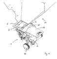
- eine schematische Perspektivansicht eines Ausschnitts einer erfindungsgemäßen Verteilmaschine,
- Figur 2
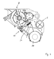
- eine schematische Seitenansicht einer erfindungsgemäßen Dosiereinrichtung,
- Figur 3
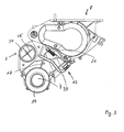
- eine schematische Seitenansicht der Dosiereinrichtung gemäß
Figur 2 von der gegenüberliegenden Seite, - Figur 4
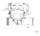
- eine schematische Seitenansicht der Dosiereinrichtung von hinten,
- Figur 5
- eine schematische Schnittansicht von Druckausgleichsmitteln der Dosiereinrichtung in Druckausgleichsposition,
- Figur 6
- eine schematische Perspektivansicht der Dosiereinrichtung in einer geschlossenen Betriebsposition eines Klappenmechanismus und
- Figur 7
- eine schematische Perspektivansicht der Dosiereinrichtung in einer geöffneten Betriebsposition des Klappenmechanismus.
- In den Figuren sind gleiche Bauteile und Bauteile mit der gleichen Funktion mit den gleichen Bezugszeichen gekennzeichnet.
- In der
Figur 1 ist ein Behälter 11 zur Aufnahme von rieselfähigem Schüttgut, insbesondere Saatgut oder Dünger, mit einem Boden 10 angedeutet, an dessen Boden über Befestigungsmittel 6 eine Dosiereinrichtung 1 derart fixierbar ist, dass ein Zulauf 8 der Dosiereinrichtung 1 im Bereich einer Bodenöffnung 5 angeordnet ist. Die Bodenöffnung 5 ist über einen Schieber 4 verschließbar. - Beim Betrieb der Dosiereinrichtung 1 wird Saatgut aus dem Behälter 11 durch einen Förderkanal 9 von dem Zulauf 8 bis zu einem am gegenüberliegenden Ende des Förderkanals 9 angeordneten Dosierabgang 7 gefördert. Die Dosierung und Förderung erfolgt durch ein zumindest teilweise in den Förderkanal 9 ragendes Förderrad 3. Der Dosierabgang 7 mündet an einer pneumatisch betriebenen Förderleitung 14, von wo aus das Schüttgut über nicht näher dargestellte Verteiler zu korrespondierenden Säscharen der Verteilmaschine verteilt wird.
- In Strömungsrichtung des Schüttguts vom Behälter 11 entlang des Förderkanals 9 verlaufend weist die Dosiereinrichtung 1 insbesondere einen oder mehrere der nachfolgenden Abschnitte, insbesondere in dieser Reihenfolge, auf:
- 1. einen Zulaufabschnitt, der sich an den Schüttgutbehälter 11 anschließt und insbesondere den Zulauf 8 umfasst, der, insbesondere unmittelbar, zum Förderrad 3 mündet;
- 2. einen das Förderrad 3 umfassenden Förderradabschnitt, in welchem der Förderkanal 9 zumindest teilweise so geformt ist, dass eine Rotationsaußenkontur des Förderrades 3 an dem Förderkanal 9 entlang verläuft;
- 3. einen Abdrehabschnitt zur Entnahme einer Abdrehprobe, insbesondere mit einem erfindungsgemäßen Klappenmechanismus 12, durch welchen der Förderkanal 9 mindestens zwei unterschiedliche Förderstrecken umfasst;
- 4. einen Druckausgleichsabschnitt mit erfindungsgemäßen Druckausgleichsmitteln 2 und
- 5. einem Förderleitungsabschnitt, an dem die Förderleitung 14, insbesondere dichtend, anordenbar, insbesondere befestigbar, ist.
- Der Betrieb der Dosiereinrichtung 1 beim Ausbringen von rieselfähigem Schüttgut, insbesondere Saatgut und/oder Dünger, lässt sich am besten in
Figur 6 erkennen und beschreiben. Aufgabe des Dosierrades 3 ist es, eine bestimmte Schüttgutmenge von dem Behälter 11 zur Förderleitung 14 zu bringen, wobei die Fördermenge durch die Rotationsgeschwindigkeit des Förderrades 3 und deren geometrische Abmessungen, insbesondere an umfangsseitig angeordneten Fördernocken, bestimmt wird. Somit kann der Förderstrom, insbesondere ausschließlich, durch die Rotationsgeschwindigkeit des Förderrades 3 gesteuert werden. Bei Stillstand des Förderrades 3 wird kein Schüttgut gefördert. Zusätzlich kann ein Schieber 26 zum Verschließen der Bodenöffnung 5 vorgesehen sein. - Sobald das Schüttgut entlang einer hierdurch definierten ersten Förderstrecke am Dosierabgang 7 ankommt, wird es von dem Luftstrom der pneumatisch betriebenen Förderleitung 14 erfasst und weitertransportiert. Insbesondere ist die Förderleitung 14 quer zum Förderkanal 9 an dem Dosierabgang 7 angeordnet.
- Durch den pneumatischen Betrieb einerseits und die kontinuierliche Zuführung von Schüttgut andererseits werden die Druckverhältnisse im Abdrehabschnitt und im Druckausgleichsabschnitt beeinflusst, da die beiden vorgenannten Abschnitte gegenüber der Umgebung vorzugsweise dicht ausgebildet sind, insbesondere in einer Förderposition des Klappenmechanismus 12 (siehe
Figur 6 ). - Der Klappenmechanismus 12 weist eine Öffnungsklappe 15 zur Öffnung einer Abdrehprobenöffnung 19 des Förderkanals 9 auf, um eine Abdrehprobe aus dem Förderstrom zu entnehmen beziehungsweise den Förderstrom entsprechend umzulenken. Zur Umlenkung ist eine Umlenkklappe 16 vorgesehen, die insbesondere gemeinsam mit der Öffnungsklappe 15 betätigt wird, vorzugsweise über ein mechanisches Verbindungselement 17. Hierdurch wird eine zweite Förderstrecke definiert.
- Der Klappenmechanismus 12 weist insbesondere zwei mögliche Betriebspositionen auf, nämlich:
- 1. Eine Abdrehprobenposition, bei der die Umlenkklappe 16 für eine Umlenkung des Schüttguts sorgt und die Öffnungsklappe 15 zur Entnahme der Abdrehprobe geöffnet ist sowie
- 2. Eine Förderposition, bei der die Umlenkklappe 16 die erste Förderstrecke wieder freigibt und die Öffnungsklappe 15 geschlossen ist.
- Die erste und die zweite Förderstrecke sind im Zulaufabschnitt und im Förderradabschnitt identisch und verzweigen im Abdrehprobenabschnitt, insbesondere durch die Umlenkklappe 16.
- Die Öffnungsklappe 15 weist eine Schwenkachse 15a auf, um welche die Öffnungsklappe 15 aus einer geschlossenen in eine geöffnete Position schwenkbar ist. In der geschlossenen Position gemäß
Figur 6 bildet ein Wandabschnitt 15w der Öffnungsklappe 15 einen Teil einer Innenwand des Förderkanals, insbesondere bündig und/oder fluchtend mit dem Förderkanal 9. - Die Umlenkklappe 16 weist ebenfalls eine Schwenkachse 16a auf, um welche die Umlenkklappe 16 aus einer Abdrehprobenstellung der Umlenkklappe 16 in eine Förderstellung der Umlenkklappe 16 schwenkbar ist. In der Abdrehprobenstellung befindet sich die Dosiereinrichtung in der Abdrehprobenposition.
- Die Umlenkklappe 16 ist so angeordnet, dass ein freies Ende 16e der Umlenkklappe 16 in Förderrichtung der jeweiligen Förderstrecke des Schüttguts weist. Mit anderen Worten: Die Schwenkachse 16a ist näher an dem Förderrad 3 angeordnet als das Ende 16e, das insbesondere vom Förderrad 3 weg weist.
- Die Umlenkklappe 16 ist so dimensioniert, dass diese in der Abdrehprobenstellung mit ihrem zur Schwenkachse 16a gegenüberliegenden Ende 16e an einer Seitenkante 18 einer Abdrehprobenöffnung 19 des Förderkanals 9 anliegt. Dabei verläuft die Umlenkklappe 19 schräg durch den Förderkanal 9, damit das Schüttgut für die Abdrehprobe zur Abdrehprobenöffnung 19 hin umgelenkt werden. Dies ist konstruktiv dadurch gelöst, dass die Schwenkachse 16a der Umlenkklappe 16 näher an dem Förderrad 3 angeordnet ist als das Ende 16e.
- Der Klappenmechanismus 12 wird insbesondere durch einen Kniehebel 20 als mechanisches Verbindungselement 17 realisiert, der, insbesondere mechanisch, von außerhalb der Dosiereinrichtung 1 betätigbar ist, insbesondere entgegen einer durch eine Feder 21 bewirkte, die Öffnungsklappe 15 und die Umlenkklappe 16 verbindende Feder 21 bewirkte Federkraft.
- Die Druckausgleichsmittel 2 sind mittels eines Gehäuseelements 22 an der Dosiereinrichtung 1, insbesondere dicht, angebracht, insbesondere mechanisch angeflanscht. Weiterhin sind an dem Gehäuseelement 22, insbesondere zwei gegenüberliegend angeordnete, Membranen 23 an Membranöffnungen 24 des Gehäuseelements 22 vorgesehen. Die Membranöffnungen 24 sind insbesondere parallel zueinander fluchtend und/oder parallel verlaufend zu der Förderleitung 14 angeordnet.
- In einer alternativen Ausführungsform kann eine einzige Membran 23, welche an dem Gehäuseelement angebracht ist, ausreichend sein.
- Die Membranen 23 sind an Streben 25, insbesondere konzentrisch zur jeweiligen Membranöffnung 24, angebracht. Die Membranen 23 bestehen aus einem flexiblen Material, insbesondere mit einem elastomeren Charakter, vorzugsweise einem Elastomer, wie zum Beispiel Kautschuk, alternativ aus einem thermoplastischen Elastomer. Durch die, vorzugsweise im Querschnitt kreisförmige, Form der Membran und ausschließlich zentrische Fixierung verformt sich die Membran 23 bei einem Druckunterschied zwischen dem Förderkanal 9 und der Umgebung nach innen in das Innere des Gehäuseelements 22. Somit kann durch die Membranöffnung 24 ein Druckausgleich stattfinden (siehe Pfeile in
Figur 5 ). Sobald ein Druckausgleich erfolgt ist, verschließen die Membranen 23 die Membranöffnungen 24 auf Grund der Elastizität der Membranen 23 selbsttätig. Die Druckausgleichsmittel 2 werden demnach erfindungsgemäß durch die Druckverhältnisse im Förderkanal 9, insbesondere in dem Druckausgleichsabschnitt, automatisch gesteuert. - Durch die Materialwahl und Materialstärke der Membranen 23 und den Öffnungsdurchmesser der Membranöffnungen 24 wird das Ansprechverhalten der Druckausgleichsmittel 2 festgelegt, wobei die Membran insbesondere bei einem Unterdruck von etwa 10 mbar öffnen soll, der beispielsweise dann in dem Förderkanal 9 anliegen kann, wenn an der Förderleitung 14 ein Luftstrom anliegt, das Förderrad 3 aber stillsteht. Dies kann beispielsweise der Fall sein, wenn an dem Vorgewende kein Schüttgut ausgebracht werden soll. Auch kann der Fall auftreten, wenn eine Abdrehprobe über den Klappenmechanismus 12 entnommen wird, wodurch in dem durch die Umlenkklappe 16 verschlossenen Druckausgleichsbereich auf Grund der Förderleitung 14 ein Unterdruck entstehen kann.
- Somit sorgt die Erfindung mit anderen Worten insbesondere dafür, dass nach Stoppen des Förderrades 3 (beispielsweise am Vorgewende, wo kein Schüttgut ausgebracht werden soll) trotz Weiterbetrieb der Förderleitung 14 kein Unterdruck an dem Förderrad 3 anliegt, da die Membran(en) 23 automatisch für einen Druckausgleich sorgen.
-
- 1
- Dosiereinrichtung
- 2
- Druckausgleichsmittel
- 3
- Förderrad
- 4
- Schieber
- 5
- Bodenöffnung
- 6
- Befestigungsmittel
- 7
- Dosierabgang
- 8
- Zulauf
- 9
- Förderkanal
- 10
- Boden
- 11
- Behälter
- 12
- Klappenmechanismus
- 13
- Auslauf
- 14
- Förderleitung
- 15
- Öffnungsklappe
- 15a
- Schwenkachse
- 15w
- Wandabschnitt
- 16
- Umlenkklappe
- 16a
- Schwenkachse
- 16e
- Ende
- 17
- Verbindungselement
- 18
- Seitenkante
- 19
- Abdrehprobenöffnung
- 20
- Kniehebel
- 21
- Feder
- 22
- Gehäuseelement
- 23
- Membranen
- 24
- Membranöffnungen
- 25
- Streben
- 26
- Schieber
Claims (8)
- Dosiereinrichtung zum Dosieren von rieselfähigem Schüttgut aus einem Behälter (11) mit- einem Förderkanal (9) mit einem Zulauf (8) und einem Dosierabgang (7) und- einem im Förderkanal (9) zwischen dem Zulauf (8) und dem Dosierabgang (7) angeordneten Klappenmechanismus (12),
dadurch gekennzeichnet, dass der Klappenmechanismus (12):- eine Umlenkklappe (16) zur Umlenkung des rieselfähigen Schüttguts zu einer Abdrehprobenöffnung (19) und- eine Öffnungsklappe (15) zur Öffnung der Abdrehprobenöffnung (19) aufweist. - Dosiereinrichtung nach Anspruch 1, bei der die Umlenkklappe (16) mit ihrem freien Ende (16e) in einer Förderrichtung des Schüttguts weist.
- Dosiereinrichtung nach Anspruch 1 oder 2, bei der die Umlenkklappe (16) im Förderkanal (9) gegenüberliegend zur Öffnungsklappe (15) angeschlagen ist.
- Dosiereinrichtung nach einem der vorhergehenden Ansprüche, bei der die Öffnungsklappe (15) und die Umlenkklappe (16) über ein mechanisches Verbindungselement (17) gemeinsam betätigbar sind.
- Dosiereinrichtung nach einem der vorhergehenden Ansprüche, bei der der Klappenmechanismus (12) durch Umschaltung von einer Förderposition der Dosiereinrichtung (1) in eine Abdrehprobenposition der Dosiereinrichtung (1) zwei Förderstrecken definiert.
- Dosiereinrichtung nach Anspruch 5, bei der der Förderkanal (9) in der Abdrehprobenposition gegenüber einem Druckausgleichsabschnitt der Dosiereinrichtung (1) dicht ausgebildet ist.
- Dosiereinrichtung nach einem der vorhergehenden Ansprüche, bei der der Klappenmechanismus (12) federbeauschlagt ist.
- Verteilmaschine zum Ausbringen von Schüttgut mit einer Dosiereinrichtung nach einem der vorhergehenden Ansprüche.
Priority Applications (4)
| Application Number | Priority Date | Filing Date | Title |
|---|---|---|---|
| PL13188884T PL2862431T3 (pl) | 2013-10-16 | 2013-10-16 | Urządzenie dozujące do dozowania materiału sypkiego |
| DK13188884.4T DK2862431T3 (en) | 2013-10-16 | 2013-10-16 | Dosing device for dosing bulk material |
| ES13188884.4T ES2564280T3 (es) | 2013-10-16 | 2013-10-16 | Dispositivo de dosificación para la dosificación de materiales a granel |
| EP13188884.4A EP2862431B1 (de) | 2013-10-16 | 2013-10-16 | Dosiereinrichtung zum Dosieren von Schüttgut |
Applications Claiming Priority (1)
| Application Number | Priority Date | Filing Date | Title |
|---|---|---|---|
| EP13188884.4A EP2862431B1 (de) | 2013-10-16 | 2013-10-16 | Dosiereinrichtung zum Dosieren von Schüttgut |
Publications (2)
| Publication Number | Publication Date |
|---|---|
| EP2862431A1 true EP2862431A1 (de) | 2015-04-22 |
| EP2862431B1 EP2862431B1 (de) | 2016-01-20 |
Family
ID=49484097
Family Applications (1)
| Application Number | Title | Priority Date | Filing Date |
|---|---|---|---|
| EP13188884.4A Active EP2862431B1 (de) | 2013-10-16 | 2013-10-16 | Dosiereinrichtung zum Dosieren von Schüttgut |
Country Status (4)
| Country | Link |
|---|---|
| EP (1) | EP2862431B1 (de) |
| DK (1) | DK2862431T3 (de) |
| ES (1) | ES2564280T3 (de) |
| PL (1) | PL2862431T3 (de) |
Cited By (1)
| Publication number | Priority date | Publication date | Assignee | Title |
|---|---|---|---|---|
| WO2020035338A1 (de) * | 2018-08-17 | 2020-02-20 | Amazonen-Werke H. Dreyer Gmbh & Co. Kg | Dosiereinrichtung für körniges gut |
Families Citing this family (2)
| Publication number | Priority date | Publication date | Assignee | Title |
|---|---|---|---|---|
| DE102020002762A1 (de) | 2020-05-08 | 2021-11-11 | Lemken Gmbh & Co. Kg | Dosiervorrichtung für eine landwirtschaftliche Maschine |
| DE102020002763A1 (de) * | 2020-05-08 | 2021-11-11 | Lemken Gmbh & Co. Kg | Dosiervorrichtung für eine landwirtschaftliche Maschine |
Citations (5)
| Publication number | Priority date | Publication date | Assignee | Title |
|---|---|---|---|---|
| EP0094583A1 (de) | 1982-05-14 | 1983-11-23 | ACCORD Landmaschinen Heinrich Weiste & Co. GmbH | Dosiergerät für Verteilersysteme für körnige Stoffe, wie Saatgut oder Dünger |
| EP0358878A2 (de) * | 1988-09-07 | 1990-03-21 | Rabewerk GmbH + Co. | Dosiervorrichtung für eine Verteilmaschine |
| DE102007044178A1 (de) | 2006-10-09 | 2008-04-10 | Rauch Landmaschinenfabrik Gmbh | Pneumatische Sämaschine |
| EP2022308A1 (de) * | 2007-08-03 | 2009-02-11 | Amazonen-Werke H. Dreyer GmbH & Co. KG | Pneumatische Verteilmaschine |
| WO2012131551A1 (en) * | 2011-03-25 | 2012-10-04 | Maschio Gapardo S.P.A. | Calibration device for agricultural (pneumatic) seed drills |
-
2013
- 2013-10-16 EP EP13188884.4A patent/EP2862431B1/de active Active
- 2013-10-16 PL PL13188884T patent/PL2862431T3/pl unknown
- 2013-10-16 DK DK13188884.4T patent/DK2862431T3/en active
- 2013-10-16 ES ES13188884.4T patent/ES2564280T3/es active Active
Patent Citations (5)
| Publication number | Priority date | Publication date | Assignee | Title |
|---|---|---|---|---|
| EP0094583A1 (de) | 1982-05-14 | 1983-11-23 | ACCORD Landmaschinen Heinrich Weiste & Co. GmbH | Dosiergerät für Verteilersysteme für körnige Stoffe, wie Saatgut oder Dünger |
| EP0358878A2 (de) * | 1988-09-07 | 1990-03-21 | Rabewerk GmbH + Co. | Dosiervorrichtung für eine Verteilmaschine |
| DE102007044178A1 (de) | 2006-10-09 | 2008-04-10 | Rauch Landmaschinenfabrik Gmbh | Pneumatische Sämaschine |
| EP2022308A1 (de) * | 2007-08-03 | 2009-02-11 | Amazonen-Werke H. Dreyer GmbH & Co. KG | Pneumatische Verteilmaschine |
| WO2012131551A1 (en) * | 2011-03-25 | 2012-10-04 | Maschio Gapardo S.P.A. | Calibration device for agricultural (pneumatic) seed drills |
Cited By (2)
| Publication number | Priority date | Publication date | Assignee | Title |
|---|---|---|---|---|
| WO2020035338A1 (de) * | 2018-08-17 | 2020-02-20 | Amazonen-Werke H. Dreyer Gmbh & Co. Kg | Dosiereinrichtung für körniges gut |
| US11933658B2 (en) | 2018-08-17 | 2024-03-19 | Amazonen-Werke H. Dreyer SE & Co. KG | Metering unit for granular material |
Also Published As
| Publication number | Publication date |
|---|---|
| ES2564280T3 (es) | 2016-03-21 |
| PL2862431T3 (pl) | 2016-06-30 |
| DK2862431T3 (en) | 2016-04-11 |
| EP2862431B1 (de) | 2016-01-20 |
Similar Documents
| Publication | Publication Date | Title |
|---|---|---|
| EP2862430B1 (de) | Dosiereinrichtung zum Dosieren von Schüttgut | |
| EP3820270B1 (de) | Vereinzelungsvorrichtung zur druckdifferenz-basierten vereinzelung von körnern, verfahren zur vereinzelung von körnern und landwirtschaftliche reiheneinheit | |
| EP3082406B1 (de) | Sicherheitsventil | |
| DE3016776C2 (de) | ||
| EP2185316B1 (de) | Handwerkzeugmaschine mit einer staubabsaugungseinrichtung | |
| DE102015116378A1 (de) | Verteilturm einer landwirtschaftlichen Verteilmaschine | |
| EP4145975B1 (de) | Dosiervorrichtung für eine landwirtschaftliche maschine | |
| DE102015112701A1 (de) | Dosieraggregat für körniges Gut | |
| DE102013012868A1 (de) | Kupplungspunkt sowie Kupplungsstation für eine pneumatische Förderanlage zur Förderung von Schüttgut | |
| DE102010002200A1 (de) | Kalibriervorrichtung | |
| EP2862431B1 (de) | Dosiereinrichtung zum Dosieren von Schüttgut | |
| DE102016218531A1 (de) | Verteilturm einer landwirtschaftlichen Verteilmaschine | |
| DE102016124737A1 (de) | Vorrichtung zum Fördern von auf einer landwirtschaftlichen Fläche auszubringendem granularem Material mit gleichmäßigem Vereinzelungsdruck | |
| DE102015111551A1 (de) | Ausgabeeinrichtung für einen Fluidspender | |
| EP2458346B1 (de) | Dosiereinheit für pulver- oder granulatförmiges Dosiergut | |
| DE102014108379A1 (de) | Absperrvorrichtung | |
| EP2923545A1 (de) | Vorrichtung zum Fördern von granularem Material | |
| EP3108732B1 (de) | Vorrichtung zum fördern von auf einer landwirtschaftlichen fläche auszubringendem granularem material mit reduziertem förderdruck | |
| EP2049875B1 (de) | Dosierelement mit einem schlitzförmigen auslass | |
| EP3225093A1 (de) | Pneumatische verteilmaschine und absperrorgan für dieselbe | |
| EP3053427A1 (de) | Pneumatische sämaschine | |
| DE19642969C1 (de) | Dosiereinrichtung für ein mit einer Ventilklappe versehenes Dosierrohr | |
| DE102010015591B3 (de) | Dosierorgan | |
| EP2128031B1 (de) | Vorrichtung zum Verbinden und Verschließen von Behältern | |
| EP3352558B1 (de) | Verfahren und einrichtung zur lenkung einer körniges gut umfassenden strömung auf verschiedene leitungen, sowie hiermit ausgestattete vorrichtung zur verteilung körnigen guts auf eine veränderliche anzahl von leitungen |
Legal Events
| Date | Code | Title | Description |
|---|---|---|---|
| PUAI | Public reference made under article 153(3) epc to a published international application that has entered the european phase |
Free format text: ORIGINAL CODE: 0009012 |
|
| 17P | Request for examination filed |
Effective date: 20131016 |
|
| AK | Designated contracting states |
Kind code of ref document: A1 Designated state(s): AL AT BE BG CH CY CZ DE DK EE ES FI FR GB GR HR HU IE IS IT LI LT LU LV MC MK MT NL NO PL PT RO RS SE SI SK SM TR |
|
| AX | Request for extension of the european patent |
Extension state: BA ME |
|
| RAP1 | Party data changed (applicant data changed or rights of an application transferred) |
Owner name: KVERNELAND AS |
|
| R17P | Request for examination filed (corrected) |
Effective date: 20150601 |
|
| RBV | Designated contracting states (corrected) |
Designated state(s): AL AT BE BG CH CY CZ DE DK EE ES FI FR GB GR HR HU IE IS IT LI LT LU LV MC MK MT NL NO PL PT RO RS SE SI SK SM TR |
|
| GRAP | Despatch of communication of intention to grant a patent |
Free format text: ORIGINAL CODE: EPIDOSNIGR1 |
|
| RIC1 | Information provided on ipc code assigned before grant |
Ipc: A01C 7/10 20060101AFI20150731BHEP |
|
| INTG | Intention to grant announced |
Effective date: 20150908 |
|
| GRAS | Grant fee paid |
Free format text: ORIGINAL CODE: EPIDOSNIGR3 |
|
| GRAA | (expected) grant |
Free format text: ORIGINAL CODE: 0009210 |
|
| AK | Designated contracting states |
Kind code of ref document: B1 Designated state(s): AL AT BE BG CH CY CZ DE DK EE ES FI FR GB GR HR HU IE IS IT LI LT LU LV MC MK MT NL NO PL PT RO RS SE SI SK SM TR |
|
| REG | Reference to a national code |
Ref country code: GB Ref legal event code: FG4D Free format text: NOT ENGLISH |
|
| REG | Reference to a national code |
Ref country code: CH Ref legal event code: NV Representative=s name: FIAMMENGHI-FIAMMENGHI, CH Ref country code: CH Ref legal event code: EP |
|
| REG | Reference to a national code |
Ref country code: IE Ref legal event code: FG4D Free format text: LANGUAGE OF EP DOCUMENT: GERMAN |
|
| REG | Reference to a national code |
Ref country code: AT Ref legal event code: REF Ref document number: 771261 Country of ref document: AT Kind code of ref document: T Effective date: 20160215 |
|
| REG | Reference to a national code |
Ref country code: DE Ref legal event code: R096 Ref document number: 502013001843 Country of ref document: DE |
|
| REG | Reference to a national code |
Ref country code: SE Ref legal event code: TRGR |
|
| REG | Reference to a national code |
Ref country code: RO Ref legal event code: EPE |
|
| REG | Reference to a national code |
Ref country code: ES Ref legal event code: FG2A Ref document number: 2564280 Country of ref document: ES Kind code of ref document: T3 Effective date: 20160321 |
|
| REG | Reference to a national code |
Ref country code: DK Ref legal event code: T3 Effective date: 20160407 |
|
| REG | Reference to a national code |
Ref country code: LT Ref legal event code: MG4D Ref country code: NL Ref legal event code: MP Effective date: 20160120 |
|
| PG25 | Lapsed in a contracting state [announced via postgrant information from national office to epo] |
Ref country code: NL Free format text: LAPSE BECAUSE OF FAILURE TO SUBMIT A TRANSLATION OF THE DESCRIPTION OR TO PAY THE FEE WITHIN THE PRESCRIBED TIME-LIMIT Effective date: 20160120 |
|
| PG25 | Lapsed in a contracting state [announced via postgrant information from national office to epo] |
Ref country code: GR Free format text: LAPSE BECAUSE OF FAILURE TO SUBMIT A TRANSLATION OF THE DESCRIPTION OR TO PAY THE FEE WITHIN THE PRESCRIBED TIME-LIMIT Effective date: 20160421 Ref country code: IT Free format text: LAPSE BECAUSE OF FAILURE TO SUBMIT A TRANSLATION OF THE DESCRIPTION OR TO PAY THE FEE WITHIN THE PRESCRIBED TIME-LIMIT Effective date: 20160120 Ref country code: NO Free format text: LAPSE BECAUSE OF FAILURE TO SUBMIT A TRANSLATION OF THE DESCRIPTION OR TO PAY THE FEE WITHIN THE PRESCRIBED TIME-LIMIT Effective date: 20160420 Ref country code: HR Free format text: LAPSE BECAUSE OF FAILURE TO SUBMIT A TRANSLATION OF THE DESCRIPTION OR TO PAY THE FEE WITHIN THE PRESCRIBED TIME-LIMIT Effective date: 20160120 |
|
| PG25 | Lapsed in a contracting state [announced via postgrant information from national office to epo] |
Ref country code: PT Free format text: LAPSE BECAUSE OF FAILURE TO SUBMIT A TRANSLATION OF THE DESCRIPTION OR TO PAY THE FEE WITHIN THE PRESCRIBED TIME-LIMIT Effective date: 20160520 Ref country code: LV Free format text: LAPSE BECAUSE OF FAILURE TO SUBMIT A TRANSLATION OF THE DESCRIPTION OR TO PAY THE FEE WITHIN THE PRESCRIBED TIME-LIMIT Effective date: 20160120 Ref country code: LT Free format text: LAPSE BECAUSE OF FAILURE TO SUBMIT A TRANSLATION OF THE DESCRIPTION OR TO PAY THE FEE WITHIN THE PRESCRIBED TIME-LIMIT Effective date: 20160120 Ref country code: RS Free format text: LAPSE BECAUSE OF FAILURE TO SUBMIT A TRANSLATION OF THE DESCRIPTION OR TO PAY THE FEE WITHIN THE PRESCRIBED TIME-LIMIT Effective date: 20160120 Ref country code: IS Free format text: LAPSE BECAUSE OF FAILURE TO SUBMIT A TRANSLATION OF THE DESCRIPTION OR TO PAY THE FEE WITHIN THE PRESCRIBED TIME-LIMIT Effective date: 20160520 |
|
| REG | Reference to a national code |
Ref country code: SK Ref legal event code: T3 Ref document number: E 21008 Country of ref document: SK |
|
| REG | Reference to a national code |
Ref country code: FR Ref legal event code: PLFP Year of fee payment: 4 |
|
| REG | Reference to a national code |
Ref country code: DE Ref legal event code: R097 Ref document number: 502013001843 Country of ref document: DE |
|
| PLBE | No opposition filed within time limit |
Free format text: ORIGINAL CODE: 0009261 |
|
| STAA | Information on the status of an ep patent application or granted ep patent |
Free format text: STATUS: NO OPPOSITION FILED WITHIN TIME LIMIT |
|
| PG25 | Lapsed in a contracting state [announced via postgrant information from national office to epo] |
Ref country code: SM Free format text: LAPSE BECAUSE OF FAILURE TO SUBMIT A TRANSLATION OF THE DESCRIPTION OR TO PAY THE FEE WITHIN THE PRESCRIBED TIME-LIMIT Effective date: 20160120 |
|
| 26N | No opposition filed |
Effective date: 20161021 |
|
| PG25 | Lapsed in a contracting state [announced via postgrant information from national office to epo] |
Ref country code: BE Free format text: LAPSE BECAUSE OF NON-PAYMENT OF DUE FEES Effective date: 20161031 Ref country code: BG Free format text: LAPSE BECAUSE OF FAILURE TO SUBMIT A TRANSLATION OF THE DESCRIPTION OR TO PAY THE FEE WITHIN THE PRESCRIBED TIME-LIMIT Effective date: 20160420 Ref country code: SI Free format text: LAPSE BECAUSE OF FAILURE TO SUBMIT A TRANSLATION OF THE DESCRIPTION OR TO PAY THE FEE WITHIN THE PRESCRIBED TIME-LIMIT Effective date: 20160120 |
|
| REG | Reference to a national code |
Ref country code: IE Ref legal event code: MM4A |
|
| PG25 | Lapsed in a contracting state [announced via postgrant information from national office to epo] |
Ref country code: LU Free format text: LAPSE BECAUSE OF NON-PAYMENT OF DUE FEES Effective date: 20161016 |
|
| REG | Reference to a national code |
Ref country code: FR Ref legal event code: PLFP Year of fee payment: 5 |
|
| PG25 | Lapsed in a contracting state [announced via postgrant information from national office to epo] |
Ref country code: IE Free format text: LAPSE BECAUSE OF NON-PAYMENT OF DUE FEES Effective date: 20161016 |
|
| REG | Reference to a national code |
Ref country code: BE Ref legal event code: MM Effective date: 20161031 |
|
| PG25 | Lapsed in a contracting state [announced via postgrant information from national office to epo] |
Ref country code: EE Free format text: LAPSE BECAUSE OF NON-PAYMENT OF DUE FEES Effective date: 20160120 Ref country code: HU Free format text: LAPSE BECAUSE OF FAILURE TO SUBMIT A TRANSLATION OF THE DESCRIPTION OR TO PAY THE FEE WITHIN THE PRESCRIBED TIME-LIMIT; INVALID AB INITIO Effective date: 20131016 |
|
| PG25 | Lapsed in a contracting state [announced via postgrant information from national office to epo] |
Ref country code: CY Free format text: LAPSE BECAUSE OF FAILURE TO SUBMIT A TRANSLATION OF THE DESCRIPTION OR TO PAY THE FEE WITHIN THE PRESCRIBED TIME-LIMIT Effective date: 20160120 Ref country code: MK Free format text: LAPSE BECAUSE OF FAILURE TO SUBMIT A TRANSLATION OF THE DESCRIPTION OR TO PAY THE FEE WITHIN THE PRESCRIBED TIME-LIMIT Effective date: 20160120 Ref country code: MC Free format text: LAPSE BECAUSE OF FAILURE TO SUBMIT A TRANSLATION OF THE DESCRIPTION OR TO PAY THE FEE WITHIN THE PRESCRIBED TIME-LIMIT Effective date: 20160120 Ref country code: MT Free format text: LAPSE BECAUSE OF FAILURE TO SUBMIT A TRANSLATION OF THE DESCRIPTION OR TO PAY THE FEE WITHIN THE PRESCRIBED TIME-LIMIT Effective date: 20160120 |
|
| REG | Reference to a national code |
Ref country code: FR Ref legal event code: PLFP Year of fee payment: 6 |
|
| PG25 | Lapsed in a contracting state [announced via postgrant information from national office to epo] |
Ref country code: TR Free format text: LAPSE BECAUSE OF FAILURE TO SUBMIT A TRANSLATION OF THE DESCRIPTION OR TO PAY THE FEE WITHIN THE PRESCRIBED TIME-LIMIT Effective date: 20160120 Ref country code: AL Free format text: LAPSE BECAUSE OF FAILURE TO SUBMIT A TRANSLATION OF THE DESCRIPTION OR TO PAY THE FEE WITHIN THE PRESCRIBED TIME-LIMIT Effective date: 20160120 |
|
| REG | Reference to a national code |
Ref country code: DE Ref legal event code: R082 Ref document number: 502013001843 Country of ref document: DE Representative=s name: PATENTANWAELTE BECKER & MUELLER, DE Ref country code: DE Ref legal event code: R082 Ref document number: 502013001843 Country of ref document: DE Representative=s name: KILBURN & STRODE LLP, NL |
|
| REG | Reference to a national code |
Ref country code: FI Ref legal event code: PCE Owner name: KVERNELAND GROUP SOEST GMBH |
|
| REG | Reference to a national code |
Ref country code: AT Ref legal event code: PC Ref document number: 771261 Country of ref document: AT Kind code of ref document: T Owner name: KVERNELAND GROUP SOEST GMBH, DE Effective date: 20220411 |
|
| REG | Reference to a national code |
Ref country code: ES Ref legal event code: PC2A Owner name: KVERNELAND GROUP SOEST GMBH Effective date: 20220525 |
|
| REG | Reference to a national code |
Ref country code: SK Ref legal event code: TE4A Ref document number: E 21008 Country of ref document: SK Owner name: KVERNELAND AS, 4353 KLEPP STASJON, NO Effective date: 20220630 Ref country code: SK Ref legal event code: PC4A Ref document number: E 21008 Country of ref document: SK Owner name: KVERNELAND GROUP SOEST GMBH, 59494 SOEST, DE Free format text: FORMER OWNER: KVERNELAND AS, 4353 KLEPP STASJON, NO Effective date: 20220630 |
|
| REG | Reference to a national code |
Ref country code: GB Ref legal event code: 732E Free format text: REGISTERED BETWEEN 20220707 AND 20220713 |
|
| REG | Reference to a national code |
Ref country code: DE Ref legal event code: R081 Ref document number: 502013001843 Country of ref document: DE Owner name: KVERNELAND GROUP SOEST GMBH, DE Free format text: FORMER OWNER: KVERNELAND AS, KVERNALAND, NO Ref country code: DE Ref legal event code: R082 Ref document number: 502013001843 Country of ref document: DE Representative=s name: PATENTANWAELTE BECKER & MUELLER, DE |
|
| REG | Reference to a national code |
Ref country code: DE Ref legal event code: R082 Ref document number: 502013001843 Country of ref document: DE |
|
| P01 | Opt-out of the competence of the unified patent court (upc) registered |
Effective date: 20230525 |
|
| PGFP | Annual fee paid to national office [announced via postgrant information from national office to epo] |
Ref country code: FI Payment date: 20231020 Year of fee payment: 11 |
|
| PG25 | Lapsed in a contracting state [announced via postgrant information from national office to epo] |
Ref country code: FI Free format text: LAPSE BECAUSE OF NON-PAYMENT OF DUE FEES Effective date: 20241016 |
|
| REG | Reference to a national code |
Ref country code: CH Ref legal event code: U11 Free format text: ST27 STATUS EVENT CODE: U-0-0-U10-U11 (AS PROVIDED BY THE NATIONAL OFFICE) Effective date: 20251101 |
|
| PGFP | Annual fee paid to national office [announced via postgrant information from national office to epo] |
Ref country code: DE Payment date: 20251021 Year of fee payment: 13 |
|
| PGFP | Annual fee paid to national office [announced via postgrant information from national office to epo] |
Ref country code: GB Payment date: 20251022 Year of fee payment: 13 |
|
| PGFP | Annual fee paid to national office [announced via postgrant information from national office to epo] |
Ref country code: AT Payment date: 20251022 Year of fee payment: 13 |
|
| PGFP | Annual fee paid to national office [announced via postgrant information from national office to epo] |
Ref country code: DK Payment date: 20251027 Year of fee payment: 13 |
|
| PGFP | Annual fee paid to national office [announced via postgrant information from national office to epo] |
Ref country code: FR Payment date: 20251030 Year of fee payment: 13 |
|
| PGFP | Annual fee paid to national office [announced via postgrant information from national office to epo] |
Ref country code: CH Payment date: 20251101 Year of fee payment: 13 Ref country code: SE Payment date: 20251021 Year of fee payment: 13 |
|
| PGFP | Annual fee paid to national office [announced via postgrant information from national office to epo] |
Ref country code: CZ Payment date: 20251013 Year of fee payment: 13 |
|
| PGFP | Annual fee paid to national office [announced via postgrant information from national office to epo] |
Ref country code: PL Payment date: 20251003 Year of fee payment: 13 |
|
| PGFP | Annual fee paid to national office [announced via postgrant information from national office to epo] |
Ref country code: RO Payment date: 20251003 Year of fee payment: 13 Ref country code: SK Payment date: 20251008 Year of fee payment: 13 |
|
| PGFP | Annual fee paid to national office [announced via postgrant information from national office to epo] |
Ref country code: ES Payment date: 20251210 Year of fee payment: 13 |