EP2862661B1 - Procédé de soudage à l'arc et appareil de soudage à l'arc - Google Patents
Procédé de soudage à l'arc et appareil de soudage à l'arc Download PDFInfo
- Publication number
- EP2862661B1 EP2862661B1 EP13806261.7A EP13806261A EP2862661B1 EP 2862661 B1 EP2862661 B1 EP 2862661B1 EP 13806261 A EP13806261 A EP 13806261A EP 2862661 B1 EP2862661 B1 EP 2862661B1
- Authority
- EP
- European Patent Office
- Prior art keywords
- welding
- arc
- current
- short
- state
- Prior art date
- Legal status (The legal status is an assumption and is not a legal conclusion. Google has not performed a legal analysis and makes no representation as to the accuracy of the status listed.)
- Active
Links
- 238000003466 welding Methods 0.000 title claims description 177
- 238000000034 method Methods 0.000 title claims description 30
- 238000001514 detection method Methods 0.000 claims description 10
- 230000004044 response Effects 0.000 claims description 8
- 230000001131 transforming effect Effects 0.000 claims 1
- 229910052725 zinc Inorganic materials 0.000 description 23
- 239000011701 zinc Substances 0.000 description 23
- HCHKCACWOHOZIP-UHFFFAOYSA-N Zinc Chemical compound [Zn] HCHKCACWOHOZIP-UHFFFAOYSA-N 0.000 description 22
- 239000002184 metal Substances 0.000 description 20
- 229910052751 metal Inorganic materials 0.000 description 20
- 229910001335 Galvanized steel Inorganic materials 0.000 description 12
- 238000010586 diagram Methods 0.000 description 12
- 239000008397 galvanized steel Substances 0.000 description 12
- CURLTUGMZLYLDI-UHFFFAOYSA-N Carbon dioxide Chemical compound O=C=O CURLTUGMZLYLDI-UHFFFAOYSA-N 0.000 description 6
- 239000011324 bead Substances 0.000 description 6
- 230000008859 change Effects 0.000 description 6
- 229910002092 carbon dioxide Inorganic materials 0.000 description 5
- 239000011248 coating agent Substances 0.000 description 4
- 238000000576 coating method Methods 0.000 description 4
- 230000007246 mechanism Effects 0.000 description 4
- 230000008901 benefit Effects 0.000 description 3
- 238000000926 separation method Methods 0.000 description 3
- XEEYBQQBJWHFJM-UHFFFAOYSA-N Iron Chemical compound [Fe] XEEYBQQBJWHFJM-UHFFFAOYSA-N 0.000 description 2
- 238000013459 approach Methods 0.000 description 2
- 230000000694 effects Effects 0.000 description 2
- 230000009467 reduction Effects 0.000 description 2
- 230000000630 rising effect Effects 0.000 description 2
- 238000009835 boiling Methods 0.000 description 1
- 239000001569 carbon dioxide Substances 0.000 description 1
- 238000007796 conventional method Methods 0.000 description 1
- 229910052742 iron Inorganic materials 0.000 description 1
- 230000001788 irregular Effects 0.000 description 1
- 230000008018 melting Effects 0.000 description 1
- 238000002844 melting Methods 0.000 description 1
- 239000000203 mixture Substances 0.000 description 1
- 230000035515 penetration Effects 0.000 description 1
- 238000007711 solidification Methods 0.000 description 1
- 230000008023 solidification Effects 0.000 description 1
- 230000002123 temporal effect Effects 0.000 description 1
- 150000003751 zinc Chemical class 0.000 description 1
Images



Classifications
-
- B—PERFORMING OPERATIONS; TRANSPORTING
- B23—MACHINE TOOLS; METAL-WORKING NOT OTHERWISE PROVIDED FOR
- B23K—SOLDERING OR UNSOLDERING; WELDING; CLADDING OR PLATING BY SOLDERING OR WELDING; CUTTING BY APPLYING HEAT LOCALLY, e.g. FLAME CUTTING; WORKING BY LASER BEAM
- B23K9/00—Arc welding or cutting
- B23K9/06—Arrangements or circuits for starting the arc, e.g. by generating ignition voltage, or for stabilising the arc
- B23K9/073—Stabilising the arc
- B23K9/0732—Stabilising of the arc current
-
- B—PERFORMING OPERATIONS; TRANSPORTING
- B23—MACHINE TOOLS; METAL-WORKING NOT OTHERWISE PROVIDED FOR
- B23K—SOLDERING OR UNSOLDERING; WELDING; CLADDING OR PLATING BY SOLDERING OR WELDING; CUTTING BY APPLYING HEAT LOCALLY, e.g. FLAME CUTTING; WORKING BY LASER BEAM
- B23K9/00—Arc welding or cutting
- B23K9/095—Monitoring or automatic control of welding parameters
-
- B—PERFORMING OPERATIONS; TRANSPORTING
- B23—MACHINE TOOLS; METAL-WORKING NOT OTHERWISE PROVIDED FOR
- B23K—SOLDERING OR UNSOLDERING; WELDING; CLADDING OR PLATING BY SOLDERING OR WELDING; CUTTING BY APPLYING HEAT LOCALLY, e.g. FLAME CUTTING; WORKING BY LASER BEAM
- B23K9/00—Arc welding or cutting
- B23K9/06—Arrangements or circuits for starting the arc, e.g. by generating ignition voltage, or for stabilising the arc
- B23K9/073—Stabilising the arc
-
- B—PERFORMING OPERATIONS; TRANSPORTING
- B23—MACHINE TOOLS; METAL-WORKING NOT OTHERWISE PROVIDED FOR
- B23K—SOLDERING OR UNSOLDERING; WELDING; CLADDING OR PLATING BY SOLDERING OR WELDING; CUTTING BY APPLYING HEAT LOCALLY, e.g. FLAME CUTTING; WORKING BY LASER BEAM
- B23K9/00—Arc welding or cutting
- B23K9/09—Arrangements or circuits for arc welding with pulsed current or voltage
-
- B—PERFORMING OPERATIONS; TRANSPORTING
- B23—MACHINE TOOLS; METAL-WORKING NOT OTHERWISE PROVIDED FOR
- B23K—SOLDERING OR UNSOLDERING; WELDING; CLADDING OR PLATING BY SOLDERING OR WELDING; CUTTING BY APPLYING HEAT LOCALLY, e.g. FLAME CUTTING; WORKING BY LASER BEAM
- B23K9/00—Arc welding or cutting
- B23K9/09—Arrangements or circuits for arc welding with pulsed current or voltage
- B23K9/091—Arrangements or circuits for arc welding with pulsed current or voltage characterised by the circuits
- B23K9/092—Arrangements or circuits for arc welding with pulsed current or voltage characterised by the circuits characterised by the shape of the pulses produced
-
- B—PERFORMING OPERATIONS; TRANSPORTING
- B23—MACHINE TOOLS; METAL-WORKING NOT OTHERWISE PROVIDED FOR
- B23K—SOLDERING OR UNSOLDERING; WELDING; CLADDING OR PLATING BY SOLDERING OR WELDING; CUTTING BY APPLYING HEAT LOCALLY, e.g. FLAME CUTTING; WORKING BY LASER BEAM
- B23K9/00—Arc welding or cutting
- B23K9/12—Automatic feeding or moving of electrodes or work for spot or seam welding or cutting
- B23K9/124—Circuits or methods for feeding welding wire
Definitions
- the present invention relates to an arc-welding method and an arc-welding apparatus for welding by alternately making a short-circuit state and an arc state while repeating a forward feed and a reverse feed for feeding a welding wire as a consumable electrode, see US-A-5 416 299 .
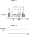
- Fig. 8 , Fig. 11A, and Fig. 11B are diagrams used to explain conventional arc-welding methods for welding galvanized steel sheets, for example.
- Fig. 8 shows a section of a bead when galvanized steel sheets are welded by a consumable electrode type arc-welding method, which is a typical welding method.
- the boiling point of zinc in galvanization 27 on the surfaces of objects to be welded 25 is 907°C, which is lower than the melting point of iron, 1536°C.
- zinc vaporizes and this zinc vapor attempts to pass through a molten pool and diffuse to the outside.
- the zinc vapor cannot be released to the outside of the molten pool sufficiently and remains, as porosity 28, inside or on the surface of welding bead 26.
- Porosity 28 remaining in welding bead 26 forms a blow hole.
- Porosity 28 remaining opened to the surface of welding bead 26 forms a pit.
- blow holes and pits affect the strength of welding. For this reason, in the automobile industry, where a large number of galvanized steel sheets are used, blow holes and pits need to be suppressed, and especially the amount of pits is predetermined and controlled in many cases.
- Fig. 11A and Fig. 11B show waveforms of a welding current and a wire-feeding speed when pulse welding is performed with Ar, or a mixture gas containing Ar and carbon dioxide gas in an amount of 25% or less added thereto.
- Fig. 11A shows a waveform of the welding current;
- Fig 11B shows a waveform of the wire-feeding speed.
- the waveform of the welding current includes first period TL and second period TH.
- the sum of first period TL and second period TH is waviness period TW.
- Waviness period TW is a period in which a number of cycles are repeated in one second.
- the current waveform pattern or the wire-feeding speed is changed at frequencies of 10 to 50 Hz in waviness period TW.
- First period TL is a period of a current waveform in which first average arc force FL acts on the molten pool.
- Second period TH is a period of a current waveform in which second average arc force FH, which is larger than first average arc force FL, acts on the molten pool.
- the arc force acts as the force that pushes down the molten pool.
- changing first average arc force FL and second average arc force FH makes the molten pool in a waving state.
- any porosity 28 generated from the galvanized layer in the molten pool reaches the surface of the molten pool because of the flow of the molten pool and the buoyancy of porosity 28, and is released to the outside of the molten pool.
- the thickness of the object is 2.0 mm or greater, the necessary amount of penetration is increased. This increases the thickness of the molten pool, and hinders release of zinc vapor.
- a galvanized steel sheet having a zinc coating weight greater than 45g/m 2 is welded, the amount of generation of zinc vapor increases. Such zinc vapor is not released and remains in welding bead 26. This increases the amount of generation of porosities 28 (blow holes and pits).
- the zinc vapor floats in the molten pool and is released from the surface of the molten pool.
- the molten metal gushed out at the release of zinc vapor is scattered as spatters, or short-circuits with the welding wire and is scattered by the electric energy as spatters.
- an abnormally large amount of spatters are generated.
- the arc-welding method of the present invention is an arc-welding method in welding by repeating a short circuit and an arc.
- the welding current is reduced from a first current value at the detection of the sign to a second current value, which is lower than the first current value.
- a pulse current having a peak value higher than the first current value is supplied at a plurality of times in the arc period.
- the lower limit of the pulse current supplied at the plurality of times in the arc period is lower than the first current value.
- the lower limit of the pulse current supplied at the plurality of times in the arc period is lower than the second current value.
- a wire may be fed at a wire-feeding speed of repeating a forward feed and a reverse feed.
- the forward feed and the reverse feed at the wire-feeding speed may be periodically repeated in a predetermined cycle at a predetermined amplitude.
- the forward feed and the reverse feed at the wire-feeding speed may not be repeated periodically.
- the reverse feed is performed.
- the forward feed is performed.
- An arc-welding apparatus of the present invention is an arc-welding apparatus for welding by repeating a short circuit and an arc, and includes a primary rectifier, a switching part, a transformer, a secondary rectifier, a driver, a welding voltage detector, a short-circuit/arc detector, a short-circuit controller, and an arc controller.
- the primary rectifier rectifies the input electric power
- the switching part converts the output from the primary rectifier into an alternating current.
- the transformer transforms the output from the switching part.
- the secondary rectifier rectifies the output from the transformer.
- the driver controls the switching part, and the welding voltage detector detects a welding voltage.
- the short-circuit/arc detector has a function of determining whether the welding state is a short-circuit state or an arc state in response to the output from the welding voltage detector, and a function of detecting the sign of changing from the short-circuit state to the arc state in response to the output from the welding voltage detector.
- the short-circuit controller controls the welding output in the short-circuit state.
- the arc controller controls the welding output in the arc state.
- the arc-welding apparatus of the present invention may further include a wire-feeding speed controller for controlling feeding of a welding wire, and feeds the welding wire at a wire-feeding speed of repeating a forward feed and a reverse feed.
- the molten pool is pushed so that the overlapped parts of surface-treated members are exposed when the members are welded with a welding wire. This allows the gas generated from the members to escape from the exposed root part, thereby suppressing generation of porosities, such as blow holes, and spatters.
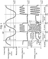
- Fig. 1 is a waveform chart showing a temporal change in a wire-feeding speed, a welding voltage, and a welding current in consumable electrode type arc-welding for alternately repeating a short-circuit state and an arc state.
- wire feeding in reference to predetermined wire-feeding speed Wf1, wire feeding is controlled at a predetermined frequency at a predetermined amplitude.
- wire feeding is controlled so that a forward feed and a reverse feed are periodically repeated. That is, regardless of whether the welding state is a short-circuit state or an arc state, a forward feed and a reverse feed are periodically repeated in reference to the basic waveform in the form of a sine wave.
- a forward feed and a reverse feed are periodically repeated in reference to the basic waveform in the form of a sine wave.
- a short circuit occurs around time point P1.
- an arc occurs around time point P2.
- time point P3 i.e. at the peak of the forward feed after time point P2, the next short circuit occurs.
- the period from time point P1 to time point P3 is set as one cycle of control, and this cycle is repeated for welding.
- wire-feeding speed Wf is in the forward direction
- the short circuit is promoted.
- the wire-feeding speed Wf is in the reverse direction
- opening is promoted. In this manner, occurrence of a short-circuit state and an arc state depends basically on wire-feeding control of periodically repeating a forward feed and a reverse feed at the wire-feeding speed.
- Time point P1 shows the time point at which a short circuit starts, and short-circuit initial current SA is output from time point P1 for a predetermined time period.
- the short-circuit current is increased with short-circuit current increasing gradient di/dt in the first step (the amount of current increase per unit time).
- the short-circuit current is increased with short-circuit current increasing gradient di/dt in the second step (the amount of current increase per unit time), which is gentler than increasing gradient di/dt in the first step (the amount of current increase per unit time).
- constriction current NA a second current value
- current IA a first current value
- Time point P2 shows the time point at which separation of the droplet constriction opens the short circuit, the short circuit state ends, and an arc state starts.
- a welding current at peak current PP is output for peak current period TP immediately after the opening of the short circuit, i.e. immediately after occurrence of an arc.
- the welding current changes from peak current PP to base current PB, and base current PB is output for base current period TB.
- the change between peak current PP and base current PB is controlled with predetermined current changing gradient di/dt (the amount of current change per unit time), or a rising time and a falling time, so that a predetermined number of pulses are output at a predetermined pulse frequency (pulse cycle PF).
- Fig. 1 shows an example where the number of pulses is four. Peak current PP is larger than current IA at the detection of the constriction, and constriction current NA. Base current PB is smaller than current IA at the detection of the constriction, and constriction current NA.
- Time point P3 shows the time point at which a short circuit occurs next to time point P1.
- the state is the same as that at time point P1.
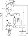
- FIG. 2 is a diagram showing a schematic configuration of an arc-welding apparatus in accordance with the exemplary embodiment.
- the arc-welding apparatus includes welding power supply 15, manipulator 18, robot controller 16, and torch 21.
- Robot controller 16 controls manipulator 18.
- Torch 21 is attached to manipulator 18 and includes feed-roller 22 and welding tip 23.
- welding power supply 15 includes primary rectifier 2, switching part 3, transformer 4, secondary rectifier 5, DCL 6, driver 7, welding voltage detector 8, welding current detector 9, short-circuit/arc detector 10, short-circuit controller 11, arc controller 12, pulse waveform controller 13, and wire-feeding speed controller 14.
- Primary rectifier 2 rectifies the electric power input from input power supply 1.
- Switching part 3 converts the output from primary rectifier 2 into an alternating current.
- Transformer 4 steps down the output from switching part 3.
- Driver 7 controls switching part 3.
- Welding voltage detector 8 is connected between the output terminals of welding power supply 15, and detects a welding voltage.
- Welding current detector 9 detects the welding output current.
- short-circuit/arc detector 10 determines a short-circuit state in which welding wire 20 short-circuits with objects to be welded 25 or an arc state in which an arc occurs between welding wire 20 and objects to be welded 25.
- short-circuit controller 11 controls the short-circuit current in the short-circuit period.
- arc controller 12 controls the arc voltage in the arc period.
- Pulse waveform controller 13 is disposed in arc controller 12.
- Wire-feeding speed controller 14 controls the feeding of welding wire 20.
- Short-circuit/arc detector 10 also has a function of detecting a constriction, which is a sign of the change from a short-circuit state to an arc state, in response to the output from welding voltage detector 8.
- the output from welding power supply 15 is applied between objects to be welded 25 and welding wire 20 that is drawn from wire storage 19 and passes through welding tip 23. This generates arc 24 between welding wire 20 and objects to be welded 25.
- Robot controller 16 includes set current setting part 17 for setting a set current, i.e. an average welding current.
- the output from set current setting part 17 is input into wire-feeing speed controller 14.
- short-circuit/arc detector 10 determines a short-circuit state or an arc state.
- Short-circuit/arc detector 10 may determine a short-circuit state or an arc state, in response to both of a signal from welding voltage detector 8 and a signal from welding current detector 9.
- short-circuit controller 11 controls the welding output in the short-circuit period by controlling driver 7.
- arc controller 12 controls the welding output in the arc period by controlling driver 7.
- Pulse waveform controller 13 disposed in arc controller 12 determines the pulse waveform suitable for each current set in set current setting part 17.
- Pulse waveform controller 13 determines the pulse waveform, pulse frequency, and the number of pulses suitable for each current set in set current setting part 17. Pulse waveform controller 13 includes a table or a relational expression correlating the set current, pulse waveform, pulse frequency, and the number of pulses with each other. Pulse waveform controller 13 determines that a predetermined number of pulse waveforms are output at a predetermined frequency based on the set current.
- Fig. 3 is a diagram illustrating a welding state in accordance with the exemplary embodiment.
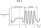
- Fig. 4 is a diagram showing a waveform of a welding current in accordance with the exemplary embodiment.
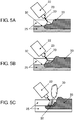
- Fig. 5A is a sectional view of a short-circuit state in accordance with the exemplary embodiment.
- Fig. 5B is a sectional view in a state where a first pulse after opening of a short circuit is given in accordance with the exemplary embodiment.
- Fig. 5C is a sectional view in a state where a fourth pulse is given in accordance with the exemplary embodiment.
- Fig. 6 is a diagram showing a section of a welding part in accordance with the exemplary embodiment.
- FIG. 7 is a diagram showing a section of a welding part in accordance with the exemplary embodiment.
- Fig. 6 is a section taken on line B-B in the welding state shown in Fig. 3 ;
- Fig. 7 is a section taken on line C-C in the welding state shown in Fig. 3 .
- Fig. 5A-Fig. 5C show sections taken on line A-A in the welding state shown in Fig. 3 and correspond to time points a-c in the welding current waveform shown in Fig. 4 .
- Fig. 5A is a sectional view at time point a shown in Fig. 4 , that is, a sectional view in a short-circuit state.
- Fig. 5B is a sectional view at time point b shown in Fig. 4 , that is, a sectional view when a first pulse current is given in the arc period after the opening of the short circuit.
- Fig. 5C is a sectional view at time point c shown in Fig. 4 , that is, a sectional view when a fourth pulse current is given in the arc period after the opening of the short circuit.
- One pulse current is capable of pushing out molten metal 33 of the molten pool in root part 32 of objects to be welded 25.
- the suitable number of pulse currents varies with the coating weight of galvanization 27. As the coating weight increases, the exposure time of root part 32 of objects to be welded 25 needs to be increased so that zinc vapor 30 is released easily. For this purpose, it is preferable to increase the number of pulse currents in the suitable period. However, an excessive number of pulse currents reduce the number of short circuits. Thus, preferably, the upper limit is seven pulse currents with which approximately 30 short circuits occur.
- molten metal 33 of the molten pool may be pushed by the arc force of arc 24 so as to have the following thickness.
- volume-expanded zinc vapor 30 generated from the top plate and the bottom plate of objects to be welded 25 can break molten portions 29 and molten metal 33 of the molten pool covering root part 32 of objects to be welded 25 and pass therethrough.
- Root part 32 can be exposed by pushing molten metal 33 of the molten pool in the state where the arc length immediately after the opening of the short circuit is short (approximately 1 mm to 2 mm). In simple pulse welding, even a short arc length ranges from approximately 4 mm to 5 mm. Such a long arc length cannot exert the arc force sufficient to push molten metal 33 of the molten pool.
- Root part 32 of objects to be welded 25 can be exposed by setting peak current PP and base current PB of the pulse waveform and the pulse frequency (pulse cycle PF) of Fig. 1 to the following parameters.
- each of peak current period TP and base current period TB i.e. the time period during which molten metal 33 of the molten pool is pushed, is set to 100 ⁇ s to 500 ⁇ s.
- the suitable pulse frequency ranges from 300 Hz to 1500 Hz, that is, suitable pulse cycle PF ranges from approximately 3333 ⁇ s to 666 ⁇ s. It is not necessary that peak current period TP and base current period TB have the same period of time. Gradient di/dt rising from base current PB to peak current PP and gradient di/dt falling from peak current PP to base current PB are determined based on the above parameters.
- the control of the exemplary embodiment can suppress generation of porosities 28.
- outputting a plurality of pulses is unnecessary in the steady welding period.
- outputting a plurality of pulses is effective in the arc start period not only for MAG welding but also for CO 2 welding.
- the exemplary embodiment shows an example where peak current PP and base current PB of the pulse waveform, a pulse frequency (pulse cycle PF), and the number of pulse waveforms are determined based on the set current.
- the set current is proportional to the wire-feeding speed and wire-feeding amount.
- the similar advantage can be obtained by determining the parameters related to pulse waveforms based on the wire-feeding speed and the wire-feeding amount instead of the set current.
- the similar advantage can be obtained by the feeding control where a reverse feed is made when the welding state is a short-circuit state and a forward feed is made when the welding state is an arc state.
- the feeding control is periodical, but it is not necessary to be periodical.
- Fig. 1 shows the following example.
- a constriction of a droplet that is formed between the molten pool formed on objects to be welded 25 and the tip of welding wire 20 is detected.
- the welding current is instantaneously changed to constriction current NA, which is lower than current IA at the detection of the constriction.
- a plurality of pulse currents are supplied.
- opening of the short circuit may be detected instead of detection of a constriction and the reduction of current upon the constriction detection as shown in Fig. 1 .
- a pulse current having a peak value higher than the current value at the opening of the short circuit is supplied at a plurality of times.
- lower limit of the pulse current supplied at a plurality of times in the arc period is set lower than the current value at the opening of the short circuit. This is because a large difference between the upper limit and the lower limit of the pulse current can relatively vary the arc force and enhance the effect of pushing molten metal 33 of the molten pool. The smaller lower limit of the pulse current can reduce the energy exerted on welding wire 20, thereby suppressing the separation of the droplet.
- the present invention when surface-treated members, such as galvanized steel sheets, are welded with a welding wire, gas generated from the members is released from the exposed part by pushing the molten pool so as to expose the overlapped parts of the members. This can considerably suppress generation of porosities, such as blow holes, and generation of spatters.
- the present invention is industrially useful as an arc-welding method and an arc-welding apparatus used to weld surface-treated members, such as galvanized steel sheets, which generates gas during welding.
Landscapes
- Engineering & Computer Science (AREA)
- Physics & Mathematics (AREA)
- Plasma & Fusion (AREA)
- Mechanical Engineering (AREA)
- Arc Welding Control (AREA)
Claims (6)
- Procédé de soudage à l'arc par soudage par répétition d'un court-circuit et d'un arc,
le procédé de soudage à l'arc comprenant :lorsqu'un signe d'ouverture du court-circuit est détecté, la réduction d'un courant de soudage d'une première valeur de courant pendant la détection du signe à une deuxième valeur de courant, qui est inférieure à la première valeur de courant ; etlorsque l'ouverture du court-circuit est détectée, la fourniture d'un courant d'impulsion présentant une valeur de crête supérieure à la première valeur de courant pendant une pluralité de fois au cours d'une période d'arc,caractérisé en ce queune limite inférieure du courant d'impulsion fourni pendant une pluralité de fois au cours de la période d'arc est inférieure à la deuxième valeur de courant. - Procédé de soudage à l'arc selon la revendication 1, dans lequel un fil est apporté à une vitesse d'apport de fil consistant à répéter un apport avant et un apport inverse.
- Procédé de soudage à l'arc selon la revendication 2, dans lequel l'apport avant et l'apport inverse à la vitesse d'apport de fil sont répétés périodiquement au cours d'un cycle prédéterminé à une amplitude prédéterminée.
- Procédé de soudage à l'arc selon la revendication 2, dans lequel
l'apport avant et l'apport inverse à la vitesse d'apport de fil ne sont pas répétés périodiquement,
lorsqu'un état de soudage d'un état de court-circuit est détecté, l'apport inverse est effectué, et
lorsqu'un état de soudage d'un état d'arc est détecté, l'apport avant est effectué. - Appareil de soudage à l'arc pour un soudage par répétition d'un court-circuit et d'un arc, l'appareil de soudage à l'arc comprenant :un redresseur primaire (2) destiné à redresser le courant électrique entré ;une partie de commutation (3) destinée à convertir la sortie provenant du redresseur primaire (2) en un courant alternatif ;un transformateur (4) destiné à transformer la sortie provenant de la partie de commutation (3) ;un redresseur secondaire (5) destiné à redresser la sortie provenant du transformateur (4) ;un pilote (7) destiné à commander la partie de commutation (3) ;un détecteur de tension de soudage (8) destiné à détecter une tension de soudage ;un détecteur de court-circuit/d'arc (10) présentant une fonction de détermination si un état de soudage est un état de court-circuit ou un état d'arc en réponse à une sortie provenant du détecteur de tension de soudage (8), et une fonction de détection d'un signe de passage de l'état de court-circuit à l'état d'arc en réponse à la sortie provenant du détecteur de tension de soudage (8) ;un dispositif de commande de court-circuit (11) destiné à commander la sortie de soudage dans l'état de court-circuit ; etun dispositif de commande d'arc (12) destiné à commander la sortie de soudage dans l'état d'arc,dans lequel, lorsqu'un signe d'ouverture du court-circuit est détecté, un courant de soudage est réduit d'une première valeur de courant pendant la détection du signe à une deuxième valeur de courant qui est inférieure à la première valeur de courant,lorsque l'ouverture du court-circuit est détectée, une impulsion de courant présentant une valeur de crête supérieure à la première valeur de courant est fournie pendant une pluralité de fois au cours d'une période d'arc, etcaractérisé en ce queune limite inférieure du courant d'impulsion apporté pendant la pluralité de fois au cours de la période d'arc est inférieure à la deuxième valeur de courant.
- Appareil de soudage à l'arc selon la revendication 5, comprenant en outre un dispositif de commande de vitesse d'apport de fil (14) destiné à commander l'apport d'un fil de soudage, dans lequel le fil de soudage est apporté à une vitesse d'apport de fil consistant à répéter un apport avant et un apport inverse.
Applications Claiming Priority (2)
| Application Number | Priority Date | Filing Date | Title |
|---|---|---|---|
| JP2012136604 | 2012-06-18 | ||
| PCT/JP2013/001550 WO2013190746A1 (fr) | 2012-06-18 | 2013-03-11 | Procédé de soudage à l'arc et appareil de soudage à l'arc |
Publications (3)
| Publication Number | Publication Date |
|---|---|
| EP2862661A1 EP2862661A1 (fr) | 2015-04-22 |
| EP2862661A4 EP2862661A4 (fr) | 2016-01-27 |
| EP2862661B1 true EP2862661B1 (fr) | 2017-05-03 |
Family
ID=49768361
Family Applications (1)
| Application Number | Title | Priority Date | Filing Date |
|---|---|---|---|
| EP13806261.7A Active EP2862661B1 (fr) | 2012-06-18 | 2013-03-11 | Procédé de soudage à l'arc et appareil de soudage à l'arc |
Country Status (6)
| Country | Link |
|---|---|
| US (2) | US9776273B2 (fr) |
| EP (1) | EP2862661B1 (fr) |
| JP (1) | JP6089231B2 (fr) |
| KR (1) | KR102056043B1 (fr) |
| CN (1) | CN104364043B (fr) |
| WO (1) | WO2013190746A1 (fr) |
Families Citing this family (34)
| Publication number | Priority date | Publication date | Assignee | Title |
|---|---|---|---|---|
| EP3117944B1 (fr) * | 2014-03-10 | 2019-01-02 | Daihen Corporation | Procédé de commande de soudage à l'arc |
| US10456852B2 (en) * | 2014-04-22 | 2019-10-29 | Daihen Corporation | Arc welding control method |
| EP3147064B1 (fr) * | 2014-05-19 | 2020-12-09 | Daihen Corporation | Procédé de commande de soudage à l'arc |
| JP6596669B2 (ja) * | 2014-11-11 | 2019-10-30 | パナソニックIpマネジメント株式会社 | アーク溶接の制御方法 |
| JP6114785B2 (ja) * | 2015-05-29 | 2017-04-12 | 日新製鋼株式会社 | 溶接部外観と溶接強度に優れた溶融Zn系めっき鋼板のアーク溶接方法、および溶接部材の製造方法 |
| JP6518160B2 (ja) * | 2015-07-27 | 2019-05-22 | 株式会社神戸製鋼所 | 亜鉛めっき鋼板の溶接方法 |
| JP6754952B2 (ja) * | 2015-09-03 | 2020-09-16 | パナソニックIpマネジメント株式会社 | アーク溶接方法およびアーク溶接装置 |
| US11691212B2 (en) | 2015-09-30 | 2023-07-04 | Daihen Corporation | Arc welding apparatus and arc welding method |
| CN105710504B (zh) * | 2016-03-14 | 2017-10-31 | 唐山松下产业机器有限公司 | 一种脉冲焊接装置及其主焊接过程控制方法 |
| CN108883486B (zh) | 2016-03-29 | 2020-07-14 | 松下知识产权经营株式会社 | 电弧焊接控制方法 |
| DE102017208924A1 (de) * | 2016-07-19 | 2018-01-25 | Siemens Energy, Inc. | Prozess und Vorrichtung zum Schweissen eines Werkstücks mit wärmeempfindlichem Material |
| US11161191B2 (en) | 2016-07-19 | 2021-11-02 | Siemens Energy, Inc. | Process and apparatus for welding workpiece having heat sensitive material |
| JP6948528B2 (ja) * | 2016-10-11 | 2021-10-13 | パナソニックIpマネジメント株式会社 | アーク溶接方法およびアーク溶接装置 |
| JP6385411B2 (ja) | 2016-10-28 | 2018-09-05 | 日新製鋼株式会社 | 溶接部材およびその製造方法 |
| WO2019245063A1 (fr) * | 2018-06-18 | 2019-12-26 | 주식회사 포스코 | Élément de soudure en tôle d'acier plaquée ayant une excellente résistance à la porosité et une excellente propriété de fatigue de zone de soudure, et son procédé de fabrication |
| US11815127B2 (en) | 2016-12-23 | 2023-11-14 | Posco Co., Ltd | Welded member for plated steel plate excellent in weld zone porosity resistance and fatigue properties and method for manufacturing the same |
| WO2018131345A1 (fr) * | 2017-01-16 | 2018-07-19 | 株式会社ダイヘン | Procédé de commande de démarrage d'arc pour le soudage à l'arc par alimentation avant et arrière |
| US10500671B2 (en) * | 2017-04-06 | 2019-12-10 | Lincoln Global, Inc. | System and method for arc welding and wire manipulation control |
| JP7407398B2 (ja) * | 2018-04-18 | 2024-01-04 | パナソニックIpマネジメント株式会社 | アーク溶接の制御方法 |
| EP3865240B1 (fr) * | 2018-10-12 | 2024-01-03 | Panasonic Intellectual Property Management Co., Ltd. | Procédé de commande de soudage à l'arc |
| JP2020131200A (ja) * | 2019-02-13 | 2020-08-31 | 株式会社ダイヘン | アーク溶接方法 |
| KR102135663B1 (ko) * | 2019-02-15 | 2020-07-21 | 현대종합금속 주식회사 | Co2 100% 가스를 이용한 플럭스-코어-와이어 용 펄스용접 파형제어방법 |
| JP7267770B2 (ja) * | 2019-02-25 | 2023-05-02 | 株式会社神戸製鋼所 | めっき鋼板の接合方法及び接合構造体 |
| JP7198557B2 (ja) * | 2019-03-20 | 2023-01-04 | 株式会社ダイヘン | アーク溶接方法 |
| US11958141B2 (en) * | 2019-10-31 | 2024-04-16 | Illinois Tool Works Inc. | Systems and methods to provide welding-type arc starting and stabilization with reduced open circuit voltage |
| US12390873B2 (en) | 2019-11-01 | 2025-08-19 | Illinois Tool Works Inc. | Systems and methods to control welding-type power supplies using AC waveforms and/or DC pulse waveforms |
| US20210129252A1 (en) * | 2019-11-01 | 2021-05-06 | Illinois Tool Works Inc. | Systems and methods to control welding-type power supplies using ac waveforms and/or dc pulse waveforms |
| CN111014888A (zh) * | 2019-12-27 | 2020-04-17 | 浙江威帕科智能装备有限公司 | 一种电弧焊接方法及电弧焊接装置 |
| US12521810B2 (en) * | 2021-04-13 | 2026-01-13 | Esab Ab | Overvoltage protection for current braking switch |
| US12521811B2 (en) * | 2021-11-10 | 2026-01-13 | Lincoln Global, Inc. | Welding or additive manufacturing system with discontinuous electrode feeding |
| CN118401329A (zh) * | 2021-11-29 | 2024-07-26 | 松下知识产权经营株式会社 | 电弧焊接方法和电弧焊接装置 |
| CN114367721A (zh) * | 2021-12-27 | 2022-04-19 | 唐山松下产业机器有限公司 | 运用于脉冲电弧焊机的脉冲控制方法及装置、存储介质 |
| CN114289830B (zh) * | 2021-12-30 | 2023-10-20 | 唐山松下产业机器有限公司 | 焊缝成型补偿方法及装置、存储介质及电子设备 |
| CN117102630B (zh) * | 2023-10-24 | 2024-02-27 | 广东美的制冷设备有限公司 | 电弧焊焊接质量监测方法、装置、电子设备和存储介质 |
Family Cites Families (27)
| Publication number | Priority date | Publication date | Assignee | Title |
|---|---|---|---|---|
| JPS60223662A (ja) * | 1984-04-20 | 1985-11-08 | Hitachi Seiko Ltd | ア−ク溶接法 |
| JPS60223661A (ja) * | 1984-04-20 | 1985-11-08 | Hitachi Seiko Ltd | ア−ク溶接法 |
| US4665299A (en) * | 1984-09-28 | 1987-05-12 | Mitsubishi Denki Kabushiki Kaisha | Arc welding power source with response delay compensating control |
| JPH01299769A (ja) * | 1988-05-24 | 1989-12-04 | Sansha Electric Mfg Co Ltd | ガスシールドアーク溶接用電源の出力制御方法 |
| US5281791A (en) * | 1989-02-28 | 1994-01-25 | Mitsubishi Denki K.K. | Pulsed arc welding apparatus |
| JPH038579A (ja) | 1989-06-05 | 1991-01-16 | Mitsubishi Electric Corp | パルス溶接装置 |
| WO1991001842A1 (fr) * | 1989-08-02 | 1991-02-21 | Mitsubishi Denki Kabushiki Kaisha | Appareil de soudage par impulsions |
| KR100219813B1 (ko) * | 1990-04-17 | 1999-09-01 | 니시마쓰 다이조 | Mag 아아크 용접 방법 및 용접장치 |
| US5473139A (en) | 1993-01-18 | 1995-12-05 | Toyota Jidosha Kabushiki Kaisha | Pulsed arc welding apparatus having a consumable electrode wire |
| JP3146741B2 (ja) | 1993-04-06 | 2001-03-19 | トヨタ自動車株式会社 | 鋼材のアーク溶接方法 |
| JP3188821B2 (ja) * | 1995-05-15 | 2001-07-16 | 株式会社神戸製鋼所 | 亜鉛めっき鋼板のマグパルスアーク溶接方法 |
| JP3284930B2 (ja) * | 1997-07-09 | 2002-05-27 | 株式会社日立製作所 | 高周波パルスアーク溶接法とその装置及び用途 |
| JP3003673B2 (ja) * | 1998-06-17 | 2000-01-31 | 松下電器産業株式会社 | 消耗電極式パルスアーク溶接方法 |
| US6501049B2 (en) * | 2001-01-23 | 2002-12-31 | Lincoln Global, Inc. | Short circuit arc welder and method of controlling same |
| JP3951931B2 (ja) * | 2003-02-10 | 2007-08-01 | 松下電器産業株式会社 | 溶接制御方法及び消耗電極式パルスアーク溶接装置 |
| CN102009245A (zh) * | 2003-10-23 | 2011-04-13 | 弗罗纽斯国际有限公司 | 控制焊接工艺的方法以及实施焊接工艺的焊接设备 |
| JP4459768B2 (ja) * | 2004-09-22 | 2010-04-28 | 株式会社ダイヘン | 交流パルスアーク溶接の溶接電流制御方法 |
| JP4760053B2 (ja) * | 2005-02-28 | 2011-08-31 | パナソニック株式会社 | アーク溶接装置の制御方法およびアーク溶接装置 |
| JP3844004B1 (ja) | 2005-05-31 | 2006-11-08 | 松下電器産業株式会社 | パルスアーク溶接制御方法及びパルスアーク溶接装置 |
| JP4498263B2 (ja) * | 2005-11-08 | 2010-07-07 | 株式会社神戸製鋼所 | パルスアーク溶接方法 |
| WO2008105116A1 (fr) * | 2007-02-28 | 2008-09-04 | Panasonic Corporation | Procédé de commande de sortie de soudage et dispositif de soudage à l'arc |
| US8373093B2 (en) * | 2008-06-27 | 2013-02-12 | Lincoln Global, Inc. | Method and system to increase heat input to a weld during a short-circuit arc welding process |
| US8723080B2 (en) | 2009-07-10 | 2014-05-13 | Panasonic Corporation | Arc welding control method and arc welding apparatus |
| US20110287764A1 (en) | 2010-05-21 | 2011-11-24 | Interop Technologies | Home location register query reduction apparatus and methods |
| JP5626866B2 (ja) * | 2010-08-20 | 2014-11-19 | 株式会社ダイヘン | アーク溶接方法およびアーク溶接システム |
| EP2505294B1 (fr) * | 2010-10-07 | 2016-08-31 | Panasonic Intellectual Property Management Co., Ltd. | Procédé de soudage à l'arc et dispositif de soudage à l'arc |
| JP2012081501A (ja) * | 2010-10-13 | 2012-04-26 | Panasonic Corp | アーク溶接制御方法およびアーク溶接装置 |
-
2013
- 2013-03-11 EP EP13806261.7A patent/EP2862661B1/fr active Active
- 2013-03-11 WO PCT/JP2013/001550 patent/WO2013190746A1/fr not_active Ceased
- 2013-03-11 KR KR1020147032574A patent/KR102056043B1/ko active Active
- 2013-03-11 CN CN201380032007.5A patent/CN104364043B/zh active Active
- 2013-03-11 JP JP2014520866A patent/JP6089231B2/ja active Active
-
2014
- 2014-10-24 US US14/522,909 patent/US9776273B2/en active Active
-
2017
- 2017-08-28 US US15/687,850 patent/US10654121B2/en active Active
Also Published As
| Publication number | Publication date |
|---|---|
| US10654121B2 (en) | 2020-05-19 |
| KR20150024312A (ko) | 2015-03-06 |
| US20150041449A1 (en) | 2015-02-12 |
| EP2862661A1 (fr) | 2015-04-22 |
| US9776273B2 (en) | 2017-10-03 |
| EP2862661A4 (fr) | 2016-01-27 |
| KR102056043B1 (ko) | 2019-12-16 |
| WO2013190746A1 (fr) | 2013-12-27 |
| CN104364043A (zh) | 2015-02-18 |
| JP6089231B2 (ja) | 2017-03-08 |
| US20170355035A1 (en) | 2017-12-14 |
| CN104364043B (zh) | 2017-06-16 |
| JPWO2013190746A1 (ja) | 2016-02-08 |
Similar Documents
| Publication | Publication Date | Title |
|---|---|---|
| US10654121B2 (en) | Arc-welding method and arc-welding apparatus | |
| US8723080B2 (en) | Arc welding control method and arc welding apparatus | |
| EP2918365B1 (fr) | Soudeuse à arc électrique et procédé de commande de soudage à l'arc | |
| EP2455177B1 (fr) | Procédé de commande de soudage à l'arc | |
| JP7090227B2 (ja) | アーク溶接装置およびアーク溶接制御方法 | |
| JP6778857B2 (ja) | アーク溶接制御方法 | |
| EP3858530A1 (fr) | Source d'énergie de soudage, système de soudage, procédé de commande de source d'énergie de soudage, et programme | |
| JPWO2012046411A1 (ja) | アーク溶接方法およびアーク溶接装置 | |
| JP6145694B2 (ja) | アーク溶接制御方法およびアーク溶接装置 | |
| JP2014226709A (ja) | アーク溶接制御方法およびアーク溶接装置 | |
| JP6268360B2 (ja) | アーク溶接制御方法およびアーク溶接装置 | |
| EP3960351A1 (fr) | Procédé de commande de soudage à l'arc et dispositif de soudage à l'arc | |
| JP2014073521A (ja) | アーク溶接制御方法およびアーク溶接装置 | |
| JP7582923B2 (ja) | 溶接制御方法、溶接制御装置、溶接電源、溶接システム、プログラム、溶接方法及び付加製造方法 | |
| JP6948528B2 (ja) | アーク溶接方法およびアーク溶接装置 | |
| JP6019380B2 (ja) | アーク溶接制御方法およびアーク溶接装置 | |
| JP2016026880A (ja) | パルスアーク溶接の出力制御方法 |
Legal Events
| Date | Code | Title | Description |
|---|---|---|---|
| PUAI | Public reference made under article 153(3) epc to a published international application that has entered the european phase |
Free format text: ORIGINAL CODE: 0009012 |
|
| 17P | Request for examination filed |
Effective date: 20141001 |
|
| AK | Designated contracting states |
Kind code of ref document: A1 Designated state(s): AL AT BE BG CH CY CZ DE DK EE ES FI FR GB GR HR HU IE IS IT LI LT LU LV MC MK MT NL NO PL PT RO RS SE SI SK SM TR |
|
| AX | Request for extension of the european patent |
Extension state: BA ME |
|
| DAX | Request for extension of the european patent (deleted) | ||
| RA4 | Supplementary search report drawn up and despatched (corrected) |
Effective date: 20160104 |
|
| RIC1 | Information provided on ipc code assigned before grant |
Ipc: B23K 9/12 20060101ALI20151218BHEP Ipc: B23K 9/09 20060101ALI20151218BHEP Ipc: B23K 9/173 20060101ALI20151218BHEP Ipc: B23K 9/073 20060101AFI20151218BHEP Ipc: B23K 9/095 20060101ALI20151218BHEP |
|
| GRAP | Despatch of communication of intention to grant a patent |
Free format text: ORIGINAL CODE: EPIDOSNIGR1 |
|
| RIC1 | Information provided on ipc code assigned before grant |
Ipc: B23K 9/12 20060101ALI20161014BHEP Ipc: B23K 9/173 20060101ALI20161014BHEP Ipc: B23K 9/073 20060101AFI20161014BHEP Ipc: B23K 9/09 20060101ALI20161014BHEP Ipc: B23K 9/095 20060101ALI20161014BHEP |
|
| INTG | Intention to grant announced |
Effective date: 20161103 |
|
| GRAS | Grant fee paid |
Free format text: ORIGINAL CODE: EPIDOSNIGR3 |
|
| GRAA | (expected) grant |
Free format text: ORIGINAL CODE: 0009210 |
|
| AK | Designated contracting states |
Kind code of ref document: B1 Designated state(s): AL AT BE BG CH CY CZ DE DK EE ES FI FR GB GR HR HU IE IS IT LI LT LU LV MC MK MT NL NO PL PT RO RS SE SI SK SM TR |
|
| REG | Reference to a national code |
Ref country code: GB Ref legal event code: FG4D |
|
| REG | Reference to a national code |
Ref country code: AT Ref legal event code: REF Ref document number: 889441 Country of ref document: AT Kind code of ref document: T Effective date: 20170515 Ref country code: CH Ref legal event code: EP |
|
| REG | Reference to a national code |
Ref country code: IE Ref legal event code: FG4D |
|
| REG | Reference to a national code |
Ref country code: DE Ref legal event code: R096 Ref document number: 602013020751 Country of ref document: DE |
|
| REG | Reference to a national code |
Ref country code: NL Ref legal event code: MP Effective date: 20170503 |
|
| REG | Reference to a national code |
Ref country code: AT Ref legal event code: MK05 Ref document number: 889441 Country of ref document: AT Kind code of ref document: T Effective date: 20170503 |
|
| REG | Reference to a national code |
Ref country code: LT Ref legal event code: MG4D |
|
| PG25 | Lapsed in a contracting state [announced via postgrant information from national office to epo] |
Ref country code: AT Free format text: LAPSE BECAUSE OF FAILURE TO SUBMIT A TRANSLATION OF THE DESCRIPTION OR TO PAY THE FEE WITHIN THE PRESCRIBED TIME-LIMIT Effective date: 20170503 Ref country code: GR Free format text: LAPSE BECAUSE OF FAILURE TO SUBMIT A TRANSLATION OF THE DESCRIPTION OR TO PAY THE FEE WITHIN THE PRESCRIBED TIME-LIMIT Effective date: 20170804 Ref country code: HR Free format text: LAPSE BECAUSE OF FAILURE TO SUBMIT A TRANSLATION OF THE DESCRIPTION OR TO PAY THE FEE WITHIN THE PRESCRIBED TIME-LIMIT Effective date: 20170503 Ref country code: LT Free format text: LAPSE BECAUSE OF FAILURE TO SUBMIT A TRANSLATION OF THE DESCRIPTION OR TO PAY THE FEE WITHIN THE PRESCRIBED TIME-LIMIT Effective date: 20170503 Ref country code: FI Free format text: LAPSE BECAUSE OF FAILURE TO SUBMIT A TRANSLATION OF THE DESCRIPTION OR TO PAY THE FEE WITHIN THE PRESCRIBED TIME-LIMIT Effective date: 20170503 Ref country code: NO Free format text: LAPSE BECAUSE OF FAILURE TO SUBMIT A TRANSLATION OF THE DESCRIPTION OR TO PAY THE FEE WITHIN THE PRESCRIBED TIME-LIMIT Effective date: 20170803 Ref country code: ES Free format text: LAPSE BECAUSE OF FAILURE TO SUBMIT A TRANSLATION OF THE DESCRIPTION OR TO PAY THE FEE WITHIN THE PRESCRIBED TIME-LIMIT Effective date: 20170503 |
|
| PG25 | Lapsed in a contracting state [announced via postgrant information from national office to epo] |
Ref country code: PL Free format text: LAPSE BECAUSE OF FAILURE TO SUBMIT A TRANSLATION OF THE DESCRIPTION OR TO PAY THE FEE WITHIN THE PRESCRIBED TIME-LIMIT Effective date: 20170503 Ref country code: NL Free format text: LAPSE BECAUSE OF FAILURE TO SUBMIT A TRANSLATION OF THE DESCRIPTION OR TO PAY THE FEE WITHIN THE PRESCRIBED TIME-LIMIT Effective date: 20170503 Ref country code: RS Free format text: LAPSE BECAUSE OF FAILURE TO SUBMIT A TRANSLATION OF THE DESCRIPTION OR TO PAY THE FEE WITHIN THE PRESCRIBED TIME-LIMIT Effective date: 20170503 Ref country code: BG Free format text: LAPSE BECAUSE OF FAILURE TO SUBMIT A TRANSLATION OF THE DESCRIPTION OR TO PAY THE FEE WITHIN THE PRESCRIBED TIME-LIMIT Effective date: 20170803 Ref country code: LV Free format text: LAPSE BECAUSE OF FAILURE TO SUBMIT A TRANSLATION OF THE DESCRIPTION OR TO PAY THE FEE WITHIN THE PRESCRIBED TIME-LIMIT Effective date: 20170503 Ref country code: SE Free format text: LAPSE BECAUSE OF FAILURE TO SUBMIT A TRANSLATION OF THE DESCRIPTION OR TO PAY THE FEE WITHIN THE PRESCRIBED TIME-LIMIT Effective date: 20170503 Ref country code: IS Free format text: LAPSE BECAUSE OF FAILURE TO SUBMIT A TRANSLATION OF THE DESCRIPTION OR TO PAY THE FEE WITHIN THE PRESCRIBED TIME-LIMIT Effective date: 20170903 |
|
| PG25 | Lapsed in a contracting state [announced via postgrant information from national office to epo] |
Ref country code: CZ Free format text: LAPSE BECAUSE OF FAILURE TO SUBMIT A TRANSLATION OF THE DESCRIPTION OR TO PAY THE FEE WITHIN THE PRESCRIBED TIME-LIMIT Effective date: 20170503 Ref country code: SK Free format text: LAPSE BECAUSE OF FAILURE TO SUBMIT A TRANSLATION OF THE DESCRIPTION OR TO PAY THE FEE WITHIN THE PRESCRIBED TIME-LIMIT Effective date: 20170503 Ref country code: EE Free format text: LAPSE BECAUSE OF FAILURE TO SUBMIT A TRANSLATION OF THE DESCRIPTION OR TO PAY THE FEE WITHIN THE PRESCRIBED TIME-LIMIT Effective date: 20170503 Ref country code: RO Free format text: LAPSE BECAUSE OF FAILURE TO SUBMIT A TRANSLATION OF THE DESCRIPTION OR TO PAY THE FEE WITHIN THE PRESCRIBED TIME-LIMIT Effective date: 20170503 Ref country code: DK Free format text: LAPSE BECAUSE OF FAILURE TO SUBMIT A TRANSLATION OF THE DESCRIPTION OR TO PAY THE FEE WITHIN THE PRESCRIBED TIME-LIMIT Effective date: 20170503 |
|
| REG | Reference to a national code |
Ref country code: DE Ref legal event code: R097 Ref document number: 602013020751 Country of ref document: DE |
|
| PG25 | Lapsed in a contracting state [announced via postgrant information from national office to epo] |
Ref country code: IT Free format text: LAPSE BECAUSE OF FAILURE TO SUBMIT A TRANSLATION OF THE DESCRIPTION OR TO PAY THE FEE WITHIN THE PRESCRIBED TIME-LIMIT Effective date: 20170503 Ref country code: SM Free format text: LAPSE BECAUSE OF FAILURE TO SUBMIT A TRANSLATION OF THE DESCRIPTION OR TO PAY THE FEE WITHIN THE PRESCRIBED TIME-LIMIT Effective date: 20170503 |
|
| PLBE | No opposition filed within time limit |
Free format text: ORIGINAL CODE: 0009261 |
|
| STAA | Information on the status of an ep patent application or granted ep patent |
Free format text: STATUS: NO OPPOSITION FILED WITHIN TIME LIMIT |
|
| 26N | No opposition filed |
Effective date: 20180206 |
|
| PG25 | Lapsed in a contracting state [announced via postgrant information from national office to epo] |
Ref country code: SI Free format text: LAPSE BECAUSE OF FAILURE TO SUBMIT A TRANSLATION OF THE DESCRIPTION OR TO PAY THE FEE WITHIN THE PRESCRIBED TIME-LIMIT Effective date: 20170503 |
|
| REG | Reference to a national code |
Ref country code: CH Ref legal event code: PL |
|
| GBPC | Gb: european patent ceased through non-payment of renewal fee |
Effective date: 20180311 |
|
| PG25 | Lapsed in a contracting state [announced via postgrant information from national office to epo] |
Ref country code: MC Free format text: LAPSE BECAUSE OF FAILURE TO SUBMIT A TRANSLATION OF THE DESCRIPTION OR TO PAY THE FEE WITHIN THE PRESCRIBED TIME-LIMIT Effective date: 20170503 |
|
| REG | Reference to a national code |
Ref country code: BE Ref legal event code: MM Effective date: 20180331 |
|
| REG | Reference to a national code |
Ref country code: IE Ref legal event code: MM4A |
|
| PG25 | Lapsed in a contracting state [announced via postgrant information from national office to epo] |
Ref country code: LU Free format text: LAPSE BECAUSE OF NON-PAYMENT OF DUE FEES Effective date: 20180311 |
|
| PG25 | Lapsed in a contracting state [announced via postgrant information from national office to epo] |
Ref country code: IE Free format text: LAPSE BECAUSE OF NON-PAYMENT OF DUE FEES Effective date: 20180311 |
|
| PG25 | Lapsed in a contracting state [announced via postgrant information from national office to epo] |
Ref country code: BE Free format text: LAPSE BECAUSE OF NON-PAYMENT OF DUE FEES Effective date: 20180331 Ref country code: GB Free format text: LAPSE BECAUSE OF NON-PAYMENT OF DUE FEES Effective date: 20180311 Ref country code: LI Free format text: LAPSE BECAUSE OF NON-PAYMENT OF DUE FEES Effective date: 20180331 Ref country code: CH Free format text: LAPSE BECAUSE OF NON-PAYMENT OF DUE FEES Effective date: 20180331 |
|
| PG25 | Lapsed in a contracting state [announced via postgrant information from national office to epo] |
Ref country code: FR Free format text: LAPSE BECAUSE OF NON-PAYMENT OF DUE FEES Effective date: 20180331 |
|
| PG25 | Lapsed in a contracting state [announced via postgrant information from national office to epo] |
Ref country code: MT Free format text: LAPSE BECAUSE OF NON-PAYMENT OF DUE FEES Effective date: 20180311 |
|
| PG25 | Lapsed in a contracting state [announced via postgrant information from national office to epo] |
Ref country code: TR Free format text: LAPSE BECAUSE OF FAILURE TO SUBMIT A TRANSLATION OF THE DESCRIPTION OR TO PAY THE FEE WITHIN THE PRESCRIBED TIME-LIMIT Effective date: 20170503 |
|
| PG25 | Lapsed in a contracting state [announced via postgrant information from national office to epo] |
Ref country code: PT Free format text: LAPSE BECAUSE OF FAILURE TO SUBMIT A TRANSLATION OF THE DESCRIPTION OR TO PAY THE FEE WITHIN THE PRESCRIBED TIME-LIMIT Effective date: 20170503 |
|
| PG25 | Lapsed in a contracting state [announced via postgrant information from national office to epo] |
Ref country code: MK Free format text: LAPSE BECAUSE OF NON-PAYMENT OF DUE FEES Effective date: 20170503 Ref country code: HU Free format text: LAPSE BECAUSE OF FAILURE TO SUBMIT A TRANSLATION OF THE DESCRIPTION OR TO PAY THE FEE WITHIN THE PRESCRIBED TIME-LIMIT; INVALID AB INITIO Effective date: 20130311 Ref country code: CY Free format text: LAPSE BECAUSE OF FAILURE TO SUBMIT A TRANSLATION OF THE DESCRIPTION OR TO PAY THE FEE WITHIN THE PRESCRIBED TIME-LIMIT Effective date: 20170503 |
|
| PG25 | Lapsed in a contracting state [announced via postgrant information from national office to epo] |
Ref country code: AL Free format text: LAPSE BECAUSE OF FAILURE TO SUBMIT A TRANSLATION OF THE DESCRIPTION OR TO PAY THE FEE WITHIN THE PRESCRIBED TIME-LIMIT Effective date: 20170503 |
|
| PGFP | Annual fee paid to national office [announced via postgrant information from national office to epo] |
Ref country code: DE Payment date: 20250319 Year of fee payment: 13 |