EP2863006A2 - Gasliftventil - Google Patents
Gasliftventil Download PDFInfo
- Publication number
- EP2863006A2 EP2863006A2 EP20140185861 EP14185861A EP2863006A2 EP 2863006 A2 EP2863006 A2 EP 2863006A2 EP 20140185861 EP20140185861 EP 20140185861 EP 14185861 A EP14185861 A EP 14185861A EP 2863006 A2 EP2863006 A2 EP 2863006A2
- Authority
- EP
- European Patent Office
- Prior art keywords
- valve
- gas lift
- flow tube
- gas
- tubing
- Prior art date
- Legal status (The legal status is an assumption and is not a legal conclusion. Google has not performed a legal analysis and makes no representation as to the accuracy of the status listed.)
- Withdrawn
Links
- 238000000034 method Methods 0.000 claims abstract description 21
- 230000008878 coupling Effects 0.000 claims abstract description 8
- 238000010168 coupling process Methods 0.000 claims abstract description 8
- 238000005859 coupling reaction Methods 0.000 claims abstract description 8
- 239000012530 fluid Substances 0.000 claims description 83
- 238000007789 sealing Methods 0.000 claims description 51
- 238000004891 communication Methods 0.000 claims description 17
- 239000007789 gas Substances 0.000 description 211
- 238000002347 injection Methods 0.000 description 25
- 239000007924 injection Substances 0.000 description 25
- 238000004519 manufacturing process Methods 0.000 description 23
- 230000036961 partial effect Effects 0.000 description 8
- 125000006850 spacer group Chemical group 0.000 description 8
- 239000004215 Carbon black (E152) Substances 0.000 description 5
- 229930195733 hydrocarbon Natural products 0.000 description 5
- 150000002430 hydrocarbons Chemical class 0.000 description 5
- 230000010355 oscillation Effects 0.000 description 5
- 230000015572 biosynthetic process Effects 0.000 description 4
- 238000012856 packing Methods 0.000 description 4
- 239000007788 liquid Substances 0.000 description 2
- 238000005086 pumping Methods 0.000 description 2
- 230000000717 retained effect Effects 0.000 description 2
- 230000000712 assembly Effects 0.000 description 1
- 238000000429 assembly Methods 0.000 description 1
- 239000004568 cement Substances 0.000 description 1
- 230000003247 decreasing effect Effects 0.000 description 1
- 230000001419 dependent effect Effects 0.000 description 1
- 230000000670 limiting effect Effects 0.000 description 1
- 238000011084 recovery Methods 0.000 description 1
- 230000002829 reductive effect Effects 0.000 description 1
- 230000002441 reversible effect Effects 0.000 description 1
- 238000011144 upstream manufacturing Methods 0.000 description 1
- XLYOFNOQVPJJNP-UHFFFAOYSA-N water Substances O XLYOFNOQVPJJNP-UHFFFAOYSA-N 0.000 description 1
Images







Classifications
-
- E—FIXED CONSTRUCTIONS
- E21—EARTH OR ROCK DRILLING; MINING
- E21B—EARTH OR ROCK DRILLING; OBTAINING OIL, GAS, WATER, SOLUBLE OR MELTABLE MATERIALS OR A SLURRY OF MINERALS FROM WELLS
- E21B43/00—Methods or apparatus for obtaining oil, gas, water, soluble or meltable materials or a slurry of minerals from wells
- E21B43/12—Methods or apparatus for controlling the flow of the obtained fluid to or in wells
- E21B43/121—Lifting well fluids
- E21B43/122—Gas lift
- E21B43/123—Gas lift valves
-
- F—MECHANICAL ENGINEERING; LIGHTING; HEATING; WEAPONS; BLASTING
- F04—POSITIVE - DISPLACEMENT MACHINES FOR LIQUIDS; PUMPS FOR LIQUIDS OR ELASTIC FLUIDS
- F04F—PUMPING OF FLUID BY DIRECT CONTACT OF ANOTHER FLUID OR BY USING INERTIA OF FLUID TO BE PUMPED; SIPHONS
- F04F1/00—Pumps using positively or negatively pressurised fluid medium acting directly on the liquid to be pumped
- F04F1/18—Pumps using positively or negatively pressurised fluid medium acting directly on the liquid to be pumped the fluid medium being mixed with, or generated from the liquid to be pumped
- F04F1/20—Pumps using positively or negatively pressurised fluid medium acting directly on the liquid to be pumped the fluid medium being mixed with, or generated from the liquid to be pumped specially adapted for raising liquids from great depths, e.g. in wells
-
- E—FIXED CONSTRUCTIONS
- E21—EARTH OR ROCK DRILLING; MINING
- E21B—EARTH OR ROCK DRILLING; OBTAINING OIL, GAS, WATER, SOLUBLE OR MELTABLE MATERIALS OR A SLURRY OF MINERALS FROM WELLS
- E21B33/00—Sealing or packing boreholes or wells
- E21B33/10—Sealing or packing boreholes or wells in the borehole
-
- E—FIXED CONSTRUCTIONS
- E21—EARTH OR ROCK DRILLING; MINING
- E21B—EARTH OR ROCK DRILLING; OBTAINING OIL, GAS, WATER, SOLUBLE OR MELTABLE MATERIALS OR A SLURRY OF MINERALS FROM WELLS
- E21B34/00—Valve arrangements for boreholes or wells
- E21B34/06—Valve arrangements for boreholes or wells in wells
- E21B34/10—Valve arrangements for boreholes or wells in wells operated by control fluid supplied from outside the borehole
-
- E—FIXED CONSTRUCTIONS
- E21—EARTH OR ROCK DRILLING; MINING
- E21B—EARTH OR ROCK DRILLING; OBTAINING OIL, GAS, WATER, SOLUBLE OR MELTABLE MATERIALS OR A SLURRY OF MINERALS FROM WELLS
- E21B43/00—Methods or apparatus for obtaining oil, gas, water, soluble or meltable materials or a slurry of minerals from wells
- E21B43/12—Methods or apparatus for controlling the flow of the obtained fluid to or in wells
Definitions
- the present disclosure generally relates to valves capable of withstanding high injection pressures, high injection rates, or varying injection pressure, including valves for use in hydrocarbon wells configured for artificial lift operations, for example.
- a wellbore is drilled into the earth to intersect an area of interest within a formation.
- the wellbore may then be "completed” by inserting casing within the wellbore and setting the casing therein using cement, for example.
- the wellbore may remain uncased (an "open hole” wellbore), or may be only partially cased.
- production tubing is typically run into the wellbore primarily to convey production fluid (e.g., hydrocarbon fluid, as well as water and other, non-hydrocarbon gases) from the area of interest within the wellbore to the surface of the wellbore.
- production fluid e.g., hydrocarbon fluid, as well as water and other, non-hydrocarbon gases
- Gas lift systems are often the preferred artificial lifting systems because operation of gas lift systems involves fewer moving parts than operation of other types of artificial lift systems, such as sucker rod lift systems. Moreover, because no sucker rod is required to operate the gas lift system, gas lift systems are usable in offshore wells having subsurface safety valves that would rule out the use of sucker rod pumping.
- Gas lift systems commonly incorporate one or more valves in side pocket mandrels of the production tubing to enable the lifting of production fluid to the surface.
- the gas lift valves allow gas from the annulus between the casing and production tubing to enter the tubing through the valves, but prevent reverse flow of production fluid from the tubing to the annulus.
- Embodiments of the present disclosure generally relate to a valve apparatus configured to close in response to a predetermined pressure differential across the valve apparatus.
- the valve apparatus may be used in a gas lift operation. In use, the valve apparatus is initially in an open position, whereby fluid flow through the valve apparatus is allowed. The valve apparatus closes when a predetermined pressure differential is obtained across the valve.
- a method for performing downhole gas lift operations includes coupling a gas lift valve to a tubing, wherein the gas lift valve includes an actuator, a flow control member disposed in the actuator, and a closure member that is initially in an open position; injecting a gas downhole and exterior to the tubing; urging the gas to enter or exit the tubing via the gas lift valve; and creating a sufficient pressure differential across the gas lift valve to move the actuator, thereby causing the closure member to close the gas lift valve.
- a valve for controlling fluid flow between an inlet and an outlet.
- the valve includes a housing having a bore in fluid communication with an inflow port and an outlet port; a closure member configured to close fluid communication through the bore; and a flow tube movable between an extended position and a retracted position, wherein when in the extended position, the flow tube retains the closure member in an open position, and wherein the flow tube is movable to the retracted position in response to a predetermined pressure differential across the bore.
- Embodiments of the present disclosure provide a valve apparatus capable of withstanding high injection pressures, high injection rates or varying injection line pressure, and techniques for using the valve apparatus in various suitable applications.
- a gas lift valve apparatus is configured to close in response to a predetermined pressure differential across the gas lift valve apparatus.
- FIG. 1 illustrates a typical gas lift completion for hydrocarbon recovery, which may include a wellhead 112 atop a casing 114 that passes through a formation 102.
- Production tubing 120 positioned in the casing 114 may have a number of side pocket mandrels 130 and a production packer 122.
- operators may install gas lift valves 140 in the side pocket mandrels 130.
- compressed gas G from the wellhead 112 may be injected into the annulus 116 between the production tubing 120 and the casing 114.
- the gas lift valves 140 are in the open position to allow injected gas and other fluids to flow from the annulus 116 into the tubing 120.
- the valve 140 closes to prevent further inflow of the injected gas into the tubing 120.
- a gas lift operation may be performed to gas lift fluid in the annulus 116.
- Compressed gas may be injected into the production tubing 120.
- the gas lift valves 140 are in the open position to allow injected gas and other fluids to flow from the tubing 120 into the annulus 116.
- the valve 140 closes to prevent further inflow of the injected gas into the annulus 116.
- the production packer 122 forces upwards travel through the production tubing 120 of production fluid P entering casing perforations 115 from the formation 102. Additionally, the packer 122 keeps the gas flow in the annulus 116 from entering the tubing 120.
- the injected gas G passes down the annulus 116 until it reaches the side pocket mandrels 130. Entering the mandrel's inlet ports 135, the gas G first passes through the gas lift valve 140 before it can pass into the production tubing 120. Once in the tubing 120, the gas G can then rise to the surface, lifting production fluid P in the production tubing in the process.
- Figure 2 illustrates an exemplary embodiment of a gas lift valve 200.
- Figure 2A is an enlarged, partial cross-sectional view of the gas lift valve 200.
- the valve 200 may be positioned in a side pocket mandrel 130 of the gas lift completion system shown in Figure 1 .
- the valve 200 includes a valve housing 210 having one or more gas inlet ports 211 and one or more gas outlet ports 212. As shown, the inlet ports 211 are disposed at an upper portion of the valve 200 and the outlet ports 212 are disposed at a lower portion of the valve 200.
- a latch 216 is shown disposed at the upper end of the valve 200.
- a sealing member 215 such as a packing stack arrangement may be disposed on each side of the inlet ports 211 to isolate the fluid in the annulus 116 from the tubing 120.
- the inlet ports 211 and outlet ports 212 communicate via a bore 220 in the valve 200.
- a closure member 230 is configured to selectively open or close fluid communication through the bore 220.
- Exemplary closure members include a flapper, a ball and seat, a sealing head, and other suitable closure members known to a person of ordinary skill in the art.
- a flapper 230 is positioned at an upper portion of the bore 220. As shown, the flapper 230 is retained in an open position using an actuator such as a flow tube 240.
- the flow tube 240 is shown biased in an extended position using a biasing member 245 such as a spring.
- the biasing member 245 is disposed in an annular area 247 between the flow tube 240 and the valve housing 210.
- the biasing member 245 may engage an optional spacer member 246 coupled to the flow tube 240.
- a flow control member 250 is coupled to the interior of the flow tube 240.
- the flow control member 250 is an annular ring having an opening 255 therethrough.
- the flow tube 240 is shown as formed using two connected tubulars to facilitate coupling with the flow control member 250, it is contemplated that the flow tube 240 may be formed using a single tubular, or three or more connected tubulars.
- the flow control member 250 forms an effective area in the bore 220 of the flow tube 240. The effective area may be controlled by selecting the appropriate size of the inner diameter of the opening 255 of the flow control member 250. In this respect, injected fluid flowing in from the inlet ports 211 applies a force to the flow control member 250, which force is opposed by the biasing force of the spring 245.
- the flow tube 240 When the force applied by the injected flow is higher than the biasing force, the flow tube 240 will compress the spring 245. As a result, the flow tube 240 is moved away from the flapper 230, thereby allowing the flapper 230 to close the bore 220.
- the closing pressure of the flapper 230 can be selected by adjusting the biasing force of the spring 245, the inner diameter of the flow control member 250, and combinations thereof. For example, a smaller diameter opening 255 will close the flapper 230 using a smaller pressure differential than a larger diameter opening 255 when other parameters, such as the flow rate of injected fluid, the biasing force of the spring member 245, and the inner diameter of the bore 220, are fixed.
- valve 200 can re-open when the casing pressure, tubing pressure, and spring force acting on the flapper dictates.
- the valve 200 may include an optional bleed port, which may also affect the re-opening of the flapper 230.
- valve 200 may include an optional detent mechanism 253 to retain the flow tube 240 in the retracted position.
- an optional detent mechanism 253 is a retractable pin configured to engage a recess 254 in the flow tube 240.
- Another exemplary detent mechanism is a collet.
- a one-way valve 257 such as a check valve may be disposed at the lower end of the valve 200. The one-way valve 257 may prevent fluid in the tubing 120 from entering the annulus 116 via the valve 200.
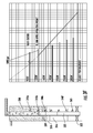
- Figures 3A-3G illustrate an exemplary sequence during a gas lift operation using one embodiment of a gas lift completion system to unload a well 301.
- the gas lift completion system includes a wellhead 312 disposed atop a casing 314 and a production tubing 320 positioned in the casing 314.
- the production tubing 320 may have a plurality of gas lift valves 340 coupled to a respective side pocket mandrel and a production packer 322 at a lower end of the tubing 320.
- the system 300 includes six velocity valves 340a-340f and an orifice valve 365 coupled to the tubing 320.
- the well 301 is loaded with completion fluid, and the gas lift valves 340a-340f are in the open position because no pressure differential exists across the valves 340a-340f.
- injection gas 308 is supplied to assist with unloading of the well 301. Because the gas lift valves 340a-340f are open, the fluid in the annulus 316 is allowed to enter the tubing 320. As more pressure is applied to the casing 314, the fluid level 309 in the annulus 316 will drop. As shown, the fluid level 309 is above the first valve 340a, and the injection gas 308 has not entered the first valve 340a. It must be noted that if the gas lift valves 340a-340f are closed, the annulus fluid may enter the tubing 320 through the orifice valve 365.
- gas injection pressure has increased.
- the injected gas 308 continues to flow in through the first valve 340a, thereby continuing to aerate the fluid column in the tubing 320.
- the fluid in the casing 314 continues to enter the tubing 320 through the orifice valve 365 and/or any of the gas lift valves 340b-340f below the first valve 340a that are open.
- the fluid level 309 has dropped to the depth of the second gas lift valve 340b, and the injected gas 308 has begun to enter the second gas lift valve 340b.
- the first valve 340a has closed due the pressure differential across the first valve 340a.
- the upstream pressure e.g., the pressure at the inlet ports 211
- the downstream pressure e.g., the pressure at the outlet ports 212
- the pressure differential of 2,500 psi (17 MPa) is sufficient to overcome the biasing force of the spring 245, thereby retracting the flow tube 240 and allowing the flapper 230, ball and seat mechanism, a sealing head, or other suitable closure member to close.
- gas injection pressure is increased.
- the injected gas 308 continues to flow in through the second valve 340b, thereby continuing to aerate the fluid column in the tubing 320.
- the fluid in the casing 314 continues to enter the tubing 320 through the orifice valve 365 and/or any of the gas lift valves 340c-340f below the second valve 340b that are open.
- This process of creating a pressure differential to sequentially close an upper valve and causing the fluid level to drop so that injected gas may flow through the next, lower valve continues until injected gas reaches an optimal point of injection.
- the optimal point of injection is a depth in the well where the gas injection point remains stationary until the well condition makes it possible to inject gas deeper. All of the gas lift valves 340a-340f that are above the optimal point of injection have closed due to the pressure differential across the valves.
- Figure 4 illustrates an exemplary embodiment of a gas lift valve 400.
- Figure 4A is an enlarged, partial cross-sectional view of the gas lift valve 400.
- the valve 400 may be positioned in a side pocket mandrel 130 of the gas lift completion system shown in Figure 1 . It must be noted that embodiments of the gas lift valves disclosed herein may be used with other suitable types of gas lift mandrels known to a person of ordinary skill in the art.
- the valve 400 is similar to the valve 200 of Figure 2 in that the valve 400 includes many of the components of the former valve 200.
- One difference between the valves 200, 400 is the axial positions of the components of this valve 400 have been inverted with respect to the latch 416.
- the valve 400 includes a valve housing 410 having one or more gas inlet ports 411 and one or more gas outlet ports 412. As shown, the inlet ports 411 are disposed at a lower portion of the valve 400 and the outlet ports 412 are disposed at an upper portion of the valve 400. A latch 416 is shown disposed at the upper end of the valve 400. In this embodiment, the outlet ports 412 are formed through the latch 416. A sealing member 415 such as a packing stack arrangement may be disposed on each side of the inlet ports 411 to isolate the fluid in the annulus 116 from the tubing 120. The inlet ports 411 and outlet ports 412 communicate via a bore 420 in the valve 400. A closure member 430 is configured to selectively open or close fluid communication through the bore 420.
- Exemplary closure members include a flapper, a ball and seat, a sealing head, and other suitable closure members known to a person of ordinary skill in the art.
- a flapper 430 is positioned at a lower portion of the bore 420.
- the flapper 430 is retained in an open position using a flow tube 440.
- the flow tube 440 is shown biased in an extended position using a biasing member 445 such as a spring.
- the biasing member 445 is disposed in an annular area 447 between the flow tube 440 and the valve housing 410.
- the biasing member 445 may engage an optional spacer member 446 coupled to the flow tube 440.
- a flow control member 450 is coupled to the interior of the flow tube 440.
- the flow control member 450 is an annular ring having an opening 455 therethrough.
- the flow tube 440 is shown as formed using two connected tubulars to facilitate coupling with the flow control member 450, it is contemplated that the flow tube 440 may be formed using a single tubular, or three or more connected tubulars.
- the flow control member 450 forms an effective area in the bore 420 of the flow tube 440.
- the effective area of the flow control member 450 is determined by the difference in area between the inner diameter of the bore 420 and the inner diameter of the opening 455 of the flow control member 450.
- injected fluid flowing in from the inlet ports 411 applies a force to the flow control member 450, which force is opposed by the biasing force of the spring 445.
- the flow tube 440 will compress the spring 445.
- the closing pressure of the flapper 430 can be selected by adjusting the biasing force of the spring 445, the effective area of the flow control member 450, and combinations thereof. After closing, fluid from the annulus 116 is prevented from entering the tubing 120.
- the closing pressure of the flapper 430 can be selected by adjusting the biasing force of the spring 445, the inner diameter of the flow control member 450, and combinations thereof. For example, a smaller diameter opening 455 will close the flapper 430 using a smaller pressure differential than a larger diameter opening 455 when other parameters, such as the flow rate of injected fluid, the biasing force of the spring member 445, and the inner diameter of the bore 420, are fixed.
- the biasing force of the spring member 445, the diameter of the opening 455 and the inner diameter of the bore 420 are fixed, an increase in the flow rate of the injected gas will cause an increase in differential pressure across the flow control member 450, and eventually close the valve 400.
- valve 400 may include an optional bleed port, which may also affect the re-opening of the flapper 430.
- a flapper 430 it must be noted that a ball and seat, a sealing head, or other suitable types of closure members are contemplated.
- the valve 400 may include an optional detent mechanism 453 to retain the flow tube 440 in the retracted position.
- an optional detent mechanism 453 is a retractable pin configured to engage a recess 454 in the flow tube 440.
- Another exemplary detent mechanism is a collet.
- a one-way valve 457 such as a check valve may be disposed at the lower end of the valve 400. The one-way valve 457 may prevent fluid in the tubing 120 from entering the annulus 116 via the valve 400.
- Figures 5 and 6 illustrate an exemplary side pocket mandrel suitable for receiving a gas lift valve.
- Figure 5 depicts a valve 500 disposed in the side pocket mandrel 530
- Figure 6 depicts the valve 500 disposed out of the side pocket mandrel 530.
- the side pocket mandrel 530 may include external check valves disposed at the entrance of the passage into the pocket 532 of the side pocket mandrel 530. Although two passages are shown, it is contemplated that the side pocket mandrel 530 may include a single passage or three or more passages.
- the pocket 532 is configured to receive the valve 500 and is in fluid communication with the tubing 120.
- valve 530 When the valve 530 is not installed, fluid from the tubing 120 may enter the pocket 532, but is prevented from exiting through the passages by the respective check valves.
- the pressure of the injection gas may overcome the check valves, thereby allowing the injection gas to enter the passages and flow toward the gas lift valve 500.
- the injection gas After entering the inlet ports of the gas lift valve 500, the injection gas may exit through the outlet ports, flow through the pocket 532, and flow into the tubing 120, where the injection gas may aerate the fluid column in the tubing 120.
- the injection gas may continue to enter and exit the gas lift valve 500 until the pressure differential across the gas lift valve is sufficient to overcome the biasing force of the biasing member, thereby retracting the flow tube and allowing the flapper to close. It is contemplated that other suitable types of gas lift mandrels known to a person of ordinary skill in the art may be used with embodiments of the gas lift valves disclosed herein.
- the gas lift valves when used in conjunction with the orifice valve, such as a shear-orifice valve, a casing annulus test may be performed without wireline intervention.
- the gas lift valve may include a dampener device to facilitate movement between the open and close position.
- the flow control device of the gas lift valve may include a venturi choke to improve gas passage through the gas lift valve.
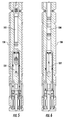
- Figure 7A illustrates an exemplary embodiment of a gas lift valve 700 in an open position.
- Figure 7B illustrates the gas lift valve 700 in a closed position.
- Figure 7C illustrates an exemplary partial, cross-sectional view of the gas lift valve 700.
- the gas lift valve 700 may be positioned in a side pocket mandrel 130 of the gas lift completion system shown in Figure 1 .
- the gas lift valve 700 includes a valve housing 710.
- the valve housing 710 has a bore 720, one or more gas inlet ports 711 and one or more gas outlet ports 712. As shown in Figure 7A , the inlet ports 711 are disposed at a lower portion of the gas lift valve 700 and the outlet ports 712 are disposed at an upper portion of the gas lift valve 700. The inlet ports 711 and outlet ports 712 communicate via the bore 720.
- a flow tube 740 is disposed in the valve housing 710.
- a check valve 757 is disposed in the bore 720. The check valve 757 may prevent fluid in the tubing 120 from entering the annulus 116 via the gas lift valve 700.
- a latch 716 is shown disposed at the upper end of the gas lift valve 700 to allow the gas lift valve 700 be positioned in a side pocket mandrel 130.
- a sealing member 715 such as a packing stack arrangement, may be disposed on each side of the inlet ports 711 to isolate the fluid in the annulus 116 from the tubing 160.
- the flow tube 740 may be formed by a singular tubular or two or more connected tubular.
- the flow tube 740 has a sealing head 730 forming a blind end.
- the sealing head 730 may be formed unitarily on the flow tube 740 or attached to the flow tube 740.
- One or more tube inlets 732 are formed through the flow tube 740 above the sealing head 730.
- the tube inlets 732 provide fluid communication between the inlet ports 711 and the outlet ports 712 through the bore 720.
- a seal member 734 is disposed inside the valve housing 710.
- the sealing head 730 includes an upper end 730U connected to the fluid tube 740 and lower end 730L extending below the upper end 730U.
- the sealing head 730 may include a conical portion so that the outer diameter of the upper end 730U is smaller than the outer diameter of the end 730L.
- the conical portion forms having an inclined surface 730S matching the seal member 734. The sealing head 730 moves relative to the seal member 734 to selectively open or close fluid communication through the bore 720.
- the flow tube 740 includes a flow control member 750 coupled to the interior of the flow tube 740.
- the flow control member 750 is an annular ring having an opening 755 therethrough.
- the flow control member 750 forms an effective area in the flow tube 740.
- the flow tube area may be controlled by selecting the appropriate size of the inner diameter of the opening 755 of the flow control member 750.
- a biasing member 745 is disposed in an annular area 747 between the flow tube 740 and the valve housing 710.
- the flow tube 740 is biased in an open position, as shown in Figure 7A , by the biasing member 745.
- the biasing member 745 may be a spring.
- An optional spacer member 746 coupled to the flow tube 740 may engage the biasing member 745 to adjust the position of the flow tube 740 and the bias force of the biasing member 745.
- the spacer member 746 may be a lock nut.
- the sealing head 730 may move down to re-open the gas lift valve 700 when the casing pressure, tubing pressure, and spring force acting on the effective area of the flow control member 750 in the flow tube 740 dictate.
- the closing pressure differential of the gas lift valve 700 can be adjusted by selecting the biasing force of the spring member 745, the inner diameter of the flow control member 750, and the combinations thereof. For example, a smaller diameter opening 755 will close the sealing head 730 using a smaller pressure differential than a larger diameter opening 755 when other parameters, such as the flow rate of injected fluid and the biasing force of the spring member 745, are fixed. During operation, when the biasing force of the spring member 745 and the diameter of the opening 755 are fixed, an increase in the flow rate of the injected fluid will cause an increase in differential pressure across the flow control member 750, and eventually close the valve 700.
- the closing pressure differential of the gas lift valve 700 can also be adjusted by manipulating the travel distance 733 of the flow tube 740.
- Figure 7D is a partial cross-sectional view of the gas lift valve 700 illustrating the travel distance 733 of the flow tube 740 from the open position to the closed position. The longer the travel distance 733, the more compressed the bias member 745 is at the closed position. When the travel distance 733 is too long, the gas lift valve 700 may not close. When the travel distance 733 is too short, the gas lift valve 700 may close too quickly. Additionally, the relative position between the inlet ports 711 and the tube inlets 732 may affect the closing pressure differential.
- the relative positions of the tube inlets 732, the inlet ports 711, and the lower end 730L of the sealing head 730, and the biasing force of the spring 745 may be pre-set so that the closing pressure differential across the flow control member 750 moves the lower end 730 of the sealing head 730 above the inlet ports 711. Once the sealing head 730 is positioned above the inlet ports 711, the force applied to the large surface area of the lower end 730 by the injected fluid pushes the sealing head 730 further to enable a snap close the valve 700.
- the gas lift valve 700 may include an optional dampener to dampen potential rapid oscillation of the flow tube 740.
- Figure 7E illustrates an exemplary embodiment of a dampener 760 suitable for use with the gas lift valve 700.
- the dampener 760 may be a viscous type dampener disposed in the valve housing 710 under the sealing head 730.
- the dampener 760 may include a cylinder 764 filled with a fluid of high viscosity, such as oil.
- a piston 763 having a restricted flow path is movably disposed in the cylinder 764.
- a shaft 762 extends from the piston 763 out of the cylinder 764 to connect with the sealing head 730.
- the motion of the flow tube 740 urges the piston 763 to move up or down in the cylinder 764, thereby forcing the fluid in the cylinder 764 to flow through the restricted path in the piston 763.
- the fluid flowing through the restricted path dampens rapid oscillation of the flow tube 740.
- FIG. 7F illustrates another exemplary embodiment of a dampener 770 for the gas lift valve 700.
- the dampener 770 may be a friction type dampener.
- the dampener 770 may include a piston 774 disposed in the valve housing 710 below the sealing head 730.
- a shaft structure 772 extends from the piston 774 is coupled to the sealing head 730.
- the motion of the flow tube 740 urges the piston 774 to move up or down in the valve housing 710, thereby generating friction (between the piston 774 and the valve housing 710).
- the friction dampens oscillation of the flow tube 740.
- the gas lift valve 700 may include an optional detent mechanism 753 to retain the flow tube 740 in a fully open or a fully closed position.
- the detent mechanism 753 may include a housing 754 and a spring energized ball structure 758.
- the spring energized ball structure 758 may be fixedly connected to the sealing head 730 by a shaft 756.
- the spring energized ball structure 758 is locked into grooves in the housing 754 to keep the flow tube 740 at the fully open position or the fully closed position.
- the detent mechanism 753 improves flow characteristic through the gas lift valve 700.
- the detent mechanism 753 may also prevent rapid oscillation of the flow tube 740.
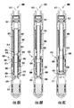
- Figure 8A illustrates another exemplary embodiment of a gas lift valve 800 in an open position.
- Figure 8B illustrates the gas lift valve 800 in a position before a detent is released.
- Figure 8C illustrates the gas lift valve 800 in a closed position.
- the gas lift valve 800 may be positioned in a side pocket mandrel 130 of the gas lift completion system shown in Figure 1 .
- the gas lift valve 800 includes many of the components of the gas lift valve 700.
- One difference between the valves 700, 800 is the gas lift valve 800 includes a detent mechanism that provides valve closure not directly dependent on flow rate.
- the gas lift valve 800 includes a valve housing 810.
- the valve housing 810 has a bore 820, one or more gas inlet ports 811 and one or more gas outlet ports 812.
- the inlet ports 811 are disposed at a lower portion of the gas lift valve 800 and the outlet ports 812 are disposed at an upper portion of the gas lift valve 800.
- the inlet ports 811 and outlet ports 812 communicate via the bore 820.
- a flow tube 840 is disposed in the valve housing 810.
- a check valve 857 is disposed in the bore 820. The check valve 857 may prevent fluid in the tubing 120 from entering the annulus 116 via the gas lift valve 800.
- a sealing member 815 such as a packing stack arrangement, may be disposed on each side of the inlet ports 811 to isolate the fluid in the annulus 116 from the tubing 160.
- the flow tube 840 includes a lower flow tube assembly 880 and an upper flow tube assembly 886.
- the lower flow tube assembly 880 overlaps with the upper flow tube assembly 886 in the middle section where the lower flow tube assembly 880 encases the upper flow tube assembly 886.
- the lower flow tube assembly 880 and the upper flow tube assembly 886 may move relative to each other changing the length of the overlapping section.
- Each of the flow tube assemblies 880, 886 may be formed by a singular tubular or two or more connected tubular.
- the lower flow tube assembly 880 has a sealing head 830 forming a blind end.
- the sealing head 830 may be formed unitarily on an end section of the lower flow tube assembly 880 or attached to the lower flow tube assembly 880.
- One or more tube inlets 832 are formed through the lower flow tube assembly 880 above the sealing head 830.
- the tube inlets 832 provide fluid communication between the inlet ports 811 and the outlet ports 812 through the bore 820.
- a seal member 834 is disposed inside the valve housing 810.
- the sealing head 830 has an inclined surface matching the seal member 834. The sealing head 830 moves relative to the seal member 834 to selectively open or close fluid communication through the bore 820.
- a flow control member 850 is coupled to the interior of the upper flow tube assembly 886.
- the flow control member 850 is an annular ring having an opening 855 therethrough.
- the flow control member 850 forms a restricted area in the flow tube 840.
- the flow tube area may be controlled by selecting the appropriate size of the inner diameter of the opening 855 of the flow control member 850.
- a biasing member 845 is disposed around the upper flow tube assembly 886 in an annular area 847 between the flow tube 840 and the valve housing 810.
- the biasing member 845 may be a spring compressed to bias the sealing head 830 to an open position, as shown in Figure 8A .
- An optional spacer member 846 coupled to the upper flow tube assembly 886 may engage the biasing member 845 to adjust the position of the sealing head 830 and the bias force of the biasing member 845.
- the spacer member 846 may be a lock nut.
- the gas lift valve 800 also includes a detent mechanism 853 to retain the lower flow tube assembly 880 along with the sealing head 830 in a fully open position.
- the detent mechanism 853 may include a retractable pin 884.
- the retractable pin 884 may extend through an opening in the lower flow tube assembly 880 to lock the lower flow tube assembly 880 at the open position, as shown in Figure 8A .
- the retractable pin 884 may retract from the lower flow tube assembly 880 by a release mechanism 885.
- the release mechanism 885 may be a protrusion on the upper flow tube assembly 886.
- a detent spring 882 is compressed at the open position and biases the lower fluid tube assembly 880 towards the closed position. The detent spring 882 enables the gas lift valve 800 to snap close when the detent mechanism 853 is released.
- the detent mechanism 853 provides fast valve closure and prevents the gas lift valve 800 from oscillation from fluctuation of flow rate through the gas lift valve 800. Once the pressure below the sealing head 830 is reduced or equalized, the biasing member 845 will push the upper flow tube assembly 886 and lower flow tube assembly 880 downward to re-open the gas lift valve 800 and the detent mechanism 853 will automatically re-lock the gas lift valve 800 at the open position.
- Figure 9A illustrates an exemplary embodiment of a gas lift valve 900 in an open position.
- Figure 9B illustrates the gas lift valve 900 in a closed position.
- the gas lift valve 900 may be positioned in a side pocket mandrel 130 of the gas lift completion system shown in Figure 1 .
- the gas lift valve 900 is similar to the gas lift valve 700.
- the difference between the gas lift valve 900 and the gas lift valve 700 is that that gas lift valve 900 includes a ball and seat closure member.
- the gas lift valve 900 includes a valve housing 910.
- the valve housing 910 has a bore 920, one or more gas inlet ports 911 and one or more gas outlet ports 912. As shown in Figure 9A , the inlet ports 911 are disposed at a lower portion of the gas lift valve 900 and the outlet ports 912 are disposed at an upper portion of the gas lift valve 900. The inlet ports 911 and outlet ports 912 communicate via the bore 920.
- a flow tube 940 is disposed in the valve housing 910.
- a check valve 957 is disposed in the bore 920. The check valve 957 may prevent fluid in the tubing 120 from entering the annulus 116 via the gas lift valve 900.
- a latch 916 is shown disposed at the upper end of the gas lift valve 900 to allow the gas lift valve 900 be positioned in a side pocket mandrel 130.
- the flow tube 940 may be formed by a singular tubular or two or more connected tubular.
- a closure member 930 is disposed in the valve housing 910. As shown in Figure 9A , the closure member 930 may be a ball having a central through hole 935 for selectively to allow fluid flow and an outer slot 933 to engage an actuator.
- the flow tube 940 may include one or more pins 943 positioned to engage with the closure member 930. The one or more pins 943 may insert into the outer slot 933 of the closure member 930 so that vertical movement of the pins 943 rotates the closure member 930 to selectively open or close fluid communication through the bore 920.
- the flow tube 940 includes a flow control member 950 coupled to the interior of the flow tube 940 of the flow tube 940.
- the flow control member 950 may be an annular ring having an opening 955 therethrough.
- the flow control member 950 forms a choke in the flow tube 940.
- the effective area of the choke may be controlled by selecting the appropriate size of the inner diameter of the opening 955 of the flow control member 950.
- a biasing member 945 is disposed in an annular area 947 between the flow tube 940 and the valve housing 910.
- the flow tube 940 is biased in an open position, as shown in Figure 9A , by the biasing member 945.
- the biasing member 945 may be a spring.
- An optional spacer member 946 coupled to the flow tube 940 may engage the biasing member 945 to adjust the position of the flow tube 940 and the bias force of the biasing member 945.
- the spacer member 946 may be a lock nut.
- Embodiments of the present disclosure provide a valve apparatus configured to close when a predetermined pressure differential across the valve apparatus is reached. Because the valve apparatus does not depend on bellows, the valve apparatus may be used in high injection pressure and/or high injection rate, and/or high injection volume applications and is suitable for most deepwater applications.
- the valve apparatus is capable of withstanding extremely high pressures, e.g., from about 1,000 psi (6.9 MPa) to about 10,000 psi (69 MPa), from about 5,000 psi (34 MPa) to about 10,000 psi (69 MPa), from about 7,000 psi (48 MPa) to 10,000 psi (69 MPa), at least 7,000 psi (48 MPa), or at least 10,000 psi (69 MPa).
- extremely high pressures e.g., from about 1,000 psi (6.9 MPa) to about 10,000 psi (69 MPa), from about 5,000 psi (34 MPa) to about 10,000 psi (69 MPa), from about 7,000 psi (48 MPa) to 10,000 psi (69 MPa), at least 7,000 psi (48 MPa), or at least 10,000 psi (69 MPa).
- valve apparatus is capable of withstanding injection rates from about 0.5 to about 15 million cubic feet (about 1.4x10 4 to about 4.2x10 5 m 3 ) per day; preferably from about 7.5 to about 15 million cubic feet (about 2.1x10 5 to about 4.2x10 5 m 3 ) per day.
- One embodiment of the present disclosure provides a method for performing downhole gas lift operations.
- the method includes coupling a gas lift valve to a tubing, wherein the gas lift valve comprises an actuator, a flow control member disposed in the actuator, and a closure member that is initially in an open position, injecting a gas downhole and exterior to the tubing, urging the gas to enter the tubing via the gas lift valve, and creating a sufficient pressure differential across the gas lift valve to move the actuator, thereby causing the closure member to close the gas lift valve.
- the gas lift valve further includes a housing having an inlet and an outlet, and biasing member for biasing the actuator in an extended position, wherein the closure member is configured to selectively close a bore through the housing, the actuator is movable between the extended position and a retracted position, and the actuator, when in the extended position, retains the closure member in an open position.
- the actuator comprises a flow tube, and the flow control member is coupled to an interior of the flow tube.
- the closure member is a sealing head disposed at one end of the flow tube.
- the closure member is selected from a flapper, a sealing head on the actuator, and a ball and seat.
- a plurality of gas lift valves is coupled to the tubing and axially spaced apart along the tubing.
- the method further comprises sequentially closing the plurality of gas lift valves.
- the method further comprises flowing the gas through a first gas lift valve and flowing a liquid through a second gas lift valve.
- the method includes urging a liquid to enter the tubing via an orifice valve in fluid communication with the tubing.
- the orifice valve is disposed below the gas lift valve.
- a closing pressure differential is adjustable by adjusting a force of the biasing member and/or a travel distance of the actuator between the extended position and the open position.
- the method includes increasing the pressure differential by decreasing the pressure downstream from the gas lift valve.
- the actuator comprises a flow tube, and the flow control member is disposed in an interior of the flow tube.
- a method for performing downhole gas lift operations includes coupling a gas lift valve to a tubing, wherein the gas lift valve comprises an actuator, a flow control member disposed in the actuator, and a closure member that is initially in an open position, injecting a gas downhole and interior to the tubing, urging the gas to exit the tubing via the gas lift valve, and creating a sufficient pressure differential across the gas lift valve to move the actuator, thereby causing the closure member to close the gas lift valve.
- a valve for controlling fluid flow includes a housing having a bore in fluid communication with an inflow port and an outlet port, a closure member configured to close fluid communication through the bore, a flow tube movable between an extended position and a retracted position, and a flow control device disposed in the flow tube, wherein when in the extended position, the flow tube retains the closure member in an open position, and wherein the flow tube is movable to the retracted position in response to a predetermined pressure differential across the bore.
- the valve further comprises a biasing member for biasing the flow tube in the extended position.
- the flow control device provides an effective area for urging the flow tube toward the retracted position in response to the pressure differential.
- the valve further comprises a detent mechanism for retaining the flow tube in the retracted position or the extended position.
- the valve further comprises a latch member.
- the outlet port is formed through the latch member.
- the closure member is selected from the group consisting of a flapper, a sealing head on the flow tube, and a ball and seat.
- the closure member comprises a sealing head attached to the flow tube.
- the valve further comprises a seal member disposed in the housing, wherein the sealing head moves relative to the seal member to selectively open or close fluid communication through the valve.
- the flow tube includes one of more tube inlets adjacent to the sealing head.
- the valve further comprises a dampener attached to the sealing head.
- the valve further comprises a check valve disposed adjacent the outlet port.
- the valve further comprises a dampener coupled to the flow tube.
- the flow control device is fixedly coupled to the flow tube.
- the flow control device comprises an annular ring coupled to an interior of the flow tube.
- a re-open pressure is determined by an inner diameter of the bore, an inner diameter of the flow control device, and a force of the biasing member.
- the valve is configured to operate in an external pressure from about 1,000 psi (6.9 MPa) and about 10,000 psi (69 MPa).
- the valve is configured to operate with an injection gas rate from about 0.5 to about 15 million cubic feet (about 1.4x10 4 to about 4.2x10 5 m 3 ) per day.
Landscapes
- Engineering & Computer Science (AREA)
- Geology (AREA)
- Life Sciences & Earth Sciences (AREA)
- Mining & Mineral Resources (AREA)
- Environmental & Geological Engineering (AREA)
- Fluid Mechanics (AREA)
- Physics & Mathematics (AREA)
- General Life Sciences & Earth Sciences (AREA)
- Geochemistry & Mineralogy (AREA)
- Mechanical Engineering (AREA)
- General Engineering & Computer Science (AREA)
- Lift Valve (AREA)
- Check Valves (AREA)
- Fluid-Driven Valves (AREA)
Applications Claiming Priority (2)
| Application Number | Priority Date | Filing Date | Title |
|---|---|---|---|
| US201361881663P | 2013-09-24 | 2013-09-24 | |
| US201462001448P | 2014-05-21 | 2014-05-21 |
Publications (2)
| Publication Number | Publication Date |
|---|---|
| EP2863006A2 true EP2863006A2 (de) | 2015-04-22 |
| EP2863006A3 EP2863006A3 (de) | 2015-12-23 |
Family
ID=51609949
Family Applications (1)
| Application Number | Title | Priority Date | Filing Date |
|---|---|---|---|
| EP14185861.3A Withdrawn EP2863006A3 (de) | 2013-09-24 | 2014-09-22 | Gasliftventil |
Country Status (3)
| Country | Link |
|---|---|
| US (1) | US20150083433A1 (de) |
| EP (1) | EP2863006A3 (de) |
| BR (1) | BR102014023581A2 (de) |
Families Citing this family (5)
| Publication number | Priority date | Publication date | Assignee | Title |
|---|---|---|---|---|
| WO2016191584A1 (en) * | 2015-05-26 | 2016-12-01 | Weatherford Technology Holdings, Llc | Tubing mounted injection valve |
| US11359469B2 (en) * | 2017-09-12 | 2022-06-14 | Liberty Lift Solutions, LLC | System for gas lift and method of use |
| US10787889B2 (en) | 2018-07-26 | 2020-09-29 | Weatherford Technology Holdings, Llc | Gas lift valve having shear open mechanism for pressure testing |
| WO2022040252A1 (en) * | 2020-08-18 | 2022-02-24 | Schlumberger Technology Corporation | Scale resistant backcheck valve |
| WO2023010108A1 (en) * | 2021-07-29 | 2023-02-02 | Schlumberger Technology Corporation | Sliding sleeve for gas lift system |
Family Cites Families (11)
| Publication number | Priority date | Publication date | Assignee | Title |
|---|---|---|---|---|
| US3386391A (en) * | 1966-09-06 | 1968-06-04 | Henry U. Garrett | Well apparatus and method |
| US3642070A (en) * | 1970-05-06 | 1972-02-15 | Otis Eng Co | Safety valve system for gas light wells |
| US3888273A (en) * | 1974-01-21 | 1975-06-10 | Dresser Ind | Variable orifice gas lift valve |
| US3937280A (en) * | 1975-02-03 | 1976-02-10 | Macco Oil Tool Company, Inc. | Artificial lift well apparatus |
| US4489743A (en) * | 1982-07-29 | 1984-12-25 | Otis Engineering Corporation | Differential gas lift valve |
| US4791990A (en) * | 1986-05-27 | 1988-12-20 | Mahmood Amani | Liquid removal method system and apparatus for hydrocarbon producing |
| US5522418A (en) * | 1994-11-08 | 1996-06-04 | Johnson; Larry | Differential pressure operated gas lift valve |
| US6932581B2 (en) * | 2003-03-21 | 2005-08-23 | Schlumberger Technology Corporation | Gas lift valve |
| CA2559799C (en) * | 2004-03-22 | 2013-02-19 | Shell Canada Limited | Method of injecting lift gas into a production tubing of an oil well and gas lift flow control device for use in the method |
| US7360602B2 (en) * | 2006-02-03 | 2008-04-22 | Baker Hughes Incorporated | Barrier orifice valve for gas lift |
| US7766085B2 (en) * | 2008-02-04 | 2010-08-03 | Marathon Oil Company | Apparatus, assembly and process for injecting fluid into a subterranean well |
-
2014
- 2014-09-22 EP EP14185861.3A patent/EP2863006A3/de not_active Withdrawn
- 2014-09-23 US US14/493,505 patent/US20150083433A1/en not_active Abandoned
- 2014-09-23 BR BR102014023581A patent/BR102014023581A2/pt not_active Application Discontinuation
Non-Patent Citations (1)
| Title |
|---|
| None |
Also Published As
| Publication number | Publication date |
|---|---|
| EP2863006A3 (de) | 2015-12-23 |
| US20150083433A1 (en) | 2015-03-26 |
| BR102014023581A2 (pt) | 2015-10-06 |
Similar Documents
| Publication | Publication Date | Title |
|---|---|---|
| US10294755B2 (en) | Dual barrier injection valve with a variable orifice | |
| US9334709B2 (en) | Tubing retrievable injection valve assembly | |
| US9546537B2 (en) | Multi-positioning flow control apparatus using selective sleeves | |
| US8443901B2 (en) | Inflow control device and methods for using same | |
| CA2746623C (en) | Injection valve | |
| US9816352B2 (en) | Tubing pressure operated downhole fluid flow control system | |
| US9157297B2 (en) | Pump-through fluid loss control device | |
| US9624755B2 (en) | Wireline retrievable injection valve assembly with a variable orifice | |
| US20130228341A1 (en) | Downhole Fluid Flow Control System Having Pressure Sensitive Autonomous Operation | |
| EP2863006A2 (de) | Gasliftventil | |
| AU2012371604A1 (en) | Downhole fluid flow control system having pressure sensitive autonomous operation | |
| US20170350220A1 (en) | Wellbore plug with a rotary actuated variable choke | |
| US20170356272A1 (en) | Subsurface injection valve system | |
| WO2016172736A1 (en) | Dual barrier injection valve with a variable orifice | |
| US9506323B2 (en) | Downhole system having chemical injection valve assembly and method of chemical injection |
Legal Events
| Date | Code | Title | Description |
|---|---|---|---|
| PUAI | Public reference made under article 153(3) epc to a published international application that has entered the european phase |
Free format text: ORIGINAL CODE: 0009012 |
|
| 17P | Request for examination filed |
Effective date: 20140922 |
|
| AK | Designated contracting states |
Kind code of ref document: A2 Designated state(s): AL AT BE BG CH CY CZ DE DK EE ES FI FR GB GR HR HU IE IS IT LI LT LU LV MC MK MT NL NO PL PT RO RS SE SI SK SM TR |
|
| AX | Request for extension of the european patent |
Extension state: BA ME |
|
| PUAL | Search report despatched |
Free format text: ORIGINAL CODE: 0009013 |
|
| AK | Designated contracting states |
Kind code of ref document: A3 Designated state(s): AL AT BE BG CH CY CZ DE DK EE ES FI FR GB GR HR HU IE IS IT LI LT LU LV MC MK MT NL NO PL PT RO RS SE SI SK SM TR |
|
| AX | Request for extension of the european patent |
Extension state: BA ME |
|
| RIC1 | Information provided on ipc code assigned before grant |
Ipc: E21B 43/12 20060101AFI20151116BHEP |
|
| STAA | Information on the status of an ep patent application or granted ep patent |
Free format text: STATUS: THE APPLICATION IS DEEMED TO BE WITHDRAWN |
|
| 18D | Application deemed to be withdrawn |
Effective date: 20160624 |