EP2863009A2 - Struktur zur Verringerung der Tunnelmikrodruckwelle mit Luftleitung - Google Patents
Struktur zur Verringerung der Tunnelmikrodruckwelle mit Luftleitung Download PDFInfo
- Publication number
- EP2863009A2 EP2863009A2 EP20140188267 EP14188267A EP2863009A2 EP 2863009 A2 EP2863009 A2 EP 2863009A2 EP 20140188267 EP20140188267 EP 20140188267 EP 14188267 A EP14188267 A EP 14188267A EP 2863009 A2 EP2863009 A2 EP 2863009A2
- Authority
- EP
- European Patent Office
- Prior art keywords
- air pipe
- section
- pressure wave
- micro pressure
- reducing
- Prior art date
- Legal status (The legal status is an assumption and is not a legal conclusion. Google has not performed a legal analysis and makes no representation as to the accuracy of the status listed.)
- Granted
Links
Images




Classifications
-
- E—FIXED CONSTRUCTIONS
- E21—EARTH OR ROCK DRILLING; MINING
- E21F—SAFETY DEVICES, TRANSPORT, FILLING-UP, RESCUE, VENTILATION, OR DRAINING IN OR OF MINES OR TUNNELS
- E21F1/00—Ventilation of mines or tunnels; Distribution of ventilating currents
- E21F1/003—Ventilation of traffic tunnels
-
- B—PERFORMING OPERATIONS; TRANSPORTING
- B61—RAILWAYS
- B61B—RAILWAY SYSTEMS; EQUIPMENT THEREFOR NOT OTHERWISE PROVIDED FOR
- B61B13/00—Other railway systems
- B61B13/10—Tunnel systems
-
- E—FIXED CONSTRUCTIONS
- E21—EARTH OR ROCK DRILLING; MINING
- E21D—SHAFTS; TUNNELS; GALLERIES; LARGE UNDERGROUND CHAMBERS
- E21D9/00—Tunnels or galleries, with or without linings; Methods or apparatus for making thereof; Layout of tunnels or galleries
- E21D9/14—Layout of tunnels or galleries; Constructional features of tunnels or galleries, not otherwise provided for, e.g. portals, day-light attenuation at tunnel openings
-
- E—FIXED CONSTRUCTIONS
- E21—EARTH OR ROCK DRILLING; MINING
- E21F—SAFETY DEVICES, TRANSPORT, FILLING-UP, RESCUE, VENTILATION, OR DRAINING IN OR OF MINES OR TUNNELS
- E21F17/00—Methods or devices for use in mines or tunnels, not covered elsewhere
Definitions
- the embodiments described herein pertain generally to a structure for reducing tunnel micro pressure wave including an air pipe.
- a pressure wave is formed. Such a pressure wave is propagated into the tunnel to be emitted outward in a micro pressure wave form through a tunnel exit. Since the micro pressure wave causes impulsive noise and low frequency vibration to peripheral private houses, it is highly important to reduce the micro pressure wave in designing a railroad tunnel.
- a hood having an arch-shaped cross section has been conventionally provided at an entry of a railroad tunnel.
- Such a hood has been significantly effective in reducing the micro pressure wave.
- the first aspect of the present invention provides a structure for reducing a tunnel micro pressure wave, comprising: a hood structure formed in front of an entry of a railroad tunnel; and an air pipe section in which at least one air pipe is provided along the circumference of the hood structure; wherein the air pipe comprises a horizontal introduction section formed to be extended from an internal side of the hood structure toward a longitudinal direction of the hood structure, an outlet section formed on an external side of the hood structure, and an intermediate section connecting the horizontal introduction section and the outlet section through each other.
- the present invention provides a structure for reducing a tunnel micro pressure wave including an air pipe, which is capable of more effectively reducing the tunnel micro pressure wave.
- the horizontal introduction section, the outlet section and the intermediate section form a flow path, which reflects at least part of a compressional wave passing through the sections as an expansion wave.
- the air pipe section comprises an air pipe, which is provided in plural numbers with intervals along the longitudinal direction of the hood structure.
- the hood structure comprises a plural number of hoods, which are divided and arranged to be spaced with a gap along the longitudinal direction; the air pipe section further comprises a filling section formed to close a remaining area of the gap where no air pipe is provided, formed in the gap.
- the outlet section comprises an air pipe, which is extended in the same direction as the direction, toward the intermediate section is extended, or bent and extended in a backward direction.
- the outlet section comprises an air pipe, of which end is opened toward an upper side or a backward direction.
- the air pipe is an air pipe provided in at least one position of a left side portion, a right side portion, and a top portion of the air pipe section.
- the outlet section is extended in the same direction as the direction, toward which the intermediate section is extended, and the end of the outlet section is opened toward a backward direction.
- the intermediate section is perpendicular or diagonal to a wall of the hood structure.
- the air pipe comprises a partition section for partitioning the horizontal introduction section, the outlet section and the intermediate section.
- the structure for reducing a tunnel micro pressure wave further comprises a cap section, which is capable of selectively closing the rear end of the outlet section.
- a method for reducing a tunnel micro pressure wave comprising: providing a hood structure in front of an entry of a railroad tunnel; and providing at least one air pipe of an air pipe section along the circumference of the hood structure; wherein the air pipe comprises a horizontal introduction section formed to be extended from an internal side of the hood structure toward a longitudinal direction of the hood structure, an outlet section formed on an external side of the hood structure, and an intermediate section connecting the horizontal introduction section and the outlet section through each other.
- the method further comprises introducing a micro pressure wave to the horizontal introduction section of the air pipe and passing the micro pressure wave through the air pipe.
- the method further comprises reflecting at least a part of the micro pressure wave at the outlet section of the air pipe.
- the method further comprises tuning the air pipe by selectively closing a rear end of the outlet section of the air pipe.
- a structure for reducing a tunnel micro pressure wave may includes a hood structure formed in front of an entry of a railroad tunnel; and an air pipe section in which at least one air pipe is provided along the circumference of the hood structure, wherein the air pipe comprises a horizontal introduction section formed to be extended from an internal side of the hood structure toward a longitudinal direction of the hood structure, an outlet section formed on an external side of the hood structure, and an intermediate section connecting the horizontal introduction section and the outlet section through each other.
- connection to or coupled to are used to designate a connection or coupling of one element to another element and include both a case where an element is “directly connected or coupled to” another element and a case where an element is “electronically connected or coupled to” another element via still another element.
- the term "on” that is used to designate a position of one element with respect to another element includes both a case that the one element is adjacent to the another element and a case that any other element exists between these two elements.
- the term “comprises or includes” and/or “comprising or including” used in the document means that one or more other components, steps, operations, and/or the existence or addition of elements are not excluded in addition to the described components, steps, operations and/or elements.
- the terms “about or approximately” or “substantially” are intended to have meanings close to numerical values or ranges specified with an allowable error and intended to prevent accurate or absolute numerical values disclosed for understanding of the present invention from being illegally or unfairly used by any unconscionable third party.
- the term “step of” does not mean “step for.”
- the 9 o'clock direction may be substantially a forward direction
- the 3 o'clock direction may be substantially a backward direction
- a portion toward the 12 o'clock direction may be substantially a left side portion
- a portion toward the 6 o'clock direction may be substantially a right side portion
- the 12 o'clock direction may be substantially an upper side; and others.
- Example embodiments relate to a structure for reducing a tunnel micro pressure wave including an air wave.
- the structure for reducing a tunnel micro pressure wave including an air pipe in accordance with an example embodiment (hereinafter referred to as the "present structure for reducing a tunnel micro pressure wave”) will be described.
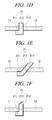
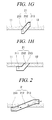
- FIG. 1 is a schematic conceptual view illustrating various example embodiments of an air pipe in accordance with an example embodiment
- FIG. 2 is a conceptual view for depiction of a function of an air pipe
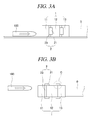
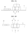
- FIG. 3 to FIG. 12 are conceptual views illustrating various example embodiments of a structure for reducing a tunnel micro pressure wave including an air pipe in accordance with an example embodiment
- FIG. 13 is a schematic conceptual view for depiction of a cap section.
- (a) of each of FIG. 3 to FIG. 12 is a side view when viewed from the right side
- (b) of each of FIG. 3 to FIG. 12 is a plane view.
- the present structure for reducing a tunnel micro pressure wave includes a hood structure 1 and an air pipe section 2.
- the hood structure 1 is formed in front of an entry of a railroad tunnel 0.
- the hood structure 1 may be formed with a passageway, through which a railroad car 100 can enter into the entry of the railroad tunnel 0.
- a transversal cross section of the hood structure 1 may be, for example, of polygonal shapes such as a hoof shape, a tetragonal shape and a heptagonal shape, or an arch shape.
- shape of the transversal cross section of the hood structure 1 is not limited to the above-described shapes, and the transversal cross section of the hood structure 1 may be of various shapes according to construction conditions, necessity for reduction of a tunnel micro pressure wave, and so on.
- the air pipe section 2 is provided with at least one air pipe 21 along the circumference of the hood structure 1.
- the air pipe 21 includes a horizontal introduction section 211, an outlet section 213 and an intermediate section 212.
- the present structure for reducing a tunnel micro pressure wave enables a tunnel micro pressure wave to be emitted or a compressional wave pressure slope to be decreased along a path formed by the components of the air pipe 21.
- a compressional wave to be developed in a traveling direction of a railroad car is directly introduced for emission through the horizontal introduction section 211 formed to be extended in a longitudinal direction or a pressure slope of a compressional wave can be decreased. Accordingly, the effect in reducing a tunnel micro pressure wave can be maximized.
- the horizontal introduction section 211 of the air pipe 21 is formed while being extended from an internal side of the hood structure 1 toward a longitudinal direction.
- the horizontal introduction section 211 is horizontally formed, but may be formed to be somewhat diagonal to a horizontal direction depending on slope of a traveling route of a railroad car. Or, the horizontal introduction section 211 may be horizontally formed, irrespective of the slope of the traveling route of a railroad car.
- the outlet section 213 is formed on an external side of the hood structure 1, and the intermediate section 212 connects the horizontal introduction section 211 and the outlet section 213 through each other.
- the direction of the horizontal introduction section 211 which is formed while being extended from an internal side of the hood structure 1 toward a longitudinal direction (forward and backward direction), may be parallel with the traveling direction of the railroad car 100 passing through the hood structure 1.
- a compressional wave formed by the railroad car 100 passing through the hood structure 1 is developed (moves) in parallel with the traveling direction of the railroad car 100, the compressional wave can be directly introduced into the horizontal introduction section 211. Accordingly, effective reduction of compressional wave pressure slope and a tunnel micro pressure wave can be realized.
- the 6 o'clock direction corresponds to the internal side of the hood structure 1
- the 12 o'clock direction corresponds to the external side of the hood structure 1.
- the intermediate section 212 may be a portion formed passing through the hood structure 1.
- the intermediate section 212 may be formed passing through the wall of the hood structure 1.
- FIG. 1 illustrates various example embodiments of the air pipe 21 of the air pipe section 2 formed between the first hood 11 and the second hood 12 of the multiple hoods 11, 12, 13.
- the intermediate section 212 may be formed to be perpendicular to the wall of the hood structure 1.
- the intermediate section 212 may be formed to be diagonal to the wall of the hood structure 1.
- an angle (an angle formed substantially in the 4 o'clock direction with reference to FIG. 4 ) formed by the direction, toward which the intermediate section 212 is formed, and the direction (longitudinal direction), toward which the hood structure 1 is formed, is an acute angle.
- the outlet section 213 may be formed to be extended from the intermediate section 212 toward the same direction as the direction, toward which the intermediate section 212 is extended.
- the outlet section 213 may be formed to be bent and extended from the intermediate section 212 toward a backward direction.
- the outlet section 213 may be bent and extended from the intermediate section 212, which is formed to be diagonally extended, toward the backward direction.
- the outlet section 213 may be orthogonally bent and extended from the intermediate section 212, which is formed to be perpendicularly extended to the wall of the hood structure 1, toward the backward direction.
- the outlet section 213 may be a hole formed on an external surface of the hood structure 1.
- the configuration that the outlet section 213 is formed on the external side of the hood structure 1 includes not only the configuration that the outlet section 213 is extended from the intermediate section 213 to be protruded from the external surface of the hood structure 1, as illustrated in (a) to (g) of FIG. 1 , but also the configuration that the outlet section 213 is formed in the shape of a hole on the external surface of the hood structure 1, as illustrated in (h) of FIG. 1 .
- the horizontal introduction section 211, the outlet section 213 and the intermediate section 212 may form a flow path.
- the flow path is capable of reflecting at least part of a compressional wave passing through the flow path as an expansion wave.
- part of a compressional wave which is introduced into the horizontal introduction section 211 to be transferred to the intermediate section 212 and the outlet section 213, may be reflected in the form of an expansion wave at the outlet section 213.
- the air pipe 21 may emit a compressional wave, and furthermore, serve as a compressional wave reflection duct, which results in offset or decrease of a compressional wave within the hood structure by returning part of a compressional wave propagated into the air pipe 21.
- FIG. 2 is a conceptual view using the air pipe illustrated in (a) of FIG. 1 for depiction of the function of the air pipe 2.
- the outlet section 213 may be of the shape that can most effectively reduce a tunnel micro pressure wave.
- the shape of the outlet section 213 may be designed and formed to maximize the effect of reduction of a tunnel micro pressure wave (maximize emission of a compressional wave and offset or decrease of a compressional wave) in consideration of a size of the hood structure 1, a size of the railroad tunnel 0, a speed of the railroad car 100 passing through the tunnel.
- the end of the outlet section 213 may be of a shape opened toward the backward direction, or with reference to (d) and (e) of FIG. 1 , the end of the outlet section 213 may be of a shape opened toward the upper side.
- the air pipe 21 may be provided in at least one of a left side portion, a right side portion and an upper portion of the air pipe section 2.
- the outlet section 213 may be formed in various shapes in a design aspect.
- the outlet section 213 may be formed in the shape that the end of the outlet section 213 has a tail part being extended to traverse the upward and downward direction, like the uppermost one of the air pipes 21 illustrated in (a) of FIG. 9 .
- the air pipe 21 may be provided in each of the left and right side portions of the air pipe section 2.
- the air pipe 21 may be provided at the top portion of the air pipe section 2.
- the air pipe 21 may be provided in each of the left and right side portions and the top portion of the air pipe section 2.
- the outlet section 213 of the air pipe 21 may be extended in the same direction as the direction, toward which the intermediate section 212 is extended, and the end of the outlet section 213 may be of a shape opened toward the backward direction [refer to (f) of FIG. 1 ].
- one air pipe 21 may be provided in each of left and right side portions.
- a longitudinal cross section of c of each of FIG. 3 to FIG. 5 may be, for example, (a) of FIG. 1 .
- a filling section 23 may be formed in the remaining area of the circumference of the hood structure 1 where the air pipes 21 are not formed, as illustrated in the drawing.
- one air pipe 21 provided in each of the left and right side portions may include partition sections 22 simultaneously partitioning the horizontal introduction section 211, the outlet section 213 and the intermediate section 212. Accordingly, each of the air pipes 21 may be formed with a multiple number of flow paths.
- a multiple number of flow paths may be formed by applying partition sections 22 forming partition walls along the longitudinal direction to the air pipe 21 forming one flow path.
- the air pipe 21 may be formed in multiple numbers in each of the left and right side portions.
- the longitudinal cross section of c of FIG. 6 may be, for example, (b) of FIG. 1 .
- the longitudinal cross section of c of each of FIG. 7 to FIG. 9 may be, for example, one of (b), (c), and (g) of FIG. 1 .
- the longitudinal cross section of c of FIG. 10 may be, for example, (d) or (e) of FIG. 1 .
- longitudinal lengths of the multiple number of the air pipes 21 may be identical to one another, as illustrated in (a) of FIG. 6 .
- the longitudinal lengths of the multiple number of the air pipes 21 may be different from one another, as illustrated in (a) of each of FIG. 7 to FIG. 9 .
- the longitudinal lengths of the multiple number of the air pipes 21 may increase as their positions are close to the upper side, compared to the longitudinal lengths of the air pipes 21 close to the lower side.
- the longitudinal lengths of the air pipes 21 may be constant, when viewed from the side surface.
- a length of an upper end of one air pipe 21 may be longer than a length of a lower end thereof, when viewed from the side surface.
- the air pipe 21 may be provided in the top portion.
- one air pipe 21 may be provided on the top portion of the air pipe section 2.
- the air pipes 21 may be provided in multiple numbers on the top portion of the air pipe section 2 along the transverse direction.
- the air pipe 21 provided in the top portion may be of the same shape as illustrated in (f) of FIG. 1 .
- the present structure for reducing a tunnel micro pressure wave may include a cap section 3, which is capable of selectively closing the rear end of the outlet section 213.
- the cap section 3 may close the rear end of the flow path.
- FIG. 13 illustrates that the air pipe 21 illustrated in (d) of FIG. 1 is provided with the cap section 3
- (b) of FIG. 13 illustrates that the air pipe 21 illustrated in (b) of FIG. 1 is provided with the cap section 3
- (c) of FIG. 13 illustrates that the air pipe 21 illustrated in (f) of FIG. 1 is provided with the cap section 3.
- the cap section 3 may be detachable. Accordingly, tuning the air pipe section 2 is possible.
- the air pipe section may be tuned, by closing at least one of the opened air pipes 21 with the cap section 3, or opening at least one of the closed air pipes 21. Accordingly, the effect in reducing a tunnel micro pressure wave can be further improved.
- At least one of the air pipes 21 may be closed with the cap section 3, or the closed air pipes 21 may be opened, such that the effect in reducing a tunnel micro pressure wave can be maintained or improved even in case of the change in environments.
- air pipe section 2 may be provided in multiple numbers along the longitudinal direction with intervals.
- FIG. 3 to FIG. 12 illustrate the present structure for reducing a tunnel micro pressure wave, wherein two (2) air pipe sections 2 are provided along the longitudinal direction with intervals.
- the hood structure 1 may be formed to be divided into a multiple number of portions along the longitudinal direction.
- the hood structure 1 may include a multiple number of hoods 11, 12, 13 arranged while being spaced with gaps along the longitudinal direction.
- the multiple hoods 11, 12, 13 may form a passageway, through which the railroad car 100 can enter into the entry of the railroad tunnel 0.
- the hood structure 1 may be provided with three (3) hoods 11, 12, 13, but not limited thereto.
- the multiple hoods may be two, three, or more, unlike the drawings.
- the specific number of the hoods is preferably set in the direction, toward which the air pipe section 2 is provided, so as to maximize the effect in reducing a tunnel micro pressure wave.
- the air pipe section 2 may be formed in the gap.
- the air pipe section 2 may include a filling section 23, which is formed in the portion of the gap where the air pipe 21 is not provided. That is, the filling section 23 is capable of closing the remaining area of the gap where the air pipe 21 is not provided, in order to enable a compressional wave to be emitted through the air pipe 21.
- the filling section 23 may include, for example, cement, sand, a steel plate, and others.
- the hood structure 1 may not be divided into a multiple number of hoods, and may be provided with one hood.
- the air pipe section 2 may be provided such that each of the air pipes 21 is arranged to pass through the wall of the hood structure 1.
- a window where the air pipes 21 can be provided may be prepared in advance when constructing the hood structure 1.
- the air pipe section 2 may include a pipe (not illustrated in the drawings) for fixing the air pipes 21.
- the pipe is capable of connecting the multiple number of the air pipes 21 to one another.
- the pipe may be provided in the internal side of the air pipe section 2.
- the pipe may be provided along the inner circumference of the air pipe section 2.
- each of the pipes provided in the left and right sides may be provided from the top portion of the air pipe section 2 toward the ground along the inner circumference of the air pipe section 2.
- the pipe provided in the left side may connect the multiple number of the air pipes 21 provided in the left side portion to one another.
- the pipe provided in the right side may connect the multiple number of the air pipes 21 provided in the right side portion to one another.
- the pipes may be provided on the external side of the air pipe section 2.
- the pipes may be provided along the outer circumference of the air pipe section 2.
- the air pipe section 2 may include a pillar (not illustrated in the drawings) for fixing the air pipes 21.
- the fixing pillar may be provided on the external side of the air pipe section 2.
- the fixing pillar may connect the multiple number of the air pipes 21 to one another.
- one fixing pillar may be provided in each of the left and right sides of the internal side of the air pipe section 2.
- a cross section of the fixing pillar may be, for example, tetragonal.
Landscapes
- Engineering & Computer Science (AREA)
- Mining & Mineral Resources (AREA)
- Life Sciences & Earth Sciences (AREA)
- General Life Sciences & Earth Sciences (AREA)
- Geochemistry & Mineralogy (AREA)
- Geology (AREA)
- Environmental & Geological Engineering (AREA)
- Transportation (AREA)
- Mechanical Engineering (AREA)
- Devices Affording Protection Of Roads Or Walls For Sound Insulation (AREA)
Applications Claiming Priority (1)
| Application Number | Priority Date | Filing Date | Title |
|---|---|---|---|
| KR20130125215A KR101445251B1 (ko) | 2013-10-21 | 2013-10-21 | 열차 진행 방향에 평행한 통풍관을 포함하는 미기압파 저감 구조체 |
Publications (3)
| Publication Number | Publication Date |
|---|---|
| EP2863009A2 true EP2863009A2 (de) | 2015-04-22 |
| EP2863009A3 EP2863009A3 (de) | 2016-04-13 |
| EP2863009B1 EP2863009B1 (de) | 2017-10-25 |
Family
ID=51690270
Family Applications (1)
| Application Number | Title | Priority Date | Filing Date |
|---|---|---|---|
| EP14188267.0A Active EP2863009B1 (de) | 2013-10-21 | 2014-10-09 | Struktur zur Verringerung der Tunnelmikrodruckwelle mit Luftleitung |
Country Status (5)
| Country | Link |
|---|---|
| US (1) | US9291055B2 (de) |
| EP (1) | EP2863009B1 (de) |
| JP (1) | JP5870176B2 (de) |
| KR (1) | KR101445251B1 (de) |
| CN (1) | CN104564098B (de) |
Cited By (1)
| Publication number | Priority date | Publication date | Assignee | Title |
|---|---|---|---|---|
| GB2564688A (en) * | 2017-07-19 | 2019-01-23 | Peter Hardy Powell David | Vehicle carrying structure |
Families Citing this family (10)
| Publication number | Priority date | Publication date | Assignee | Title |
|---|---|---|---|---|
| KR101693720B1 (ko) * | 2015-08-05 | 2017-01-06 | 한국철도기술연구원 | 열차 진행 방향에 평행한 통풍관의 통풍량 조절이 가능한 미기압파 저감 구조체 |
| CN106499428A (zh) * | 2016-10-13 | 2017-03-15 | 同济大学 | 隧道自然通风系统 |
| US10220972B2 (en) * | 2017-03-31 | 2019-03-05 | The Boeing Company | Vacuum volume reduction system and method for a vacuum tube vehicle station |
| US11319098B2 (en) * | 2017-03-31 | 2022-05-03 | The Boeing Company | Vacuum volume reduction system and method with fluid fill assembly for a vacuum tube vehicle station |
| RU2683841C1 (ru) * | 2018-05-31 | 2019-04-02 | Федеральное государственное бюджетное образовательное учреждение высшего образования "Петербургский государственный университет путей сообщения Императора Александра I" | Тоннель для высокоскоростного подвижного состава |
| KR101958759B1 (ko) * | 2018-06-26 | 2019-03-18 | 한국철도기술연구원 | 상어 생체모사형 터널 미기압파 저감 후드 구조체 |
| KR101958761B1 (ko) * | 2018-09-21 | 2019-03-18 | 한국철도기술연구원 | 출구용 터널 미기압파 저감 패널 구조체 |
| CN112523805B (zh) * | 2020-11-19 | 2022-11-29 | 中铁第一勘察设计院集团有限公司 | 高速列车穿越隧道的微气压波消散系统及方法 |
| CN115182211B (zh) * | 2022-06-28 | 2024-11-08 | 宜昌市大棒科技有限公司 | 一种城市交通系统 |
| CN116877118A (zh) * | 2023-06-27 | 2023-10-13 | 中铁二院工程集团有限责任公司 | 高速铁路隧道洞口的管道型空腔降压缓冲结构及施工方法 |
Family Cites Families (19)
| Publication number | Priority date | Publication date | Assignee | Title |
|---|---|---|---|---|
| JP3126165B2 (ja) * | 1991-05-30 | 2001-01-22 | ノンリニアテクノロジーズ株式会社 | 高速列車走行用管状通路内の圧力波減衰装置 |
| JPH05163896A (ja) * | 1991-12-11 | 1993-06-29 | Mitsuo Okanoue | トンネル内の換気方法 |
| JP2994585B2 (ja) * | 1996-02-16 | 1999-12-27 | 神鋼鋼線工業株式会社 | 高速車両用トンネルの衝撃波緩衝用工作物の施工方法 |
| DE19646766B4 (de) * | 1996-11-02 | 2005-02-10 | Lutz Sengbusch | Verfahren und Vorrichtung zur Reinigung von Partikeln und Schadgasen |
| KR100331955B1 (ko) | 1999-11-18 | 2002-04-09 | 안우희 | 철도터널 미기압파 저감용 통풍공형 후드 |
| JP4555560B2 (ja) * | 2003-11-25 | 2010-10-06 | 東日本旅客鉄道株式会社 | トンネル緩衝工 |
| JP2005213723A (ja) * | 2004-01-27 | 2005-08-11 | Shunji Kondo | 衝撃吸収構造を有する列車用トンネル |
| JP4403104B2 (ja) * | 2005-06-01 | 2010-01-20 | 株式会社スペースウエアー | 道路トンネルの換気用消音機能付整流装置及びそれに使用する消音機能付整流ユニット |
| KR100974038B1 (ko) * | 2007-10-24 | 2010-08-05 | 건국대학교 산학협력단 | 지하철 열차풍을 이용한 공기정화시스템 및 공기정화시스템제어방법 |
| CN201106157Y (zh) * | 2007-10-29 | 2008-08-27 | 中铁二院工程集团有限责任公司 | 高速铁路隧道洞口微压波缓冲设施 |
| KR20090044166A (ko) * | 2007-10-31 | 2009-05-07 | 한국철도기술연구원 | 고속열차 터널의 미기압파 저감용 후드 |
| US8033753B2 (en) * | 2008-01-18 | 2011-10-11 | Floodbreak, L.L.C. | Automatic flooding protection for underground ventilation ducts |
| WO2010021425A1 (en) * | 2008-08-18 | 2010-02-25 | Konkuk University Industrial Cooperation Corp | Air cleaning system using subway wind and method for controlling the air cleaning system |
| KR20130063692A (ko) * | 2011-12-07 | 2013-06-17 | 한국과학기술원 | 철도 터널의 미기압파 저감을 위한 터널구조 |
| KR101394980B1 (ko) * | 2012-11-27 | 2014-05-14 | 한국철도기술연구원 | 철도터널의 미기압파 저감장치 및 이를 구비한 미기압파 저감형 후드 |
| CN203008926U (zh) * | 2012-12-31 | 2013-06-19 | 中铁第四勘察设计院集团有限公司 | 一种高速铁路双线隧道洞口缓冲结构 |
| CN203230428U (zh) * | 2012-12-31 | 2013-10-09 | 中铁第四勘察设计院集团有限公司 | 一种帽檐斜切式隧道洞口缓冲结构 |
| CN203008927U (zh) * | 2012-12-31 | 2013-06-19 | 中铁第四勘察设计院集团有限公司 | 一种高速铁路单线隧道洞口缓冲结构 |
| KR101480437B1 (ko) * | 2013-04-16 | 2015-01-13 | 한국철도기술연구원 | 통풍관 조합형 후드 구조체 |
-
2013
- 2013-10-21 KR KR20130125215A patent/KR101445251B1/ko active Active
-
2014
- 2014-09-30 JP JP2014200800A patent/JP5870176B2/ja active Active
- 2014-10-09 EP EP14188267.0A patent/EP2863009B1/de active Active
- 2014-10-14 CN CN201410542182.5A patent/CN104564098B/zh active Active
- 2014-10-17 US US14/516,684 patent/US9291055B2/en active Active
Non-Patent Citations (1)
| Title |
|---|
| None |
Cited By (1)
| Publication number | Priority date | Publication date | Assignee | Title |
|---|---|---|---|---|
| GB2564688A (en) * | 2017-07-19 | 2019-01-23 | Peter Hardy Powell David | Vehicle carrying structure |
Also Published As
| Publication number | Publication date |
|---|---|
| US20150110561A1 (en) | 2015-04-23 |
| JP2015081502A (ja) | 2015-04-27 |
| EP2863009B1 (de) | 2017-10-25 |
| KR101445251B1 (ko) | 2014-09-29 |
| CN104564098A (zh) | 2015-04-29 |
| CN104564098B (zh) | 2017-09-26 |
| EP2863009A3 (de) | 2016-04-13 |
| US9291055B2 (en) | 2016-03-22 |
| JP5870176B2 (ja) | 2016-02-24 |
Similar Documents
| Publication | Publication Date | Title |
|---|---|---|
| US9291055B2 (en) | Structure for reducing tunnel micro pressure wave including air pipe | |
| KR101480437B1 (ko) | 통풍관 조합형 후드 구조체 | |
| CN102616365B (zh) | 整体开口的增强结构 | |
| US8746401B2 (en) | Frequency-modifying muffler | |
| US9341095B2 (en) | Frequency-modifying muffler | |
| JP2011021420A (ja) | ガードレールの調整エレメント。 | |
| JP6261942B2 (ja) | トンネル低周波音低減装置 | |
| CN108367758A (zh) | 铁道车辆的车身 | |
| KR101958759B1 (ko) | 상어 생체모사형 터널 미기압파 저감 후드 구조체 | |
| KR101360847B1 (ko) | 이중 구조를 갖는 터널 미기압파 저감 구조체 | |
| KR102542083B1 (ko) | 철도 터널과 연결된 갱 풍도의 출구에 배치되는 폭발음 저감 소음기 및 소음 저감 방법 | |
| KR20160004710A (ko) | Pc 박스용 상부 및 하부 프리캐스트 세그먼트 이음매 장치 및 그 시공 방법 | |
| KR101472906B1 (ko) | 경사구조체의 전방에 배치되는 후드를 갖는 터널 미기압파 저감 구조체 | |
| JP6594629B2 (ja) | 閉空間内の発破音低減装置及び発破音低減方法 | |
| JP2011111820A (ja) | トンネル用防音壁及びこれを用いたトンネル用防音システム | |
| JP6356988B2 (ja) | トンネル | |
| JP2014163042A (ja) | 微気圧波低減装置及びその装置を用いたトンネル構造 | |
| KR101542547B1 (ko) | 회절소음 감소를 위한 방음판넬 조립체 | |
| JP6029418B2 (ja) | 立坑 | |
| JP2008138438A (ja) | 防音パネルの取付構造および防音パネルの取付方法 | |
| KR200467205Y1 (ko) | 방음벽용 방음블록 | |
| JP6537276B2 (ja) | 緩衝工、及びカバー部材 | |
| KR101360846B1 (ko) | 각각 다른 횡단면적을 갖는 복수의 후드를 포함하는 후드 구조체 | |
| KR101472904B1 (ko) | 편개문을 갖는 후드 구조체 | |
| CN121693611A (zh) | 车辆行驶系统 |
Legal Events
| Date | Code | Title | Description |
|---|---|---|---|
| PUAI | Public reference made under article 153(3) epc to a published international application that has entered the european phase |
Free format text: ORIGINAL CODE: 0009012 |
|
| 17P | Request for examination filed |
Effective date: 20141009 |
|
| AK | Designated contracting states |
Kind code of ref document: A2 Designated state(s): AL AT BE BG CH CY CZ DE DK EE ES FI FR GB GR HR HU IE IS IT LI LT LU LV MC MK MT NL NO PL PT RO RS SE SI SK SM TR |
|
| AX | Request for extension of the european patent |
Extension state: BA ME |
|
| PUAL | Search report despatched |
Free format text: ORIGINAL CODE: 0009013 |
|
| AK | Designated contracting states |
Kind code of ref document: A3 Designated state(s): AL AT BE BG CH CY CZ DE DK EE ES FI FR GB GR HR HU IE IS IT LI LT LU LV MC MK MT NL NO PL PT RO RS SE SI SK SM TR |
|
| AX | Request for extension of the european patent |
Extension state: BA ME |
|
| RIC1 | Information provided on ipc code assigned before grant |
Ipc: E21D 9/14 20060101AFI20160309BHEP Ipc: E21F 1/00 20060101ALI20160309BHEP |
|
| R17P | Request for examination filed (corrected) |
Effective date: 20161011 |
|
| RBV | Designated contracting states (corrected) |
Designated state(s): AL AT BE BG CH CY CZ DE DK EE ES FI FR GB GR HR HU IE IS IT LI LT LU LV MC MK MT NL NO PL PT RO RS SE SI SK SM TR |
|
| GRAP | Despatch of communication of intention to grant a patent |
Free format text: ORIGINAL CODE: EPIDOSNIGR1 |
|
| INTG | Intention to grant announced |
Effective date: 20170810 |
|
| GRAS | Grant fee paid |
Free format text: ORIGINAL CODE: EPIDOSNIGR3 |
|
| GRAA | (expected) grant |
Free format text: ORIGINAL CODE: 0009210 |
|
| AK | Designated contracting states |
Kind code of ref document: B1 Designated state(s): AL AT BE BG CH CY CZ DE DK EE ES FI FR GB GR HR HU IE IS IT LI LT LU LV MC MK MT NL NO PL PT RO RS SE SI SK SM TR |
|
| REG | Reference to a national code |
Ref country code: GB Ref legal event code: FG4D |
|
| REG | Reference to a national code |
Ref country code: CH Ref legal event code: EP |
|
| REG | Reference to a national code |
Ref country code: AT Ref legal event code: REF Ref document number: 940154 Country of ref document: AT Kind code of ref document: T Effective date: 20171115 |
|
| REG | Reference to a national code |
Ref country code: IE Ref legal event code: FG4D |
|
| REG | Reference to a national code |
Ref country code: DE Ref legal event code: R096 Ref document number: 602014016201 Country of ref document: DE |
|
| REG | Reference to a national code |
Ref country code: NL Ref legal event code: MP Effective date: 20171025 |
|
| REG | Reference to a national code |
Ref country code: LT Ref legal event code: MG4D |
|
| REG | Reference to a national code |
Ref country code: AT Ref legal event code: MK05 Ref document number: 940154 Country of ref document: AT Kind code of ref document: T Effective date: 20171025 |
|
| PG25 | Lapsed in a contracting state [announced via postgrant information from national office to epo] |
Ref country code: NL Free format text: LAPSE BECAUSE OF FAILURE TO SUBMIT A TRANSLATION OF THE DESCRIPTION OR TO PAY THE FEE WITHIN THE PRESCRIBED TIME-LIMIT Effective date: 20171025 |
|
| PG25 | Lapsed in a contracting state [announced via postgrant information from national office to epo] |
Ref country code: ES Free format text: LAPSE BECAUSE OF FAILURE TO SUBMIT A TRANSLATION OF THE DESCRIPTION OR TO PAY THE FEE WITHIN THE PRESCRIBED TIME-LIMIT Effective date: 20171025 Ref country code: SE Free format text: LAPSE BECAUSE OF FAILURE TO SUBMIT A TRANSLATION OF THE DESCRIPTION OR TO PAY THE FEE WITHIN THE PRESCRIBED TIME-LIMIT Effective date: 20171025 Ref country code: LT Free format text: LAPSE BECAUSE OF FAILURE TO SUBMIT A TRANSLATION OF THE DESCRIPTION OR TO PAY THE FEE WITHIN THE PRESCRIBED TIME-LIMIT Effective date: 20171025 Ref country code: FI Free format text: LAPSE BECAUSE OF FAILURE TO SUBMIT A TRANSLATION OF THE DESCRIPTION OR TO PAY THE FEE WITHIN THE PRESCRIBED TIME-LIMIT Effective date: 20171025 Ref country code: NO Free format text: LAPSE BECAUSE OF FAILURE TO SUBMIT A TRANSLATION OF THE DESCRIPTION OR TO PAY THE FEE WITHIN THE PRESCRIBED TIME-LIMIT Effective date: 20180125 |
|
| PG25 | Lapsed in a contracting state [announced via postgrant information from national office to epo] |
Ref country code: IS Free format text: LAPSE BECAUSE OF FAILURE TO SUBMIT A TRANSLATION OF THE DESCRIPTION OR TO PAY THE FEE WITHIN THE PRESCRIBED TIME-LIMIT Effective date: 20180225 Ref country code: GR Free format text: LAPSE BECAUSE OF FAILURE TO SUBMIT A TRANSLATION OF THE DESCRIPTION OR TO PAY THE FEE WITHIN THE PRESCRIBED TIME-LIMIT Effective date: 20180126 Ref country code: AT Free format text: LAPSE BECAUSE OF FAILURE TO SUBMIT A TRANSLATION OF THE DESCRIPTION OR TO PAY THE FEE WITHIN THE PRESCRIBED TIME-LIMIT Effective date: 20171025 Ref country code: LV Free format text: LAPSE BECAUSE OF FAILURE TO SUBMIT A TRANSLATION OF THE DESCRIPTION OR TO PAY THE FEE WITHIN THE PRESCRIBED TIME-LIMIT Effective date: 20171025 Ref country code: BG Free format text: LAPSE BECAUSE OF FAILURE TO SUBMIT A TRANSLATION OF THE DESCRIPTION OR TO PAY THE FEE WITHIN THE PRESCRIBED TIME-LIMIT Effective date: 20180125 Ref country code: HR Free format text: LAPSE BECAUSE OF FAILURE TO SUBMIT A TRANSLATION OF THE DESCRIPTION OR TO PAY THE FEE WITHIN THE PRESCRIBED TIME-LIMIT Effective date: 20171025 Ref country code: RS Free format text: LAPSE BECAUSE OF FAILURE TO SUBMIT A TRANSLATION OF THE DESCRIPTION OR TO PAY THE FEE WITHIN THE PRESCRIBED TIME-LIMIT Effective date: 20171025 |
|
| REG | Reference to a national code |
Ref country code: DE Ref legal event code: R097 Ref document number: 602014016201 Country of ref document: DE |
|
| PG25 | Lapsed in a contracting state [announced via postgrant information from national office to epo] |
Ref country code: DK Free format text: LAPSE BECAUSE OF FAILURE TO SUBMIT A TRANSLATION OF THE DESCRIPTION OR TO PAY THE FEE WITHIN THE PRESCRIBED TIME-LIMIT Effective date: 20171025 Ref country code: CY Free format text: LAPSE BECAUSE OF FAILURE TO SUBMIT A TRANSLATION OF THE DESCRIPTION OR TO PAY THE FEE WITHIN THE PRESCRIBED TIME-LIMIT Effective date: 20171025 Ref country code: EE Free format text: LAPSE BECAUSE OF FAILURE TO SUBMIT A TRANSLATION OF THE DESCRIPTION OR TO PAY THE FEE WITHIN THE PRESCRIBED TIME-LIMIT Effective date: 20171025 Ref country code: SK Free format text: LAPSE BECAUSE OF FAILURE TO SUBMIT A TRANSLATION OF THE DESCRIPTION OR TO PAY THE FEE WITHIN THE PRESCRIBED TIME-LIMIT Effective date: 20171025 Ref country code: CZ Free format text: LAPSE BECAUSE OF FAILURE TO SUBMIT A TRANSLATION OF THE DESCRIPTION OR TO PAY THE FEE WITHIN THE PRESCRIBED TIME-LIMIT Effective date: 20171025 |
|
| PG25 | Lapsed in a contracting state [announced via postgrant information from national office to epo] |
Ref country code: PL Free format text: LAPSE BECAUSE OF FAILURE TO SUBMIT A TRANSLATION OF THE DESCRIPTION OR TO PAY THE FEE WITHIN THE PRESCRIBED TIME-LIMIT Effective date: 20171025 Ref country code: SM Free format text: LAPSE BECAUSE OF FAILURE TO SUBMIT A TRANSLATION OF THE DESCRIPTION OR TO PAY THE FEE WITHIN THE PRESCRIBED TIME-LIMIT Effective date: 20171025 Ref country code: RO Free format text: LAPSE BECAUSE OF FAILURE TO SUBMIT A TRANSLATION OF THE DESCRIPTION OR TO PAY THE FEE WITHIN THE PRESCRIBED TIME-LIMIT Effective date: 20171025 Ref country code: IT Free format text: LAPSE BECAUSE OF FAILURE TO SUBMIT A TRANSLATION OF THE DESCRIPTION OR TO PAY THE FEE WITHIN THE PRESCRIBED TIME-LIMIT Effective date: 20171025 |
|
| PLBE | No opposition filed within time limit |
Free format text: ORIGINAL CODE: 0009261 |
|
| STAA | Information on the status of an ep patent application or granted ep patent |
Free format text: STATUS: NO OPPOSITION FILED WITHIN TIME LIMIT |
|
| 26N | No opposition filed |
Effective date: 20180726 |
|
| PG25 | Lapsed in a contracting state [announced via postgrant information from national office to epo] |
Ref country code: SI Free format text: LAPSE BECAUSE OF FAILURE TO SUBMIT A TRANSLATION OF THE DESCRIPTION OR TO PAY THE FEE WITHIN THE PRESCRIBED TIME-LIMIT Effective date: 20171025 |
|
| REG | Reference to a national code |
Ref country code: CH Ref legal event code: PL |
|
| GBPC | Gb: european patent ceased through non-payment of renewal fee |
Effective date: 20181009 |
|
| REG | Reference to a national code |
Ref country code: BE Ref legal event code: MM Effective date: 20181031 |
|
| PG25 | Lapsed in a contracting state [announced via postgrant information from national office to epo] |
Ref country code: LU Free format text: LAPSE BECAUSE OF NON-PAYMENT OF DUE FEES Effective date: 20181009 Ref country code: MC Free format text: LAPSE BECAUSE OF FAILURE TO SUBMIT A TRANSLATION OF THE DESCRIPTION OR TO PAY THE FEE WITHIN THE PRESCRIBED TIME-LIMIT Effective date: 20171025 |
|
| REG | Reference to a national code |
Ref country code: IE Ref legal event code: MM4A |
|
| PG25 | Lapsed in a contracting state [announced via postgrant information from national office to epo] |
Ref country code: BE Free format text: LAPSE BECAUSE OF NON-PAYMENT OF DUE FEES Effective date: 20181031 Ref country code: FR Free format text: LAPSE BECAUSE OF NON-PAYMENT OF DUE FEES Effective date: 20181031 Ref country code: CH Free format text: LAPSE BECAUSE OF NON-PAYMENT OF DUE FEES Effective date: 20181031 Ref country code: LI Free format text: LAPSE BECAUSE OF NON-PAYMENT OF DUE FEES Effective date: 20181031 |
|
| PG25 | Lapsed in a contracting state [announced via postgrant information from national office to epo] |
Ref country code: GB Free format text: LAPSE BECAUSE OF NON-PAYMENT OF DUE FEES Effective date: 20181009 Ref country code: IE Free format text: LAPSE BECAUSE OF NON-PAYMENT OF DUE FEES Effective date: 20181009 |
|
| PG25 | Lapsed in a contracting state [announced via postgrant information from national office to epo] |
Ref country code: MT Free format text: LAPSE BECAUSE OF NON-PAYMENT OF DUE FEES Effective date: 20181009 |
|
| PG25 | Lapsed in a contracting state [announced via postgrant information from national office to epo] |
Ref country code: TR Free format text: LAPSE BECAUSE OF FAILURE TO SUBMIT A TRANSLATION OF THE DESCRIPTION OR TO PAY THE FEE WITHIN THE PRESCRIBED TIME-LIMIT Effective date: 20171025 |
|
| PG25 | Lapsed in a contracting state [announced via postgrant information from national office to epo] |
Ref country code: PT Free format text: LAPSE BECAUSE OF FAILURE TO SUBMIT A TRANSLATION OF THE DESCRIPTION OR TO PAY THE FEE WITHIN THE PRESCRIBED TIME-LIMIT Effective date: 20171025 |
|
| PG25 | Lapsed in a contracting state [announced via postgrant information from national office to epo] |
Ref country code: MK Free format text: LAPSE BECAUSE OF NON-PAYMENT OF DUE FEES Effective date: 20171025 Ref country code: HU Free format text: LAPSE BECAUSE OF FAILURE TO SUBMIT A TRANSLATION OF THE DESCRIPTION OR TO PAY THE FEE WITHIN THE PRESCRIBED TIME-LIMIT; INVALID AB INITIO Effective date: 20141009 |
|
| PG25 | Lapsed in a contracting state [announced via postgrant information from national office to epo] |
Ref country code: AL Free format text: LAPSE BECAUSE OF FAILURE TO SUBMIT A TRANSLATION OF THE DESCRIPTION OR TO PAY THE FEE WITHIN THE PRESCRIBED TIME-LIMIT Effective date: 20171025 |
|
| PGFP | Annual fee paid to national office [announced via postgrant information from national office to epo] |
Ref country code: DE Payment date: 20250902 Year of fee payment: 12 |