EP2863090A2 - Verfahren zur Herstellung einer Wellengetriebevorrichtung sowie Wellengetriebevorrichtung - Google Patents
Verfahren zur Herstellung einer Wellengetriebevorrichtung sowie Wellengetriebevorrichtung Download PDFInfo
- Publication number
- EP2863090A2 EP2863090A2 EP20140188749 EP14188749A EP2863090A2 EP 2863090 A2 EP2863090 A2 EP 2863090A2 EP 20140188749 EP20140188749 EP 20140188749 EP 14188749 A EP14188749 A EP 14188749A EP 2863090 A2 EP2863090 A2 EP 2863090A2
- Authority
- EP
- European Patent Office
- Prior art keywords
- circular spline
- spline
- reference surface
- housing
- engagement
- Prior art date
- Legal status (The legal status is an assumption and is not a legal conclusion. Google has not performed a legal analysis and makes no representation as to the accuracy of the status listed.)
- Withdrawn
Links
Images


Classifications
-
- F—MECHANICAL ENGINEERING; LIGHTING; HEATING; WEAPONS; BLASTING
- F16—ENGINEERING ELEMENTS AND UNITS; GENERAL MEASURES FOR PRODUCING AND MAINTAINING EFFECTIVE FUNCTIONING OF MACHINES OR INSTALLATIONS; THERMAL INSULATION IN GENERAL
- F16H—GEARING
- F16H49/00—Other gearings
- F16H49/001—Wave gearings, e.g. harmonic drive transmissions
-
- F—MECHANICAL ENGINEERING; LIGHTING; HEATING; WEAPONS; BLASTING
- F16—ENGINEERING ELEMENTS AND UNITS; GENERAL MEASURES FOR PRODUCING AND MAINTAINING EFFECTIVE FUNCTIONING OF MACHINES OR INSTALLATIONS; THERMAL INSULATION IN GENERAL
- F16H—GEARING
- F16H57/00—General details of gearing
- F16H57/02—Gearboxes; Mounting gearing therein
- F16H57/023—Mounting or installation of gears or shafts in the gearboxes, e.g. methods or means for assembly
-
- B—PERFORMING OPERATIONS; TRANSPORTING
- B25—HAND TOOLS; PORTABLE POWER-DRIVEN TOOLS; MANIPULATORS
- B25J—MANIPULATORS; CHAMBERS PROVIDED WITH MANIPULATION DEVICES
- B25J9/00—Program-controlled manipulators
- B25J9/10—Program-controlled manipulators characterised by positioning means for manipulator elements
- B25J9/102—Gears specially adapted therefor, e.g. reduction gears
- B25J9/1025—Harmonic drives
-
- F—MECHANICAL ENGINEERING; LIGHTING; HEATING; WEAPONS; BLASTING
- F16—ENGINEERING ELEMENTS AND UNITS; GENERAL MEASURES FOR PRODUCING AND MAINTAINING EFFECTIVE FUNCTIONING OF MACHINES OR INSTALLATIONS; THERMAL INSULATION IN GENERAL
- F16H—GEARING
- F16H49/00—Other gearings
- F16H49/001—Wave gearings, e.g. harmonic drive transmissions
- F16H2049/003—Features of the flexsplines therefor
-
- Y—GENERAL TAGGING OF NEW TECHNOLOGICAL DEVELOPMENTS; GENERAL TAGGING OF CROSS-SECTIONAL TECHNOLOGIES SPANNING OVER SEVERAL SECTIONS OF THE IPC; TECHNICAL SUBJECTS COVERED BY FORMER USPC CROSS-REFERENCE ART COLLECTIONS [XRACs] AND DIGESTS
- Y10—TECHNICAL SUBJECTS COVERED BY FORMER USPC
- Y10T—TECHNICAL SUBJECTS COVERED BY FORMER US CLASSIFICATION
- Y10T29/00—Metal working
- Y10T29/49—Method of mechanical manufacture
- Y10T29/49462—Gear making
- Y10T29/49464—Assembling of gear into force transmitting device
-
- Y—GENERAL TAGGING OF NEW TECHNOLOGICAL DEVELOPMENTS; GENERAL TAGGING OF CROSS-SECTIONAL TECHNOLOGIES SPANNING OVER SEVERAL SECTIONS OF THE IPC; TECHNICAL SUBJECTS COVERED BY FORMER USPC CROSS-REFERENCE ART COLLECTIONS [XRACs] AND DIGESTS
- Y10—TECHNICAL SUBJECTS COVERED BY FORMER USPC
- Y10T—TECHNICAL SUBJECTS COVERED BY FORMER US CLASSIFICATION
- Y10T74/00—Machine element or mechanism
- Y10T74/19—Gearing
- Y10T74/19642—Directly cooperating gears
Definitions
- the present invention relates to a method of producing a wave gear device, by which a circular spline, a flex spline, and a wave generator are positioned, and relates to a wave guide device.
- Wave gear devices with which high speed-reduction ratios can be obtained despite their comparatively small sizes, are widely used for speed reducers of motors for driving articulations of robot arms.
- the wave gear device includes three main components and five positioning components, which position the three main elements.
- the three main components are an internal gear referred to as a circular spline, an external gear referred to as a flex spline, and an elliptical cam member referred to as a wave generator.
- the circular spline is an annular rigid gear having teeth on its inner side.
- the flex spline is a thin flexible annular gear having teeth on its outer side.
- Two of the five positioning components are a housing and an output member.
- the circular spline is fastened to the housing.
- the flex spline which is an output of the wave gear device, is fastened to the output member.
- the other three of the five positioning components are a cross roller bearing disposed between the housing and the output member, a bearing that holds rotation of the wave generator, and a support member that holds the bearing and is fastened to the housing.
- Japanese Patent Laid-Open No. 2009-257409 has proposed a method of assembling a wave gear device in which a circular spline, a flex spline, and a wave generator are positioned with an inner circumferential surface of a housing as a reference surface by using a jig.
- An articulated multi-axis robot arm includes a plurality of articulations, in each of which a drive motor and the wave gear device are disposed.
- a drive motor and the wave gear device are disposed.
- the circular spline, the flex spline, and the wave generator are positioned with reference to the housing.
- the reference surface of the housing, in addition to the circular spline, the flex spline, and the wave generator are highly accurately processed and produced. Accordingly, since the housing is highly accurately processed and produced, the cost and time required for producing the wave gear device are increased.
- a reference surface for the circular spline and a reference surface for the jig used to position the flex spline need to be formed on the inner circumferential surface of the housing.
- the cost and time required for processing and producing the housing tend to increase.
- the cost is increased since it is required that the reference surface of the housing be large.
- the present invention provides a method of producing a wave gear device, by which the central axes of a circular spline, a flex spline, and a wave generator can be accurately aligned with one another and time required for production can be reduced.
- the present invention also provides a wave gear device.
- the present invention in its first aspect provides a method of producing a wave gear device as specified in claims 1 to 10.
- the present invention in its second aspect provides a wave gear device as specified in claims 11 to 13.
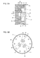
- Figs. 1A and 1B are explanatory views schematically illustrating the structure of a wave gear device produced by a method of producing according to a first embodiment of the present invention. Out of these drawings, Fig. 1A is a sectional view of the wave gear device, and Fig. 1B is a plan view of the wave gear device.
- a wave gear device 10 includes a rigid internal gear (circular spline) 20, a flex external gear (flex spline) 30, and a wave generator 40.
- the wave gear device 10 also includes a housing 50, an output member 60, a bearing 70, and a support member 80.
- the housing 50 houses the circular spline 20.
- the output member 60 serves as a flange of the flex spline 30.
- the bearing 70 uses a cross roller bearing or the like.
- the support member 80 serves as a housing of the wave generator 40.
- the housing 50 has a cylindrical main body 50A, a projection 53, and a projection 54.
- the projection 53 inwardly projects in a radial direction, which is perpendicular to the axial direction, from an inner circumferential surface 52 of the main body 50A.
- the projection 54 projects in a radial direction further inward from the inner circumferential surface 52 of the main body 50A than the projection 53.
- a step portion is formed between the projection 53 and projection 54.
- An inner surface 51 of the projection 53 is a housing reference surface (reference surface) with which a part 24A of an outer circumferential surface 24 of the circular spline 20 is brought into engagement.
- the circular spline 20 includes a gear main body 21 and a plurality of internal teeth 22.
- the gear main body 21 is formed of an annular rigid member.
- the internal teeth 22 are spaced apart from one another in the circumferential direction at an inner circumference of the gear main body 21.
- the number of internal teeth 22 of the circular spline 20 is, for example, 102.
- the circular spline 20 is secured to the inside of the housing 50 by bolts 91. Specifically, the circular spline 20 is brought into engagement with the step portion formed by the projection 53 and the projection 54.
- the part 24A of the outer circumferential surface 24 of the circular spline 20 is brought into contact with the inner circumferential surface 51 of the projection 53, and an end surface 26, which is one of two axial end surfaces 26 and 27 of the circular spline 20, is brought into contact with another part of the end surface 57 other than the part of the end surface 57.
- the end surface 57 is one of the end surfaces of the projection 54.
- the flex spline 30 includes a barrel portion 31 and an attachment portion 32.
- the barrel portion 31 is formed of a thin cylindrical material.
- the attachment portion 32 is connected to one axial end of the barrel portion 31.
- a plurality of external teeth 33 are formed on an outer circumferential surface of the barrel portion 31 at the other axial end of the barrel portion 31.
- the barrel portion 31 has flexibility.
- the flex spline 30 is a so-called cup-type flexible external gear, which has a cup shape having an opening on the side opposite to the attachment portion 32 side in the axial direction.
- the attachment portion 32 is a plate-shaped member inwardly extending in a radial direction, which is perpendicular to the axial direction, from the one axial end of the barrel portion 31.
- the attachment portion 32 of the flex spline 30 is secured to the output member 60 by bolts 94.
- the number of external teeth 33 of the flex spline 30 is less than the number of internal teeth 22 of the circular spline 20.
- the number of external teeth 33 of the flex spline 30 is 100, which is less than 102, the number of internal teeth 22 of the circular spline 20, by 2.
- a tooth trance direction of the external teeth 33 is parallel to a direction along the outer circumferential surface of the barrel portion 31 when the barrel portion 31 is not elastically deformed.
- the flex spline 30 is disposed inside the circular spline 20 such that the external teeth 33 oppose the internal teeth 22 of the circular spline 20.
- the output member 60 which is secured to the attachment portion 32 of the flex spline 30 by the bolts 94, is rotated as the flex spline 30 is rotated.
- the bearing 70 includes an inner race 71, an outer race 72, and a rolling member 73 such as a roller.
- the rolling member 73 may include, for example, balls.
- the outer race 72 is secured to the housing 50 by bolts 92, more specifically secured to the other end surface 58 of the projection 54 of the housing 50, and the inner race 71 is secured to the output member 60 by bolts 93.
- the output member 60 is rotatably supported.
- the wave generator 40 is fitted into the flex spline 30, that is, the inside of the barrel portion 31.
- the wave generator 40 is in contact with the inner circumferential surface of the barrel portion 31 at the other end of the barrel portion 31 so as to cause the barrel portion 31 to deform in the radial direction, thereby elastically deforming the barrel portion 31 into a substantially elliptical shape.
- the wave generator 40 includes a substantially elliptical cam member 41, a bearing 42, and an input shaft member 43.
- the bearing 42 is an elastically deformable thin component disposed at an outer circumference of the cam member 41.
- the input shaft member 43 is secured to the cam member 41 by bolts 95.
- the input shaft member 43 projects from both the sides of the cam member 41 in the axial direction.
- the input shaft member 43 includes a substantially disc-shaped flat plate portion, which is secured to the cam member 41, and a shaft portion, which extends from both the sides of the flat plate portion in a direction perpendicular to the flat plate portion.
- the flat plate portion is secured to the cam member 41 by the bolts 95, and the shaft portion is rotated by receiving input of an external rotational force.
- the wave generator 40 is rotatably supported by the support member 80 through a bearing 97. Specifically, one axial end of the shaft portion of the input shaft member 43 of the wave generator 40 is supported by the support member 80 through the bearing 97.
- the support member 80 is secured to the housing 50 by bolts 96.
- the other axial end of the shaft portion of the input shaft member 43 is supported by the output member 60 through a bearing 98.
- the support member 80 is secured to the housing 50 by the bolts 96.
- the support member 80 is in contact with the other end surface 27 of the circular spline 20 and secured to the projection 54 of the housing 50 by the bolts 96 with the circular spline 20 interposed therebetween.
- the outer circumferential surface 24 of the circular spline 20 and an outer circumferential surface 81 of the support member 80 are spaced apart from the inner circumferential surface of the housing 50, specifically, the inner circumferential surface 52 of the main body 50A of the housing 50. More specifically, another part 24B, which is a part of the outer circumferential surface 24 of the circular spline 20 other than the part 24A, is spaced apart from the inner circumferential surface 52 of the housing 50.
- a gap R1 serving as a first gap is formed between the housing 50 and the circular spline 20
- a gap R2 serving as a second gap is formed between the housing 50 and the support member 80.
- the wave gear device 10 is assembled in a procedure including the following steps (1) to (8):
- Step of securing circular spline 20 (first securing step: Fig. 2)
- Fig. 2 is a view for explaining the first securing step, illustrating a sectional view in a state in which the circular spline 20 is attached to the housing 50.
- the circular spline 20 is secured to the housing 50 by the bolts 91.
- the gap R1 is formed between the housing 50 and an outer circumferential surface of the circular spline 20 secured to the housing 50.
- a circular spline reference surface (reference surface) 24 is provided on the outer circumferential surface of the circular spline 20.
- the outer circumferential surface of the circular spline 20 is the reference surface 24.
- the housing reference surface (reference surface) 51 is provided on an inner circumferential surface of the housing 50.
- the housing reference surface 51 is a reference surface to position the circular spline 20 and is brought into engagement with (in contact with) part of the reference surface 24.
- an inner circumferential surface of the projection 53 of the housing 50 is the reference surface 51.
- a length L of the reference surface 51 in the axial direction is a length sufficient for positioning of the circular spline 20.
- the length L is determined by the flatness of a radially extending contact surface of the housing 50 to be in contact with the circular spline 20 and a squareness of the contact surface and the reference surface 51.
- the gap R1 relievef
- the length L of the reference surface 51 in the axial direction can be equal to or less than a half the length of the reference surface 24 in the axial direction.
- the axis of the housing 50 can be aligned with an axis A of the circular spline 20, and the reference surface 51 can be formed with high accuracy.
- components are attached with reference to the circular spline 20.
- the reference surface 51 is not necessarily formed with high accuracy or may be omitted.
- the circular spline 20 is disposed in the housing 50 with the reference surface 24 thereof disposed along the reference surface 51 and secured to the housing 50 by the bolts 91.
- the housing 50 is secured to the circular spline 20 with reference to the reference surface 24 in the present step.
- Step of positioning output member 60 (first positioning step: Figs. 3 and 4A to 4C)
- Fig. 3 is a sectional view for explaining a first positioning step and a second securing step.
- the output member 60 is positioned with a jig J1, and the output member 60 and the bearing 70 are secured.
- Figs. 4A to 4C illustrate the jig J1.
- Out of Figs. 4A to 4C, Fig. 4A is a perspective view of the jig J1
- Fig. 4B is a sectional view of jig J1
- Fig. 4C is a plan view of the jig J1.
- the jig J1 which serves as a jig for positioning the output member (first jig) illustrated in Figs. 4A to 4C , is prepared.
- the jig J1 has a reference surface P1 and a reference surface P2.
- the reference surface P1 serves as a first reference surface to be positioned with reference to the circular spline 20.
- the reference surface P2 serves as a second reference surface that positions the output member 60.
- the jig J1 has an annular portion J1 A , a shaft portion J1 B , and a connecting portion J1 c .
- the annularly shaped annular portion J1 A serves as a first annular portion.
- the shaft portion J1 B serves as a first shaft portion and is coaxial with the annular portion J1 A .
- the connecting portion J1 C connects the annular portion J1 A and the shaft portion J1 B to each other.
- An inner circumferential surface of the annular portion J1 A has the reference surface P1
- an outer circumferential surface of the shaft portion J1 B has the reference surface P2.
- the output member 60 has a reference surface 62 and a reference surface 64, which share a common axis d.
- the reference surface 62 is a side wall surface of a projection 61, which is brought into engagement with an inner circumferential surface of the bearing 70.
- the reference surface 64 is a side wall surface of a hole portion 63, which is brought into engagement with the jig J1.
- the jig J1 is formed such that the reference surface P1 and the reference surface P2 share a common axis e.
- the reference surface P1 is brought into engagement with the reference surface 24.
- the reference surface P2 is brought into engagement with the reference surface 64 of the output member 60.
- the reference surface P1 of the jig J1 and the outer circumferential surface of the circular spline 20 are brought into engagement each other by bringing the annular portion J1 A of the jig J1 into engagement with the gap R1.
- the reference surface P2 and the reference surface 64 of the hole portion 63 of the output member 60 are brought into engagement with each other by bringing the shaft portion J1 B into engagement with the hole portion 63 formed at the rotational center of the output member 60.
- the output member 60 is positioned relative to the circular spline 20 by engaging the reference surface P1 of the jig J1 with the circular spline 20 each other and engaging the reference surface P2 of the jig J1 with the output member 60.
- the axis d of the bearing 70 and the output member 60 can be aligned with the axis A of the reference surface 24 by bringing the jig J1 into engagement with the reference surface 24 of the circular spline 20 and the reference surface 64 of the output member 60, and bringing the reference surface 62 of the output member 60 into engagement with the bearing 70.
- Step of securing bearing 70 and output member 60 (second securing step: Figs. 3 and 4A to 4C)
- the output member 60 is secured to the housing 50 with the bearing 70 interposed therebetween while the output member 60 is positioned by the jig J1. That is, after the first positioning step has been performed, the outer race 72 of the bearing 70 is secured to the housing 50 by the bolts 92 and the output member 60 is secured to the inner race 71 of the bearing 70 by the bolts 93. In this step, the bearing 70 and the output member 60 are secured with reference to the reference surface 24. After the bearing 70 and the output member 60 are secured by the bolts 92 and 93, the jig J1 is removed.
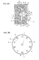
- Step of positioning flex spline 30 (second positioning step: Figs. 5A, 5B and 6A to 6C)
- Figs. 5A and 5B are views for explaining a second positioning step and a third securing step.
- the flex spline 30 is disposed in the housing 50, positioned with a jig J2, and secured.
- Fig. 5A is a sectional view of the above-described state
- Fig. 5B is a plan view of the above-described state.
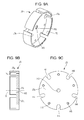
- Figs. 6A to 6C illustrate the jig J2.
- Fig. 6A is a perspective view of the jig J2
- Fig. 6B is a sectional view of jig J2
- Fig. 6C is a plan view of the jig J2.
- the jig J2 which serves as a jig for positioning the flex spline 30 (second jig) illustrated in Figs. 6A to 6C , is prepared.
- the jig J2 has a reference surface P3 and a reference surface P4.
- the reference surface P3 serves as a third reference surface to be positioned with reference to the circular spline 20.
- the reference surface P4 serves as a fourth reference surface that positions the flex spline 30.
- the jig J2 has an annular portion J2 A , a shaft portion J2 B , and a connecting portion J2 C .
- the annularly shaped annular portion J2 A serves as a second annular portion.
- the shaft portion J2 B serves as a second shaft portion and is coaxial with the annular portion J2 A .
- the connecting portion J2 C connects the annular portion J2 A and the shaft portion J2 B to each other.
- An inner circumferential surface of the annular portion J2 A has the reference surface P3
- an outer circumferential surface of the shaft portion J2 B has the reference surface P4.
- the flex spline 30 has a cup shape.
- the flex spline 30 has a hole portion 34 formed at a central portion (rotational center of attachment portion 32) thereof.
- a side wall surface of the hole portion 34 is a reference surface 35, which is a flex spline reference surface serving as a reference of the flex spline 30.
- the jig J2 is formed such that the reference surface P3 and the reference surface P4 share a common axis f.
- the reference surface P3 is brought into engagement with the reference surface 24.
- the reference surface P4 is brought into engagement with the reference surface 35.
- the jig J2 has bolt access holes H1 formed in the connecting portion J2 C thereof.
- the bolts 94 which secure the flex spline 30 to the output member 60, can be tightened through the bolt access holes H1.
- the flex spline 30 is temporarily disposed inside the circular spline 20 such that the flex spline 30 is engaged with the internal teeth 22 of the circular spline 20. Then, the jig J2 is inserted from behind (cup opening side) the flex spline 30.
- the reference surface P3 of the jig J2 and the outer circumferential surface of the circular spline 20 are brought into engagement with each other by bringing the annular portion J2 A of the jig J2 into engagement with the gap R1. Simultaneously, the reference surface P4 and the reference surface 35 of the hole portion 34 are brought into engagement with each other by bringing the shaft portion J2 B into engagement with the hole portion 34 portion 34 formed in the attachment portion 32.
- the flex spline 30 is positioned relative to the circular spline 20 by bringing the reference surface P3 of the jig J2 into engagement with the circular spline 20 and bringing the reference surface P4 of the jig J2 into engagement with the flex spline 30.
- This simultaneous engagement of the jig J2 with the reference surface 24 of the circular spline 20 and the reference surface 35 of the flex spline 30 permits an axis B of the flex spline 30 to be aligned with the axis A of the reference surface 24 of the circular spline 20.
- the gap R1 is provided in the housing 50, two positions can be simultaneously brought into engagement with each other.
- the axis B of the flex spline 30 can be aligned with the axis A of the reference surface 24.
- Step of securing flex spline 30 (third securing step: Figs. 5A, 5B, and 6A to 6C)
- the flex spline 30 is secured to the output member 60 by the bolts 94 by using the bolt access holes H1 formed in the jig J2. In this step, the flex spline 30 is secured to the output member 60 with reference to the reference surface 24.
- the connecting portion J2 C of the jig J2 has, for example, tapped holes H2.
- the jig J2 can be easily removed.
- Fig. 7 is a sectional view of a wave generator unit 100.
- the cam member 41 illustrated in Fig. 7 has a substantially elliptical outer circumferential surface and a reference surface 44 at a central portion thereof.
- the reference surface 44 which is a cylindrical inner circumferential surface of the cam member 41, serves as a reference of the cam member 41.
- the input shaft member 43 has a reference surface 45 and a reference surface 46, which share a common axis C.
- the reference surface 45 is a cylindrical outer circumferential surface brought into engagement with the reference surface 44.
- the reference surface 46 is a cylindrical outer circumferential surface brought into engagement with a jig J3 ( Figs. 9A to 9C ).
- the jig J3 serves as a jig for positioning the input shaft (third jig).
- the cam member 41 is disposed in the input shaft member 43 along the reference surface 45 of the input shaft member 43, which is secured to the cam member 41 by the bolts 95.
- An inner race of the bearing 97 is attached to the input shaft member 43, and an outer race of the bearing 97 is secured to the support member 80.
- the bearing 97 can be attached to the support member 80 so as to share the common axis C.
- a unit assembled in the present step is referred to as the wave generator unit 100.
- Step of positioning wave generator 40 (third positioning step (Figs. 8A, 8B, and 9A to 9C)
- Figs. 8A and 8B are views for explaining a third positioning step and a fourth securing step.
- the wave generator 40 is disposed in the housing 50 and positioned, and the support member 80, which supports the wave generator 40, is secured to the housing 50.
- Fig. 8A is a sectional view of the above-described state
- Fig. 8B is a plan view of the above-described state.
- Figs. 9A to 9C illustrate the jig J3.
- Fig. 9A is a perspective view of the jig J3
- Fig. 9B is a sectional view of jig J3
- Fig. 9C is a plan view of the jig J3.
- the jig J3 which serves as the jig for positioning the input member (third jig) illustrated in Figs. 9A to 9C , is prepared.
- the jig J3 has a reference surface P5 and a reference surface P6.
- the reference surface P5 serves as a fifth reference surface to be positioned with reference to the circular spline 20.
- the reference surface P6 serves as a sixth reference surface that positions the wave generator 40.
- the jig J3 has an annular portion J3 A and a planar portion J3 B .
- the annularly shaped annular portion J3 A serves as a third annular portion.
- the planar portion J3 B radially inwardly extends from the annular portion J3 A and has a through hole H3, through which the shaft portion of the input shaft member 43 is inserted.
- An inner circumferential surface of the annular portion J3 A is the reference surface P5 and a side wall surface of the through hole H3 is the reference surface P6.
- the jig J3 is formed such that the reference surface P5 and the reference surface P6 share a common axis g.
- the reference surface P5 is brought into engagement with the reference surface 24 of the circular spline 20.
- the reference surface P6 is brought into engagement with the reference surface 46 of the input shaft member 43.
- the jig J3 has bolt access holes H4, through which the bolts 96 can be tightened.
- the support member 80 is secured to the housing 50 by the bolts 96.
- the jig J3 has, for example, tapped holes H5.
- the wave generator unit 100 is temporarily disposed in the housing 50, that is, in a unit to which the flex spline 30 has been secured in the above-described third securing step, such that the wave generator 40 is disposed in the flex spline 30.
- the jig J3 is inserted from behind (support member 80 side) the wave generator unit 100 as illustrated in Fig. 8B .
- the reference surface P5 and the outer circumferential surface of the circular spline 20 are brought into engagement with each other by bringing the annular portion J3 A into engagement with the gap R1 and the gap R2, and the reference surface P6 of the through hole H3 and the reference surface 46 of the input shaft member 43 are brought into engagement with each other by inserting the shaft portion of the input shaft member 43 into the through hole H3.
- the wave generator 40 is positioned relative to the circular spline 20 by bringing the reference surface P5 and the circular spline 20 into engagement with each other and bringing the reference surface P6 and the wave generator 40 into engagement with each other.
- Step of securing wave generator 40 (fourth securing step (Figs. 8A, 8B, and 9A to 9C)
- the support member 80 supporting the wave generator 40 that is, the wave generator unit 100 is secured to the housing 50 by the bolts 96 using the bolt access holes H4 formed in the jig J3.
- the wave generator unit 100 does not interfere with the housing 50 even when the wave generator unit 100 is moved along the jig J3.
- the wave gear device 10 is completed.
- the wave generator 40 is secured with reference to the reference surface 24 of the circular spline 20.
- the flex spline 30 and the wave generator 40 are secured with reference to the reference surface 24 of the circular spline 20.
- the three main elements are positioned with reduced engaged portions. This can realize the attachment with increased accuracy. Furthermore, time required for assembling the wave gear device 10 can be reduced.
- the gap R1 is provided in the housing 50, assembly can be easily performed without interference between the housing 50 and the jigs J1 to J3.
- the length of the highly accurately processed part of the housing 50 was required to be twice that of the circular spline in the related art.
- this length of the highly accurately processed part is required to be a length equal to or less than about a half of that of the circular spline.
- the components may be positioned and secured while measuring accuracy in attachment of the components with a measuring instrument such as a dial gauge.
- a measuring instrument such as a dial gauge.
- the outer circumferential surface 24 of the circular spline 20 and the outer circumferential surface 81 of the support member 80 are spaced apart from the inner circumferential surface 52 of the housing 50, thereby the gaps R1 and R2 are formed.
- the flex spline 30 and the wave generator 40 can be positioned with reference to the circular spline 20 by using the jigs J1 to J3.
- a position/path repeatability is one of performance criteria for an articulated multi-axis robot arm (JIS B 8432: Manipulating industrial robots-Performance criteria and related test methods). In this testing, variation in motion path for a given instruction path is observed. This performance criterion significantly affects rotational accuracy of the axes. When the rotational accuracy of the axes is low, the motion path significantly varies for a single instruction path.
- Table 1 lists measured deviation amounts by which the actual motion path deviates from the shortest path between point A and point B in a movement between point A to point B, which are located within a movable range of the articulated multi-axis robot arm.
- the deviation amount is zero when the articulated multi-axis robot moves in the shortest path. That is, a smaller deviation amount means better performance.
- a measurement path 1 and a measurement path 2 are movement paths. Each of the movement paths is set between two points spaced apart from each other by 50 mm.
- the results of the performance evaluation are as listed in Table 1.
- improved results were obtained with the articulated multi-axis robot arm using the wave gear device produced by the method of producing according to the present example.
- Table 1 (unit: mm) Related-art configuration/assembly Present example configuration/assembly Coordinates of point A Coordinates of point B Measurement path 1 0.119 0.069 250 0 600 250 0 550 Measurement path 2 0.069 0.040 450 0 400 450 0 350 * Origin of coordinates: intersection of robot-arm first axis and attachment surface.
- the deviation amount is 0.119 mm with the related-art. This is decreased to 0.069 mm, or by about 40% (0.050 mm). In the measurement path 2, the deviation amount is 0.069 mm with the related-art. This is decreased to 0.040 mm, or by about 40% (0.029 mm). Thus, engagement of the components, which were not easy in the related-art, can be smoothly performed.
- the flex spline 30 and the wave generator 40 are positioned relative to the circular spline 20 with improved accuracy compared to that of the related-art, which is determined by the engagement. Accordingly, rotational accuracy of the wave gear device 10 is improved. This improves the position/path repeatability of the robot arm. Furthermore, time required for assembling the wave gear device 10 can be reduced. This reduces assembly time of the robot arm.
- the gap R1 is provided in the housing 50, assembly can be easily performed without interference between the housing 50 and the jigs J1 to J3. Furthermore, processing of the outer diameter portion of the support member 80, which was required to be highly accurate processed in the related art, becomes easy.
- the first positioning step and the second positioning step are separately performed with the different jigs J1 and J2, respectively.
- the first positioning step and the second positioning step are simultaneously performed with a common jig.
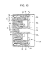
- Fig. 10 is a view for explaining the first positioning step, the second positioning step, the second securing step, and the third securing step of the method of producing the wave gear device according to the second embodiment.
- Figs. 11A to 11C illustrate a common jig. Out of Figs. 11A to 11C, Fig. 11A is a perspective view of the common jig, Fig. 11B is a sectional view of the common jig, and Fig. 11C is a plan view of the common jig. Since the structure of the wave gear device is similar to that of the first embodiment, the same reference signs denote the same elements and the description thereof is omitted.
- the jigs J1 and J2 can be integrated with each other when the following condition is satisfied: diameter of reference surface 35 of flex spline 30 ⁇ diameter of reference surface 62 of output member 60.
- a common jig JM which is formed by integrating the jigs J1 and J2 of the first embodiment with each other, is used.
- the common jig (integrated jig) JM is a jig in which the jigs J1 and J2 of the first embodiment are integrally formed.
- the common jig JM has an annular portion JM A , a shaft portion JM B , and a connecting portion JM C .
- the shaft portion JM B is coaxial with the annular portion JM A .
- the connecting portion JM C connects the annular portion JM A and the shaft portion JM B to each other.
- An inner circumferential surface of the annular portion JM A has a common reference surface P M , which serves as both the first reference surface and the third reference surface described in the first embodiment.
- An outer circumferential surface of the shaft portion JM B has the reference surface P2 serving as the second reference surface P2 and the reference surface P4 serving as the fourth reference surface, which is shifted from the reference surface P2 in the axial direction.
- the common jig JM has the bolt access holes H1 and, for example, the tapped holes H2 serving as jig removing means.
- the reference surface 24 of the circular spline 20 and the annular portion JM A are brought into engagement with each other, and then the shaft portion JM B is brought into engagement with the hole portion 63.
- the shaft portion JM B is brought into engagement with the hole portion 34 formed in the attachment portion 32 of the flex spline 30 while the common reference surface P M of the annular portion JM A and the reference surface 24 of the circular spline 20 are engaged with each other. This allows the reference surface P4 and the reference surface 35 of the hole portion 34 to be positioned.
- the output member 60 and the flex spline 30 are positioned relative to the circular spline 20.
- both of the first positioning step and the second positioning step are simultaneously performed before both of the second securing step and the third securing step is performed. That is, the first positioning step and the second positioning step are continuously performed without removing the common jig JM.
- the outer race 72 of the bearing 70 is secured to the housing 50 by the bolts 92 and the output member 60 is secured to the inner race 71 of the bearing 70 by the bolts 93 (second securing step).
- the flex spline 30 is secured to the output member 60 by the bolts 94 by using the holes H1 of the common jig JM (third securing step).
- the bearing 70, the output member 60, and the flex spline 30 can be simultaneously secured with reference to the reference surface 24 of the circular spline 20. Thus, time required for assembly can be further reduced.
- a material such as insulating material (for example, filler such as resin) or a metal material may be disposed in the gaps R1 and R2.
- the outer circumferential surface of the circular spline and the outer circumferential surface of the support member are spaced apart from the inner circumferential surface of the housing.
- the flex spline and the wave generator can be positioned with reference to the circular spline.
- a circular spline (20) is secured to a housing (50).
- An output member (60) is positioned relative to the circular spline, an outer race (72) of a bearing (70) is secured to the housing, and an inner race (71) of the bearing is secured to the output member (60).
- a flex spline (30) is positioned relative to the circular spline and secured to the output member.
- a wave generator (40) is positioned relative to the circular spline, and a support member (80), by which the wave generator is rotatably supported, is secured to the housing.
Landscapes
- Engineering & Computer Science (AREA)
- General Engineering & Computer Science (AREA)
- Mechanical Engineering (AREA)
- Retarders (AREA)
- General Details Of Gearings (AREA)
Applications Claiming Priority (1)
| Application Number | Priority Date | Filing Date | Title |
|---|---|---|---|
| JP2013218142 | 2013-10-21 |
Publications (2)
| Publication Number | Publication Date |
|---|---|
| EP2863090A2 true EP2863090A2 (de) | 2015-04-22 |
| EP2863090A3 EP2863090A3 (de) | 2016-06-01 |
Family
ID=51690932
Family Applications (1)
| Application Number | Title | Priority Date | Filing Date |
|---|---|---|---|
| EP14188749.7A Withdrawn EP2863090A3 (de) | 2013-10-21 | 2014-10-14 | Verfahren zur Herstellung einer Wellengetriebevorrichtung sowie Wellengetriebevorrichtung |
Country Status (4)
| Country | Link |
|---|---|
| US (2) | US9874272B2 (de) |
| EP (1) | EP2863090A3 (de) |
| JP (1) | JP6452370B2 (de) |
| CN (1) | CN104565281B (de) |
Families Citing this family (12)
| Publication number | Priority date | Publication date | Assignee | Title |
|---|---|---|---|---|
| US9856968B2 (en) * | 2013-11-10 | 2018-01-02 | II Thurman Tyus | Automatic transmission device |
| DE102016217055B4 (de) * | 2015-09-10 | 2023-08-24 | Schaeffler Technologies AG & Co. KG | Getriebe mit elastischem Zahnrad |
| JP6644447B2 (ja) * | 2015-12-11 | 2020-02-12 | 株式会社ハーモニック・ドライブ・システムズ | フラット型波動歯車装置 |
| JP6699213B2 (ja) * | 2016-02-12 | 2020-05-27 | 日本電産株式会社 | 電動機付き減速機 |
| CN106286763B (zh) * | 2016-10-11 | 2019-06-18 | 湖南大学 | 一种谐波减速器及其输入传动结构 |
| KR101924387B1 (ko) * | 2017-04-14 | 2018-12-03 | 주식회사 로보스타 | 2단 하모닉 드라이브 |
| CN107882949A (zh) * | 2017-10-27 | 2018-04-06 | 哈尔滨工业大学 | 一种超短设计寿命的重载单波形发生器谐波减速器 |
| CN109366477A (zh) * | 2018-11-21 | 2019-02-22 | 华中科技大学 | 一种关节机器人串联弹性驱动器 |
| JP7319822B2 (ja) * | 2019-05-10 | 2023-08-02 | ナブテスコ株式会社 | 波動歯車装置 |
| JP7793267B2 (ja) * | 2022-08-02 | 2026-01-05 | 株式会社ハーモニック・ドライブ・システムズ | 波動歯車装置 |
| CN116006654A (zh) * | 2022-12-30 | 2023-04-25 | 珠海格力电器股份有限公司 | 一种谐波减速机和机器人 |
| US12460710B2 (en) * | 2023-10-05 | 2025-11-04 | I-Hub For Robotics And Autonomous Systems Innovation Foundation | Flexible spline and wave generator for strain wave gearing |
Citations (1)
| Publication number | Priority date | Publication date | Assignee | Title |
|---|---|---|---|---|
| JP2009257409A (ja) | 2008-04-15 | 2009-11-05 | Denso Wave Inc | ハーモニック減速機の組立方法 |
Family Cites Families (14)
| Publication number | Priority date | Publication date | Assignee | Title |
|---|---|---|---|---|
| US3407902A (en) * | 1966-03-15 | 1968-10-29 | United Shoe Machinery Corp | Lubrication systems |
| EP0130763A1 (de) * | 1983-06-29 | 1985-01-09 | USM Corporation | Schutzeinrichtung für die Boden des Quetschtopfes von Spannungswellen-Getrieben |
| JPS60143245A (ja) * | 1983-12-29 | 1985-07-29 | Mitsubishi Electric Corp | ハ−モニツクギヤ装置 |
| JPS60143244A (ja) * | 1983-12-29 | 1985-07-29 | Mitsubishi Electric Corp | ハ−モニツクギヤ装置 |
| US4784015A (en) | 1987-01-23 | 1988-11-15 | Schumacher Larry L | Momentum compensated rotary actuator with harmonic drive |
| DE10010156C1 (de) | 2000-03-04 | 2001-10-31 | Oechsler Ag | Wellgetriebe und Innenrad für ein solches Getriebe |
| CN2481905Y (zh) | 2001-02-16 | 2002-03-13 | 北京中技克美谐波传动有限责任公司 | 一种带有杯形柔轮的谐波传动装置 |
| JP2002243000A (ja) * | 2001-02-19 | 2002-08-28 | Harmonic Drive Syst Ind Co Ltd | 波動歯車減速機を備えたアクチュエータ |
| CN2634199Y (zh) | 2003-09-04 | 2004-08-18 | 辛洪兵 | 一种无级变速谐波传动装置 |
| JP4646233B2 (ja) | 2006-02-28 | 2011-03-09 | 株式会社ハーモニック・ドライブ・システムズ | 波動歯車装置の入力側保持トルクの低減方法および回転アクチュエータ |
| US8384260B2 (en) * | 2009-02-03 | 2013-02-26 | Harmonic Drive Systems Inc. | Geared motor assembly |
| JP2010266008A (ja) * | 2009-05-15 | 2010-11-25 | Denso Wave Inc | ロボット用ハーモニック減速機 |
| JP5418239B2 (ja) * | 2010-01-14 | 2014-02-19 | 株式会社デンソーウェーブ | 波動歯車減速機ユニット、及び、その製造方法 |
| KR101698017B1 (ko) * | 2013-09-11 | 2017-01-19 | 가부시키가이샤 하모닉 드라이브 시스템즈 | 파동 발생기 및 파동 기어 장치 |
-
2014
- 2014-09-30 JP JP2014199758A patent/JP6452370B2/ja active Active
- 2014-10-14 EP EP14188749.7A patent/EP2863090A3/de not_active Withdrawn
- 2014-10-16 US US14/516,434 patent/US9874272B2/en not_active Expired - Fee Related
- 2014-10-21 CN CN201410559948.0A patent/CN104565281B/zh active Active
-
2017
- 2017-12-14 US US15/842,742 patent/US10760664B2/en active Active
Patent Citations (1)
| Publication number | Priority date | Publication date | Assignee | Title |
|---|---|---|---|---|
| JP2009257409A (ja) | 2008-04-15 | 2009-11-05 | Denso Wave Inc | ハーモニック減速機の組立方法 |
Also Published As
| Publication number | Publication date |
|---|---|
| US20150107388A1 (en) | 2015-04-23 |
| US20180106354A1 (en) | 2018-04-19 |
| US10760664B2 (en) | 2020-09-01 |
| US9874272B2 (en) | 2018-01-23 |
| CN104565281B (zh) | 2017-07-07 |
| JP6452370B2 (ja) | 2019-01-16 |
| JP2015108444A (ja) | 2015-06-11 |
| CN104565281A (zh) | 2015-04-29 |
| EP2863090A3 (de) | 2016-06-01 |
Similar Documents
| Publication | Publication Date | Title |
|---|---|---|
| US10760664B2 (en) | Method of producing wave gear device and wave gear device | |
| US20110265597A1 (en) | Robot arm assembly | |
| DK202170142A1 (en) | Strain wave gear with encoder integration | |
| US10427294B2 (en) | Parallel link robot and parallel link structure | |
| US11407101B2 (en) | Link actuating device | |
| US8562473B2 (en) | Speed reducer incorporating portion structure, incorporating method, and eccentric oscillating type speed reducer | |
| KR100415910B1 (ko) | 캠 장치 | |
| US12042936B2 (en) | Robot joint structure and robot with backlash reduction mechanism | |
| US9964153B2 (en) | Support device for bearing | |
| JP5418239B2 (ja) | 波動歯車減速機ユニット、及び、その製造方法 | |
| US20210079994A1 (en) | Cam device | |
| JP2025003466A (ja) | 波動歯車装置、及び、波動歯車装置の製造システム | |
| JPH0492114A (ja) | リニアモーシヨンボールベアリング及びその製造方法 | |
| US8840513B2 (en) | Speed reducer, robot hand and robot | |
| JP2017067197A (ja) | 直動装置 | |
| US20120244982A1 (en) | Speed reducer, robot hand and robot | |
| CN115523264A (zh) | 摆线针轮减速机 | |
| CN111376309B (zh) | 齿轮机构、齿轮调整方法以及机器人 | |
| CN116441907B (zh) | 一种误差修正装置 | |
| CN115523265A (zh) | 摆线针轮减速机 | |
| US11821507B2 (en) | Method of manufacturing speed reducer, speed reducer, and rotating device | |
| CN215890974U (zh) | 减速机 | |
| TW202515711A (zh) | 機械臂部件以及機器人 | |
| JP2026054756A (ja) | アクチュエータ |
Legal Events
| Date | Code | Title | Description |
|---|---|---|---|
| PUAI | Public reference made under article 153(3) epc to a published international application that has entered the european phase |
Free format text: ORIGINAL CODE: 0009012 |
|
| 17P | Request for examination filed |
Effective date: 20141014 |
|
| AK | Designated contracting states |
Kind code of ref document: A2 Designated state(s): AL AT BE BG CH CY CZ DE DK EE ES FI FR GB GR HR HU IE IS IT LI LT LU LV MC MK MT NL NO PL PT RO RS SE SI SK SM TR |
|
| AX | Request for extension of the european patent |
Extension state: BA ME |
|
| PUAL | Search report despatched |
Free format text: ORIGINAL CODE: 0009013 |
|
| AK | Designated contracting states |
Kind code of ref document: A3 Designated state(s): AL AT BE BG CH CY CZ DE DK EE ES FI FR GB GR HR HU IE IS IT LI LT LU LV MC MK MT NL NO PL PT RO RS SE SI SK SM TR |
|
| AX | Request for extension of the european patent |
Extension state: BA ME |
|
| RIC1 | Information provided on ipc code assigned before grant |
Ipc: F16H 49/00 20060101AFI20160426BHEP Ipc: F16H 57/023 20120101ALI20160426BHEP |
|
| R17P | Request for examination filed (corrected) |
Effective date: 20161201 |
|
| RBV | Designated contracting states (corrected) |
Designated state(s): AL AT BE BG CH CY CZ DE DK EE ES FI FR GB GR HR HU IE IS IT LI LT LU LV MC MK MT NL NO PL PT RO RS SE SI SK SM TR |
|
| GRAP | Despatch of communication of intention to grant a patent |
Free format text: ORIGINAL CODE: EPIDOSNIGR1 |
|
| INTG | Intention to grant announced |
Effective date: 20190924 |
|
| STAA | Information on the status of an ep patent application or granted ep patent |
Free format text: STATUS: THE APPLICATION HAS BEEN WITHDRAWN |
|
| 18W | Application withdrawn |
Effective date: 20200120 |