EP2863246B1 - Dispositif d'éclairage avec élément d'espacement et une lentille - Google Patents
Dispositif d'éclairage avec élément d'espacement et une lentille Download PDFInfo
- Publication number
- EP2863246B1 EP2863246B1 EP14195545.0A EP14195545A EP2863246B1 EP 2863246 B1 EP2863246 B1 EP 2863246B1 EP 14195545 A EP14195545 A EP 14195545A EP 2863246 B1 EP2863246 B1 EP 2863246B1
- Authority
- EP
- European Patent Office
- Prior art keywords
- lens
- lighting device
- substrate
- light emitting
- gap member
- Prior art date
- Legal status (The legal status is an assumption and is not a legal conclusion. Google has not performed a legal analysis and makes no representation as to the accuracy of the status listed.)
- Not-in-force
Links
Images












Classifications
-
- F—MECHANICAL ENGINEERING; LIGHTING; HEATING; WEAPONS; BLASTING
- F21—LIGHTING
- F21V—FUNCTIONAL FEATURES OR DETAILS OF LIGHTING DEVICES OR SYSTEMS THEREOF; STRUCTURAL COMBINATIONS OF LIGHTING DEVICES WITH OTHER ARTICLES, NOT OTHERWISE PROVIDED FOR
- F21V29/00—Protecting lighting devices from thermal damage; Cooling or heating arrangements specially adapted for lighting devices or systems
- F21V29/50—Cooling arrangements
- F21V29/502—Cooling arrangements characterised by the adaptation for cooling of specific components
- F21V29/507—Cooling arrangements characterised by the adaptation for cooling of specific components of means for protecting lighting devices from damage, e.g. housings
-
- F—MECHANICAL ENGINEERING; LIGHTING; HEATING; WEAPONS; BLASTING
- F21—LIGHTING
- F21V—FUNCTIONAL FEATURES OR DETAILS OF LIGHTING DEVICES OR SYSTEMS THEREOF; STRUCTURAL COMBINATIONS OF LIGHTING DEVICES WITH OTHER ARTICLES, NOT OTHERWISE PROVIDED FOR
- F21V5/00—Refractors for light sources
- F21V5/04—Refractors for light sources of lens shape
-
- F—MECHANICAL ENGINEERING; LIGHTING; HEATING; WEAPONS; BLASTING
- F21—LIGHTING
- F21V—FUNCTIONAL FEATURES OR DETAILS OF LIGHTING DEVICES OR SYSTEMS THEREOF; STRUCTURAL COMBINATIONS OF LIGHTING DEVICES WITH OTHER ARTICLES, NOT OTHERWISE PROVIDED FOR
- F21V15/00—Protecting lighting devices from damage
-
- F—MECHANICAL ENGINEERING; LIGHTING; HEATING; WEAPONS; BLASTING
- F21—LIGHTING
- F21V—FUNCTIONAL FEATURES OR DETAILS OF LIGHTING DEVICES OR SYSTEMS THEREOF; STRUCTURAL COMBINATIONS OF LIGHTING DEVICES WITH OTHER ARTICLES, NOT OTHERWISE PROVIDED FOR
- F21V17/00—Fastening of component parts of lighting devices, e.g. shades, globes, refractors, reflectors, filters, screens, grids or protective cages
- F21V17/10—Fastening of component parts of lighting devices, e.g. shades, globes, refractors, reflectors, filters, screens, grids or protective cages characterised by specific fastening means or way of fastening
- F21V17/12—Fastening of component parts of lighting devices, e.g. shades, globes, refractors, reflectors, filters, screens, grids or protective cages characterised by specific fastening means or way of fastening by screwing
-
- F—MECHANICAL ENGINEERING; LIGHTING; HEATING; WEAPONS; BLASTING
- F21—LIGHTING
- F21V—FUNCTIONAL FEATURES OR DETAILS OF LIGHTING DEVICES OR SYSTEMS THEREOF; STRUCTURAL COMBINATIONS OF LIGHTING DEVICES WITH OTHER ARTICLES, NOT OTHERWISE PROVIDED FOR
- F21V19/00—Fastening of light sources or lamp holders
- F21V19/001—Fastening of light sources or lamp holders the light sources being semiconductors devices, e.g. LEDs
-
- F—MECHANICAL ENGINEERING; LIGHTING; HEATING; WEAPONS; BLASTING
- F21—LIGHTING
- F21V—FUNCTIONAL FEATURES OR DETAILS OF LIGHTING DEVICES OR SYSTEMS THEREOF; STRUCTURAL COMBINATIONS OF LIGHTING DEVICES WITH OTHER ARTICLES, NOT OTHERWISE PROVIDED FOR
- F21V29/00—Protecting lighting devices from thermal damage; Cooling or heating arrangements specially adapted for lighting devices or systems
- F21V29/50—Cooling arrangements
- F21V29/70—Cooling arrangements characterised by passive heat-dissipating elements, e.g. heat-sinks
- F21V29/83—Cooling arrangements characterised by passive heat-dissipating elements, e.g. heat-sinks the elements having apertures, ducts or channels, e.g. heat radiation holes
-
- F—MECHANICAL ENGINEERING; LIGHTING; HEATING; WEAPONS; BLASTING
- F21—LIGHTING
- F21V—FUNCTIONAL FEATURES OR DETAILS OF LIGHTING DEVICES OR SYSTEMS THEREOF; STRUCTURAL COMBINATIONS OF LIGHTING DEVICES WITH OTHER ARTICLES, NOT OTHERWISE PROVIDED FOR
- F21V31/00—Gas-tight or water-tight arrangements
- F21V31/005—Sealing arrangements therefor
-
- F—MECHANICAL ENGINEERING; LIGHTING; HEATING; WEAPONS; BLASTING
- F21—LIGHTING
- F21V—FUNCTIONAL FEATURES OR DETAILS OF LIGHTING DEVICES OR SYSTEMS THEREOF; STRUCTURAL COMBINATIONS OF LIGHTING DEVICES WITH OTHER ARTICLES, NOT OTHERWISE PROVIDED FOR
- F21V5/00—Refractors for light sources
- F21V5/02—Refractors for light sources of prismatic shape
-
- F—MECHANICAL ENGINEERING; LIGHTING; HEATING; WEAPONS; BLASTING
- F21—LIGHTING
- F21V—FUNCTIONAL FEATURES OR DETAILS OF LIGHTING DEVICES OR SYSTEMS THEREOF; STRUCTURAL COMBINATIONS OF LIGHTING DEVICES WITH OTHER ARTICLES, NOT OTHERWISE PROVIDED FOR
- F21V7/00—Reflectors for light sources
-
- G—PHYSICS
- G02—OPTICS
- G02B—OPTICAL ELEMENTS, SYSTEMS OR APPARATUS
- G02B19/00—Condensers, e.g. light collectors or similar non-imaging optics
- G02B19/0004—Condensers, e.g. light collectors or similar non-imaging optics characterised by the optical means employed
- G02B19/0028—Condensers, e.g. light collectors or similar non-imaging optics characterised by the optical means employed refractive and reflective surfaces, e.g. non-imaging catadioptric systems
-
- G—PHYSICS
- G02—OPTICS
- G02B—OPTICAL ELEMENTS, SYSTEMS OR APPARATUS
- G02B19/00—Condensers, e.g. light collectors or similar non-imaging optics
- G02B19/0033—Condensers, e.g. light collectors or similar non-imaging optics characterised by the use
- G02B19/0047—Condensers, e.g. light collectors or similar non-imaging optics characterised by the use for use with a light source
- G02B19/0061—Condensers, e.g. light collectors or similar non-imaging optics characterised by the use for use with a light source the light source comprising a LED
- G02B19/0066—Condensers, e.g. light collectors or similar non-imaging optics characterised by the use for use with a light source the light source comprising a LED in the form of an LED array
-
- G—PHYSICS
- G02—OPTICS
- G02B—OPTICAL ELEMENTS, SYSTEMS OR APPARATUS
- G02B3/00—Simple or compound lenses
- G02B3/02—Simple or compound lenses with non-spherical faces
- G02B3/08—Simple or compound lenses with non-spherical faces with discontinuous faces, e.g. Fresnel lens
-
- F—MECHANICAL ENGINEERING; LIGHTING; HEATING; WEAPONS; BLASTING
- F21—LIGHTING
- F21Y—INDEXING SCHEME ASSOCIATED WITH SUBCLASSES F21K, F21L, F21S and F21V, RELATING TO THE FORM OR THE KIND OF THE LIGHT SOURCES OR OF THE COLOUR OF THE LIGHT EMITTED
- F21Y2113/00—Combination of light sources
- F21Y2113/10—Combination of light sources of different colours
- F21Y2113/13—Combination of light sources of different colours comprising an assembly of point-like light sources
-
- F—MECHANICAL ENGINEERING; LIGHTING; HEATING; WEAPONS; BLASTING
- F21—LIGHTING
- F21Y—INDEXING SCHEME ASSOCIATED WITH SUBCLASSES F21K, F21L, F21S and F21V, RELATING TO THE FORM OR THE KIND OF THE LIGHT SOURCES OR OF THE COLOUR OF THE LIGHT EMITTED
- F21Y2115/00—Light-generating elements of semiconductor light sources
- F21Y2115/10—Light-emitting diodes [LED]
-
- G—PHYSICS
- G02—OPTICS
- G02B—OPTICAL ELEMENTS, SYSTEMS OR APPARATUS
- G02B7/00—Mountings, adjusting means, or light-tight connections, for optical elements
- G02B7/02—Mountings, adjusting means, or light-tight connections, for optical elements for lenses
- G02B7/027—Mountings, adjusting means, or light-tight connections, for optical elements for lenses the lens being in the form of a sphere or ball
-
- H—ELECTRICITY
- H10—SEMICONDUCTOR DEVICES; ELECTRIC SOLID-STATE DEVICES NOT OTHERWISE PROVIDED FOR
- H10H—INORGANIC LIGHT-EMITTING SEMICONDUCTOR DEVICES HAVING POTENTIAL BARRIERS
- H10H20/00—Individual inorganic light-emitting semiconductor devices having potential barriers, e.g. light-emitting diodes [LED]
- H10H20/80—Constructional details
- H10H20/85—Packages
- H10H20/855—Optical field-shaping means, e.g. lenses
-
- H—ELECTRICITY
- H10—SEMICONDUCTOR DEVICES; ELECTRIC SOLID-STATE DEVICES NOT OTHERWISE PROVIDED FOR
- H10W—GENERIC PACKAGES, INTERCONNECTIONS, CONNECTORS OR OTHER CONSTRUCTIONAL DETAILS OF DEVICES COVERED BY CLASS H10
- H10W90/00—Package configurations
Definitions
- Lighting devices for achieve desired discharge light characteristics by additionally providing a lens to the LEDs have been proposed in the art.
- lenses for diffusing light to achieve a wide radiation surface and lenses for concentrating light having high luminance on a wide radiation surface, in lenses for lighting devices.
- CN 101 174 612 A discloses a light source and a lamp using a high power light-emitting diode.
- CN 200 986 121 Y discloses a light-emitting diode bulb structure.
- US 6 454 439 B1 discloses a method for manufacturing a light assembly from interchangeable components with different characteristics.
- An embodiment provides a lighting device, as defined in claim 1. Further embodiments are defined in claims 2-15.
- An embodiment provides a lighting device having excellent heat dissipation and waterproof characteristics.
- An embodiment provides a lighting device that can easily achieve desired discharge light distribution.
- An embodiment provides a lighting device having improved voltage resistance.
- An embodiment provides a lighting device that can be easily maintained.
- An embodiment may provide a lighting device that uses a case having excellent heat dissipation effect, and has heat dissipation characteristics by attaching a heat dissipation plate to the bottom of a light emitting unit.
- An embodiment may provide a lighting device that can easily achieve desired discharge light distribution.
- An embodiment may provide a lighting device that makes it easy to replace a lens.
- An embodiment may provide a lighting device having improved voltage resistance.
- An embodiment may provide a lighting device that is easily maintained.
- a lighting unit 100 implies the component including a lens 140, a gap member 130, and a light emitting unit 101
- the lighting unit 100 implies the component including the lens 140 and the light emitting unit 101.
- the first to fifth embodiments describe the lighting unit 100, and the others, including the sixth embodiment, describe lighting devices.
- FIG. 1 is a side view showing a lighting unit according to a first embodiment
- FIG. 2 is a side cross-sectional view of a light emitting unit of FIG. 1
- FIG. 3 is a plan view of the light emitting unit 101 of FIG. 1
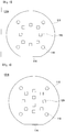
- FIG. 4 is a view showing another example of the light emitting unit 101 of FIG. 1
- FIG. 5 is a view showing another example of the light emitting unit 101 of FIG. 1
- FIG. 6 is a view showing another example of the light emitting unit of FIG. 1 .
- the substrate may be an aluminum substrate, a ceramic substrate, a metal core PCB, and a common PCB etc. Further, the substrate 110 is made of a material efficiently reflecting light, or the surface may have a color efficiently reflecting light, such as white and silver.
- the LEDs 120 include a white Led, or it is possible to selectively use color LEDs, such as a red LED, a blue LED, and a green LED.
- the light emitting angle of the LED 120 is 120° ⁇ 160°or may include a Lamertian shape (perfect diffused surface).
- the substrate 110 of the light emitting unit 101 is a circular plate having a predetermined diameter D1 and the diameter D1 may have a size that can be accommodated under the gap member 130.
- a flat portion 114 may be formed at a predetermined portion of the outer circumference of the substrate 110, in which the flat portion 114 indicates the joint between components or prevents rotation therebetween.
- a plurality of screw holes 113 may be formed in the substrate 110 to fasten the substrate 110 to structures, such as street lamps and outdoor lamps, or fasten the substrate 110 to the case of the lighting unit 110, by screwing screws into the screw holes 113. In this configuration, not only screws, but rivets or hooks may be inserted in the screw holes 113.
- the substrate 110 may not have the screw holes 113.
- the light emitting unit 101C of FIG. 5 has twelve LEDs 120 arranged on the substrate 110, and for example, an example in which eight LEDs 120 are arranged at regular intervals on a circle having a predetermined radius from the center of the substrate and four LEDs are arranged at regular intervals on a coaxial circle having a radius smaller than the above circle is shown.
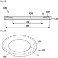
- FIG. 7 is a side cross-sectional view a gap member 130 of FIG. 1
- FIG. 8 is a perspective view of the gap member 130 of FIG. 1
- FIG. 9 is a plan view of the gap member 130 of FIG. 1
- FIG. 10 is a bottom view of the gap member 130 of FIG. 1
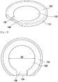
- FIG. 11 is a perspective view of another example of the gap member 130 of FIG. 1
- FIG. 12 is a plan view of another example of the gap member 130 of FIG. 1
- FIG. 13 is a bottom view of another example of the gap member 130 of FIG. 1 .
- the gap member 130 has a reflective portion 132 declined toward the center in a ring shape and a wall 131 extending down coaxially with the reflective portion 132 in a ring shape. Further, the gap member 130 has an entirely flat ring shape, such that it has an opening having a diameter that is the inner diameter of the reflective portion 132.
- the bottom of the reflective portion 132 is in contact with the edge of the upper surface of the light emitting unit 101 and the inner circumference of the wall 131 is in contact with the outer circumference of the light emitting unit 101, such that the light emitting unit 101 is seated in the gap member 130.
- the inner diameter of the reflective portion 132 is smaller than the inner diameter of the wall 131 and the outer diameter of the light emitting unit 101.
- the gap member 130 spaces the substrate 110 and the lens 140 by a predetermined gap G1. Since the gap is larger than or the same as the thickness of the LEDs 120 arranged on the substrate 110, the lens 140 dose not press the LEDs 120 and a space is defined between the lens 140 and the substrate 110, such that it is possible to achieve a light emitting angle and light distribution.
- the space 105 may be filled with silicon or silicon resin.
- the LEDs 120 of the light emitting unit 101 are exposed through the opening 133 and a flange 144 of the lens 140 is disposed on the upper surface of the gap member 130.
- the gap member 130 having the flat portion 134 is shown and the gap member 130 having the flat portion 134 is a preferred embodiment.
- the gap member 130 having an entirely circular shape without the flat portion 134 may rotate or move from the position between the parts, but except for this defect, it has all the effects of improvement of light efficiency and voltage resistance, which the gap member 130 of the embodiments described above has, and accordingly, it should be understood that not the gap member 130 having the flat portion 134 was limitatively described, but optimal embodiments were described.
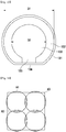
- efficiency is high when the light emitted from the lighting unit 100 makes rectangular luminance distribution as compared when it is a circle, by reducing waste of light A2 due to overlap of light and dead angel areas A3, and also reducing light A1 radiated to regions that do not need to be illuminated.
- FIG. 18 is a side cross-sectional view of a lens with an incident surface 143 of only a prism surface and a spherical exit surface 145
- FIG. 19 is a view showing spatial light distribution by a lighting unit 100 including the lens 140 of FIG. 18
- FIG. 20 is a view showing spatial light distribution by a lighting unit 100 including the lens 140 of FIG. 18 .
- the lens 140 may be formed by injection-molding a light transmissive material, and the material may be glass and plastic, such as PMMA (Poly methyl methacrylate) and PC (Polycarbonate).
- the incident surface 143 is perpendicular to the light axis, and the furrow surface 142 transverses the incident surface, preferably through the center of the incident surface 143.
- the furrow surface 141 is formed in the X-axis direction perpendicular to the light axis Z.
- the furrow surface 141 may have an arc cross section when cut along a plane (YZ-plane) perpendicular to the longitudinal direction of the furrow surface 141, or may have shapes of portions of a parabola, a hyperbola, and an ellipse.
- the furrow surface 141 has a round shape when seen from the incident surface 143, and in more detail, it has a depressed surface of a cut cylinder, when cut along a plane parallel with the longitudinal direction of the cylinder. Further, the width D4 of the furrow surface 141 may be 9% ⁇ 40% of the diameter D6 of the incident surface.
- the prism surfaces 142 are formed at both sides of the furrow surface 141.
- the prominences and depressions of the prism surface 142 extend in the axis X direction perpendicular to the light axis Z, in which the prominences and depressions are continuously arranged in the direction -Y, +Y which is perpendicular to the longitudinal direction X of the furrow surface 141 and the light axis Z.
- the prominences and depressions have a triangular cross section, when they are cut along a plane YZ perpendicular to the longitudinal direction of the furrow surface 141 of the prism surface 142. Both sides S1 and S2 of the triangular prominences may be the same or different in length and angle.
- the gap between the prominences and depressions of the prism 142 may be constant or becomes smaller toward both sides -Y-axis and +Y-axis. This density depends on the light distribution.
- Reflected light which does not travel outside through the exit surface 145, travels through the exit surface 145 while the light emitting angle changes through at least one of the prism surface 142, the reflective unit 132, and the upper surface of the substrate 110.
- the light L1 and L2 travel outside through the prism surface 142 and the exit surface 145, while the light L3 is reflected and travels outside through the exit surface 145, with the critical light angle changed sequentially through the reflective unit 132, the prism surface, the exit surface 145, and the prism surface 142.
- the light L4 emitted from the LED 120 at the center of the light emitting unit 110 is refracted and diffused through the furrow surface 141 of the lens 140 and travels outside through the exit surface 145.
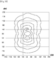
- the structures of the lens 140 with an incident surface 143 having a furrow surface 141 and the lighting unit 100 including the lens 100 was seen above, and spatial light distribution and luminance distribution are described hereafter.
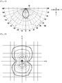
- FIG. 25 is a view showing spatial light distribution by a lighting unit 100 using the lens 140 of FIG. 21
- FIG. 26 is a view showing spatial light distribution by a lighting unit 100 using the lens 140 of FIG. 21
- B2 light distribution when the lighting unit 100 is seen from the front in the X direction
- B1 light distribution when the lighting unit 100 is seen from the front in the Y direction
- B1 The reason that B2 is wider than B1 is because light is diffused in the Y direction by the prism surface 142.
- the lens 140 has the furrow surface 141, it can be seen that spatial light distribution was improved, when seen from the X-axis and the Y-axis.
- C 2 n is a non-spherical surface constant.
- any spherical surface of non-spherical surface may be used for the shape of the exit surface 145, as long as they satisfy ⁇ Formula 1>, ⁇ Formula 2>, and ⁇ Formula 3>,
- Energy Star is an international program about energy efficiency in the United States and also a common program of DOE and EPA of the United States, and gives a mark "ENERGY STAR" to product satisfying a guide line in energy efficiency.
- Lighting devices can illuminate a desired region to illuminate with less power at predetermined luminance and the number of necessary lighting device can be reduced, such that they can be considered as high-efficiency lighting devices.
- the proposed lenses 140 are the lenses 140 that is used the lighting units 100 generally mounted in external lamps, such as street lamps and outdoor lamps; therefore, they have to satisfy Outdoor Area & Parking Garage of Category A in the standard of Energy Star.
- the computer program, FTE Calculator, is used to check whether the standard is satisfied and it is clear that those skilled in the art can easily obtain the computer program.
- the simulation data was based on Unshielded in Outdoor Area & Parking Garage of Category A in Energy Star Standard, under assumption that the lighting device has luminaire output of around 9000 lm; therefore, in this case the FTE value (lm/W) for satisfying Energy Star should be 53. Input power of 120W was measured.
- the Coverd is described in detail.
- the maximum luminance value is 30 in the radiation region where light emitted from the lighting is radiated and the minimum luminance value is 1.
- the values 30 and 1 are not absolute values, but ratios of two values.
- a region S1 where the luminance value is in the range of 1 to 30 is specified.
- a region where the luminance value is 1 is excepted, when the average luminance value in the specified region S1 is more than 6, which is six times the minimum luminance value.
- the radiation region is a region S2 where the luminance value is in the range of 1.1 to 30.
- S2 is specified as the Uniform Pool (UP). If it is more than 6.6, the above process is repeated until the average luminance value does not excess six times the minimum luminance value, and Sn is specified as the Uniform Pool (UP).
- UP Uniform Pool
- a rectangle surrounding Sn specified as described above is Rectangular Target T. Consequently, Coverd represents (UP/RT)*100.
- required FTE value, Coverd, and efficient shape may be changed in accordance with the usage, installed height, input voltage, and output intensity of light of the lighting device.
- the values used in the simulation is examples and may be measured on the basis of the Unshielded type in the FTE Calculator, and accordingly, the required FTE value may changes, such as 37, 48, and 70.
- h1 was 1mm
- h3 was 14.6mm
- D6 was 45mm in all of the experiments
- r was 24.64mm when the exit surface 145 was a spherical lens and r was 17mm when the exit surface was a non-spherical lens.
- a conic constant for a hyperbola was sued when the exit surface 145 was a non-spherical surface, and only C 4 ,C 6 , and C 8 , the non-spherical constants, were used, which is substantially meaningful to define the shape of the lens 140.
- the experiment was performed with C 4 of -9.7407e -8 , C 6 of 4.1275e -8 , and C 8 of -4.1969e -12 .
- the exit surface 145 was a spherical lens shape without the furrow surface 141, in which Coverd was 76%, FTE (lm/W) was 53, Forward and Backward of FTE (Rectangular Target) were 1.9, Sideward was 2.6, Forward and Backward of FTE (Uniform Target) was 0.9, and Sideward was 2.0.
- the exit surface 145 was a spherical lens shape with the radius of curvature of the furrow surface 141 of 5mm and the width of the furrow surface 141 of 8mm, in which Coverd was 84%, FTE (lm/W) was 58, Forward and Backward of FTE (Rectangular Target) were 1.7, Sideward was 2.6, Forward and Backward of FTE (Uniform Target) was 1.3, and Sideward was 2.1.
- the exit surface 145 was a non-spherical lens shape with the radius of curvature of the furrow surface 141 of 2mm and the width of the furrow surface 141 of 4mm, in which Coverd was 85%, FTE (lm/W) was 58, Forward and Backward of FTE (Rectangular Target) were 1.7, Sideward was 2.5, Forward and Backward of FTE (Uniform Target) was 1.3, and Sideward was 2.1.
- the exit surface 145 was a non-spherical lens shape with the radius of curvature of the furrow surface 141 of 5mm and the width of the furrow surface 141 of 8mm, in which Coverd was 88%, FTE (lm/W) was 60, Forward and Backward of FTE (Rectangular Target) were 1.6, Sideward was 2.5, Forward and Backward of FTE (Uniform Target) was 1.3, and Sideward was 2.1.
- the exit surface 145 was a non-spherical lens shape with the radius of curvature of the furrow surface 141 of 9.2mm and the width of the furrow surface 141 of 12mm, in which Coverd was 83%, FTE (lm/W) was 57, Forward and Backward of FTE (Rectangular Target) were 1.6, Sideward was 2.4, Forward and Backward of FTE (Uniform Target) was 1.2, and Sideward was 2.0.
- the exit surface 145 was a non-spherical lens shape with the radius of curvature of the furrow surface 141 of 12mm and the width of the furrow surface 141 of 16mm, in which Coverd was 89%, FTE (lm/W) was 61, Forward and Backward of FTE (Rectangular Target) were 1.4, Sideward was 2.1, Forward and Backward of FTE (Uniform Target) was 1.2, and Sideward was 1.7.
- FIG. 28 is a view showing light distribution in a space by a lighting unit 100 using the lens 140 of the experimental example 5
- FIG. 29 is a view showing light distribution in a space by a lighting unit 100 using the lens 140 of the experimental example 5.
- B2 light distribution when the lighting unit 100 is seen from the front in the X direction
- B1 light distribution when the lighting unit 100 is seen from the front in the Y direction
- B1 light distribution when the lighting unit 100 is seen from the front in the Y direction
- B1 light distribution when the lighting unit 100 is seen from the front in the Y direction
- FIG. 29 it can be seen that the luminance distribution in the Y-axis direction is considerably wider than the luminance distribution in the X-axis direction and an approximate rectangle. Comparing FIG. 28 with FIG. 25 , it can be seen that the center portion of the radiation surface is lack of light and not dark in both FIG.
- the experimental example is the most efficient in the above experimental examples.
- Sideward of FTE (Rectangular Target) is 2.5
- Sideward of FTE (Uniform Target) is 2.1, which is a high level in the experimental example
- Coverd is 88%, which is the highest level
- FTE(lm/W) is 60 which is highest level. Therefore, it will be preferable to use the lens 140 having the values of the experimental example 5.
- the factors for evaluating the efficiency of the lens 140 are various, such as the width of Sideward, Coverd, FTE (lm/W) value, as described above, and the experimental example 5 is not absolutely excellent in all of the factors. Therefore, any one of the width of Sideward, Coverd, FTE (lm/W) value may be important in real use of a lighting device, in which the lens of the other experimental examples than the experimental example 5 or the lenses 140 other than those of the experimental example 2 and the experimental example 4 to the experimental example 7 may show more excellent efficiency.
- the lighting unit 100 equipped with the lens 140 in which the exit surface 145 has a spherical or a non-spherical, the incident surface 143 has the prism surface 142 and the furrow surface 141, and the width of the furrow surface 141 is 9% ⁇ 40% of the diameter of the incident side, has higher efficiency than common lighting devices, and the lenses 140 having these features should be considered as being included in the spirit of the present invention.
- the lighting device 100 that preferably shows luminance distribution of an approximate rectangle for other usage than the street lamps and the outdoor lamps may also be equipped with the lenses 140 of the experimental examples and other equivalent lenses 140.
- FIG. 30 is a side cross-sectional view showing a lighting unit 100A according to a second embodiment.
- the first embodiment is referred for the same components as those in the first embodiment and the repeated description is omitted.
- a lighting unit 100A includes a light emitting unit 101, a lens 140, and a gap member 130.
- the gap member 130 may be made of epoxy or silicon resin in a ring shape, and is in contact with the edge of the upper surface of the substrate 110 of the light emitting unit 101 and the bottom of the flange 144 of the lens 140. Therefore, it is disposed between the substrate 110 and the lens 140 to space the substrate 110 and the lens 140 by a predetermined gap G1.
- the space3 105 defined by the gap member 130 can improve light directional distribution of the LEDs 120 of the light emitting unit 101.
- fluorescent substances may be added to the gap member, if needed.
- the upper surface of the substrate 110 of the light emitting unit 101 may be coated with a reflective substance to reflect light traveling to the substrate 110.
- FIG. 31 is a side cross-sectional view showing a lighting unit 100B according to a third embodiment.
- the first embodiment is referred for the same components as those in the first embodiment and the repeated description is omitted.
- the flange 144A which protrudes downward to the light emitting unit 101, of the lens 140 replaces the gap member 130.
- the flange 144A of the lens 140 can be disposed to contact the edge of the upper surface of the substrate 110 of the light emitting unit 101, or to contact both the outer circumference of the substrate 110 and the edge of the upper surface of the substrate 110 of the light emitting unit 101.
- the flange 144A of the lens 140 spaces the substrate 110 of the light emitting unit 101 and the lens 140 by a predetermined gap G1.
- FIG. 32 is a side cross-sectional view showing a lighting unit 100C according to a fourth embodiment.
- the first embodiment is referred for the same components as those in the first embodiment and the repeated description is omitted.
- a reflective plate 155 is disposed on the substrate 110 of the light emitting unit 101.
- the reflective plate has LED holes 155A not to cover the LEDs 120 while covers the regions where the LEDs 120 are not exposed on the substrate 110. Therefore, some of the light emitted from the LEDs 120 can be reflected from the reflective plate 155, such that the amount of reflected light increases and light efficiency is improved.
- the reflective plate 155 is not necessarily a separate member from the substrate 110 and the upper surface of the substrate 110 may replace the reflective plate 155 by increasing reflective ratio of the upper surface of the substrate 110. Further, a diffusion material may be applied to the upper surface of the reflective plate 155.
- the gap member 130 described in the first embodiment may replace the gap member 130 of the fourth embodiment, which is a fifth embodiment (not shown).
- both voltage resistance and light efficiency are improved in the same was as the effect of the gap member 130 described in the first embodiment, and the reflective plate 155 used in the fourth embodiment is used, such that the light efficiency can be more improved.
- a lighting device including the lighting unit 100 is described hereafter.
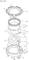
- the case body 300 and the case cover 700 are combined and fixed by screws to form the case 900 of the lighting device.
- the lens 140 makes it possible to achieve desired discharge light distribution by adjusting the light generated from the light emitting unit 101.
- the gap member 130 makes a space between the lens 140 and the light emitting unit 101 by spacing the light emitting unit and the lens 140 by a predetermined gap G1, such that it is possible to induce desired light emitting angle and light diffusion.
- the first waterproof ring 600 is disposed between the case cover 700 and the lens 400 to prevent water from flowing into the lighting device 10.
- the lighting device 10 according to the sixth embodiment, mainly the components, are described in detail.
- the case body 300 may have a circular body with a space therein, that is, an inner groove.
- the case cover 700 is shaped to correspond to the case body 300, having a circular ring shape with an opening.
- the case body 300 and the case cover 700 are combined, such that the case 900 is formed.
- the case 900 forms the body of the lighting device 10 and accommodates the heat dissipation plate 200, the light emitting unit 101, the gap member 130, the lens 140, and the first waterproof ring 600 etc.
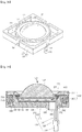
- the heat dissipation plate 200 is dispose in the space of the case body 300, that is, in the inner groove, the light emitting unit 101 is disposed on the heat dissipation plate 200, the gap member 130 is disposed on the edge of the light emitting unit 101, the lens 140 is disposed on the gap member 130, the first waterproof ring 600 is disposed on the flange 144 of the lens 140, and the case cover 700 is disposed on the first waterproof ring 600 and the case body 300. In this configuration, the lens 140 is exposed through the opening of the case cover 700.
- the shape of the case 900 that is, the shapes of the case body 300 and the case cover 700 are not limited to the circle and may be modified in various ways.
- the case 900 is preferably made of a material having good heat dissipation properties, that is, metal, for example one of aluminum (Al), nickel (Ni), copper (Cu), silver (Au), and tin (Sin). Further, the surface of the case 900 may be plated. Alternatively, the case 900 may be made of resin.
- the circumference of the case body 300 has an inner wall and an outer wall, and first hole 310, a second hole 320, and a first heat dissipation hole 330 may be formed between the inner wall and the outer wall.
- the circumference of the case cover 700 also has an inner wall and an outer wall, and a protrusion 710 and a second heat dissipation hole 730 may be formed between the inner wall and the outer wall.
- the outer walls of the circumferences of the case body 300 and the case cover 700 may not be formed where the second hole 320 is formed.
- the protrusion 710 may have a screw groove 750 and is inserted in the first hole 310, the screw 800 is inserted in the screw groove 750 and the first hole 310, such that the case body 300 and the case cover 700 can be firmly combined and fixed.
- the case 900 can be combined or separated by the screws 800, when a fault occurs in the lighting device 10, the maintenance can be easily performed by inserting or removing the screws 800.
- the heat dissipation hole 930 of the case 900 is formed by the first heat dissipation hole 330 of the case body 300 and the second heat dissipation hole 730 of the case cover 700.
- the surface area of the case 900 is increased by the heat dissipation hole 930, such that the heat generated from the light emitting unit 101 can be effectively discharged, and the weight of the lighting device can be reduce as compared with when the heat dissipation hole 930 is not formed.
- the through-hole 350 is formed such that the circumference 360 protrudes from the bottom of the case body 300. Since the circumference 360 of the through-hole 350 protrudes, the lighting device 10 can be accurately mounted to an external support member.
- the second waterproof ring 650 may be fitted around the outer circumference of the through-hole 360.
- the second waterproof ring 650 improves reliability of the lighting device 10 by prevent water from flowing into the lighting device 10 through the through-hole 350, when the lighting device 10 is attached to an external support member.
- a ring groove 660 corresponding to the shape of the second waterproof ring 650 may be formed around the outer circumference of the circumference 360 of the through-hole 350.
- the inner side 770 of the case cover 700 may be inclined and accordingly the light emitted through the lens 140 can be effectively discharged. Further, the inner side 770 of the case cover 700 fixes the heat dissipation plate 200, the light emitting unit 101, the gap member 130, the lens 140, and the first waterproof ring 600 inside the case 900.
- the light emitting unit 101 may include a substrate 110, a plurality of LEDs 120 mounted on the substrate 110, and a lead electrode 170 transmitting power to the LEDs 120.
- the light emitting unit 101 supplies light to the lighting device 10.
- the substrate is an insulating member with a circuit printed and may be an aluminum substrate, a ceramic substrate, a metal core PCB, and a common PCB etc.
- a color that efficiently reflects light for example, white may be applied to the surface of the substrate 110.
- the LEDs 120 may be mounted in an array on the substrate 110 and the arrangement and number of the LEDs 120 may be modified in various ways, if needed.
- the LEDs 120 may be light emitting diodes. As the light emitting diodes, red LEDs, blue LEDs, green LEDs, and white LEDs may be selectively used and various other arrangements can be used.
- the lead electrode 170 has one end connected to the substrate 110 and the other end exposed to the outside through the through-hole 350 formed through the bottom of the case body 300 to be electrically connected with an external power source.
- the heat dissipation plate 200 may be attached to the bottom of the light emitting unit 101.
- the heat dissipation plate 200 can discharge the heat generated from the light emitting unit 101 to the outside of the case 900.
- the heat dissipation plate 200 is made of a thermal conductive material, and for example, may be any one a thermal conductive silicon pad or a thermal conductive tape.
- the lens 140 has the exit surface 145 and the flange 144.
- the exit surface 145 adjusts discharge light distribution of the light generated from the light emitting unit 101 and discharges the light.
- the exit surface 145 is exposed through the opening of the case cover 700, such that the light can be discharged.
- the flange 144 may be formed in a circular ring shape around the bottom of the exit surface 145 and the first waterproof ring 600 is dispose on the flange 144.
- the lens 140 may be formed by injection-molding a light transmissive material, and the material may be glass and plastic, such as PMMA (Poly methyl methacrylate) and PC (Polycarbonate). Although the lens 140 is shown in a semi-spherical shape, all of the lenses 140 having various shapes described above can be used in the lighting device 10.
- the first waterproof ring 600 is disposed on the flange 144 of the lens 140.
- the first waterproof ring 600 may be formed in a circular ring shape to cover the upper surface and the circumference of the flange 144. That is, as shown in the figure, the first waterproof ring 600 may be disposed between the flange 144 of the lens 140 and the inner side 770 of the case cover 700.
- the first waterproof ring 600 may be made a waterproof material, for example, waterproof rubber or waterproof silicon.
- the second waterproof ring 650 may be disposed around the outer circumference of the circumference of the through-hole 350 formed through the bottom of the case body 300.
- the second waterproof ring 650 improves reliability of the lighting device 10 by prevent water from flowing into the lighting device 10 through the through-hole 350, when the lighting device 10 is attached to an external support member.
- the second waterproof ring 650 may be made a waterproof material, for example, waterproof rubber or waterproof silicon.
- the lighting device 10 according to the seventh embodiment mainly the components, are described in detail.
- the sixth embodiment is referred for the same components as those in the sixth embodiment and the repeated description is omitted.
- the case body 300 and the case cover 700 are combined, such that the case 900 having the rectangular shape is formed.
- the case 900 forms the body of the lighting device 10 and accommodates the heat dissipation plate 200, the light emitting unit 101, the gap member 130, the lens 140, and the first waterproof ring 600 etc.
- the case 900 can be modified in various shapes within the scope of the present invention.
- the shape of the case 900 may be a circle, a rectangle, a polygon, and an ellipse.
- the circumference of the case body 300 has an inner wall and an outer wall, and a first hole 310, a second hole (not show), and a first heat dissipation hole (not shown) may be formed between the inner wall and the outer wall.
- the protrusion 710 may have a screw hole 750 and is inserted in the first hole 310, the screw 800 is inserted in the screw hole 750 and the first hole 310, such that the case body 300 and the case cover 700 can be firmly combined and fixed.
- the screw 800 may be inserted, with the head up, into the first hole 310 of the case body 300 through the screw hole 750 of the protrusion 710 of the case cover 700. As described above, the screw 800 is exposed on the upper surface of the case cover 700 by inserting the screw 800 through the screw hole 750, such that the screw 800 can be easily inserted or removed.
- the method of combining and fixing the case cover 700 and the case body 300 is not limited to the sixth embodiment and the eighth embodiment and may be modified in various ways.
- the lighting device 10 according to the ninth embodiment, mainly the components, are described in detail.
- the sixth embodiment is referred for the same components as those in the sixth embodiment and the repeated description is omitted.
- FIG. 40 is a cross-sectional view of a lighting device according to the ninth embodiment.
- the case body 300 has a body having a space, that is, an inner groove. Further, the case cover 700 is formed in a ring shape, corresponding to the shape of the case body 300.
- a thread 320A is formed on the circumference of the case 900, instead of the second hole 320 formed to attach the lighting device 100 to a wall etc. in the sixth embodiment.
- the lighting device can be fastened to an external support member, such as a wall, a street lamp, and a vehicle, if needed, by the thread 320A.
- a threaded groove (not shown) corresponding to the thread (320A) may be formed where the lighting device is attached to an external support member, such as a wall, a street lamp, and a vehicle, such that the lighting device 10 can be attached to the external support member, such as a wall, a street lamp, and a vehicle, by fitting the thread 320A into the threaded groove (not shown).
- the lighting device 10 to the external support member, such as a wall, a street lamp, and a vehicle, without using a screw.
- the method of attaching the lighting device 10 to the external support member is not limited to the methods described in the sixth embodiment and the ninth embodiment, and may be modified in various ways.
Landscapes
- Engineering & Computer Science (AREA)
- General Engineering & Computer Science (AREA)
- Physics & Mathematics (AREA)
- General Physics & Mathematics (AREA)
- Optics & Photonics (AREA)
- Non-Portable Lighting Devices Or Systems Thereof (AREA)
- Arrangement Of Elements, Cooling, Sealing, Or The Like Of Lighting Devices (AREA)
- Securing Globes, Refractors, Reflectors Or The Like (AREA)
- Led Device Packages (AREA)
- Optical Elements Other Than Lenses (AREA)
- Lenses (AREA)
Claims (15)
- Dispositif d'éclairage comprenant :un corps de boîtier (300) ;une plaque de dissipation de chaleur (200) disposée sur le corps de boîtier ;une unité émettrice de lumière (101) disposée sur la plaque de dissipation de chaleur (200) comprenant un substrat (110) et une pluralité de DELs (120) montées sur le substrat (110) ;une lentille (140) comprenant une partie de bride (144) ;un élément d'écart (130) adapté pour assurer un écart prédéterminé entre le substrat et la lentille (140) comprenant une paroi (131) ayant une forme de bague ;une bague étanche (600) ; etun couvercle de boîtier (700) disposé sur la bague étanche (600) ;dans lequel l'unité émettrice de lumière (101) est disposée dans l'élément d'écart (130) dans lequel un diamètre (D1) de la circonférence intérieure de la paroi (131) est plus grand qu'un diamètre du substrat (110),caractérisé en ce que :la partie de bride (144) de la lentille (140) est disposée entre l'élément d'écart (130) et la bague étanche (600) ;le côté intérieur de la paroi (131) de l'élément d'écart (130) comprend une partie plane (134),le côté extérieur de substrat (110) comprend une partie plane (114) etla partie plane (114) du substrat (110) est couplée de manière à correspondre à la partie plane (134) de l'élément d'écart (130) de sorte que le substrat s'adapte dans l'élément d'écart.
- Dispositif d'éclairage de la revendication 1, dans lequel la partie plane (134) de l'élément d'écart (130) est en partie disposée sur un côté extérieur de la paroi (131).
- Dispositif d'éclairage la revendication 1 ou 2, dans lequel l'unité émettrice de lumière (101) comprend en outre un électrode conductrice (170) ou un fil électrique transmettant de l'énergie vers le dispositif émetteur de lumière (120), et dans lequel la paroi (131) de l'élément d'écart (130) comprend une partie de passage d'électrode (135) à travers laquelle l'électrode conductrice (170) ou le fil électrique passe.
- Dispositif d'éclairage d'une quelconque des revendications 1 à 3, dans lequel l'élément d'écart (130) comprend une partie réfléchissante (132) ayant une ouverture (133) et étant étendue à une inclinaison prédéterminée depuis une face supérieure de la paroi (131) vers le centre de l'ouverture (133), et dans lequel les DELs (120) sont exposées à travers l'ouverture (133).
- Dispositif d'éclairage de la revendication 4, dans lequel une face inférieure de la partie réfléchissante (132) est en contact avec un bord d'une face supérieure du substrat (110), et dans lequel la circonférence intérieure de la paroi (131) est en contact avec une circonférence extérieure du substrat (110).
- Dispositif d'éclairage de la revendication 4 ou 5, dans lequel un diamètre intérieur (D2) de la partie réfléchissante (132) est plus petit que le diamètre (D1) de la paroi (131).
- Dispositif d'éclairage de la revendication 3, dans lequel le diamètre du substrat est plus petit qu'un diamètre de la plaque de dissipation de chaleur (200).
- Dispositif d'éclairage d'une quelconque des revendications 1 à 7, dans lequel l'unité émettrice de lumière (101) comprend en outre une plaque réfléchissante (155) disposée sur le substrat (110).
- Dispositif d'éclairage d'une quelconque des revendications 1 à 8, dans lequel le corps de boîtier (300) a un corps circulaire avec un espace accueillant la plaque de dissipation de chaleur (200), l'unité émettrice de lumière (101), l'élément d'écart (130) et la lentille (140), et dans lequel le corps de boîtier (300) et le couvercle de boîtier (70) sont combinés et fixés par des vis.
- Dispositif d'éclairage la revendication 9, dans lequel le couvercle de boîtier (700) est disposé sur le corps de boîtier (300) et a une forme de bague circulaire avec une ouverture, dans lequel la lentille (140) comprend une face de sortie sphérique (145) et une bride (144) disposés autour d'un fond de la face de sortie (145), et
dans lequel la face de sortie (145) de la lentille (140) est disposée dans l'ouverture du couvercle de boîtier (700). - Dispositif d'éclairage de la revendication 9 ou 10, dans lequel le corps de boîtier (300) a un premier trou de dissipation de chaleur (330), dans lequel le couvercle de boîtier (700) a un deuxième trou de dissipation de chaleur (730), et dans lequel le premier trou de dissipation de chaleur (330) et le deuxième trou de dissipation de chaleur (730) forment un trou de dissipation de chaleur (930).
- Dispositif d'éclairage d'une quelconque des revendications 9 à 11, dans lequel le couvercle de boîtier (1700) comprend un côté intérieur (770) étendu à une première inclinaison prédéterminée depuis une face supérieure du couvercle de boîtier (700) vers le centre de l'ouverture du couvercle de boîtier (700).
- Dispositif d'éclairage de la revendication 12, dans lequel la bague étanche (600) est disposée entre le côté intérieur (1670) du couvercle de boîtier (700) et la bride (144) de la lentille (140).
- Dispositif d'éclairage de la revendication 13, dans lequel la bague étanche (600) recouvre une face supérieure et une circonférence de la bride (144).
- Dispositif d'éclairage d'une quelconque des revendications 9 à 14, dans lequel le corps de boîtier (300) comprend un fil (320A) disposé sur une circonférence du corps de boîtier (300).
Applications Claiming Priority (6)
| Application Number | Priority Date | Filing Date | Title |
|---|---|---|---|
| KR1020090045342A KR101028201B1 (ko) | 2009-05-25 | 2009-05-25 | 렌즈 및 이를 구비한 조명 유닛 |
| KR1020090049987A KR101007134B1 (ko) | 2009-06-05 | 2009-06-05 | 조명 장치 |
| KR1020100032961A KR101113611B1 (ko) | 2010-04-09 | 2010-04-09 | 조명 유닛용 렌즈 |
| KR1020100033043A KR101610317B1 (ko) | 2010-04-10 | 2010-04-10 | 조명 유닛용 갭부재를 포함하는 조명 장치 |
| EP13183276.8A EP2672299B1 (fr) | 2009-05-25 | 2010-05-25 | Espaceur, lentille et dispositif d'éclairage l'utilisant |
| EP10163837.7A EP2287640B1 (fr) | 2009-05-25 | 2010-05-25 | Espaceur, lentille et dispositif d'éclairage l'utilisant |
Related Parent Applications (3)
| Application Number | Title | Priority Date | Filing Date |
|---|---|---|---|
| EP10163837.7A Division EP2287640B1 (fr) | 2009-05-25 | 2010-05-25 | Espaceur, lentille et dispositif d'éclairage l'utilisant |
| EP13183276.8A Division EP2672299B1 (fr) | 2009-05-25 | 2010-05-25 | Espaceur, lentille et dispositif d'éclairage l'utilisant |
| EP13183276.8A Division-Into EP2672299B1 (fr) | 2009-05-25 | 2010-05-25 | Espaceur, lentille et dispositif d'éclairage l'utilisant |
Publications (3)
| Publication Number | Publication Date |
|---|---|
| EP2863246A1 EP2863246A1 (fr) | 2015-04-22 |
| EP2863246B1 true EP2863246B1 (fr) | 2017-04-26 |
| EP2863246B8 EP2863246B8 (fr) | 2017-07-12 |
Family
ID=43368980
Family Applications (3)
| Application Number | Title | Priority Date | Filing Date |
|---|---|---|---|
| EP10163837.7A Not-in-force EP2287640B1 (fr) | 2009-05-25 | 2010-05-25 | Espaceur, lentille et dispositif d'éclairage l'utilisant |
| EP13183276.8A Not-in-force EP2672299B1 (fr) | 2009-05-25 | 2010-05-25 | Espaceur, lentille et dispositif d'éclairage l'utilisant |
| EP14195545.0A Not-in-force EP2863246B8 (fr) | 2009-05-25 | 2010-05-25 | Dispositif d'éclairage avec élément d'espacement et une lentille |
Family Applications Before (2)
| Application Number | Title | Priority Date | Filing Date |
|---|---|---|---|
| EP10163837.7A Not-in-force EP2287640B1 (fr) | 2009-05-25 | 2010-05-25 | Espaceur, lentille et dispositif d'éclairage l'utilisant |
| EP13183276.8A Not-in-force EP2672299B1 (fr) | 2009-05-25 | 2010-05-25 | Espaceur, lentille et dispositif d'éclairage l'utilisant |
Country Status (3)
| Country | Link |
|---|---|
| EP (3) | EP2287640B1 (fr) |
| JP (2) | JP5634129B2 (fr) |
| CN (2) | CN101929651B (fr) |
Families Citing this family (50)
| Publication number | Priority date | Publication date | Assignee | Title |
|---|---|---|---|---|
| JP2012133964A (ja) * | 2010-12-21 | 2012-07-12 | Panasonic Corp | Ledユニットおよびそれを用いた照明器具 |
| CN102121678B (zh) * | 2011-01-15 | 2012-12-12 | 珠海晟源同泰电子有限公司 | Led灯具配光模块的设计方法 |
| DE102011000735B4 (de) * | 2011-02-15 | 2016-02-25 | Hella Kgaa Hueck & Co. | Wärmeausdehnungskompensator und Scheinwerfer |
| JP5573746B2 (ja) * | 2011-03-23 | 2014-08-20 | 豊田合成株式会社 | ランプユニット |
| CN102287679A (zh) * | 2011-05-26 | 2011-12-21 | 深圳市华星光电技术有限公司 | 光源模块以及背光模块 |
| KR101814808B1 (ko) * | 2011-07-18 | 2018-01-04 | 엘지이노텍 주식회사 | 광학 부재, 이를 포함하는 표시장치 및 이의 제조방법 |
| CN102252267A (zh) * | 2011-07-26 | 2011-11-23 | 青岛海信电器股份有限公司 | 透镜、led光源装置和led背光模组 |
| JP5879876B2 (ja) * | 2011-09-28 | 2016-03-08 | スタンレー電気株式会社 | 車両用灯具ユニット |
| KR101962121B1 (ko) * | 2011-12-12 | 2019-03-28 | 삼성디스플레이 주식회사 | 렌즈, 및 이를 포함하는 백라이트 어셈블리 및 표시 장치 |
| JP6338533B2 (ja) * | 2011-12-22 | 2018-06-06 | ヘプタゴン・マイクロ・オプティクス・プライベート・リミテッドHeptagon Micro Optics Pte. Ltd. | 光電子モジュール、特にフラッシュモジュールおよびそれらの製造方法 |
| CN103185289B (zh) * | 2011-12-29 | 2016-08-03 | 海洋王照明科技股份有限公司 | 一种光束调整透镜及包括该透镜的照明装置 |
| KR101262051B1 (ko) * | 2012-02-13 | 2013-05-08 | 엘지이노텍 주식회사 | 발광소자 패키지 |
| CN102854201A (zh) * | 2012-09-18 | 2013-01-02 | 上海创波光电科技有限公司 | 一种胶囊表面检测装置 |
| JP2014067646A (ja) * | 2012-09-26 | 2014-04-17 | Gs Yuasa Corp | 照明装置 |
| CN104048193B (zh) * | 2013-03-14 | 2016-12-28 | 深圳市邦贝尔电子有限公司 | Led灯珠 |
| CN104048262A (zh) * | 2013-03-15 | 2014-09-17 | 欧司朗有限公司 | 透镜和照明装置 |
| CN104141889A (zh) * | 2013-05-08 | 2014-11-12 | 欧普照明电器(中山)有限公司 | 一种照明灯具 |
| JP5868897B2 (ja) * | 2013-05-31 | 2016-02-24 | 株式会社アイ・ライティング・システム | 照明器具 |
| US9995475B2 (en) | 2013-05-31 | 2018-06-12 | Iwasaki Electric Co., Ltd. | Illumination device |
| JP6243162B2 (ja) * | 2013-08-05 | 2017-12-06 | スリーエム イノベイティブ プロパティズ カンパニー | 発光素子モジュール |
| CN104373894A (zh) * | 2013-08-16 | 2015-02-25 | 鸿富锦精密工业(深圳)有限公司 | 透镜组及使用该透镜组的光源装置 |
| EP2857744A1 (fr) * | 2013-10-07 | 2015-04-08 | Hella KGaA Hueck & Co | Module à LED et système d'éclairage |
| US10036538B2 (en) | 2013-11-20 | 2018-07-31 | Philips Lighting Holding B.V. | Method and apparatus for uniform illumination of a surface |
| DE102013021309A1 (de) * | 2013-12-19 | 2015-06-25 | Erco Gmbh | Leuchte u.a. |
| US9810403B2 (en) * | 2014-02-12 | 2017-11-07 | Philips Lighting Holding B.V. | Lighting device and luminaire |
| KR102219489B1 (ko) * | 2014-05-14 | 2021-02-24 | 엘지이노텍 주식회사 | 발광 소자 패키지 |
| KR102221598B1 (ko) | 2014-06-16 | 2021-03-02 | 엘지이노텍 주식회사 | 발광 소자 패키지 |
| KR102305234B1 (ko) * | 2015-01-28 | 2021-09-29 | 쑤저우 레킨 세미컨덕터 컴퍼니 리미티드 | 광원 유닛 |
| WO2016146047A1 (fr) * | 2015-03-13 | 2016-09-22 | 杭州华普永明光电股份有限公司 | Module de del et dispositif d'éclairage |
| CN105135922A (zh) * | 2015-08-28 | 2015-12-09 | 中山市绿涛电子科技有限公司 | 一种散热器 |
| CN105226172B (zh) * | 2015-09-08 | 2017-07-14 | 李峰 | 防水封装结构及其一体成型处理工艺 |
| CN105526554A (zh) * | 2016-01-06 | 2016-04-27 | 苏州立杰机电有限公司 | Led装饰灯和照明方法 |
| CN105526528A (zh) * | 2016-01-06 | 2016-04-27 | 苏州立杰机电有限公司 | 装饰用led照明灯 |
| US12268788B2 (en) | 2016-05-24 | 2025-04-08 | Signify Holding, B.V. | UV module within consumer machines |
| JP6793936B2 (ja) * | 2016-08-02 | 2020-12-02 | 嶋田プレシジョン株式会社 | 照射装置 |
| JP6920675B2 (ja) * | 2017-03-09 | 2021-08-18 | パナソニックIpマネジメント株式会社 | 照明装置 |
| US10468566B2 (en) * | 2017-04-10 | 2019-11-05 | Ideal Industries Lighting Llc | Hybrid lens for controlled light distribution |
| JP2018181726A (ja) * | 2017-04-19 | 2018-11-15 | 株式会社エンプラス | 光束制御部材、発光装置、面光源装置および表示装置 |
| ES2931474T3 (es) | 2017-08-25 | 2022-12-29 | Cree Huizhou Solid State Lighting Co Ltd | Paquete integrado de fuentes de luz LED múltiples |
| CN107976726A (zh) * | 2017-11-13 | 2018-05-01 | 成都依菲兰科技有限公司 | 一种光效可调节的柱状透镜 |
| CN109780497A (zh) * | 2017-11-14 | 2019-05-21 | 江苏亿诺车辆部件有限公司 | 汽车led光源透镜 |
| ES2801381T3 (es) * | 2017-12-04 | 2021-01-11 | Zkw Group Gmbh | Faro de vehículo y procedimiento para el ajuste de una fuente de luz y de una óptica auxiliar |
| JP2018129314A (ja) * | 2018-05-25 | 2018-08-16 | 株式会社ニコン | 照明装置 |
| KR102642878B1 (ko) * | 2018-06-11 | 2024-03-05 | 서울바이오시스 주식회사 | 발광 다이오드 패키지 및 발광 다이오드 패키지를 포함하는 광 조사 장치 |
| CN111665604B (zh) * | 2019-03-05 | 2022-09-06 | 微软技术许可有限责任公司 | 透镜系统及成像装置 |
| WO2020223485A1 (fr) * | 2019-05-01 | 2020-11-05 | Lumileds Llc | Élément optique dépoli de façon sélective pour une mise en forme de faisceau |
| US10677419B1 (en) | 2019-05-01 | 2020-06-09 | Lumileds Holding B.V. | Selectively frosted optical element for beam shaping |
| CN110617454A (zh) * | 2019-10-18 | 2019-12-27 | 清华大学深圳国际研究生院 | 一种车辆前照灯 |
| CN116249934A (zh) | 2020-10-02 | 2023-06-09 | 日亚化学工业株式会社 | 光源装置和导光阵列部 |
| KR20240124760A (ko) * | 2023-02-09 | 2024-08-19 | 삼성전기주식회사 | 렌즈 조립체 |
Family Cites Families (23)
| Publication number | Priority date | Publication date | Assignee | Title |
|---|---|---|---|---|
| US4991073A (en) * | 1989-03-08 | 1991-02-05 | Gte Products Corporation | Lighting lens |
| US5806955A (en) * | 1992-04-16 | 1998-09-15 | Tir Technologies, Inc. | TIR lens for waveguide injection |
| JP3393993B2 (ja) * | 1998-04-15 | 2003-04-07 | タイコエレクトロニクスアンプ株式会社 | 電気コネクタ |
| US6454439B1 (en) * | 2000-06-16 | 2002-09-24 | Itc Incorporated | Method for manufacturing a light assembly from interchangeable components with different characteristics |
| CN2600712Y (zh) * | 2002-12-31 | 2004-01-21 | 浙江天台天宇灯饰有限公司 | 防水安全灯座 |
| JP2005019110A (ja) * | 2003-06-24 | 2005-01-20 | Matsushita Electric Works Ltd | 埋込灯 |
| KR200377622Y1 (ko) * | 2004-12-21 | 2005-03-14 | 김봉수 | 방열형 발광다이오드 투광등 시스템 |
| KR100496522B1 (ko) * | 2005-03-23 | 2005-06-27 | 주식회사 누리플랜 | 엘이디 조명등 |
| JP2007073478A (ja) * | 2005-09-09 | 2007-03-22 | Toshiba Lighting & Technology Corp | ランプ |
| JP4789673B2 (ja) * | 2005-10-27 | 2011-10-12 | 京セラ株式会社 | 発光素子収納用パッケージならびにこれを用いた光源および発光装置 |
| SE0600675L (sv) * | 2006-03-24 | 2007-02-20 | Prismalence Ab | Belysningsarmatur med ett täckglas vilket innefattar parallella uppskjutande kammar |
| US7906794B2 (en) * | 2006-07-05 | 2011-03-15 | Koninklijke Philips Electronics N.V. | Light emitting device package with frame and optically transmissive element |
| WO2008053753A1 (fr) * | 2006-10-31 | 2008-05-08 | Techno Polymer Co., Ltd. | Composition de résine dissipatrice de chaleur, substrat pour montage de led, réflecteur, et substrat pour montage de led comportant une partie réflecteur |
| CN101174612A (zh) * | 2006-10-31 | 2008-05-07 | 宁波安迪光电科技有限公司 | 大功率发光二极管光源装置及具有该光源装置的灯具 |
| JP4552928B2 (ja) * | 2006-11-22 | 2010-09-29 | ウシオ電機株式会社 | 放電ランプ保持機構 |
| CN200986121Y (zh) * | 2006-12-04 | 2007-12-05 | 品能科技股份有限公司 | 发光二极管灯泡结构 |
| US7686486B2 (en) * | 2007-06-30 | 2010-03-30 | Osram Sylvania Inc. | LED lamp module |
| US20100284191A1 (en) * | 2007-09-17 | 2010-11-11 | Imc Est. | Lighting body |
| JP4962253B2 (ja) * | 2007-10-09 | 2012-06-27 | 日亜化学工業株式会社 | Led電球 |
| JP5150235B2 (ja) * | 2007-12-14 | 2013-02-20 | スタンレー電気株式会社 | ダイレクトプロジェクター型灯具の投影レンズ |
| CN101373063A (zh) * | 2008-09-05 | 2009-02-25 | 汕尾市大利荣耀灯饰工业有限公司 | 一种长寿节能led射灯的散热装置 |
| JP3147238U (ja) * | 2008-10-09 | 2008-12-18 | 靄▲威▼科技股▲分▼有限公司 | 工作機械用のled照明装置 |
| JP5477590B2 (ja) * | 2010-07-16 | 2014-04-23 | 東芝ライテック株式会社 | ランプ装置および照明装置 |
-
2010
- 2010-05-25 EP EP10163837.7A patent/EP2287640B1/fr not_active Not-in-force
- 2010-05-25 JP JP2010119382A patent/JP5634129B2/ja not_active Expired - Fee Related
- 2010-05-25 CN CN201010192728.0A patent/CN101929651B/zh active Active
- 2010-05-25 EP EP13183276.8A patent/EP2672299B1/fr not_active Not-in-force
- 2010-05-25 CN CN201610444002.9A patent/CN106122896B/zh active Active
- 2010-05-25 EP EP14195545.0A patent/EP2863246B8/fr not_active Not-in-force
-
2014
- 2014-10-14 JP JP2014209991A patent/JP5976749B2/ja not_active Expired - Fee Related
Non-Patent Citations (1)
| Title |
|---|
| None * |
Also Published As
| Publication number | Publication date |
|---|---|
| EP2672299A1 (fr) | 2013-12-11 |
| CN106122896B (zh) | 2019-12-20 |
| EP2863246B8 (fr) | 2017-07-12 |
| CN101929651B (zh) | 2016-08-03 |
| JP5634129B2 (ja) | 2014-12-03 |
| JP2015053270A (ja) | 2015-03-19 |
| JP2010272527A (ja) | 2010-12-02 |
| EP2287640A3 (fr) | 2012-02-15 |
| EP2863246A1 (fr) | 2015-04-22 |
| EP2672299B1 (fr) | 2015-01-07 |
| JP5976749B2 (ja) | 2016-08-24 |
| EP2287640A2 (fr) | 2011-02-23 |
| EP2287640B1 (fr) | 2014-08-20 |
| CN101929651A (zh) | 2010-12-29 |
| CN106122896A (zh) | 2016-11-16 |
Similar Documents
| Publication | Publication Date | Title |
|---|---|---|
| EP2863246B1 (fr) | Dispositif d'éclairage avec élément d'espacement et une lentille | |
| US8313218B2 (en) | Gap member, lens and lighting device having the same | |
| JP6637574B2 (ja) | 照明装置 | |
| CA2729669C (fr) | Tube fluorescent de rechange equipe de del orientees dans le sens longitudinal | |
| US6502956B1 (en) | Light emitting diode lamp with individual LED lenses | |
| US9163794B2 (en) | Power supply assembly for LED-based light tube | |
| KR101047439B1 (ko) | 렌즈 및 렌즈를 포함하는 조명 유닛 | |
| US20110305024A1 (en) | Led tube lamp | |
| US20160003417A1 (en) | Flat lighting device | |
| US20100207131A1 (en) | Light emitting device | |
| US9605830B1 (en) | Systems, methods and devices for an LED lighting module with a light transmissive cover | |
| CN107631271B (zh) | 一种透镜、光源模组、光源模组组合和照明装置 | |
| WO2017092624A1 (fr) | Élément optique, module d'éclairage et moyen d'éclairage doté du module d'éclairage | |
| KR101147322B1 (ko) | 반도체 발광장치, 반도체 발광모듈 및 조명장치 | |
| US20140369037A1 (en) | Omnidirectional Lamp | |
| US8772802B2 (en) | Light emitting device with transparent plate | |
| CN221301229U (zh) | 一种led灯 | |
| KR101113611B1 (ko) | 조명 유닛용 렌즈 | |
| KR101610317B1 (ko) | 조명 유닛용 갭부재를 포함하는 조명 장치 | |
| KR101557443B1 (ko) | 조명기기 | |
| KR20240164593A (ko) | 저탄소를 위한 에너지 저감 과 조광조색 제어가 가능한 저전력 스마트 도로 조명등 모듈장치. | |
| KR101694997B1 (ko) | 조명 유닛용 렌즈 | |
| CN206803061U (zh) | 一种光源模组及照明装置 | |
| KR101730142B1 (ko) | 조명 유닛용 렌즈 | |
| CN219389482U (zh) | 照明装置 |
Legal Events
| Date | Code | Title | Description |
|---|---|---|---|
| PUAI | Public reference made under article 153(3) epc to a published international application that has entered the european phase |
Free format text: ORIGINAL CODE: 0009012 |
|
| 17P | Request for examination filed |
Effective date: 20141128 |
|
| AC | Divisional application: reference to earlier application |
Ref document number: 2287640 Country of ref document: EP Kind code of ref document: P Ref document number: 2672299 Country of ref document: EP Kind code of ref document: P |
|
| AK | Designated contracting states |
Kind code of ref document: A1 Designated state(s): AL AT BE BG CH CY CZ DE DK EE ES FI FR GB GR HR HU IE IS IT LI LT LU LV MC MK MT NL NO PL PT RO SE SI SK SM TR |
|
| R17P | Request for examination filed (corrected) |
Effective date: 20151020 |
|
| RBV | Designated contracting states (corrected) |
Designated state(s): AL AT BE BG CH CY CZ DE DK EE ES FI FR GB GR HR HU IE IS IT LI LT LU LV MC MK MT NL NO PL PT RO SE SI SK SM TR |
|
| 17Q | First examination report despatched |
Effective date: 20160224 |
|
| GRAP | Despatch of communication of intention to grant a patent |
Free format text: ORIGINAL CODE: EPIDOSNIGR1 |
|
| STAA | Information on the status of an ep patent application or granted ep patent |
Free format text: STATUS: GRANT OF PATENT IS INTENDED |
|
| RIC1 | Information provided on ipc code assigned before grant |
Ipc: F21Y 115/10 20160101ALI20161031BHEP Ipc: F21V 17/12 20060101ALI20161031BHEP Ipc: F21V 5/02 20060101ALI20161031BHEP Ipc: F21V 29/00 20150101ALI20161031BHEP Ipc: G02B 17/08 20060101ALI20161031BHEP Ipc: G02B 19/00 20060101ALI20161031BHEP Ipc: H01L 25/075 20060101ALI20161031BHEP Ipc: F21V 31/00 20060101ALI20161031BHEP Ipc: F21S 8/10 20060101ALI20161031BHEP Ipc: F21Y 113/13 20160101ALI20161031BHEP Ipc: F21Y 101/00 20160101ALI20161031BHEP Ipc: F21V 29/507 20150101ALI20161031BHEP Ipc: G02B 7/02 20060101ALI20161031BHEP Ipc: F21V 29/83 20150101ALI20161031BHEP Ipc: F21V 9/00 20150101ALI20161031BHEP Ipc: H01L 33/58 20100101ALI20161031BHEP Ipc: G02B 3/08 20060101AFI20161031BHEP |
|
| INTG | Intention to grant announced |
Effective date: 20161118 |
|
| GRAS | Grant fee paid |
Free format text: ORIGINAL CODE: EPIDOSNIGR3 |
|
| GRAA | (expected) grant |
Free format text: ORIGINAL CODE: 0009210 |
|
| STAA | Information on the status of an ep patent application or granted ep patent |
Free format text: STATUS: THE PATENT HAS BEEN GRANTED |
|
| AC | Divisional application: reference to earlier application |
Ref document number: 2672299 Country of ref document: EP Kind code of ref document: P Ref document number: 2287640 Country of ref document: EP Kind code of ref document: P |
|
| AK | Designated contracting states |
Kind code of ref document: B1 Designated state(s): AL AT BE BG CH CY CZ DE DK EE ES FI FR GB GR HR HU IE IS IT LI LT LU LV MC MK MT NL NO PL PT RO SE SI SK SM TR |
|
| REG | Reference to a national code |
Ref country code: GB Ref legal event code: FG4D |
|
| REG | Reference to a national code |
Ref country code: CH Ref legal event code: EP |
|
| REG | Reference to a national code |
Ref country code: AT Ref legal event code: REF Ref document number: 888362 Country of ref document: AT Kind code of ref document: T Effective date: 20170515 |
|
| RAP2 | Party data changed (patent owner data changed or rights of a patent transferred) |
Owner name: LG INNOTEK CO., LTD. |
|
| REG | Reference to a national code |
Ref country code: IE Ref legal event code: FG4D |
|
| REG | Reference to a national code |
Ref country code: FR Ref legal event code: PLFP Year of fee payment: 8 |
|
| REG | Reference to a national code |
Ref country code: NL Ref legal event code: FP |
|
| REG | Reference to a national code |
Ref country code: DE Ref legal event code: R096 Ref document number: 602010041949 Country of ref document: DE |
|
| REG | Reference to a national code |
Ref country code: LT Ref legal event code: MG4D |
|
| REG | Reference to a national code |
Ref country code: AT Ref legal event code: MK05 Ref document number: 888362 Country of ref document: AT Kind code of ref document: T Effective date: 20170426 |
|
| PG25 | Lapsed in a contracting state [announced via postgrant information from national office to epo] |
Ref country code: NO Free format text: LAPSE BECAUSE OF FAILURE TO SUBMIT A TRANSLATION OF THE DESCRIPTION OR TO PAY THE FEE WITHIN THE PRESCRIBED TIME-LIMIT Effective date: 20170726 Ref country code: HR Free format text: LAPSE BECAUSE OF FAILURE TO SUBMIT A TRANSLATION OF THE DESCRIPTION OR TO PAY THE FEE WITHIN THE PRESCRIBED TIME-LIMIT Effective date: 20170426 Ref country code: FI Free format text: LAPSE BECAUSE OF FAILURE TO SUBMIT A TRANSLATION OF THE DESCRIPTION OR TO PAY THE FEE WITHIN THE PRESCRIBED TIME-LIMIT Effective date: 20170426 Ref country code: ES Free format text: LAPSE BECAUSE OF FAILURE TO SUBMIT A TRANSLATION OF THE DESCRIPTION OR TO PAY THE FEE WITHIN THE PRESCRIBED TIME-LIMIT Effective date: 20170426 Ref country code: LT Free format text: LAPSE BECAUSE OF FAILURE TO SUBMIT A TRANSLATION OF THE DESCRIPTION OR TO PAY THE FEE WITHIN THE PRESCRIBED TIME-LIMIT Effective date: 20170426 Ref country code: GR Free format text: LAPSE BECAUSE OF FAILURE TO SUBMIT A TRANSLATION OF THE DESCRIPTION OR TO PAY THE FEE WITHIN THE PRESCRIBED TIME-LIMIT Effective date: 20170727 Ref country code: AT Free format text: LAPSE BECAUSE OF FAILURE TO SUBMIT A TRANSLATION OF THE DESCRIPTION OR TO PAY THE FEE WITHIN THE PRESCRIBED TIME-LIMIT Effective date: 20170426 |
|
| PG25 | Lapsed in a contracting state [announced via postgrant information from national office to epo] |
Ref country code: PL Free format text: LAPSE BECAUSE OF FAILURE TO SUBMIT A TRANSLATION OF THE DESCRIPTION OR TO PAY THE FEE WITHIN THE PRESCRIBED TIME-LIMIT Effective date: 20170426 Ref country code: BG Free format text: LAPSE BECAUSE OF FAILURE TO SUBMIT A TRANSLATION OF THE DESCRIPTION OR TO PAY THE FEE WITHIN THE PRESCRIBED TIME-LIMIT Effective date: 20170726 Ref country code: IS Free format text: LAPSE BECAUSE OF FAILURE TO SUBMIT A TRANSLATION OF THE DESCRIPTION OR TO PAY THE FEE WITHIN THE PRESCRIBED TIME-LIMIT Effective date: 20170826 Ref country code: SE Free format text: LAPSE BECAUSE OF FAILURE TO SUBMIT A TRANSLATION OF THE DESCRIPTION OR TO PAY THE FEE WITHIN THE PRESCRIBED TIME-LIMIT Effective date: 20170426 Ref country code: LV Free format text: LAPSE BECAUSE OF FAILURE TO SUBMIT A TRANSLATION OF THE DESCRIPTION OR TO PAY THE FEE WITHIN THE PRESCRIBED TIME-LIMIT Effective date: 20170426 |
|
| REG | Reference to a national code |
Ref country code: CH Ref legal event code: PL |
|
| REG | Reference to a national code |
Ref country code: DE Ref legal event code: R097 Ref document number: 602010041949 Country of ref document: DE |
|
| PG25 | Lapsed in a contracting state [announced via postgrant information from national office to epo] |
Ref country code: SK Free format text: LAPSE BECAUSE OF FAILURE TO SUBMIT A TRANSLATION OF THE DESCRIPTION OR TO PAY THE FEE WITHIN THE PRESCRIBED TIME-LIMIT Effective date: 20170426 Ref country code: DK Free format text: LAPSE BECAUSE OF FAILURE TO SUBMIT A TRANSLATION OF THE DESCRIPTION OR TO PAY THE FEE WITHIN THE PRESCRIBED TIME-LIMIT Effective date: 20170426 Ref country code: RO Free format text: LAPSE BECAUSE OF FAILURE TO SUBMIT A TRANSLATION OF THE DESCRIPTION OR TO PAY THE FEE WITHIN THE PRESCRIBED TIME-LIMIT Effective date: 20170426 Ref country code: MC Free format text: LAPSE BECAUSE OF FAILURE TO SUBMIT A TRANSLATION OF THE DESCRIPTION OR TO PAY THE FEE WITHIN THE PRESCRIBED TIME-LIMIT Effective date: 20170426 Ref country code: EE Free format text: LAPSE BECAUSE OF FAILURE TO SUBMIT A TRANSLATION OF THE DESCRIPTION OR TO PAY THE FEE WITHIN THE PRESCRIBED TIME-LIMIT Effective date: 20170426 Ref country code: CZ Free format text: LAPSE BECAUSE OF FAILURE TO SUBMIT A TRANSLATION OF THE DESCRIPTION OR TO PAY THE FEE WITHIN THE PRESCRIBED TIME-LIMIT Effective date: 20170426 |
|
| REG | Reference to a national code |
Ref country code: IE Ref legal event code: MM4A |
|
| PG25 | Lapsed in a contracting state [announced via postgrant information from national office to epo] |
Ref country code: CH Free format text: LAPSE BECAUSE OF NON-PAYMENT OF DUE FEES Effective date: 20170531 Ref country code: IT Free format text: LAPSE BECAUSE OF FAILURE TO SUBMIT A TRANSLATION OF THE DESCRIPTION OR TO PAY THE FEE WITHIN THE PRESCRIBED TIME-LIMIT Effective date: 20170426 Ref country code: LI Free format text: LAPSE BECAUSE OF NON-PAYMENT OF DUE FEES Effective date: 20170531 Ref country code: SM Free format text: LAPSE BECAUSE OF FAILURE TO SUBMIT A TRANSLATION OF THE DESCRIPTION OR TO PAY THE FEE WITHIN THE PRESCRIBED TIME-LIMIT Effective date: 20170426 |
|
| PLBE | No opposition filed within time limit |
Free format text: ORIGINAL CODE: 0009261 |
|
| STAA | Information on the status of an ep patent application or granted ep patent |
Free format text: STATUS: NO OPPOSITION FILED WITHIN TIME LIMIT |
|
| PG25 | Lapsed in a contracting state [announced via postgrant information from national office to epo] |
Ref country code: LU Free format text: LAPSE BECAUSE OF NON-PAYMENT OF DUE FEES Effective date: 20170525 |
|
| 26N | No opposition filed |
Effective date: 20180129 |
|
| REG | Reference to a national code |
Ref country code: FR Ref legal event code: PLFP Year of fee payment: 9 |
|
| REG | Reference to a national code |
Ref country code: BE Ref legal event code: MM Effective date: 20170531 |
|
| PG25 | Lapsed in a contracting state [announced via postgrant information from national office to epo] |
Ref country code: IE Free format text: LAPSE BECAUSE OF NON-PAYMENT OF DUE FEES Effective date: 20170525 |
|
| PG25 | Lapsed in a contracting state [announced via postgrant information from national office to epo] |
Ref country code: SI Free format text: LAPSE BECAUSE OF FAILURE TO SUBMIT A TRANSLATION OF THE DESCRIPTION OR TO PAY THE FEE WITHIN THE PRESCRIBED TIME-LIMIT Effective date: 20170426 |
|
| PG25 | Lapsed in a contracting state [announced via postgrant information from national office to epo] |
Ref country code: BE Free format text: LAPSE BECAUSE OF NON-PAYMENT OF DUE FEES Effective date: 20170531 |
|
| PG25 | Lapsed in a contracting state [announced via postgrant information from national office to epo] |
Ref country code: MT Free format text: LAPSE BECAUSE OF NON-PAYMENT OF DUE FEES Effective date: 20170525 |
|
| PG25 | Lapsed in a contracting state [announced via postgrant information from national office to epo] |
Ref country code: HU Free format text: LAPSE BECAUSE OF FAILURE TO SUBMIT A TRANSLATION OF THE DESCRIPTION OR TO PAY THE FEE WITHIN THE PRESCRIBED TIME-LIMIT; INVALID AB INITIO Effective date: 20100525 |
|
| PG25 | Lapsed in a contracting state [announced via postgrant information from national office to epo] |
Ref country code: CY Free format text: LAPSE BECAUSE OF FAILURE TO SUBMIT A TRANSLATION OF THE DESCRIPTION OR TO PAY THE FEE WITHIN THE PRESCRIBED TIME-LIMIT Effective date: 20170426 |
|
| PG25 | Lapsed in a contracting state [announced via postgrant information from national office to epo] |
Ref country code: MK Free format text: LAPSE BECAUSE OF FAILURE TO SUBMIT A TRANSLATION OF THE DESCRIPTION OR TO PAY THE FEE WITHIN THE PRESCRIBED TIME-LIMIT Effective date: 20170426 |
|
| PG25 | Lapsed in a contracting state [announced via postgrant information from national office to epo] |
Ref country code: TR Free format text: LAPSE BECAUSE OF FAILURE TO SUBMIT A TRANSLATION OF THE DESCRIPTION OR TO PAY THE FEE WITHIN THE PRESCRIBED TIME-LIMIT Effective date: 20170426 |
|
| PG25 | Lapsed in a contracting state [announced via postgrant information from national office to epo] |
Ref country code: PT Free format text: LAPSE BECAUSE OF FAILURE TO SUBMIT A TRANSLATION OF THE DESCRIPTION OR TO PAY THE FEE WITHIN THE PRESCRIBED TIME-LIMIT Effective date: 20170426 |
|
| PG25 | Lapsed in a contracting state [announced via postgrant information from national office to epo] |
Ref country code: AL Free format text: LAPSE BECAUSE OF FAILURE TO SUBMIT A TRANSLATION OF THE DESCRIPTION OR TO PAY THE FEE WITHIN THE PRESCRIBED TIME-LIMIT Effective date: 20170426 |
|
| REG | Reference to a national code |
Ref country code: GB Ref legal event code: 732E Free format text: REGISTERED BETWEEN 20210722 AND 20210728 Ref country code: NL Ref legal event code: PD Owner name: SUZHOU LEKIN SEMICONDUCTOR CO., LTD.; CN Free format text: DETAILS ASSIGNMENT: CHANGE OF OWNER(S), ASSIGNMENT; FORMER OWNER NAME: LG INNOTEK CO., LTD. Effective date: 20210719 |
|
| REG | Reference to a national code |
Ref country code: DE Ref legal event code: R081 Ref document number: 602010041949 Country of ref document: DE Owner name: SUZHOU LEKIN SEMICONDUCTOR CO. LTD., TAICANG, CN Free format text: FORMER OWNER: LG INNOTEK CO., LTD., SEOUL, KR |
|
| REG | Reference to a national code |
Ref country code: FR Ref legal event code: PLFP Year of fee payment: 14 |
|
| PGFP | Annual fee paid to national office [announced via postgrant information from national office to epo] |
Ref country code: NL Payment date: 20230417 Year of fee payment: 14 |
|
| PGFP | Annual fee paid to national office [announced via postgrant information from national office to epo] |
Ref country code: FR Payment date: 20230411 Year of fee payment: 14 Ref country code: DE Payment date: 20230404 Year of fee payment: 14 |
|
| PGFP | Annual fee paid to national office [announced via postgrant information from national office to epo] |
Ref country code: GB Payment date: 20230406 Year of fee payment: 14 |
|
| REG | Reference to a national code |
Ref country code: DE Ref legal event code: R119 Ref document number: 602010041949 Country of ref document: DE |
|
| REG | Reference to a national code |
Ref country code: NL Ref legal event code: MM Effective date: 20240601 |
|
| GBPC | Gb: european patent ceased through non-payment of renewal fee |
Effective date: 20240525 |
|
| PG25 | Lapsed in a contracting state [announced via postgrant information from national office to epo] |
Ref country code: NL Free format text: LAPSE BECAUSE OF NON-PAYMENT OF DUE FEES Effective date: 20240601 |
|
| PG25 | Lapsed in a contracting state [announced via postgrant information from national office to epo] |
Ref country code: DE Free format text: LAPSE BECAUSE OF NON-PAYMENT OF DUE FEES Effective date: 20241203 |
|
| PG25 | Lapsed in a contracting state [announced via postgrant information from national office to epo] |
Ref country code: FR Free format text: LAPSE BECAUSE OF NON-PAYMENT OF DUE FEES Effective date: 20240531 |
|
| PG25 | Lapsed in a contracting state [announced via postgrant information from national office to epo] |
Ref country code: GB Free format text: LAPSE BECAUSE OF NON-PAYMENT OF DUE FEES Effective date: 20240525 |