EP2863634A1 - Bildverarbeitungsvorrichtung und system zur anzeige dreidimensionaler bilder - Google Patents
Bildverarbeitungsvorrichtung und system zur anzeige dreidimensionaler bilder Download PDFInfo
- Publication number
- EP2863634A1 EP2863634A1 EP13803595.1A EP13803595A EP2863634A1 EP 2863634 A1 EP2863634 A1 EP 2863634A1 EP 13803595 A EP13803595 A EP 13803595A EP 2863634 A1 EP2863634 A1 EP 2863634A1
- Authority
- EP
- European Patent Office
- Prior art keywords
- indication
- auxiliary
- image
- parallax
- attention
- Prior art date
- Legal status (The legal status is an assumption and is not a legal conclusion. Google has not performed a legal analysis and makes no representation as to the accuracy of the status listed.)
- Ceased
Links
Images


Classifications
-
- H—ELECTRICITY
- H04—ELECTRIC COMMUNICATION TECHNIQUE
- H04N—PICTORIAL COMMUNICATION, e.g. TELEVISION
- H04N13/00—Stereoscopic video systems; Multi-view video systems; Details thereof
- H04N13/30—Image reproducers
- H04N13/366—Image reproducers using viewer tracking
- H04N13/383—Image reproducers using viewer tracking for tracking with gaze detection, i.e. detecting the lines of sight of the viewer's eyes
-
- A—HUMAN NECESSITIES
- A61—MEDICAL OR VETERINARY SCIENCE; HYGIENE
- A61B—DIAGNOSIS; SURGERY; IDENTIFICATION
- A61B1/00—Instruments for performing medical examinations of the interior of cavities or tubes of the body by visual or photographical inspection, e.g. endoscopes; Illuminating arrangements therefor
- A61B1/00002—Operational features of endoscopes
- A61B1/00004—Operational features of endoscopes characterised by electronic signal processing
- A61B1/00009—Operational features of endoscopes characterised by electronic signal processing of image signals during a use of endoscope
-
- A—HUMAN NECESSITIES
- A61—MEDICAL OR VETERINARY SCIENCE; HYGIENE
- A61B—DIAGNOSIS; SURGERY; IDENTIFICATION
- A61B1/00—Instruments for performing medical examinations of the interior of cavities or tubes of the body by visual or photographical inspection, e.g. endoscopes; Illuminating arrangements therefor
- A61B1/00163—Optical arrangements
- A61B1/00194—Optical arrangements adapted for three-dimensional imaging
-
- H—ELECTRICITY
- H04—ELECTRIC COMMUNICATION TECHNIQUE
- H04N—PICTORIAL COMMUNICATION, e.g. TELEVISION
- H04N13/00—Stereoscopic video systems; Multi-view video systems; Details thereof
- H04N13/10—Processing, recording or transmission of stereoscopic or multi-view image signals
- H04N13/106—Processing image signals
- H04N13/128—Adjusting depth or disparity
-
- H—ELECTRICITY
- H04—ELECTRIC COMMUNICATION TECHNIQUE
- H04N—PICTORIAL COMMUNICATION, e.g. TELEVISION
- H04N13/00—Stereoscopic video systems; Multi-view video systems; Details thereof
- H04N13/10—Processing, recording or transmission of stereoscopic or multi-view image signals
- H04N13/106—Processing image signals
- H04N13/156—Mixing image signals
-
- H—ELECTRICITY
- H04—ELECTRIC COMMUNICATION TECHNIQUE
- H04N—PICTORIAL COMMUNICATION, e.g. TELEVISION
- H04N13/00—Stereoscopic video systems; Multi-view video systems; Details thereof
- H04N13/10—Processing, recording or transmission of stereoscopic or multi-view image signals
- H04N13/106—Processing image signals
- H04N13/172—Processing image signals image signals comprising non-image signal components, e.g. headers or format information
- H04N13/183—On-screen display [OSD] information, e.g. subtitles or menus
-
- H—ELECTRICITY
- H04—ELECTRIC COMMUNICATION TECHNIQUE
- H04N—PICTORIAL COMMUNICATION, e.g. TELEVISION
- H04N13/00—Stereoscopic video systems; Multi-view video systems; Details thereof
- H04N13/30—Image reproducers
- H04N13/361—Reproducing mixed stereoscopic images; Reproducing mixed monoscopic and stereoscopic images, e.g. a stereoscopic image overlay window on a monoscopic image background
-
- A—HUMAN NECESSITIES
- A61—MEDICAL OR VETERINARY SCIENCE; HYGIENE
- A61B—DIAGNOSIS; SURGERY; IDENTIFICATION
- A61B1/00—Instruments for performing medical examinations of the interior of cavities or tubes of the body by visual or photographical inspection, e.g. endoscopes; Illuminating arrangements therefor
- A61B1/00163—Optical arrangements
- A61B1/00193—Optical arrangements adapted for stereoscopic vision
Definitions
- the present invention relates to an image-processing device and a three-dimensional-image observation system.
- Patent Literature 1 there are known devices that allow an observer to view a three-dimensional image of an imaging subject by using a pair of parallax images obtained by acquiring images of the imaging subject from two points of view that correspond to the left and right eyes (for example, see Patent Literature 1).
- the device disclosed in Patent Literature 1 is provided with a function for displaying graphic objects such as letters, figures, symbols, and so forth that are added to the three-dimensional image by the observer in a superimposed manner at the same depthwise position as the imaging subject in the three-dimensional image.
- Patent Literature 1 When moving his/her attention point between different depthwise positions in the three-dimensional image, the observer needs to change the angle of convergence formed by lines of sight of the left and right eyes. This adjustment of the angle of convergence causes eye fatigue in the observer. In the case of Patent Literature 1, the angle of convergence is changed every time the attention point is moved between the graphic objects and the imaging subject. Therefore, the device disclosed in Patent Literature 1 is not suitable for use in cases where an imaging subject is observed by performing visual comparison between an auxiliary indication, such as a graphic object, and an imaging subject by frequently moving the attention point back-and-forth therebetween.
- an auxiliary indication such as a graphic object
- the present invention has been conceived in light of the above-described circumstances, and an object thereof is to provide an image-processing device and a three-dimensional-image observation system with which it is possible to reduce eye fatigue in an observer even in the case in which observation is performed by performing visual comparison between an imaging subject and an auxiliary indication by using a three-dimensional image of the imaging subject and the auxiliary indication superimposed on the imaging subject.
- the present invention provides the following solutions.
- a first aspect of the present invention is an image-processing device including a display portion that displays a three-dimensional image of an imaging subject reproduced from two parallax images obtained by acquiring images of the imaging subject; an attention-point detecting portion that detects an attention point of an observer viewing the three-dimensional image displayed on the display portion; a parallax calculating portion that calculates parallax between the two parallax images at the attention point detected by the attention-point detecting portion; and an auxiliary-indication creating portion that creates an auxiliary indication including information about the imaging subject, that superimposes the created auxiliary indication on the three-dimensional image, and that displays the superimposed image on the display portion, wherein the auxiliary-indication creating portion creates the auxiliary indication to which, based on parallax calculated by the parallax calculating portion, the same parallax as the calculated parallax is assigned.
- the auxiliary indication created by the auxiliary-indication creating portion is displayed on the display portion in a state in which the auxiliary indication is superimposed on the imaging subject. Therefore, the observer can perform observation by performing visual comparison between the imaging subject and the auxiliary indication in the same three-dimensional image.
- the attention point of the observer in the three-dimensional image displayed on the display portion is detected by the attention-point detecting portion, and the parallax of the imaging subject between the two parallax images at the attention point is calculated by the parallax calculating portion.
- the auxiliary indication having the same parallax as the parallax at the attention point is created by the auxiliary-indication creating portion and is displayed by being superimposed on the three-dimensional image of the imaging subject.
- the auxiliary indication is displayed in the three-dimensional image at the same depthwise position as the attention point that the observer is currently viewing. Therefore, it is possible to reduce the eye fatigue in the observer even when performing observation by performing visual comparison between the imaging subject and the auxiliary indication.
- the attention-point detecting portion may be provided with a line-of-sight detecting portion that detects lines of sight of left and right eyes of the observer and an attention-point calculating portion that calculates an intersection of the two lines of sight detected by the line-of-sight detecting portion as the attention point.
- the attention-point detecting portion may detect a target object that the observer observes by using the two parallax images, for example, an instrument for treating a biological object, which serves as the imaging subject, or an affected region that exists in the biological object, and the position of the detected target object may be used as the attention point.
- the attention-point detecting portion may store a reference image obtained by acquiring the target object, and may detect the target object in the parallax images by comparing the reference image with the parallax images.
- the auxiliary-indication creating portion may display the auxiliary indication at a position at which the auxiliary indication does not overlap with the attention point detected by the attention-point detecting portion in a direction parallel to the plane of the parallax image.
- the auxiliary-indication creating portion may set a plurality of predetermined regions as candidates at which to display the auxiliary indication with respect to a display region in the three-dimensional image on the display portion, may select a region having a lower parallax than the parallax at the attention point from the plurality of candidates, and may display the auxiliary indication at the selected region.
- priority ranks may be assigned to the plurality of candidates, and the auxiliary-indication creating portion may select a region having the highest priority rank among regions having lower parallax than the parallax at the attention point.
- the auxiliary-indication creating portion may create, as an auxiliary indication, an indication showing a measured value of biometric information of the biological object that serves as the imaging subject, may also set at least two degrees of urgency in accordance with the magnitude of the measured value of the biometric information, may create the auxiliary indication in a normal indication form when the measured value corresponds to the lower degree of urgency, and may create the auxiliary indication in an indication form having a greater emphasis than the normal indication form when the measured value corresponds to the higher degree of urgency.
- the auxiliary-indication creating portion may change the indication form to the normal indication form when the auxiliary indication matches the attention point detected by the attention-point detecting portion.
- the auxiliary-indication creating portion may create, as the auxiliary indication, a local-information indication including information about a specific position in the imaging subject, may display the auxiliary indication on the display portion, and may move the auxiliary indication in the direction of the plane based on a track of the attention point obtained by the attention-point detecting portion.
- the auxiliary indication is also moved to follow the target object. Therefore, it is possible to easily make the observer recognize the correspondence relationship between the target object and the auxiliary indication.
- the attention-point detecting portion may obtain a track of the attention point by storing the position of the detected attention point over time
- the auxiliary-indication creating portion may create, as the auxiliary indication, a local-information indication including information about a specific position in the imaging subject and an arrow that points to the specific position from the local-information indication, may assign the same parallax as a parallax at the attention point to the local-information indication and a base of the arrow, and may assign the same parallax as a parallax at the specific position to a tip of the arrow.
- a second aspect of the present invention is a three-dimensional-image observation system including an image-acquisition device that obtains two parallax images by acquiring images of an imaging subject; and any one of image-processing device described above.
- a third aspect of the present invention is a three-dimensional-image observation system including an image-acquisition device that obtains two parallax images by acquiring images of an imaging subject; and an image-processing device described above, wherein the image-acquisition device obtains, as the parallax images, a normal image acquired by irradiating the imaging subject with illumination light and a fluorescence image obtained by acquiring, by irradiating the imaging subject with excitation light, fluorescence from a fluorescent substance provided in the target object, and the attention-point detecting portion detects, as the target object, a fluorescence region in the fluorescence image.
- an advantage is afforded in that it is possible to reduce eye fatigue in an observer even in the case in which observation is performed by performing visual comparison between an imaging subject and an auxiliary indication by using a three-dimensional image of the imaging subject and the auxiliary indication superimposed on the imaging subject.
- a three-dimensional-image observation system 100 according to an embodiment of the present invention will be described below with reference to the drawings.
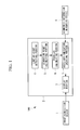
- the three-dimensional-image observation system 100 is provided with an image-acquisition device 1 that acquires an image of an imaging subject and an image-processing device 2 that reproduces and displays a three-dimensional image of the imaging subject based on two two-dimensional images of the imaging subject obtained by the image-acquisition device 1.
- the image-acquisition device 1 is, for example, an endoscope (hereinafter, also referred to as the endoscope 1) for observing, as the imaging subject, tissue inside the body of a subject, and has two objective lenses (not shown) that correspond to the right eye and the left eye of an observer.
- Two two-dimensional images acquired by the image-acquisition device 1 by using the two objective lenses are parallax images in which the imaging subject is observed from different points of view. This pair of parallax images constitute parallax images needed to reproduce a three-dimensional image of the imaging subject.
- the pair of parallax images may be created by using a pupil-division system instead of creating the pair of parallax images by using the two objective lenses.
- the image-acquisition device 1 may be provided with a single objective lens that forms an optical image of the imaging subject and a pupil-division portion, such as a prism, that divides the optical image of the imaging subject formed by the objective lens into left and right parts centered on the optical axis, and a pair of parallax images may be obtained by individually acquiring the two optical images divided by the pupil-division portion.
- the image-processing device 2 is provided with a display portion 3 that receives the parallax images from the image-acquisition device 1 and displays the parallax images as a three-dimensional image; a line-of-sight detecting portion (attention-point detecting portion) 4 that detects the lines of sight of the left and right eyes of the observer viewing the display portion 3; an attention-point calculating portion (attention-point detecting portion) 5 that calculates an attention point at which the left and right lines of sight detected by the line-of-sight detecting portion 4 intersect each other; a parallax calculating portion 6 that calculates the parallax of the parallax images at the attention point detected by the attention-point calculating portion 5; and an auxiliary-indication creating portion 7 that creates an auxiliary indication based on information about the imaging subject, that superimposes the auxiliary indication on the three-dimensional image of the imaging subject, and that displays the superimposed image on the display portion 3.
- a line-of-sight detecting portion (attention-point detecting
- the line-of-sight detecting portion 4 detects positions of the left and right eyeballs of the observer facing the display portion 3 and calculates the left and right lines of sight of the observer based on the detected eyeball positions.
- a means of detecting the eyeball positions for example, a camera that is provided in the display portion 3 and that acquires images of the left and right eyeballs of the observer is employed.
- the eyeball positions may be detected by using means other than a camera.
- the attention-point calculating portion 5 calculates a position at which the left and right lines of sight of the observer detected by the line-of-sight detecting portion 4 intersect each other.
- the parallax calculating portion 6 calculates the parallax between the left and right parallax images at the attention point calculated by the attention-point calculating portion 5.
- the auxiliary-indication creating portion 7 receives measured values from a biometric-information measuring device 8 that measures biometric information (for example, heart rate, blood pressure, and body temperature) of the subject, and creates an auxiliary indication that shows the received measured values. Then, the auxiliary-indication creating portion 7 creates left and right auxiliary-indication parallax images that display the auxiliary indications. At this time, the auxiliary-indication creating portion 7 sets the parallax between the auxiliary indication in the right auxiliary-indication parallax image and the auxiliary indication in the left auxiliary-indication parallax image so as to be equal to the parallax calculated by the parallax calculating portion 6. The auxiliary-indication creating portion 7 outputs the created left and right auxiliary-indication parallax images to the display portion 3.
- biometric information for example, heart rate, blood pressure, and body temperature
- the auxiliary-indication creating portion 7 may create other indications showing other details as auxiliary indications 9.
- the image-processing device 2 may create a letter sequence, a grid, and a scale that shows the size of the imaging subject, which are arbitrarily input by the observer, an image of the imaging subject acquired from another angle by another image-acquisition device, an image that serves as a diagnostic reference, and so forth and may display them on the display portion 3.
- the display portion 3 individually superimposes the left and right auxiliary-indication parallax images received from the auxiliary-indication creating portion 7 on the left and right parallax images received from the image-acquisition device 1 and constructs a three-dimensional image by using the superimposed parallax images.
- tissue inside the body of a subject is observed by using the endoscope 1 that serves as the image-acquisition device, and the obtained images are displayed to the observer in the form of a three-dimensional image.
- the endoscope 1 obtains a pair of parallax images with different points of view by acquiring images of the tissue inside the body of the subject at the same time by using the left and right objective lenses.
- the obtained pair of parallax images are successively transmitted to the image-processing device 2 and are converted to a three-dimensional image which is subsequently displayed on the display portion 3.
- the biometric information of the subject is measured by the biometric-information measuring device 8, and the measured values thereof are transmitted to the image-processing device 2.
- the image-processing device 2 creates auxiliary indications showing the measured values of the individual pieces of biometric information received from the biometric-information measuring device 8, and displays these auxiliary indications superimposed on the three-dimensional image of the tissue inside the body. By doing so, the observer can check the tissue inside the body of the subject and the measured values of the biometric information on the same three-dimensional image.
- the image-processing device 2 displays the auxiliary indication 9 at a position at which the parallax thereof would be equal to the parallax at the attention point O.
- lines of sight L1 and L2 of the observer who is observing the three-dimensional image displayed on the display portion 3 are detected by the line-of-sight detecting portion 4, and the position of the attention point O to which the observer is currently paying attention is calculated by the attention-point calculating portion 5 based on the detected lines of sight L1 and L2.
- the parallax between the left and right parallax images at the attention point O is calculated by the parallax calculating portion 6, and the auxiliary-indication creating portion 7 creates auxiliary-indication parallax images in which the auxiliary indication 9 is displayed at the position at which the parallax thereof is equal to the calculated parallax.
- the display portion 3 superimposes the right auxiliary-indication parallax image on the right parallax image, superimposes the left auxiliary-indication parallax image on the left parallax image, and constructs a three-dimensional image by using the left and right superimposed parallax images.
- the auxiliary indication 9 is displayed at the same depthwise position as that of the attention point O to which the observer is currently paying attention.
- reference signs A and B indicate instruments operated by the observer
- reference sign X indicates tissue inside the body
- reference sign Y indicates an affected region.
- the attention point O is detected based on the lines of sight L1 and L2 of the observer, and the auxiliary indication 9 is displayed at the same depthwise position as this attention point O. Therefore, the observer can view the auxiliary indication 9 by moving the lines of sight L1 and L2 from the attention point O without changing the angle of convergence. Accordingly, there is an advantage in that eye fatigue can be reduced even in the case in which the tissue X or affected region Y is observed while visually checking the auxiliary indication 9 frequently.
- the auxiliary indication 9 may be allowed to move so as to follow the attention point O only when the attention point O of the observer remains at substantially the same position for a certain amount of time. By doing so, the auxiliary indication 9 is prevented from moving more than necessary, thus reducing the irritation experienced by the observer.
- the parallax calculating portion 6 stores the parallax calculated at the attention point O over time, starts a clock when the parallax changes due to a movement of the attention point O, and, in the case in which a predetermined amount of time has passed, newly outputs the parallax at the moved attention point O to the auxiliary-indication creating portion 7.
- the auxiliary-indication creating portion 7 stores the parallax received from the parallax calculating portion 6, and continues to create the auxiliary-indication parallax images by using the stored parallax.
- the auxiliary-indication creating portion 7 updates the stored parallax to the new parallax, and creates the auxiliary-indication parallax images by using this new parallax. Accordingly, the depthwise position of the auxiliary indication 9 displayed on the three-dimensional image is changed when the attention point O of the observer remains at substantially the same position for a certain amount of time.
- the parallax calculating portion 6 may calculate an average parallax at the attention point O within a predetermined window of time, and may output the calculated average parallax to the auxiliary-indication creating portion 7.
- the auxiliary indication 9 is made less sensitive to following the fine movement of the attention point O of the observer, and the auxiliary indication 9 is kept sufficiently sensitive to following coarse movement of the attention point O of the observer. In this way also, the auxiliary indication 9 can be prevented from moving more than necessary, thus eliminating the irritation experienced by the observer.
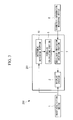
- a three-dimensional-image observation system 200 is configured so that an image-processing device 201 uses instruments (target objects) A and B in images obtained by the image-acquisition device 1 as the attention point O of the observer.
- the image-processing device 201 is provided with an instrument detecting portion (attention-point detecting portion) 10 that detects instruments A and B that are operated by the observer in the parallax images and that follows the detected instruments A and B.
- the instrument detecting portion 10 stores images of the instruments A and B to be used by the operator as reference images, and searches the parallax images for regions that match the reference images or that are similar thereto. Then, as the attention point O of the observer, the instrument detecting portion 10 calculates the centers of gravity of the qualifying regions. Processing by the parallax calculating portion 6 and the auxiliary-indication creating portion 7 after detecting the attention point O are as have been described above.
- the operator pays attention to the instruments A and B or the vicinity of the instruments A and B. Therefore, also by detecting the instruments A and B as the attention point O, it is possible to detect the attention point O of the observer with sufficiently high precision.
- the device configuration can be simplified as compared with the configuration in which the attention point O is calculated by detecting the lines of sight L1 and L2 of the observer.
- the instrument detecting portion 10 may detect the instruments A and B in the parallax images received from the endoscope 1 by detecting an identification substance provided in the instruments A and B.
- fluorescent paint may be applied to at least a portion of the instruments A and B, and the instruments A and B may be detected in the fluorescence images obtained by acquiring images of fluorescence emitted from the fluorescent paint. It is preferable to use fluorescent paint that is excited by UV light or IR light so that white-light images of the tissue X do not include the fluorescence.
- the endoscope 1 By irradiating the tissue X inside the body in a time-division manner with white light (illumination light) to obtain white-light images (normal images) and with UV light or IR light to obtain fluorescence images, the endoscope 1 obtains the white-light images and the fluorescence images in a time-division manner.
- the endoscope 1 irradiates the tissue X inside the body with the white light and the IR light or the UV light at the same time, white light and fluorescence are separated by using a wavelength separation filter or the like, and white-light images and fluorescence images are obtained at the same time by detecting the white light and the fluorescence separately.
- the instrument detecting portion 10 receives the fluorescence images that serve as the parallax images from the endoscope 1, identifies, as the instruments A and B, regions in the fluorescence images having higher luminance than a predetermined threshold, and calculates positions of the centers of gravity of the identified regions as the attention point O.
- the attention point O of the observer can be detected with sufficiently high precision while simplifying the device configuration.
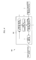
- a three-dimensional-image observation system 300 is configured so that an image-processing device 202 uses an affected region (target object) Y in images obtained by the image-acquisition device 1 as the attention point O of the observer.
- the image-processing device 2 is provided with an affected-region detecting portion (attention-point detecting portion) 11 that identifies the affected region Y in the parallax images received from the endoscope 1 and that calculates the center of gravity of the identified affected region Y as the attention point O.
- the affected-region detecting portion 11 stores images obtained by acquiring images of various types of affected region as reference images, searches the parallax images for regions that match the individual reference images or that are similar thereto, and calculates the centers of gravity of the matching regions as the attention points O.
- the affected-region detecting portion 11 follows the affected regions Y by continuing to match the previously-matched reference images and the affected regions Y, and obtains tracks of the attention points O by storing the positions of the centers of gravity of the affected regions Y over time.
- the auxiliary-indication creating portion 7 creates information about the individual affected regions Y as the auxiliary indications 9 and displays the auxiliary indications 9 for these affected regions Y in the vicinities of the affected regions Y so that the auxiliary indications 9 follow the movement of the affected regions Y in the three-dimensional image.
- the auxiliary-indication creating portion 7 receives from the affected-region detecting portion 11 a signal indicating that an affected region Y has been found, creates the auxiliary indication (local-information indication) 9 by prompting the observer to input a letter sequence which serves as the information about the affected region Y, and, in addition prompts the observer to specify a region at which to display the created auxiliary indication 9.
- Inputting the letter sequence and specifying the display region by the operator are, for example, performed by using a Graphical User Interface (GUI) provided in the auxiliary-indication creating portion 7.
- GUI Graphical User Interface
- the auxiliary-indication creating portion 7 receives the track of the attention point O from the affected-region detecting portion 11, and causes the auxiliary indication 9 to be moved along the same track as the attention point O. By doing so, the auxiliary indication 9 is moved in the three-dimensional image while maintaining a certain positional relationship with the affected region Y.
- the operator pays attention to the affected region Y. Therefore, also by detecting the affected region Y as the attention point O, it is possible to detect the attention point O of the observer with sufficiently high precision.
- the device configuration can be simplified as compared with the configuration in which the attention point O is calculated by detecting the lines of sight L1 and L2 of the observer.
- the auxiliary indication 9 as well as the corresponding affected region Y are moved along with the movement of the viewing field. Therefore, the observer can easily recognize the correspondence relationship between the auxiliary indication 9 and the affected region Y.
- the image-processing device 2 may issue a warning to that effect.
- a warning is displayed on the three-dimensional image in the case in which the auxiliary indication 9 falls outside the display area of the display portion 3 or in the case in which the auxiliary indication 9 is displayed at a position that overlaps with another affected region Y.
- the auxiliary-indication creating portion 7 prompts the observer to re-specify the position of the region at which to display the auxiliary indication 9 and displays it at the re-specified display position.
- a three-dimensional-image observation system is configured so that the auxiliary-indication creating portion 7 selects one of candidates 12a to 12h for the region at which to display the auxiliary indication 9 and displays the auxiliary indication 9 in the selected region among the candidates 12a to 12h.
- the auxiliary-indication creating portion 7 stores a plurality of candidates 12a to 12h for the region at which to display the auxiliary indication 9. Because the observer normally performs observation by placing the observation-target region at substantially the center of the three-dimensional image, it is preferable that regions serving as the candidates 12a to 12h be set at regions at peripheral portions of the parallax images so as not to overlap with the observation-target region used by the observer.
- the auxiliary-indication creating portion 7 stores the plurality of candidates 12a to 12h with priority ranks assigned thereto. Then, the auxiliary-indication creating portion 7 selects the candidate having the highest priority rank first, for example, the candidate 12a, calculates the parallax between the left and right parallax images at the position of the candidate 12a, and compares the calculated parallax with the parallax at the attention point O calculated by the parallax calculating portion 6. Then, if the parallax at the position of the candidate 12a is less than the parallax at the attention point O, the auxiliary-indication creating portion 7 displays the auxiliary indication 9 in the region of this candidate 12a.
- the auxiliary-indication creating portion 7 selects the second-ranking candidate, for example, the candidate 12b, and similarly compares the parallax at the position of the second-ranking candidate 12b with the parallax at the attention point O. Subsequently, the auxiliary-indication creating portion 7 repeats the same processing until a candidate for which the parallax at the position of the candidate is equal to or less than the parallax at the attention point 0 is found. By doing so, of the candidates 12a to 12h, a candidate at which the auxiliary indication 9 will be displayed at a position closer to the front than the tissue X is determined.
- the auxiliary indication 9 is displayed at a position closer to the front than the tissue X. By doing so, it is possible to prevent the occurrence of so-called embedding in which the auxiliary indication 9 is displayed at a position further back than the tissue X in the three-dimensional image (see broken lines in the figure).
- the auxiliary-indication creating portion 7 may be configured so as to prompt the observer to specify, of the plurality of candidates 12a to 12h, the candidate at which the auxiliary indication 9 will be displayed by using means such as a GUI or the like.
- the observer selects the candidate with which embedding does not occur based on the shape of the tissue X in the three-dimensional image.
- the auxiliary-indication creating portion 7 may store predetermined regions (for example, peripheral portions, lower portions, or the like of the parallax images) at which to display the auxiliary indication 9 instead of the plurality of candidates 12a to 12h, may select, from among the stored regions, a position at which the parallax would be smaller than the parallax at the attention point O, and may display the auxiliary indication 9 at the selected position.
- regions for example, peripheral portions, lower portions, or the like of the parallax images
- the display portion 3 may edit a portion of the three-dimensional image of the tissue X so that the tissue X would be displayed further back than the auxiliary indication 9 in the predetermined regions, and thus, embedding of the auxiliary indication 9 may be prevented in this way.
- the display portion 3 stores the predetermined regions at which to display the auxiliary indication 9, and assigns the same parallax as the parallax at the attention point O to regions in the parallax images that match the predetermined regions in the case in which the parallax at these regions is greater than the parallax at the attention point O. By doing so, a portion of the three-dimensional image is flattened, as shown in Fig. 7 .
- a three-dimensional-image observation system is configured so that, a plurality of degrees of urgency are set depending on the magnitude of values of the individual pieces of biometric information, and the auxiliary-indication creating portion 7 changes the indication form in accordance with the degree of urgency.
- the auxiliary-indication creating portion 7 creates the auxiliary indication 9 in a normal indication form.
- the auxiliary-indication creating portion 7 creates the auxiliary indication 9 in an indication form having a greater emphasis than the normal indication form.
- the emphasized indication form for example, color changes, enlarged display, blinking, rotation, vibration, or the like is employed.
- the degrees of urgency can be set in arbitrary steps.
- the auxiliary indication 9 for that biometric information will be displayed with emphasis in the three-dimensional image.
- the auxiliary-indication creating portion 7 may be configured so as to return the emphasized indication form to the normal indication form after confirming that the observer has paid attention to the emphasized information indication. Specifically, the auxiliary-indication creating portion 7 receives the calculated position of the attention point O from the attention-point calculating portion 5, and returns the auxiliary indication 9 to the normal indication form if the position of the attention point O matches the display region of the auxiliary indication 9. By doing so, it is possible to prevent a situation in which the observer is irritated by continuing to unnecessarily show the auxiliary indication 9 in an emphasized manner even after the observer has confirmed the abnormality in the subject.
- the auxiliary-indication creating portion 7 may be configured so that, in the case in which a measured value of the biometric information received from the biometric-information measuring device 8 corresponds to a higher degree of urgency, the auxiliary indication 9 is moved so as to follow the attention point O of the observer.
- the auxiliary-indication creating portion 7 displays the auxiliary indication 9 in a predetermined display region. Also, in the case in which the degree of urgency of the measured value received from the biometric-information measuring device 8 is increased, the auxiliary-indication creating portion 7 receives the calculated position of the attention point O from the attention-point calculating portion 5, and displays the auxiliary indication 9 in the vicinity of the position of the attention point O.
- the auxiliary indication 9 is moved, for example, from a peripheral portion of the three-dimensional image to the center portion of the three-dimensional image to which the observer is paying attention. Then, the auxiliary-indication creating portion 7 calculates the amount of movement of the attention point O, and causes the auxiliary indication 9 to follow the movement of the attention point O by adding the calculated amount of movement to the auxiliary indication 9 also.
- the auxiliary indication 9 following the movement of the attention point O may be stopped after continuing to do so for a predetermined amount of time or may be stopped when it is confirmed that the observer has paid attention to the auxiliary indication 9, as described above.
- the auxiliary indication 9 may be returned to the normal display region or may be deleted. In the case in which the auxiliary indication 9 is deleted, in order to make the observer recognize the auxiliary indication 9 even more strongly, the auxiliary indication 9 may be deleted gradually.
- a three-dimensional-image observation system is configured so that the auxiliary-indication creating portion 7 creates, as the auxiliary indications 9, a local-information indication about a specific position in the tissue X and an arrow that indicates the specific position indicated by the local-information indication.
- the auxiliary-indication creating portion 7 creates, as the auxiliary indications 9, a letter sequence (local-information indication) about that affected region Y and an arrow that points at the affected region Y.
- a letter sequence local-information indication
- the auxiliary-indication creating portion 7 creates a letter sequence 9a that reads "tumor” and an arrow 9b that points at the position of the tumor Y indicated by the letter sequence 9a.
- the letter sequence 9a is input by the observer by, for example, using a keyboard.
- Positions of a starting point (base of the arrow 9b) and an ending point (tip of the arrow 9b) of the arrow 9b in the direction of a plane are specified by the observer by, for example, using a GUI provided in the auxiliary-indication creating portion 7.
- the auxiliary-indication creating portion 7 assigns the same parallax as the letter sequence 9a to the starting point of the arrow 9b and the same parallax as the tumor Y serving as the specific position to the ending point of the arrow 9b. Then, as shown in Fig. 9B , the auxiliary-indication creating portion 7 creates the arrow 9b in which the parallax gradually changes from the starting point toward the ending point.
- the letter sequence 9a is displayed at the same depthwise position as the tumor Y in the three-dimensional image when the observer is paying attention to the tumor Y, it is easy to recognize that the letter sequence 9a corresponds to the tumor Y.
- the observer is paying attention to a position other than the tumor Y, it is difficult to recognize that the letter sequence 9a corresponds to the tumor Y partly because the letter sequence 9a and the tumor Y are displayed at different depthwise positions.
- the auxiliary-indication creating portion 7 may be configured so as to set the starting point and the ending point of the arrow 9b.
- the image-processing device 2 is provided with an affected-region identifying portion (not shown) that receives a special-light image from the endoscope 1 and that identifies an affected region in the special-light image.
- the endoscope 1 has a normal mode for obtaining a white-light image of the tissue X inside the body and a special mode for obtaining a special-light image of the tissue X inside the body, and the normal mode and the special mode are switched when the observer switches a switch (not shown).
- the special-light image is, for example, a fluorescence image, a narrowband-light image, or an IR-light image. In the special-light image, the affected region is observed to have a different luminance value or hue than the peripheral portions.
- the affected-region identifying portion identifies a region having a higher luminance value than the peripheral portions or a region having different hue than the peripheral portions. Then, the auxiliary-indication creating portion 7 sets the starting point of the arrow 9b at an end of the region in which the letter sequence 9a is to be displayed and sets the ending point of the arrow 9b at the center of the affected region identified by the affected-region identifying portion.
- the observer checks the presence/absence of the affected region by using the special mode.
- the arrow 9b indicating the affected region is created by the auxiliary-indication creating portion 7, and the arrow 9b is displayed in the three-dimensional image.
- This arrow 9b continues to be displayed in the three-dimensional image based on the white-light image even after the observer switches the operation to the normal mode. By doing so, operations performed by the observer to specify the starting point and the ending point of the arrow 9b are eliminated, thus making it possible to reduce the burden on the observer.
- the auxiliary-indication creating portion 7 may switch between display and non-display of the auxiliary indication 9 in accordance with the attention point O of the observer.
- the auxiliary-indication creating portion 7 receives the calculated position of the attention point O from the attention-point calculating portion 5, and, in the case in which the position of the attention point O matches the position of the affected region Y, displays the letter sequence 9a about the affected region Y and the arrow 9b in the auxiliary-indication parallax images.
- the letter sequence 9a about the affected region Y and the arrow 9b are deleted from the auxiliary-indication parallax images.
- the auxiliary indication 9 related to the specific positions the auxiliary indication 9 related to the specific position to which the observer is currently paying attention is displayed on the three-dimensional image, and the auxiliary indications 9 that the observer does not currently need are deleted from the three-dimensional image. Accordingly, it is possible to prevent the three-dimensional image from becoming unnecessarily complicated.
Landscapes
- Engineering & Computer Science (AREA)
- Health & Medical Sciences (AREA)
- Life Sciences & Earth Sciences (AREA)
- Signal Processing (AREA)
- Multimedia (AREA)
- Surgery (AREA)
- Animal Behavior & Ethology (AREA)
- Veterinary Medicine (AREA)
- Pathology (AREA)
- Optics & Photonics (AREA)
- Biomedical Technology (AREA)
- Heart & Thoracic Surgery (AREA)
- Medical Informatics (AREA)
- Molecular Biology (AREA)
- Physics & Mathematics (AREA)
- General Health & Medical Sciences (AREA)
- Public Health (AREA)
- Radiology & Medical Imaging (AREA)
- Nuclear Medicine, Radiotherapy & Molecular Imaging (AREA)
- Biophysics (AREA)
- Human Computer Interaction (AREA)
- Endoscopes (AREA)
- Instruments For Viewing The Inside Of Hollow Bodies (AREA)
- Processing Or Creating Images (AREA)
- Image Processing (AREA)
- Testing, Inspecting, Measuring Of Stereoscopic Televisions And Televisions (AREA)
- Controls And Circuits For Display Device (AREA)
- Image Analysis (AREA)
- Eye Examination Apparatus (AREA)
- Closed-Circuit Television Systems (AREA)
Applications Claiming Priority (2)
| Application Number | Priority Date | Filing Date | Title |
|---|---|---|---|
| JP2012134686A JP6103827B2 (ja) | 2012-06-14 | 2012-06-14 | 画像処理装置および立体画像観察システム |
| PCT/JP2013/061142 WO2013187116A1 (ja) | 2012-06-14 | 2013-04-15 | 画像処理装置および立体画像観察システム |
Publications (2)
| Publication Number | Publication Date |
|---|---|
| EP2863634A1 true EP2863634A1 (de) | 2015-04-22 |
| EP2863634A4 EP2863634A4 (de) | 2016-02-24 |
Family
ID=49757954
Family Applications (1)
| Application Number | Title | Priority Date | Filing Date |
|---|---|---|---|
| EP13803595.1A Ceased EP2863634A4 (de) | 2012-06-14 | 2013-04-15 | Bildverarbeitungsvorrichtung und system zur anzeige dreidimensionaler bilder |
Country Status (5)
| Country | Link |
|---|---|
| US (1) | US20150077529A1 (de) |
| EP (1) | EP2863634A4 (de) |
| JP (1) | JP6103827B2 (de) |
| CN (1) | CN104335580A (de) |
| WO (1) | WO2013187116A1 (de) |
Cited By (2)
| Publication number | Priority date | Publication date | Assignee | Title |
|---|---|---|---|---|
| CN108521568A (zh) * | 2018-03-26 | 2018-09-11 | 天津大学 | 基于显著性区域的立体图像舒适度视差范围的测定方法 |
| EP3360461A4 (de) * | 2015-11-10 | 2019-05-08 | Olympus Corporation | Endoskopvorrichtung |
Families Citing this family (22)
| Publication number | Priority date | Publication date | Assignee | Title |
|---|---|---|---|---|
| WO2015029318A1 (ja) * | 2013-08-26 | 2015-03-05 | パナソニックIpマネジメント株式会社 | 3次元表示装置および3次元表示方法 |
| JP5893808B2 (ja) * | 2014-01-24 | 2016-03-23 | オリンパス株式会社 | 立体内視鏡画像処理装置 |
| EP3795068B1 (de) | 2014-02-27 | 2024-07-24 | Intuitive Surgical Operations, Inc. | System und verfahren zur detektion und reduzierung von spiegelreflexion |
| JPWO2015145933A1 (ja) * | 2014-03-26 | 2017-04-13 | パナソニックIpマネジメント株式会社 | 虚像表示装置、ヘッドアップディスプレイシステム及び乗物 |
| JP6323183B2 (ja) * | 2014-06-04 | 2018-05-16 | ソニー株式会社 | 画像処理装置および画像処理方法 |
| JP6323184B2 (ja) * | 2014-06-04 | 2018-05-16 | ソニー株式会社 | 画像処理装置、画像処理方法、並びにプログラム |
| CN105812778B (zh) * | 2015-01-21 | 2018-02-02 | 成都理想境界科技有限公司 | 双目ar头戴显示设备及其信息显示方法 |
| CN105992546B (zh) * | 2015-01-21 | 2018-08-28 | Hoya株式会社 | 内窥镜系统 |
| JP6707083B2 (ja) * | 2015-06-29 | 2020-06-10 | オリンパス株式会社 | 画像処理装置、内視鏡システム、画像処理方法、及び画像処理プログラム |
| JP6828695B2 (ja) * | 2016-02-12 | 2021-02-10 | ソニー株式会社 | 医療用画像処理装置、システム、方法及びプログラム |
| CN108778093B (zh) * | 2016-04-19 | 2021-01-05 | 奥林巴斯株式会社 | 内窥镜系统 |
| CN107515474B (zh) * | 2017-09-22 | 2020-03-31 | 宁波维真显示科技股份有限公司 | 自动立体显示方法、装置及立体显示设备 |
| WO2019087790A1 (ja) | 2017-10-31 | 2019-05-09 | 富士フイルム株式会社 | 検査支援装置、内視鏡装置、検査支援方法、及び検査支援プログラム |
| CN108065904A (zh) * | 2018-01-02 | 2018-05-25 | 京东方科技集团股份有限公司 | 内窥镜系统及其控制方法 |
| JPWO2019181212A1 (ja) * | 2018-03-23 | 2021-03-11 | ソニー・オリンパスメディカルソリューションズ株式会社 | 医療用表示制御装置、および表示制御方法 |
| EP3779047A4 (de) | 2018-03-30 | 2021-04-21 | Sumitomo (S.H.I.) Construction Machinery Co., Ltd. | Strassenmaschine |
| US11357593B2 (en) | 2019-01-10 | 2022-06-14 | Covidien Lp | Endoscopic imaging with augmented parallax |
| WO2020166528A1 (ja) * | 2019-02-13 | 2020-08-20 | 日本電気株式会社 | 施術支援装置、施術支援方法、及びコンピュータ読み取り可能な記録媒体 |
| US11937767B2 (en) | 2019-07-18 | 2024-03-26 | Hoya Corporation | Endoscope |
| JP7375022B2 (ja) * | 2019-08-29 | 2023-11-07 | オリンパス株式会社 | 画像処理装置の作動方法、制御装置、および内視鏡システム |
| WO2021158305A1 (en) * | 2020-02-04 | 2021-08-12 | Covidien Lp | Systems and methods for machine readable identification of surgical tools in-situ |
| CN116158718A (zh) * | 2023-03-13 | 2023-05-26 | 武汉迈瑞医疗技术研究院有限公司 | 用于内窥镜系统的成像及显示方法和内窥镜系统 |
Family Cites Families (17)
| Publication number | Priority date | Publication date | Assignee | Title |
|---|---|---|---|---|
| JP3432035B2 (ja) * | 1995-03-24 | 2003-07-28 | 日本コーリン株式会社 | 内視鏡用生体情報表示装置 |
| US6064354A (en) * | 1998-07-01 | 2000-05-16 | Deluca; Michael Joseph | Stereoscopic user interface method and apparatus |
| JP2003325444A (ja) * | 2002-05-10 | 2003-11-18 | Pentax Corp | 電子内視鏡装置および映像信号処理装置 |
| US20070167702A1 (en) * | 2005-12-30 | 2007-07-19 | Intuitive Surgical Inc. | Medical robotic system providing three-dimensional telestration |
| US8320992B2 (en) * | 2006-10-05 | 2012-11-27 | Visionsense Ltd. | Method and system for superimposing three dimensional medical information on a three dimensional image |
| JP2009239722A (ja) * | 2008-03-27 | 2009-10-15 | Toshiba Corp | 映像モニタシステム、ビデオサーバ、および映像モニタ方法 |
| US8808164B2 (en) * | 2008-03-28 | 2014-08-19 | Intuitive Surgical Operations, Inc. | Controlling a robotic surgical tool with a display monitor |
| JP5238440B2 (ja) * | 2008-10-02 | 2013-07-17 | 株式会社東芝 | 画像表示装置及び画像表示方法 |
| US8641621B2 (en) * | 2009-02-17 | 2014-02-04 | Inneroptic Technology, Inc. | Systems, methods, apparatuses, and computer-readable media for image management in image-guided medical procedures |
| CN102318352B (zh) * | 2009-02-17 | 2014-12-10 | 皇家飞利浦电子股份有限公司 | 组合3d图像和图形数据 |
| US9155592B2 (en) * | 2009-06-16 | 2015-10-13 | Intuitive Surgical Operations, Inc. | Virtual measurement tool for minimally invasive surgery |
| JP5620651B2 (ja) * | 2009-06-26 | 2014-11-05 | キヤノン株式会社 | 再生装置、撮像装置、及びその制御方法 |
| JP5395538B2 (ja) * | 2009-06-30 | 2014-01-22 | 株式会社東芝 | 超音波診断装置及び画像データ表示用制御プログラム |
| JP5369952B2 (ja) * | 2009-07-10 | 2013-12-18 | ソニー株式会社 | 情報処理装置および情報処理方法 |
| JP2011180779A (ja) | 2010-02-26 | 2011-09-15 | Brother Industries Ltd | 立体画像データ生成装置、立体画像データ生成方法、および立体画像データ生成プログラム |
| JP2012065698A (ja) * | 2010-09-21 | 2012-04-05 | Fujifilm Corp | 手術支援システムおよびそれを用いた手術支援方法 |
| JP2012075508A (ja) * | 2010-09-30 | 2012-04-19 | Panasonic Corp | 手術用カメラ |
-
2012
- 2012-06-14 JP JP2012134686A patent/JP6103827B2/ja not_active Expired - Fee Related
-
2013
- 2013-04-15 CN CN201380027833.0A patent/CN104335580A/zh active Pending
- 2013-04-15 EP EP13803595.1A patent/EP2863634A4/de not_active Ceased
- 2013-04-15 WO PCT/JP2013/061142 patent/WO2013187116A1/ja not_active Ceased
-
2014
- 2014-11-25 US US14/553,205 patent/US20150077529A1/en not_active Abandoned
Cited By (3)
| Publication number | Priority date | Publication date | Assignee | Title |
|---|---|---|---|---|
| EP3360461A4 (de) * | 2015-11-10 | 2019-05-08 | Olympus Corporation | Endoskopvorrichtung |
| US10863893B2 (en) | 2015-11-10 | 2020-12-15 | Olympus Corporation | Endoscope apparatus |
| CN108521568A (zh) * | 2018-03-26 | 2018-09-11 | 天津大学 | 基于显著性区域的立体图像舒适度视差范围的测定方法 |
Also Published As
| Publication number | Publication date |
|---|---|
| JP2013258627A (ja) | 2013-12-26 |
| CN104335580A (zh) | 2015-02-04 |
| EP2863634A4 (de) | 2016-02-24 |
| JP6103827B2 (ja) | 2017-03-29 |
| US20150077529A1 (en) | 2015-03-19 |
| WO2013187116A1 (ja) | 2013-12-19 |
Similar Documents
| Publication | Publication Date | Title |
|---|---|---|
| EP2863634A1 (de) | Bildverarbeitungsvorrichtung und system zur anzeige dreidimensionaler bilder | |
| US12175607B2 (en) | Enhanced augmented reality headset for medical imaging | |
| US11301034B2 (en) | Display device, control method for display device, and computer program | |
| AU2016362664B2 (en) | Location indicator for optical coherence tomography in ophthalmic visualization | |
| EP2543308B1 (de) | Fluoreszenzbeobachtungsgerät | |
| US11094283B2 (en) | Head-wearable presentation apparatus, method for operating the same, and medical-optical observation system | |
| JP5580758B2 (ja) | 蛍光観察装置 | |
| EP3279780A1 (de) | Informationsverarbeitungsvorrichtung, informationsverarbeitungsverfahren und informationsverarbeitungssystem | |
| JP6661656B2 (ja) | 医療機器 | |
| KR102097390B1 (ko) | 시선 검출 기반의 스마트 안경 표시 장치 | |
| US20250185885A1 (en) | Visualization system comprising an observation apparatus and an endoscope | |
| US10743743B2 (en) | Medical observation apparatus | |
| EP4333763B1 (de) | Headset mit erweiterter realität und sonde für medizinische bildgebung | |
| WO2022234156A1 (en) | Enhanced augmented reality headset for medical imaging | |
| JP2017055233A (ja) | 表示装置、表示システム、及び、表示装置の制御方法 | |
| JP7017385B2 (ja) | 頭部装着型表示装置、表示システム及び表示方法 | |
| US20260120366A1 (en) | Method for generating an augmented image representation by a medical visualization system, and medical visualization system | |
| US20250118011A1 (en) | System for visualizing oct signals |
Legal Events
| Date | Code | Title | Description |
|---|---|---|---|
| PUAI | Public reference made under article 153(3) epc to a published international application that has entered the european phase |
Free format text: ORIGINAL CODE: 0009012 |
|
| 17P | Request for examination filed |
Effective date: 20150107 |
|
| AK | Designated contracting states |
Kind code of ref document: A1 Designated state(s): AL AT BE BG CH CY CZ DE DK EE ES FI FR GB GR HR HU IE IS IT LI LT LU LV MC MK MT NL NO PL PT RO RS SE SI SK SM TR |
|
| AX | Request for extension of the european patent |
Extension state: BA ME |
|
| DAX | Request for extension of the european patent (deleted) | ||
| RA4 | Supplementary search report drawn up and despatched (corrected) |
Effective date: 20160122 |
|
| RIC1 | Information provided on ipc code assigned before grant |
Ipc: H04N 13/00 20060101ALI20160118BHEP Ipc: A61B 1/00 20060101ALI20160118BHEP Ipc: G02B 23/24 20060101ALI20160118BHEP Ipc: H04N 7/18 20060101ALI20160118BHEP Ipc: H04N 13/04 20060101AFI20160118BHEP Ipc: G06T 1/00 20060101ALI20160118BHEP |
|
| RAP1 | Party data changed (applicant data changed or rights of an application transferred) |
Owner name: OLYMPUS CORPORATION |
|
| RIN1 | Information on inventor provided before grant (corrected) |
Inventor name: NARUSE, MASATO Inventor name: HARAGUCHI, MASAFUMI Inventor name: HATTA, IZUMI Inventor name: SAKAMOTO, JOJI |
|
| STAA | Information on the status of an ep patent application or granted ep patent |
Free format text: STATUS: EXAMINATION IS IN PROGRESS |
|
| 17Q | First examination report despatched |
Effective date: 20170418 |
|
| STAA | Information on the status of an ep patent application or granted ep patent |
Free format text: STATUS: THE APPLICATION HAS BEEN REFUSED |
|
| REG | Reference to a national code |
Ref country code: DE Ref legal event code: R003 |
|
| 18R | Application refused |
Effective date: 20171113 |