EP2863688B1 - Konzept für Sendeleistungseinstellung in einem zellularen Kommunikationsystem - Google Patents
Konzept für Sendeleistungseinstellung in einem zellularen Kommunikationsystem Download PDFInfo
- Publication number
- EP2863688B1 EP2863688B1 EP13306426.1A EP13306426A EP2863688B1 EP 2863688 B1 EP2863688 B1 EP 2863688B1 EP 13306426 A EP13306426 A EP 13306426A EP 2863688 B1 EP2863688 B1 EP 2863688B1
- Authority
- EP
- European Patent Office
- Prior art keywords
- cell
- power control
- performance
- iot
- fom
- Prior art date
- Legal status (The legal status is an assumption and is not a legal conclusion. Google has not performed a legal analysis and makes no representation as to the accuracy of the status listed.)
- Not-in-force
Links
- 230000010267 cellular communication Effects 0.000 title claims description 18
- 238000000034 method Methods 0.000 claims description 53
- 230000003595 spectral effect Effects 0.000 claims description 17
- 230000003247 decreasing effect Effects 0.000 claims description 6
- 238000004590 computer program Methods 0.000 claims description 4
- 230000006870 function Effects 0.000 description 15
- 230000002123 temporal effect Effects 0.000 description 14
- 238000009826 distribution Methods 0.000 description 9
- 239000011159 matrix material Substances 0.000 description 7
- 230000008859 change Effects 0.000 description 5
- 238000013459 approach Methods 0.000 description 4
- 230000001419 dependent effect Effects 0.000 description 4
- 238000010586 diagram Methods 0.000 description 4
- 230000007246 mechanism Effects 0.000 description 4
- 230000006978 adaptation Effects 0.000 description 3
- 238000005259 measurement Methods 0.000 description 3
- 230000001413 cellular effect Effects 0.000 description 2
- 238000004891 communication Methods 0.000 description 2
- 238000012937 correction Methods 0.000 description 2
- 230000001186 cumulative effect Effects 0.000 description 2
- 238000005315 distribution function Methods 0.000 description 2
- 238000012986 modification Methods 0.000 description 2
- 230000004048 modification Effects 0.000 description 2
- 238000012544 monitoring process Methods 0.000 description 2
- 238000005457 optimization Methods 0.000 description 2
- 230000010355 oscillation Effects 0.000 description 2
- 238000004088 simulation Methods 0.000 description 2
- 230000032683 aging Effects 0.000 description 1
- 230000006399 behavior Effects 0.000 description 1
- 230000005540 biological transmission Effects 0.000 description 1
- 230000015556 catabolic process Effects 0.000 description 1
- 238000006243 chemical reaction Methods 0.000 description 1
- 230000000295 complement effect Effects 0.000 description 1
- 238000006731 degradation reaction Methods 0.000 description 1
- 238000005562 fading Methods 0.000 description 1
- 230000007774 longterm Effects 0.000 description 1
- 239000000203 mixture Substances 0.000 description 1
- 230000000737 periodic effect Effects 0.000 description 1
- 230000008569 process Effects 0.000 description 1
- 230000000135 prohibitive effect Effects 0.000 description 1
- 230000004044 response Effects 0.000 description 1
- 238000010972 statistical evaluation Methods 0.000 description 1
- 238000007619 statistical method Methods 0.000 description 1
- 230000007704 transition Effects 0.000 description 1
Images




Classifications
-
- H—ELECTRICITY
- H04—ELECTRIC COMMUNICATION TECHNIQUE
- H04W—WIRELESS COMMUNICATION NETWORKS
- H04W52/00—Power management, e.g. Transmission Power Control [TPC] or power classes
- H04W52/04—Transmission power control [TPC]
- H04W52/18—TPC being performed according to specific parameters
- H04W52/24—TPC being performed according to specific parameters using SIR [Signal to Interference Ratio] or other wireless path parameters
- H04W52/243—TPC being performed according to specific parameters using SIR [Signal to Interference Ratio] or other wireless path parameters taking into account interferences
-
- H—ELECTRICITY
- H04—ELECTRIC COMMUNICATION TECHNIQUE
- H04W—WIRELESS COMMUNICATION NETWORKS
- H04W52/00—Power management, e.g. Transmission Power Control [TPC] or power classes
- H04W52/04—Transmission power control [TPC]
- H04W52/06—TPC algorithms
- H04W52/14—Separate analysis of uplink or downlink
- H04W52/146—Uplink power control
-
- H—ELECTRICITY
- H04—ELECTRIC COMMUNICATION TECHNIQUE
- H04W—WIRELESS COMMUNICATION NETWORKS
- H04W52/00—Power management, e.g. Transmission Power Control [TPC] or power classes
- H04W52/04—Transmission power control [TPC]
- H04W52/18—TPC being performed according to specific parameters
- H04W52/26—TPC being performed according to specific parameters using transmission rate or quality of service QoS [Quality of Service]
- H04W52/267—TPC being performed according to specific parameters using transmission rate or quality of service QoS [Quality of Service] taking into account the information rate
-
- H—ELECTRICITY
- H04—ELECTRIC COMMUNICATION TECHNIQUE
- H04W—WIRELESS COMMUNICATION NETWORKS
- H04W28/00—Network traffic management; Network resource management
- H04W28/16—Central resource management; Negotiation of resources or communication parameters, e.g. negotiating bandwidth or QoS [Quality of Service]
- H04W28/18—Negotiating wireless communication parameters
-
- H—ELECTRICITY
- H04—ELECTRIC COMMUNICATION TECHNIQUE
- H04W—WIRELESS COMMUNICATION NETWORKS
- H04W52/00—Power management, e.g. Transmission Power Control [TPC] or power classes
- H04W52/04—Transmission power control [TPC]
- H04W52/06—TPC algorithms
- H04W52/10—Open loop power control
-
- H—ELECTRICITY
- H04—ELECTRIC COMMUNICATION TECHNIQUE
- H04W—WIRELESS COMMUNICATION NETWORKS
- H04W52/00—Power management, e.g. Transmission Power Control [TPC] or power classes
- H04W52/04—Transmission power control [TPC]
- H04W52/18—TPC being performed according to specific parameters
- H04W52/22—TPC being performed according to specific parameters taking into account previous information or commands
- H04W52/226—TPC being performed according to specific parameters taking into account previous information or commands using past references to control power, e.g. look-up-table
-
- H—ELECTRICITY
- H04—ELECTRIC COMMUNICATION TECHNIQUE
- H04W—WIRELESS COMMUNICATION NETWORKS
- H04W52/00—Power management, e.g. Transmission Power Control [TPC] or power classes
- H04W52/04—Transmission power control [TPC]
- H04W52/18—TPC being performed according to specific parameters
- H04W52/22—TPC being performed according to specific parameters taking into account previous information or commands
- H04W52/228—TPC being performed according to specific parameters taking into account previous information or commands using past power values or information
-
- H—ELECTRICITY
- H04—ELECTRIC COMMUNICATION TECHNIQUE
- H04W—WIRELESS COMMUNICATION NETWORKS
- H04W52/00—Power management, e.g. Transmission Power Control [TPC] or power classes
- H04W52/04—Transmission power control [TPC]
- H04W52/18—TPC being performed according to specific parameters
- H04W52/24—TPC being performed according to specific parameters using SIR [Signal to Interference Ratio] or other wireless path parameters
- H04W52/242—TPC being performed according to specific parameters using SIR [Signal to Interference Ratio] or other wireless path parameters taking into account path loss
-
- H—ELECTRICITY
- H04—ELECTRIC COMMUNICATION TECHNIQUE
- H04W—WIRELESS COMMUNICATION NETWORKS
- H04W52/00—Power management, e.g. Transmission Power Control [TPC] or power classes
- H04W52/04—Transmission power control [TPC]
- H04W52/30—Transmission power control [TPC] using constraints in the total amount of available transmission power
- H04W52/36—Transmission power control [TPC] using constraints in the total amount of available transmission power with a discrete range or set of values, e.g. step size, ramping or offsets
- H04W52/362—Aspects of the step size
-
- H—ELECTRICITY
- H04—ELECTRIC COMMUNICATION TECHNIQUE
- H04W—WIRELESS COMMUNICATION NETWORKS
- H04W52/00—Power management, e.g. Transmission Power Control [TPC] or power classes
- H04W52/04—Transmission power control [TPC]
- H04W52/38—TPC being performed in particular situations
- H04W52/40—TPC being performed in particular situations during macro-diversity or soft handoff
-
- H—ELECTRICITY
- H04—ELECTRIC COMMUNICATION TECHNIQUE
- H04W—WIRELESS COMMUNICATION NETWORKS
- H04W92/00—Interfaces specially adapted for wireless communication networks
- H04W92/16—Interfaces between hierarchically similar devices
- H04W92/20—Interfaces between hierarchically similar devices between access points
Definitions
- Embodiments generally relate to communication systems and, in particular, to power control methods and apparatuses for cellular communication systems.
- Power control may be subdivided into downlink (direction from a base station to associated mobile terminals) power control and uplink (direction from mobile terminals to their serving base station) power control.
- Uplink power control for example, is a key radio resource management function. Uplink system performance depends on proper operation of its respective power control. It determines on one hand the signal level at the receiver (base station) and on the other hand how much interference a mobile terminal causes in neighbor cell.
- embodiments provide a power control method for a cellular communication system.
- the method includes determining a first performance of a first cell.
- An uplink power control parameter for the first cell is varied to maximize the first performance.
- the method includes determining a second performance of one or more cells adjacent to the first cell.
- a target interference level is varied to maximize the second performance.
- inventions provide a power control apparatus for a cellular communication system.
- the apparatus includes a processor to determine a first performance of a first cell.
- the apparatus includes a processor to vary an uplink power control parameter for the first cell to maximize the first performance.
- the apparatus includes a processor to determine a second performance of one or more cells adjacent to the first cell.
- the apparatus includes a processor to vary a target interference level to maximize the second performance.
- Some embodiments comprise a digital control circuit installed within the power control apparatus.
- a digital control circuit e.g. a Digital Signal Processor (DSP), a Field-Programmable Gate Array (FPGA), an Application-Specific Integrated Circuit (ASIC), or a general purpose processor, needs to be programmed accordingly.
- DSP Digital Signal Processor
- FPGA Field-Programmable Gate Array
- ASIC Application-Specific Integrated Circuit
- yet further embodiments also provide a computer program having a program code for performing embodiments of the power control method, when the computer program is executed on a programmable hardware device.
- Uplink system performance strongly depends on proper operation of its respective power control, which plays an important role for the uplink of cellular networks, such as Long Term Evolution (LTE), for example.
- Uplink power control may determine on the one hand a signal level at a base station receiver and on the other hand how much interference one or more mobiles cause in neighbor cells.
- the LTE standard has defined a combination of so-called open loop and closed loop power control.
- the open loop part of the scheme may also be called Fractional Power Control (FPC) because it allows User Equipments (UE) to partially compensate for path-loss between a base station and the UE.
- FPC may be characterized by two main parameters: a value P 0 indicative of a target received power and a compensation factor ⁇ .
- Power control has been a major radio feature of 3 rd Generation (3G) Wideband Code Division Multiple Access (WCDMA) cellular networks.
- 3G 3 rd Generation
- WCDMA Wideband Code Division Multiple Access
- fast power control follows variations of a wireless channel (path-loss, shadowing and fast fading) in order to limit as much as possible intra-cell interference, i.e., interference between users associated with the same cell.
- HSPA High-Speed Packet Access
- HSPA High-Speed Packet Access
- HSPA High-Speed Packet Access
- HSPA High-Speed Packet Access
- HSPA High-Speed Packet Access
- HSPA High-Speed Packet Access
- HSPA High-Speed Packet Access
- HSPA High-Speed Packet Access
- HSPA High-Speed Packet Access
- HSPA High-Speed Packet Access
- HSPA High-Speed Packet Access
- HSPA High-Speed Packet Access
- HSPA High-Speed Packet Access
- HSPA High
- LTE abandons fast power control both on the downlink and on the uplink, as the resources allocated to different users of a given cell are orthogonal.
- OFDMA Orthogonal Frequency-Division Multiple Access
- SC-FDMA Single-Carrier Frequency-Division Multiple Access
- a fast link adaptation scheme As in HSDPA, fast variations of the radio channels are considered by a fast link adaptation scheme and a scheduler.
- power control is responsible for setting a UE's transmitted power per SC-FDMA symbol.
- One of its goals is to reduce the power emitted by UEs that are important sources of interference for neighbor cells, i.e., UEs at the cell edge.
- it comprises two parts: an open loop scheme based on UE own measurements; and a closed loop scheme based on commands sent by the base station or eNodeB, as it may be called according to 3GPP terminology.
- PRB Physical Resource Blocks
- the latter mechanism represents the closed-loop component of uplink power control.
- changes in the power setting due to closed-loop corrections occur more frequent than changes in open-loop power control parameter settings. Therefore, it is often said that the closed-loop power control is fast relative to the open-loop control component.
- the terminus "fast" is relative and depends on the vendor specific implementation of the power control mechanism.
- the UE's power control parameter setting with respect to P 0 and/or ⁇ may be determined by its serving cell. Thereby the serving cell may be determined by the UE via so-called downlink Reference Signal Received Power (RSRP) measurements.
- the RSRP measurement of the signal strength of an LTE cell may help to rank between the different cells as input for handover and cell reselection decisions, for example.
- the RSRP is the average of the power of all physical resource elements which carry cell-specific reference signals over the entire bandwidth. It may therefore be measured in the OFDM symbols carrying reference symbols.
- each cell of a wireless network may periodically send an overload indicator (for example. 1 bit) to its neighbor cells.
- the overload indicator may be set to true if an average Interference-over-Thermal (IoT) figure is larger than a target value, otherwise it may be set to false.
- Each cell may receive overload indicators from its neighbor cells. Further, each cell may periodically determine whether or not it may be responsible for an overload situation in a neighbor cell. Depending on the result the cell may decrease or increase its target receive-power spectral density for its served mobiles, i.e., the P 0 parameter may be adjusted by ⁇ 1dB per adaptation event, for example.
- a UE may employ a layer 3 filter to average the path loss in time.
- the layer 3 filter uses the last three measured downlink path loss values for calculating an average value.
- the last three measured downlink path loss values may be weighted differently. For example, a most recent value may get a higher weight than a previously measured value.
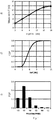
- Fig. 1a illustrates a measured Interference-over-Thermal (IoT) figure as function of a target IoT for the reference power control implementation.
- the Interference-over-Thermal (IoT) or Rise-over-Thermal (ROT) indicates the ratio between the total interference received at a base station and the thermal noise. IoT may hence be regarded as an interference level.
- the target IoT may be a fixed constant for all cells. It may be observed from Fig. 1a that the desired (average) IoT may almost always be achieved by the reference power control implementation. Only high IoT values cannot be achieved because of the UE's power limitation.
- Fig. 1b shows an IoT Cumulative Distribution Function (CDF) curve for an example of 6 dB target IoT targeted with the reference power control implementation.
- CDF Cumulative Distribution Function
- the depicted CDF describes the probability that a real-valued random variable X IoT in this case) with a given probability distribution will be found at a value less than or equal to x. From the IoT CDF curve of Fig. 1b it can be seen that a large fraction of measured cell IoT values is indeed close to the targeted value.
- Fig. 1c shows the corresponding receive-power spectral density distribution, i.e. P 0 [dBm/PRB]. The P 0 values are located around -87 dBm/PRB in this example.
- Fig. 2a shows a cell-edge user SPectral Efficiency (SPE) for the reference power control implementation with a maximum at about 6dB IoT in this example.
- Fig. 2b shows the cell spectral efficiency as function of the measured IoT. The maximum in this example is at about 12dB IoT.
- the cell-edge user spectral efficiency and/or the cell spectral efficiency may be regarded as different measures of performances for a radio cell.
- a joint Figure Of Merit (FOM) may be defined as the product of the cell-edge user SPE (see Fig. 2a ) and the cell SPE (see Fig. 2b ).
- Such a definition of a quality or performance indicator may allow finding a good compromise between the cell-edge and overall cell performance. In the example case the optimum IoT would be about 6 dB, see Fig. 2c .
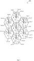
- Fig. 3 schematically illustrates a cellular communication system 300, such as an LTE system, for example.
- the cellular communication system 300 comprises a plurality of radio cells 310-1 to 310-7.
- a radio cell 310 may be further subdivided into a plurality of cell sectors, for example.
- a radio cell (short: cell) and a sector may be distinguished from other cells and sectors by means of a unique cell identifier (cell ID), respectively.
- a cell has a unique cell ID.
- a sector has a unique cell-ID.
- a sector may therefore as well be understood as a unique cell.
- the cells 310-1 to 310-7 are served by base stations 312-1 to 312-7, respectively.
- the base stations 312-1 to 312-7 have associated therewith a plurality of UEs 314-1 to 314-7, respectively.
- the base stations 312-1 to 312-7 transmit downlink signals to their associated UEs 314-1 to 314-7.
- the UEs 314-1 to 314-7 transmit uplink signals to their serving base stations 312-1 to 312-7. If the uplink transmission is not coordinated appropriately by power control concepts prohibitive inter-cell interference is possible.
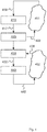
- some embodiments relate to an iterative power control method 400 for a cellular communication system 300.
- the method 400 or an iteration thereof comprises an act 410 of determining a first performance 412 of a first cell or an indicator thereof. This may be done based on one or more measured performance quantities 408. For example, let us consider cell 310-1 as the first cell.
- an uplink power control parameter 422 is varied for the first cell 310-1 to maximize the first performance 412.
- a second performance 432 of one or more cells 310-2 to 310-7 adjacent to the first cell 310-1 or an indicator thereof is determined. This may be done based on one or more measured performance quantities 428.
- a target interference level 442 is varied to maximize the second performance 432.
- Method 400 may be carried out by a power control apparatus for a cellular communication system.
- the apparatus comprises a processor to determine the first performance 412 (or an indicator thereof) of the first cell 310-1.
- Said processor or another processor is further operable to vary the uplink power control parameter 422 for the first cell 310-1 to maximize the first performance 412.
- the processor or another processor is further operable to determine the second performance 432 (or an indicator thereof) of cells 310-2 to 310-7 adjacent to the first cell 310-1.
- Said processor or another processor is further operable to vary the target interference level 442 to maximize the second performance 432.
- reference numerals 451, 452 represent reactions of the cellular communication system 300 or parts thereof in response to the variations of the uplink power control parameter 422 and/or the target interference level 442.
- the uplink power (the UEs transmit power) in the first cell 310-1 may vary as well.
- varying the target interference level 442 for the cellular communication system 300 or parts thereof may lead to different experienced uplink powers and interference levels in the cells 310-1 to 310-7.
- updated performance quantities 408 of the first cell 310-1 and/or updated performance quantities 428 of the cells 310-2 to 310-7 adjacent to the first cell 310-1 may be measured in a subsequent iteration of method 400.
- the performance quantities 408 of the first cell 310-1 may be subdivided into a performance of a cell-edge or worst user (UE) of the first cell 310-1 and an average performance of the first cell 310-1. Thereby, actual achieved data rates and/or spectral efficiency may be regarded as a measure of performance in some embodiments.
- the act 410 of determining the first performance 412 in a current iteration of the method 400 includes determining a first value CE.
- Said first value CE may be indicative of a data throughput of a cell-edge user (UE) associated with the first cell 310-1. In some embodiments this may be a worst data throughput of a worst user in the first cell 310-1. Thereby the data throughput may be determined or measured since a previous iteration of the method 400. Further, determining 410 the first performance 412 in a current iteration of the method 400 may include determining a second value C. Said second value C may be indicative of the first cell's overall or average data throughput since the previous iteration. Having determined the first value CE and the second value C, the first performance 412 may be determined based on the first value CE and the second value C.
- UE cell-edge user
- the first performance 412 may also be expressed in terms of a first figure of merit FOM 1 .
- FOM 1 CE ⁇ C with CE ⁇ C > 0 , wherein CE denotes the first cell's cell-edge or worst user's data throughput measured since the previous iteration, and wherein C denotes first cell's data throughput measured since the previous iteration.
- the uplink power control parameter 422 to be varied or changed may be a value indicative of a target received power at the first cell's base station 312-1.
- the uplink power control parameter 422 may be the value P 0 of equation (1), P 0 denoting the target received power per PRB at the serving cell's base station 312-1.
- the varied uplink power control parameter 422 may be signaled to users (UEs) associated with the first cell 310-1 in order to iteratively control the transmit power of one or more physical uplink channels, as for example the Physical Uplink Shared Channel (PUSCH) and/or the Physical Uplink Control Channel (PUCCH).
- PUSCH Physical Uplink Shared Channel
- PUCCH Physical Uplink Control Channel
- the act 420 of varying the uplink power control parameter 422 may be interpreted as a gradient descent/ascent method for finding a local or global maximum of the first performance 412 or the first figure of merit FOM 1 as its indicator. If a variation of the uplink power control parameter 422, e.g. P 0 , results in a smaller first figure of merit FOM 1 in the next iteration of method 400, this indicates that the uplink power control parameter 422 has been varied in the wrong direction in the previous iteration.
- varying 420 the uplink power control parameter 422 may comprise, in a current iteration of the power control method, increasing or decreasing the uplink power control parameter 422 by only a limited step size.
- said limited step size may be ⁇ 1 dB or ⁇ 2 dB for P 0 , for example.
- the smaller the step-size the less oscillations of the system around a maximum of the first and/or second performance indicator may be expected.
- a larger the step-size allows a faster approach of the maximum of the first and/or second performance indicator.
- the performance quantities 428 related to one or more cells 310-2 to 310-7 adjacent to the first cell 310-1 may be subdivided into a performance of a cell-edge or worst user (UE) of at least one adjacent cell 310-2 to 310-7 and an average performance of the at least one adjacent cell 310-2 to 310-7.
- UE cell-edge or worst user
- the second performance 432 may also be expressed in terms of a second figure of merit FOM 2 .
- the target interference level 442 to be varied or changed for maximizing FOM 2 may be indicative of a target Interference over Thermal (IoT) value.
- Said target IoT value may be a system-wide target IoT value, which is valid for one, a set or even all cells of the cellular communication system 300.
- the act 440 of varying the uplink target interference level 442 may be interpreted as gradient descent/ascent method for finding a local or global maximum of the second performance 432 or the second figure of merit FOM 2 . If varying the uplink target interference level 442, e.g. IoT, results in a smaller second figure of merit FOM 2 in the next iteration of method 400, this indicates that the uplink target interference level 442 has been varied in a wrong direction in the iteration before.
- varying 440 the uplink target interference level 442 may comprise, in a current iteration of the power control method 400, increasing or decreasing the uplink target interference level 442 by only a limited step size.
- said limited step size may be ⁇ 1 dB or ⁇ 2 dB for target IoT, for example.
- the smaller the step-size the less oscillations of the system around a maximum of the first and/or second performance indicator may be expected.
- a larger the step-size on the other hand, may allow for a faster approach of the maximum of the first and/or second performance indicator.
- the self-optimizing power control concept may complement the reference power control mechanism by a target interference level 442 (target IoT) and uplink power control parameter 422 ( P 0 ) optimization component.
- the optimization of the target interference level 442 (target IoT) and the uplink power control parameter 422 ( P 0 ) may be performed periodically and unsynchronized between different cells.
- the first cell 310-1 may perform an iteration of the method 400 at a different time instant than a second cell 310-2 to 310-7.
- an update period for updating the target interference level 442 (target IoT) and/or the uplink power control parameter 422 ( P 0 ) may be chosen large compared to the IoT control update period.
- the update period for updating the target interference level 442 (target IoT) and/or the uplink power control parameter 422 ( P 0 ) may be 5 times larger than the IoT control loop, that regulates the cell P 0 parameter in such a form that a desired or allowed interference level in a neighbor cell is achieved
- the different cells 310-1 to 310-7 or their base stations 312-1 to 312-7 may be interconnected via an inter-cell interface, such as the X2-interface or the like.
- the target interference level 442 (target IoT) and the uplink power control parameter 422 ( P 0 ) may be adapted using a statistical analysis that relates the performance figures FOM 1 and/or FOM 2 with measured IoT and used P 0 values in the past.
- the target interference level 442 (target IoT) and the uplink power control parameter 422 ( P 0 ) for a specific cell may be updated at the same time, for example, in the same iteration.
- a change of the uplink power control parameter 422 ( P 0 ) depends also on how we change the target interference level 442 (target IoT) for said cell, which may hence be understood as a conditional change.
- varying 440 the target interference level 442 may exclude decreasing the uplink power control parameter 422 ( P 0 ) for the same cell in a current iteration of the power control method 400, if the target interference level 442 (target IoT) is increased in the current iteration.
- the acts 410 and 420 may be regarded as a selfish control of own-cell performance in some embodiments.
- the first cell 310-1 (for example) tries to maximize its figure of merit FOM 1 by varying the P 0 parameter for the first cell 310-1.
- the performance in terms of data throughput of that cell may be controlled.
- a current iteration of acts 410 and 420 i.e. on a current power-control parameter update event, the following may be performed:
- the statistics matrix 510 comprises M x N entries, with M denoting a number of possible P 0 values, and N denoting a number of possible IoT values.
- a FOM 1 value may be computed and associated with a corresponding matrix memory location 512.
- each FOM 1 matrix entry may be determined via a layer 3 filter that is updated each time the power control parameters are updated (aging).
- the acts 430 and 440 may be regarded as an unselfish control of neighbor cell performance in some embodiments.
- the first cell 310-1 (for example) tries to maximize the figure of merit FOM 2 by varying the target IoT parameter.
- the target IoT parameter By adjusting the allowed average IoT in a cell the signal power in neighbor cells and thus their cell capacities may be controlled.
- the following For a current iteration of acts 430 and 440, i.e. on a current target interference level update event, the following may be performed:
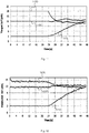
- the graph of Fig. 7 shows an example of a temporal cell throughput evolution.
- the reference power control implementation is employed with different target IoT's (3 dB, 12 dB, and 18 dB).
- Curve 710 denotes a target IoT of 3 dB.
- Curve 720 denotes a target IoT of 12 dB.
- Curve 730 denotes a target IoT of 18 dB.
- the self-optimizing power control implementation according to an embodiment is switched on. It is observed that, independent of the initial state, the cell performance converges to the same value. This is achieved after 44 sec, i.e. approximately 20 sec after the self-optimizing power control implementation has been switched on.
- Fig. 8 shows, for three different start conditions, an example evolution of the cell's worst mobile throughput.
- Curve 810 denotes a target IoT of 3 dB.
- Curve 820 denotes a target IoT of 12 dB.
- Curve 830 denotes a target IoT of 18 dB.
- Fig. 9 shows an example of a temporal evolution of each cell's performance (averaged in time). The different curves represent different cells. With the reference power control we observe that the performance is almost constant in time (Target IoT is 3dB). With an embodiment of the self-optimizing power control switched on we observe that each cell's performance is gradually improved.
- Fig. 10 shows the temporal evolution of each cell's worst mobile performance (averaged in time).
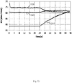
- Fig. 11 shows an example targeted IoT figure as function of time.
- Curve 1110 denotes a target IoT of 3 dB.
- Curve 1120 denotes a target IoT of 12 dB.
- Curve 1130 denotes a target IoT of 18 dB.
- Fig. 12 shows the temporal evolution of the measured IoT.
- Curve 1210 denotes a target IoT of 3 dB.
- Curve 1220 denotes a target IoT of 12 dB.
- Curve 1230 denotes a target IoT of 18 dB.
- Curve 13 shows the evolution of the target power-spectral density P 0 .
- Curve 1310 denotes a target IoT of 3 dB.
- Curve 1320 denotes a target IoT of 12 dB.
- Curve 1330 denotes a target IoT of 18 dB.
- Fig. 14 shows an example of a temporal evolution of each cell's performance (averaged in time) with an embodiment of self-optimizing power control switched on from the beginning.
- the system has been started with non-optimized power control parameters.
- the system achieves a stable, optimized configuration after approximately 24 seconds. All cells improved their performance.
- Fig. 15 shows the temporal evolution of each cell's worst mobile performance.
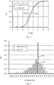
- Fig. 16 shows an example of a measured IOT distribution for both the reference power control 1610 and an embodiment of self-optimizing power control 1620.
- the target IoT in the reference power control case was 12 dB, a value, which has been identified close to optimum from a brute-force search. It is observed that the IoT distribution under self-optimizing power control is very similar to the reference case.
- Fig. 17 shows examples of target received power spectral density distributions ( P 0 ).
- the reference power control 1710 shows - as expected - a narrower P 0 distribution.
- the embodiment of self-optimizing power control 1720 shows a longer tails towards small and large P 0 values.
- embodiments introduce a concept that automatically determines optimum power control parameter values.
- the proposed concept uses an exchange of key-performance indicators, like the cell-edge user and cell throughput and statistical evaluation, to set new receive-power spectral densities ( P 0 ) and/or target interference-over-thermal (IoT) values. It has been shown that the proposed concept may always find - irrespective of the initial power control sate - an optimum set of power control parameters. Embodiments may be surprisingly fast compared to manual trial-and-error approach usually employed in conventional wireless networks.
- Functional blocks shall be understood as functional blocks comprising circuitry that is adapted for performing a certain function, respectively.
- a "means for s.th.” may as well be understood as a “means being adapted or suited for s.th.”.
- a means being adapted for performing a certain function does, hence, not imply that such means necessarily is performing said function (at a given time instant).
- any functional blocks may be provided through the use of dedicated hardware, such as “a processor”, “a controller”, etc. as well as hardware capable of executing software in association with appropriate software.
- any entity described herein as functional block may correspond to or be implemented as "one or more modules", “one or more devices”, “one or more units”, etc.
- the functions may be provided by a single dedicated processor, by a single shared processor, or by a plurality of individual processors, some of which may be shared.
- processor or “controller” should not be construed to refer exclusively to hardware capable of executing software, and may implicitly include, without limitation, digital signal processor (DSP) hardware, network processor, application specific integrated circuit (ASIC), field programmable gate array (FPGA), read only memory (ROM) for storing software, random access memory (RAM), and non-volatile storage.
- DSP digital signal processor
- ASIC application specific integrated circuit
- FPGA field programmable gate array
- ROM read only memory
- RAM random access memory
- non-volatile storage Other hardware, conventional and/or custom, may also be included.
- any block diagrams herein represent conceptual views of illustrative circuitry embodying the principles of the invention.
- any flow charts, flow diagrams, state transition diagrams, pseudo code, and the like represent various processes which may be substantially represented in computer readable medium and so executed by a computer or processor, whether or not such computer or processor is explicitly shown.
- each claim may stand on its own as a separate embodiment. While each claim may stand on its own as a separate embodiment, it is to be noted that - although a dependent claim may refer in the claims to a specific combination with one or more other claims - other embodiments may also include a combination of the dependent claim with the subject matter of each other dependent claim. Such combinations are proposed herein unless it is stated that a specific combination is not intended. Furthermore, it is intended to include also features of a claim to any other independent claim even if this claim is not directly made dependent to the independent claim.
- a single step may include or may be broken into multiple sub steps. Such sub steps may be included and part of the disclosure of this single step unless explicitly excluded.
Landscapes
- Engineering & Computer Science (AREA)
- Computer Networks & Wireless Communication (AREA)
- Signal Processing (AREA)
- Quality & Reliability (AREA)
- Mobile Radio Communication Systems (AREA)
Claims (15)
- Verfahren zur Sendeleistungseinstellung (400) für ein zellulares Kommunikationssystem (300), wobei das Verfahren zur Sendeleistungseinstellung (400) periodisch und unsynchronisiert zwischen verschiedenen Zellen des zellularen Kommunikationssystems (300) durchgeführt wird, wobei das Verfahren (400) Folgendes umfasst:Bestimmen (410), an einer Zelle (310-1), einer ersten Leistung (412; FOM1) der Zelle (310-1);Ändern (420), an der Zelle (310-1), eines Parameters zur Sendeleistungseinstellung in Aufwärtsrichtung (422; P0) für die Zelle, um die erste Leistung (412) zu maximieren;Bestimmen (430), an der Zelle (310-1), einer zweiten Leistung (432, FORM2) der einen oder mehreren Zellen (310-2) neben der Zelle (310-1); undÄndern (440), an der Zelle (310-1), eines Zielstörpegels (442; loT), um die zweite Leistung zu maximieren.
- Verfahren (400) nach Anspruch 1, wobei das Verfahren eine Vielzahl von Iterationen umfasst, wobei das Bestimmen (410) der ersten Leistung (412) in einer aktuellen Iteration Folgendes umfasst:Bestimmen eines ersten Werts (CE), der bezeichnend ist für einen Datendurchsatz eines zellenseitigen Benutzers, der der Zelle (310-1) seit einer vorherigen Iteration zugeordnet ist;Bestimmen eines zweiten Werts (C), der bezeichnend ist für den Datendurchsatz der Zelle seit der vorherigen Iteration; undBestimmen der ersten Leistung (412) basierend auf dem ersten Wert (CE) und dem zweiten Wert (C).
- Verfahren (400) nach Anspruch 2, wobei die erste Leistung (412) bestimmt wird gemäß

- Verfahren (400) nach Anspruch 1, wobei der Parameter zur Sendeleistungseinstellung in Aufwärtsrichtung (422; P0) ein Wert ist, der bezeichnend ist für eine Zielempfangsleistung an der Basisstation (312-1) der Zelle.
- Verfahren (400) nach Anspruch 4, wobei der Parameter zur Sendeleistungseinstellung in Aufwärtsrichtung (422; P0) Benutzern (314-1) gemeldet wird, die der Zelle (310-1) zugeordnet sind, und eine spektrale Empfangsleistungsdichte pro physikalischem Ressourcenblock bezeichnet.
- Verfahren (400) nach Anspruch 1, wobei das Ändern des Parameters zur Sendeleistungseinstellung in Aufwärtsrichtung (422; P0) in einer aktuellen Iteration des Verfahrens (400) zur Sendeleistungseinstellung das Erhöhen oder Verringern des Parameters zur Sendeleistungseinstellung in Aufwärtsrichtung (422; P0) um eine begrenzte Schrittgröße umfasst.
- Verfahren (400) nach Anspruch 1, wobei das Verfahren eine Vielzahl von Iterationen umfasst, wobei das Bestimmen der zweiten Leistung (432, FOM2) in einer aktuellen Iteration Folgendes umfasst:Bestimmen mindestens eines ersten Werts (CEi), der bezeichnend ist für einen Datendurchsatz eines zellenseitigen Benutzers, der mindestens einer benachbarten Zelle (310-2) seit einer vorherigen Iteration zugeordnet ist;Bestimmen mindestens eines zweiten Werts (Ci), der bezeichnend ist für den Datendurchsatz der mindestens einen benachbarten Zelle (310-2) seit der vorherigen Iteration; undBestimmen der zweiten Leistung (432, FOM2) basierend auf dem mindestens einen ersten Wert (CEi) und dem mindestens einen zweiten Wert (Ci).
- Verfahren (400) nach Anspruch 7, wobei die zweite Leistung (432, FOM2) bestimmt wird gemäß

- Verfahren (400) nach Anspruch 1, wobei der Zielstörpegel (442) bezeichnend ist für einen Interference-over-Thermal-"IoT"-Zielwert.
- Verfahren (400) nach Anspruch 1, wobei das Ändern des Zielstörpegels (442; loT) in einer aktuellen Iteration des Verfahrens zur Sendeleistungseinstellung das Erhöhen oder Verringern des Zielstörpegels (442; loT) um eine begrenzte Schrittgröße umfasst.
- Verfahren (400) nach Anspruch 1, wobei das Ändern des Zielstörpegels (442; IoT) das Verringern des Parameters zur Sendeleistungseinstellung in Aufwärtsrichtung (422; P0) in einer aktuellen Iteration des Verfahrens zur Sendeleistungseinstellung ausschließt, wenn der Zielstörpegel in der aktuellen Iteration erhöht wird.
- Verfahren (400) nach Anspruch 1, wobei die Zelle (310-1) eine Iteration des Verfahrens zu einem anderen Zeitpunkt durchführt als eine zweite Zelle (310-2).
- Verfahren (400) nach Anspruch 1, wobei das zellulare Kommunikationssystem (300) auf einem orthogonalen Frequenzmultiplex-Zugangsverfahren, OFDMA, und/oder Single-Carrier-Frequenzmultiplex-Zugangsverfahren, SC-FDMA, basiert.
- Computerprogramm mit einem Programmcode zum Durchführen des Verfahrens (400) nach Anspruch 1, wenn das Computerprogramm auf einer programmierbaren Hardware-Vorrichtung ausgeführt wird.
- Gerät zur Sendeleistungseinstellung für periodische und unsynchronisierte Sendeleistungseinstellung zwischen verschiedenen Zellen eines zellularen Kommunikationssystems (300), wobei das Gerät Folgendes umfasst:einen Prozessor, der ausgelegt ist zum Bestimmen, an einer Zelle (310-1), einer ersten Leistung (412; FOM1) der Zelle (310-1);einen Prozessor, der ausgelegt ist zum Ändern, an der Zelle (310-1), eines Parameters zur Sendeleistungseinstellung in Aufwärtsrichtung (422; P0) für die Zelle, um die erste Leistung (412; FOM1) zu maximieren;einen Prozessor, der ausgelegt ist zum Bestimmen, an der Zelle (310-1), einer zweiten Leistung (432, FOM2) der einen oder mehreren Zellen (310-2) neben der Zelle (310-1); undeinen Prozessor, der ausgelegt ist zum Ändern, an der Zelle (310-1), eines Zielstörpegels (442; loT), um die zweite Leistung (432, FOM2) zu maximieren.
Priority Applications (2)
| Application Number | Priority Date | Filing Date | Title |
|---|---|---|---|
| PL13306426T PL2863688T3 (pl) | 2013-10-17 | 2013-10-17 | Koncepcja sterowania mocą dla komórkowego komunikacyjnego systemu |
| EP13306426.1A EP2863688B1 (de) | 2013-10-17 | 2013-10-17 | Konzept für Sendeleistungseinstellung in einem zellularen Kommunikationsystem |
Applications Claiming Priority (1)
| Application Number | Priority Date | Filing Date | Title |
|---|---|---|---|
| EP13306426.1A EP2863688B1 (de) | 2013-10-17 | 2013-10-17 | Konzept für Sendeleistungseinstellung in einem zellularen Kommunikationsystem |
Publications (2)
| Publication Number | Publication Date |
|---|---|
| EP2863688A1 EP2863688A1 (de) | 2015-04-22 |
| EP2863688B1 true EP2863688B1 (de) | 2017-06-21 |
Family
ID=49518888
Family Applications (1)
| Application Number | Title | Priority Date | Filing Date |
|---|---|---|---|
| EP13306426.1A Not-in-force EP2863688B1 (de) | 2013-10-17 | 2013-10-17 | Konzept für Sendeleistungseinstellung in einem zellularen Kommunikationsystem |
Country Status (2)
| Country | Link |
|---|---|
| EP (1) | EP2863688B1 (de) |
| PL (1) | PL2863688T3 (de) |
Families Citing this family (1)
| Publication number | Priority date | Publication date | Assignee | Title |
|---|---|---|---|---|
| EP4013138A1 (de) * | 2020-12-10 | 2022-06-15 | Nokia Solutions and Networks Oy | Bestimmung von leistungsregelparametern mit offenem regelkreis |
Family Cites Families (2)
| Publication number | Priority date | Publication date | Assignee | Title |
|---|---|---|---|---|
| US8433359B2 (en) * | 2009-12-03 | 2013-04-30 | Intel Corporation | Uplink power control scheme |
| WO2012071727A1 (en) * | 2010-12-01 | 2012-06-07 | France Telecom Research & Development Beijing Company Limited | Method and local node for coordinated power allocation |
-
2013
- 2013-10-17 EP EP13306426.1A patent/EP2863688B1/de not_active Not-in-force
- 2013-10-17 PL PL13306426T patent/PL2863688T3/pl unknown
Also Published As
| Publication number | Publication date |
|---|---|
| EP2863688A1 (de) | 2015-04-22 |
| PL2863688T3 (pl) | 2017-10-31 |
Similar Documents
| Publication | Publication Date | Title |
|---|---|---|
| US10588096B2 (en) | Power control method and terminal device | |
| TWI699128B (zh) | 無線通訊系統中觸發多個路徑損耗參考的功率餘量報告的方法和設備 | |
| TWI707594B (zh) | 無線通訊系統中波束運作之功率餘量回報之方法及設備 | |
| CN104285479B (zh) | 用于优化lte中的上行功率控制参数的系统和方法 | |
| EP2501186B1 (de) | Leistungssteuerverfahren und entwickelter b-knoten | |
| CN109088663B (zh) | 一种用于功率调整的ue、基站中的方法和装置 | |
| US9414327B2 (en) | Method and apparatus of fractional power control in wireless communication networks | |
| WO2013008406A1 (ja) | 端末装置、基地局装置、送信方法及び受信方法 | |
| EP2991413A1 (de) | Verfahren und vorrichtung zur fraktionierten leistungssteuerung auf interferenzbasis | |
| CN104254121A (zh) | 一种pusch功率控制方法及装置 | |
| US9491711B2 (en) | Methods and nodes for multiple user MIMO scheduling and power control | |
| WO2011119075A1 (en) | Uplink load prediction using kalman filters | |
| US20150195842A1 (en) | Methods and Nodes for Multiple User MIMO Scheduling | |
| US9749965B2 (en) | Method for uplink fractional transmit power control | |
| US20170272970A1 (en) | Network node and a method performed thereby for congenstion control of a radio base station | |
| US20150358921A1 (en) | Fast Fading Power Restriction | |
| US20210099959A1 (en) | Deriving configured output powers with overlapping durations under uplink pre-emption | |
| WO2014119264A1 (ja) | 無線通信システム、無線局および上り送信電力制御方法 | |
| EP2915380B1 (de) | Drahtloses funknetzwerk und verfahren zur dpcch-leistungsverstärkung | |
| US20140288723A1 (en) | Filtering a Stream of Power Control Commands | |
| US9185661B2 (en) | Performing power control based on nominal packet size | |
| KR101659692B1 (ko) | 3gpp lte-a 이종망 환경에서 간섭 인식 기반 상향링크 전력제어 방법 및 시스템 | |
| EP3777356B1 (de) | Uplink-planung auf basis von oberen und unteren snr-zielen | |
| EP2863688B1 (de) | Konzept für Sendeleistungseinstellung in einem zellularen Kommunikationsystem | |
| US20150117407A1 (en) | Adapting Uplink Transmissions in a Wireless Telecommunications Network |
Legal Events
| Date | Code | Title | Description |
|---|---|---|---|
| PUAI | Public reference made under article 153(3) epc to a published international application that has entered the european phase |
Free format text: ORIGINAL CODE: 0009012 |
|
| 17P | Request for examination filed |
Effective date: 20141009 |
|
| AK | Designated contracting states |
Kind code of ref document: A1 Designated state(s): AL AT BE BG CH CY CZ DE DK EE ES FI FR GB GR HR HU IE IS IT LI LT LU LV MC MK MT NL NO PL PT RO RS SE SI SK SM TR |
|
| AX | Request for extension of the european patent |
Extension state: BA ME |
|
| RBV | Designated contracting states (corrected) |
Designated state(s): AL AT BE BG CH CY CZ DE DK EE ES FI FR GB GR HR HU IE IS IT LI LT LU LV MC MK MT NL NO PL PT RO RS SE SI SK SM TR |
|
| 17Q | First examination report despatched |
Effective date: 20160421 |
|
| STAA | Information on the status of an ep patent application or granted ep patent |
Free format text: STATUS: EXAMINATION IS IN PROGRESS |
|
| REG | Reference to a national code |
Ref country code: DE Ref legal event code: R079 Ref document number: 602013022509 Country of ref document: DE Free format text: PREVIOUS MAIN CLASS: H04W0052140000 Ipc: H04W0052100000 |
|
| GRAP | Despatch of communication of intention to grant a patent |
Free format text: ORIGINAL CODE: EPIDOSNIGR1 |
|
| STAA | Information on the status of an ep patent application or granted ep patent |
Free format text: STATUS: GRANT OF PATENT IS INTENDED |
|
| RIC1 | Information provided on ipc code assigned before grant |
Ipc: H04W 92/20 20090101ALI20170112BHEP Ipc: H04W 52/36 20090101ALI20170112BHEP Ipc: H04W 52/26 20090101ALI20170112BHEP Ipc: H04W 52/24 20090101ALI20170112BHEP Ipc: H04W 52/40 20090101ALI20170112BHEP Ipc: H04W 28/18 20090101ALI20170112BHEP Ipc: H04W 52/10 20090101AFI20170112BHEP Ipc: H04W 52/14 20090101ALI20170112BHEP Ipc: H04W 52/22 20090101ALI20170112BHEP |
|
| INTG | Intention to grant announced |
Effective date: 20170127 |
|
| GRAS | Grant fee paid |
Free format text: ORIGINAL CODE: EPIDOSNIGR3 |
|
| GRAA | (expected) grant |
Free format text: ORIGINAL CODE: 0009210 |
|
| STAA | Information on the status of an ep patent application or granted ep patent |
Free format text: STATUS: THE PATENT HAS BEEN GRANTED |
|
| AK | Designated contracting states |
Kind code of ref document: B1 Designated state(s): AL AT BE BG CH CY CZ DE DK EE ES FI FR GB GR HR HU IE IS IT LI LT LU LV MC MK MT NL NO PL PT RO RS SE SI SK SM TR |
|
| REG | Reference to a national code |
Ref country code: GB Ref legal event code: FG4D |
|
| REG | Reference to a national code |
Ref country code: CH Ref legal event code: EP |
|
| REG | Reference to a national code |
Ref country code: IE Ref legal event code: FG4D |
|
| REG | Reference to a national code |
Ref country code: AT Ref legal event code: REF Ref document number: 903936 Country of ref document: AT Kind code of ref document: T Effective date: 20170715 |
|
| REG | Reference to a national code |
Ref country code: DE Ref legal event code: R096 Ref document number: 602013022509 Country of ref document: DE |
|
| REG | Reference to a national code |
Ref country code: NL Ref legal event code: FP |
|
| REG | Reference to a national code |
Ref country code: FR Ref legal event code: PLFP Year of fee payment: 5 |
|
| PG25 | Lapsed in a contracting state [announced via postgrant information from national office to epo] |
Ref country code: FI Free format text: LAPSE BECAUSE OF FAILURE TO SUBMIT A TRANSLATION OF THE DESCRIPTION OR TO PAY THE FEE WITHIN THE PRESCRIBED TIME-LIMIT Effective date: 20170621 Ref country code: NO Free format text: LAPSE BECAUSE OF FAILURE TO SUBMIT A TRANSLATION OF THE DESCRIPTION OR TO PAY THE FEE WITHIN THE PRESCRIBED TIME-LIMIT Effective date: 20170921 Ref country code: LT Free format text: LAPSE BECAUSE OF FAILURE TO SUBMIT A TRANSLATION OF THE DESCRIPTION OR TO PAY THE FEE WITHIN THE PRESCRIBED TIME-LIMIT Effective date: 20170621 Ref country code: HR Free format text: LAPSE BECAUSE OF FAILURE TO SUBMIT A TRANSLATION OF THE DESCRIPTION OR TO PAY THE FEE WITHIN THE PRESCRIBED TIME-LIMIT Effective date: 20170621 Ref country code: GR Free format text: LAPSE BECAUSE OF FAILURE TO SUBMIT A TRANSLATION OF THE DESCRIPTION OR TO PAY THE FEE WITHIN THE PRESCRIBED TIME-LIMIT Effective date: 20170922 |
|
| REG | Reference to a national code |
Ref country code: LT Ref legal event code: MG4D |
|
| REG | Reference to a national code |
Ref country code: AT Ref legal event code: MK05 Ref document number: 903936 Country of ref document: AT Kind code of ref document: T Effective date: 20170621 |
|
| PG25 | Lapsed in a contracting state [announced via postgrant information from national office to epo] |
Ref country code: LV Free format text: LAPSE BECAUSE OF FAILURE TO SUBMIT A TRANSLATION OF THE DESCRIPTION OR TO PAY THE FEE WITHIN THE PRESCRIBED TIME-LIMIT Effective date: 20170621 Ref country code: RS Free format text: LAPSE BECAUSE OF FAILURE TO SUBMIT A TRANSLATION OF THE DESCRIPTION OR TO PAY THE FEE WITHIN THE PRESCRIBED TIME-LIMIT Effective date: 20170621 Ref country code: BG Free format text: LAPSE BECAUSE OF FAILURE TO SUBMIT A TRANSLATION OF THE DESCRIPTION OR TO PAY THE FEE WITHIN THE PRESCRIBED TIME-LIMIT Effective date: 20170921 Ref country code: SE Free format text: LAPSE BECAUSE OF FAILURE TO SUBMIT A TRANSLATION OF THE DESCRIPTION OR TO PAY THE FEE WITHIN THE PRESCRIBED TIME-LIMIT Effective date: 20170621 |
|
| PG25 | Lapsed in a contracting state [announced via postgrant information from national office to epo] |
Ref country code: SK Free format text: LAPSE BECAUSE OF FAILURE TO SUBMIT A TRANSLATION OF THE DESCRIPTION OR TO PAY THE FEE WITHIN THE PRESCRIBED TIME-LIMIT Effective date: 20170621 Ref country code: EE Free format text: LAPSE BECAUSE OF FAILURE TO SUBMIT A TRANSLATION OF THE DESCRIPTION OR TO PAY THE FEE WITHIN THE PRESCRIBED TIME-LIMIT Effective date: 20170621 Ref country code: CZ Free format text: LAPSE BECAUSE OF FAILURE TO SUBMIT A TRANSLATION OF THE DESCRIPTION OR TO PAY THE FEE WITHIN THE PRESCRIBED TIME-LIMIT Effective date: 20170621 Ref country code: RO Free format text: LAPSE BECAUSE OF FAILURE TO SUBMIT A TRANSLATION OF THE DESCRIPTION OR TO PAY THE FEE WITHIN THE PRESCRIBED TIME-LIMIT Effective date: 20170621 Ref country code: AT Free format text: LAPSE BECAUSE OF FAILURE TO SUBMIT A TRANSLATION OF THE DESCRIPTION OR TO PAY THE FEE WITHIN THE PRESCRIBED TIME-LIMIT Effective date: 20170621 |
|
| PG25 | Lapsed in a contracting state [announced via postgrant information from national office to epo] |
Ref country code: IS Free format text: LAPSE BECAUSE OF FAILURE TO SUBMIT A TRANSLATION OF THE DESCRIPTION OR TO PAY THE FEE WITHIN THE PRESCRIBED TIME-LIMIT Effective date: 20171021 Ref country code: IT Free format text: LAPSE BECAUSE OF FAILURE TO SUBMIT A TRANSLATION OF THE DESCRIPTION OR TO PAY THE FEE WITHIN THE PRESCRIBED TIME-LIMIT Effective date: 20170621 Ref country code: ES Free format text: LAPSE BECAUSE OF FAILURE TO SUBMIT A TRANSLATION OF THE DESCRIPTION OR TO PAY THE FEE WITHIN THE PRESCRIBED TIME-LIMIT Effective date: 20170621 Ref country code: SM Free format text: LAPSE BECAUSE OF FAILURE TO SUBMIT A TRANSLATION OF THE DESCRIPTION OR TO PAY THE FEE WITHIN THE PRESCRIBED TIME-LIMIT Effective date: 20170621 |
|
| REG | Reference to a national code |
Ref country code: DE Ref legal event code: R097 Ref document number: 602013022509 Country of ref document: DE |
|
| REG | Reference to a national code |
Ref country code: CH Ref legal event code: PCOW Free format text: NEW ADDRESS: SITE NOKIA PARIS SACLAY ROUTE DE VILLEJUST, 91620 NOZAY (FR) |
|
| RAP2 | Party data changed (patent owner data changed or rights of a patent transferred) |
Owner name: ALCATEL LUCENT |
|
| PLBE | No opposition filed within time limit |
Free format text: ORIGINAL CODE: 0009261 |
|
| STAA | Information on the status of an ep patent application or granted ep patent |
Free format text: STATUS: NO OPPOSITION FILED WITHIN TIME LIMIT |
|
| PG25 | Lapsed in a contracting state [announced via postgrant information from national office to epo] |
Ref country code: DK Free format text: LAPSE BECAUSE OF FAILURE TO SUBMIT A TRANSLATION OF THE DESCRIPTION OR TO PAY THE FEE WITHIN THE PRESCRIBED TIME-LIMIT Effective date: 20170621 |
|
| 26N | No opposition filed |
Effective date: 20180322 |
|
| PG25 | Lapsed in a contracting state [announced via postgrant information from national office to epo] |
Ref country code: MC Free format text: LAPSE BECAUSE OF FAILURE TO SUBMIT A TRANSLATION OF THE DESCRIPTION OR TO PAY THE FEE WITHIN THE PRESCRIBED TIME-LIMIT Effective date: 20170621 |
|
| REG | Reference to a national code |
Ref country code: CH Ref legal event code: PL |
|
| REG | Reference to a national code |
Ref country code: IE Ref legal event code: MM4A |
|
| PG25 | Lapsed in a contracting state [announced via postgrant information from national office to epo] |
Ref country code: LI Free format text: LAPSE BECAUSE OF NON-PAYMENT OF DUE FEES Effective date: 20171031 Ref country code: CH Free format text: LAPSE BECAUSE OF NON-PAYMENT OF DUE FEES Effective date: 20171031 Ref country code: LU Free format text: LAPSE BECAUSE OF NON-PAYMENT OF DUE FEES Effective date: 20171017 |
|
| REG | Reference to a national code |
Ref country code: BE Ref legal event code: MM Effective date: 20171031 |
|
| PG25 | Lapsed in a contracting state [announced via postgrant information from national office to epo] |
Ref country code: BE Free format text: LAPSE BECAUSE OF NON-PAYMENT OF DUE FEES Effective date: 20171031 Ref country code: SI Free format text: LAPSE BECAUSE OF FAILURE TO SUBMIT A TRANSLATION OF THE DESCRIPTION OR TO PAY THE FEE WITHIN THE PRESCRIBED TIME-LIMIT Effective date: 20170621 |
|
| REG | Reference to a national code |
Ref country code: FR Ref legal event code: PLFP Year of fee payment: 6 |
|
| PG25 | Lapsed in a contracting state [announced via postgrant information from national office to epo] |
Ref country code: MT Free format text: LAPSE BECAUSE OF NON-PAYMENT OF DUE FEES Effective date: 20171017 |
|
| PG25 | Lapsed in a contracting state [announced via postgrant information from national office to epo] |
Ref country code: IE Free format text: LAPSE BECAUSE OF NON-PAYMENT OF DUE FEES Effective date: 20171017 |
|
| PGFP | Annual fee paid to national office [announced via postgrant information from national office to epo] |
Ref country code: FR Payment date: 20180913 Year of fee payment: 6 |
|
| PGFP | Annual fee paid to national office [announced via postgrant information from national office to epo] |
Ref country code: PL Payment date: 20180917 Year of fee payment: 6 |
|
| PGFP | Annual fee paid to national office [announced via postgrant information from national office to epo] |
Ref country code: NL Payment date: 20181017 Year of fee payment: 6 |
|
| PGFP | Annual fee paid to national office [announced via postgrant information from national office to epo] |
Ref country code: DE Payment date: 20181002 Year of fee payment: 6 |
|
| PGFP | Annual fee paid to national office [announced via postgrant information from national office to epo] |
Ref country code: GB Payment date: 20181017 Year of fee payment: 6 |
|
| PG25 | Lapsed in a contracting state [announced via postgrant information from national office to epo] |
Ref country code: HU Free format text: LAPSE BECAUSE OF FAILURE TO SUBMIT A TRANSLATION OF THE DESCRIPTION OR TO PAY THE FEE WITHIN THE PRESCRIBED TIME-LIMIT; INVALID AB INITIO Effective date: 20131017 |
|
| PG25 | Lapsed in a contracting state [announced via postgrant information from national office to epo] |
Ref country code: CY Free format text: LAPSE BECAUSE OF FAILURE TO SUBMIT A TRANSLATION OF THE DESCRIPTION OR TO PAY THE FEE WITHIN THE PRESCRIBED TIME-LIMIT Effective date: 20170621 |
|
| PG25 | Lapsed in a contracting state [announced via postgrant information from national office to epo] |
Ref country code: MK Free format text: LAPSE BECAUSE OF FAILURE TO SUBMIT A TRANSLATION OF THE DESCRIPTION OR TO PAY THE FEE WITHIN THE PRESCRIBED TIME-LIMIT Effective date: 20170621 |
|
| PG25 | Lapsed in a contracting state [announced via postgrant information from national office to epo] |
Ref country code: TR Free format text: LAPSE BECAUSE OF FAILURE TO SUBMIT A TRANSLATION OF THE DESCRIPTION OR TO PAY THE FEE WITHIN THE PRESCRIBED TIME-LIMIT Effective date: 20170621 |
|
| REG | Reference to a national code |
Ref country code: DE Ref legal event code: R119 Ref document number: 602013022509 Country of ref document: DE |
|
| PG25 | Lapsed in a contracting state [announced via postgrant information from national office to epo] |
Ref country code: PT Free format text: LAPSE BECAUSE OF FAILURE TO SUBMIT A TRANSLATION OF THE DESCRIPTION OR TO PAY THE FEE WITHIN THE PRESCRIBED TIME-LIMIT Effective date: 20170621 |
|
| REG | Reference to a national code |
Ref country code: NL Ref legal event code: MM Effective date: 20191101 |
|
| PG25 | Lapsed in a contracting state [announced via postgrant information from national office to epo] |
Ref country code: AL Free format text: LAPSE BECAUSE OF FAILURE TO SUBMIT A TRANSLATION OF THE DESCRIPTION OR TO PAY THE FEE WITHIN THE PRESCRIBED TIME-LIMIT Effective date: 20170621 Ref country code: DE Free format text: LAPSE BECAUSE OF NON-PAYMENT OF DUE FEES Effective date: 20200501 |
|
| PG25 | Lapsed in a contracting state [announced via postgrant information from national office to epo] |
Ref country code: NL Free format text: LAPSE BECAUSE OF NON-PAYMENT OF DUE FEES Effective date: 20191101 |
|
| GBPC | Gb: european patent ceased through non-payment of renewal fee |
Effective date: 20191017 |
|
| PG25 | Lapsed in a contracting state [announced via postgrant information from national office to epo] |
Ref country code: FR Free format text: LAPSE BECAUSE OF NON-PAYMENT OF DUE FEES Effective date: 20191031 Ref country code: GB Free format text: LAPSE BECAUSE OF NON-PAYMENT OF DUE FEES Effective date: 20191017 |
|
| PG25 | Lapsed in a contracting state [announced via postgrant information from national office to epo] |
Ref country code: PL Free format text: LAPSE BECAUSE OF NON-PAYMENT OF DUE FEES Effective date: 20191017 |