EP2863706A1 - Élément de contact - Google Patents
Élément de contact Download PDFInfo
- Publication number
- EP2863706A1 EP2863706A1 EP20140003546 EP14003546A EP2863706A1 EP 2863706 A1 EP2863706 A1 EP 2863706A1 EP 20140003546 EP20140003546 EP 20140003546 EP 14003546 A EP14003546 A EP 14003546A EP 2863706 A1 EP2863706 A1 EP 2863706A1
- Authority
- EP
- European Patent Office
- Prior art keywords
- coil
- capacitor
- contact element
- motor vehicle
- carrier element
- Prior art date
- Legal status (The legal status is an assumption and is not a legal conclusion. Google has not performed a legal analysis and makes no representation as to the accuracy of the status listed.)
- Withdrawn
Links
- 239000003990 capacitor Substances 0.000 claims abstract description 43
- 238000010438 heat treatment Methods 0.000 claims abstract description 10
- 239000000853 adhesive Substances 0.000 claims description 3
- 230000001070 adhesive effect Effects 0.000 claims description 3
- 239000000463 material Substances 0.000 claims description 2
- 238000009413 insulation Methods 0.000 claims 1
- 230000000903 blocking effect Effects 0.000 description 4
- 239000011248 coating agent Substances 0.000 description 4
- 238000000576 coating method Methods 0.000 description 4
- 239000004020 conductor Substances 0.000 description 3
- 229910052751 metal Inorganic materials 0.000 description 3
- 239000002184 metal Substances 0.000 description 3
- 230000001629 suppression Effects 0.000 description 3
- 229910000679 solder Inorganic materials 0.000 description 2
- BQCADISMDOOEFD-UHFFFAOYSA-N Silver Chemical compound [Ag] BQCADISMDOOEFD-UHFFFAOYSA-N 0.000 description 1
- 238000011109 contamination Methods 0.000 description 1
- 238000002788 crimping Methods 0.000 description 1
- 230000000694 effects Effects 0.000 description 1
- 238000005538 encapsulation Methods 0.000 description 1
- 238000001914 filtration Methods 0.000 description 1
- 239000012212 insulator Substances 0.000 description 1
- 239000012811 non-conductive material Substances 0.000 description 1
- 229910052709 silver Inorganic materials 0.000 description 1
- 239000004332 silver Substances 0.000 description 1
- 238000005476 soldering Methods 0.000 description 1
- 125000006850 spacer group Chemical group 0.000 description 1
- 229910000859 α-Fe Inorganic materials 0.000 description 1
Images


Classifications
-
- H—ELECTRICITY
- H01—ELECTRIC ELEMENTS
- H01Q—ANTENNAS, i.e. RADIO AERIALS
- H01Q1/00—Details of, or arrangements associated with, antennas
- H01Q1/52—Means for reducing coupling between antennas; Means for reducing coupling between an antenna and another structure
-
- H—ELECTRICITY
- H01—ELECTRIC ELEMENTS
- H01Q—ANTENNAS, i.e. RADIO AERIALS
- H01Q1/00—Details of, or arrangements associated with, antennas
- H01Q1/12—Supports; Mounting means
- H01Q1/1271—Supports; Mounting means for mounting on windscreens
- H01Q1/1278—Supports; Mounting means for mounting on windscreens in association with heating wires or layers
-
- H—ELECTRICITY
- H04—ELECTRIC COMMUNICATION TECHNIQUE
- H04B—TRANSMISSION
- H04B15/00—Suppression or limitation of noise or interference
- H04B15/02—Reducing interference from electric apparatus by means located at or near the interfering apparatus
-
- H—ELECTRICITY
- H05—ELECTRIC TECHNIQUES NOT OTHERWISE PROVIDED FOR
- H05B—ELECTRIC HEATING; ELECTRIC LIGHT SOURCES NOT OTHERWISE PROVIDED FOR; CIRCUIT ARRANGEMENTS FOR ELECTRIC LIGHT SOURCES, IN GENERAL
- H05B3/00—Ohmic-resistance heating
- H05B3/02—Details
- H05B3/06—Heater elements structurally combined with coupling elements or holders
-
- H—ELECTRICITY
- H05—ELECTRIC TECHNIQUES NOT OTHERWISE PROVIDED FOR
- H05B—ELECTRIC HEATING; ELECTRIC LIGHT SOURCES NOT OTHERWISE PROVIDED FOR; CIRCUIT ARRANGEMENTS FOR ELECTRIC LIGHT SOURCES, IN GENERAL
- H05B3/00—Ohmic-resistance heating
- H05B3/84—Heating arrangements specially adapted for transparent or reflecting areas, e.g. for demisting or de-icing windows, mirrors or vehicle windshields
-
- H—ELECTRICITY
- H05—ELECTRIC TECHNIQUES NOT OTHERWISE PROVIDED FOR
- H05B—ELECTRIC HEATING; ELECTRIC LIGHT SOURCES NOT OTHERWISE PROVIDED FOR; CIRCUIT ARRANGEMENTS FOR ELECTRIC LIGHT SOURCES, IN GENERAL
- H05B2203/00—Aspects relating to Ohmic resistive heating covered by group H05B3/00
- H05B2203/016—Heaters using particular connecting means
Definitions
- the invention relates to a contact element for the connection of motor vehicle window heatings with the motor vehicle electrical system according to the preamble of claim 1.
- the heaters for vehicle windows which are customary in particular in rear windows, realized by a partial metal coating of the disk surface, for example by a silver print.
- the partial coating of the disk surface forms a network of conductor tracks, which are heated by the current flow, which results when an electrical voltage is applied thereto, and thus heat the disk.
- special contact elements are necessary, which allow an electrically conductive connection between the metal coating of the disc and a conventional electrical connection element, such as a cable.
- these contact elements are contacted with cables, which lead to the electrical system or serving as a ground connection body. It is regularly necessary to interpose between the rear window heating and the electrical system or the vehicle electrical system or the body of a coil for the purpose of suppression.
- a corresponding contact element is known in which such a coil directly on at the contact element between the two for connection to the vehicle window heating and / or the vehicle window provided mounting areas is arranged.
- Disk heaters so in the context of the invention essentially meant in or on the vehicle window or applied printed conductors are also used as an integrated broadcast antenna. Due to the increasing number of electrical components of a motor vehicle, interference signals in the HF range occur, in particular of these components, which considerably impair the function of an integrated broadcasting antenna.
- an HF filter is used by accommodating a suitable filter module at a suitable location away from the pane and from there drawing a connecting line to the contact element.
- connection line to the filter module in turn acts as a receiving antenna and thus can receive interference, which in turn interfere with the operation of the broadcast antenna.
- the invention is therefore based on the object to provide a contact element of the type mentioned, with which the disturbing influence of RF signals on the functioning of broadcast antennas can be reduced or even prevented.
- the contact element according to the invention has a carrier element and a coil attached thereto, wherein a first end of the coil with the carrier element electrically conductive connected is.
- the second end of the coil is electrically connectable to a motor vehicle electrical system.
- the carrier element has at least one fastening region which can be fastened to a motor vehicle window and / or a motor vehicle window heating element.
- the carrier element can be electrically connected to the vehicle window heating element via the at least one fastening region.
- the contact element has a capacitor arranged or connected in parallel with the coil, the first terminal of which is electrically conductively connected to the first end of the coil, which may be a cylindrical coil, and the second terminal of which is connected to a motor vehicle electrical system, in particular the ground terminal thereof.
- the carrier element and the first end of the coil and / or the first terminal of the capacitor are connected by a crimp connection, welded connection or solder connection.
- the sheathing element is preferably a heat-shrinkable tube, in particular an adhesive heat-shrinkable tube, or shells, in particular Half shells made of plastic, or an encapsulation made of plastic material.
- an insulating element may be arranged between the components carrier element and / or coil and / or capacitor.
- the coil is preferably arranged with its axis parallel to the main extension direction of the carrier element.
- the capacitor may in particular be a capacitor in radial or axial design, in particular a LOW ESR capacitor.
- the LOW ESR capacitor has a low internal resistance. Consequently, it is possible to operate the contact element according to the invention with only lower heat development, which is synonymous with a longer life.
- the condenser preferably has a cylindrical shape. Particularly space-saving and saving cable length can then be provided that the capacitor is arranged with its axis parallel to the main extension direction of the support element.
- the capacitor is designed as a radial capacitor. In this way, the connections can be kept very short.
- the second terminal of the capacitor which is not connected to the coil, to be connected to a connecting line which is led out of the contact element in the opposite direction terminal and fixed by the sheathing element, in particular on the capacitor.
- a strain relief of the second terminal contact of the capacitor can be achieved by the connected to the terminal of the capacitor line, in particular for grounding can be used, is fixed to the contact element by the sheath, so that they can not move under tensile load. This can be done in particular by fixing by means of a shrink tube.
- Contact element shown has the two mounting portions 1a and 1b, which are equipped with solder deposits 8. Between the attachment regions 1a, 1b extends along the main extension direction X of the carrier element 1, the region 1c, which by the angled portions 9 (see. Fig. 3 ) of the carrier element 1 of the vehicle window (see Pos. 40 in Fig. 5 ) is spaced.
- the coil 2 preferably has a core of ferrite, but in principle the use of coreless coils is also possible.
- the coil 2 is with its end 2a electrically connected via the connection 6 with the carrier element 1.
- a parallel to the coil 2 arranged capacitor 20 which is in the example shown, a radial capacitor with a cylindrical shape, which also extends with its longitudinal axis parallel to the main extension direction X.
- the one contact 21 of the capacitor 20 is connected to the end 2a of the coil 2 and the carrier element 1 in the region of the attachment region 1a.
- the other terminal contact 22 of the capacitor 20 is connected to a line 30, which is bent out in the region of the terminal 22 by 180 ° in the region of the mounting region 1b out of the contact element.
- the connection contacts or legs of the capacitor are arranged in a V-shape running apart from one another.
- the coil 2 is fed by the line 10, which is connectable to the electrical supply system of a vehicle.
- the carrier element 1, the coil 2 and the capacitor 20 are surrounded by a sheath element (not shown), preferably by a (preferably adhesive) heat-shrinkable tube.
- a sheath element not shown
- the line 30 is pressed against the capacitor, so that it is immobile by this frictional connection and for the capacitor contact 22, and the connecting piece 7 of the line 30 is a strain relief.
- an insulator or spacer element 4 may be provided between current-conducting components, which consists of an electrically non-conductive material and in the example shown between the carrier element 1 and the components lying in parallel coil 2 and capacitor 20 is located.
- connection between the components coil 2 and capacitor 20 with each other and the carrier element 1 can take place in various ways, e.g. by plugging, soldering or crimping.
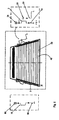
- FIG. 5 the attachment and interconnection of the contact element to a motor vehicle panel 40 according to the invention is shown.
- a disk heater 50 is provided of conductor tracks, which has at the edge regions for filtering and / or energization terminal contact fields.
- To such a contact element according to the invention is mounted, which is seen as in the right circuit, is connected and contacted via the mounting portion 1a with the disk heater 50.
- Capacitor 20 and coil 2 are connected at one end to the mounting portion 1a. The other coil end is connected to a voltage source U. Parallel to coil 2, the capacitor 20 is connected and connected via the line 30 to the ground potential.
- a coil assembly with a suppression coil 70 which is connected via the connection portion 80 with the disk heater 50 and via the line 60 to the ground.
Landscapes
- Engineering & Computer Science (AREA)
- Computer Networks & Wireless Communication (AREA)
- Signal Processing (AREA)
- Air-Conditioning For Vehicles (AREA)
Applications Claiming Priority (1)
| Application Number | Priority Date | Filing Date | Title |
|---|---|---|---|
| DE201320009240 DE202013009240U1 (de) | 2013-10-18 | 2013-10-18 | Kontaktelement |
Publications (1)
| Publication Number | Publication Date |
|---|---|
| EP2863706A1 true EP2863706A1 (fr) | 2015-04-22 |
Family
ID=49754489
Family Applications (1)
| Application Number | Title | Priority Date | Filing Date |
|---|---|---|---|
| EP20140003546 Withdrawn EP2863706A1 (fr) | 2013-10-18 | 2014-10-16 | Élément de contact |
Country Status (2)
| Country | Link |
|---|---|
| EP (1) | EP2863706A1 (fr) |
| DE (1) | DE202013009240U1 (fr) |
Cited By (1)
| Publication number | Priority date | Publication date | Assignee | Title |
|---|---|---|---|---|
| CN115588556A (zh) * | 2021-07-06 | 2023-01-10 | Few汽车电器厂有限责任两合公司 | 用于插接线圈元件的壳体、插接线圈元件和窗玻璃 |
Citations (4)
| Publication number | Priority date | Publication date | Assignee | Title |
|---|---|---|---|---|
| EP0355424A2 (fr) * | 1988-07-25 | 1990-02-28 | Asahi Glass Company Ltd. | Antenne sur vitre d'un véhicule |
| JP2000013166A (ja) * | 1998-06-23 | 2000-01-14 | Matsushita Electric Ind Co Ltd | 自動車ガラスアンテナ用フィルタ装置 |
| EP1555865A2 (fr) * | 2004-01-14 | 2005-07-20 | MD Elektronik GmbH | Assemblage d'un circuit bouchon avec des composants électroniques discrets et passifs |
| DE202011109444U1 (de) | 2011-12-23 | 2012-02-01 | Elektrobau Heinz Meissner Gmbh & Co. Kg | Kontaktelement |
-
2013
- 2013-10-18 DE DE201320009240 patent/DE202013009240U1/de not_active Expired - Lifetime
-
2014
- 2014-10-16 EP EP20140003546 patent/EP2863706A1/fr not_active Withdrawn
Patent Citations (4)
| Publication number | Priority date | Publication date | Assignee | Title |
|---|---|---|---|---|
| EP0355424A2 (fr) * | 1988-07-25 | 1990-02-28 | Asahi Glass Company Ltd. | Antenne sur vitre d'un véhicule |
| JP2000013166A (ja) * | 1998-06-23 | 2000-01-14 | Matsushita Electric Ind Co Ltd | 自動車ガラスアンテナ用フィルタ装置 |
| EP1555865A2 (fr) * | 2004-01-14 | 2005-07-20 | MD Elektronik GmbH | Assemblage d'un circuit bouchon avec des composants électroniques discrets et passifs |
| DE202011109444U1 (de) | 2011-12-23 | 2012-02-01 | Elektrobau Heinz Meissner Gmbh & Co. Kg | Kontaktelement |
Cited By (1)
| Publication number | Priority date | Publication date | Assignee | Title |
|---|---|---|---|---|
| CN115588556A (zh) * | 2021-07-06 | 2023-01-10 | Few汽车电器厂有限责任两合公司 | 用于插接线圈元件的壳体、插接线圈元件和窗玻璃 |
Also Published As
| Publication number | Publication date |
|---|---|
| DE202013009240U1 (de) | 2013-11-08 |
Similar Documents
| Publication | Publication Date | Title |
|---|---|---|
| EP3925071B1 (fr) | Module de filtre de réduction du bruit en mode commun et différentiel et procédé de fabrication d'un tel module de filtre | |
| EP0800228B1 (fr) | Amplificateur d'antenne sur un carreau de fenêtre | |
| DE102012218847A1 (de) | Anschlusselement für eine Antriebsanordnung sowie eine Antriebsanordnung mit einem Anschlussteil | |
| EP3340444A2 (fr) | Moteur électrique et module de ventilateur de radiateur pourvu d'un tel moteur électrique | |
| EP3080872B1 (fr) | Liaison de contact de lignes de données blindées à une carte de circuits et procédé de mise en contact d'une pluralité de lignes de données blindées avec une carte de circuits | |
| EP1976075B1 (fr) | Adaptateur | |
| EP3206258B1 (fr) | Système de fabrication d'un raccordement électrique, raccordement électrique et son procédé de fabrication | |
| EP1555865B1 (fr) | Assemblage d'un circuit bouchon avec des composants électroniques discrets et passifs | |
| EP1993877B1 (fr) | Dispositif de liaison pour la transmission de courant electrique, notamment pour un chauffage de volant de direction d'un vehicule | |
| DE202008014542U1 (de) | Steckverbinder für Schaltungsplatinen | |
| DE3308492A1 (de) | Mehrpolige steckverbindung | |
| DE202013010951U1 (de) | Baugruppe zur Leiterplattenbestückung | |
| DE202013009240U1 (de) | Kontaktelement | |
| DE202011109444U1 (de) | Kontaktelement | |
| EP3192155B1 (fr) | Moteur électrique pourvu de composants cms et élément de liaison associé | |
| DE202013010545U1 (de) | Elektrisches Kontaktelement | |
| EP3627634B1 (fr) | Connecteur enfichable électrique pour un câble électrique multi-fils | |
| EP2425498B1 (fr) | Système de liaison pour une carte de circuit imprimé | |
| WO2006048233A1 (fr) | Capteur de courant de batterie pour vehicule automobile | |
| EP3448135A1 (fr) | Fiche, douille enfichable et système de raccord correspondant | |
| EP2194613B1 (fr) | Agencement de rails conducteurs | |
| EP1480290B1 (fr) | Dispositif de contact avec un fil de connexion | |
| WO2024046633A1 (fr) | Ensemble filtrant | |
| DE102025113741A1 (de) | Rauschfilter und kabelbaum | |
| EP1855512B1 (fr) | Assemblage d'un support de circuit et d'un support de contact tenu à distance fixe de celui-ci |
Legal Events
| Date | Code | Title | Description |
|---|---|---|---|
| PUAI | Public reference made under article 153(3) epc to a published international application that has entered the european phase |
Free format text: ORIGINAL CODE: 0009012 |
|
| 17P | Request for examination filed |
Effective date: 20141016 |
|
| AK | Designated contracting states |
Kind code of ref document: A1 Designated state(s): AL AT BE BG CH CY CZ DE DK EE ES FI FR GB GR HR HU IE IS IT LI LT LU LV MC MK MT NL NO PL PT RO RS SE SI SK SM TR |
|
| AX | Request for extension of the european patent |
Extension state: BA ME |
|
| STAA | Information on the status of an ep patent application or granted ep patent |
Free format text: STATUS: THE APPLICATION IS DEEMED TO BE WITHDRAWN |
|
| 18D | Application deemed to be withdrawn |
Effective date: 20151023 |