EP2863777B1 - Maschine mit verschiebbarer tropfenschale zur zubereitung von getränken mittels infusion - Google Patents
Maschine mit verschiebbarer tropfenschale zur zubereitung von getränken mittels infusion Download PDFInfo
- Publication number
- EP2863777B1 EP2863777B1 EP13730915.9A EP13730915A EP2863777B1 EP 2863777 B1 EP2863777 B1 EP 2863777B1 EP 13730915 A EP13730915 A EP 13730915A EP 2863777 B1 EP2863777 B1 EP 2863777B1
- Authority
- EP
- European Patent Office
- Prior art keywords
- machine
- drip tray
- basin
- bassinelle
- retracted position
- Prior art date
- Legal status (The legal status is an assumption and is not a legal conclusion. Google has not performed a legal analysis and makes no representation as to the accuracy of the status listed.)
- Active
Links
Images


Classifications
-
- A—HUMAN NECESSITIES
- A47—FURNITURE; DOMESTIC ARTICLES OR APPLIANCES; COFFEE MILLS; SPICE MILLS; SUCTION CLEANERS IN GENERAL
- A47J—KITCHEN EQUIPMENT; COFFEE MILLS; SPICE MILLS; APPARATUS FOR MAKING BEVERAGES
- A47J31/00—Apparatus for making beverages
- A47J31/44—Parts or details or accessories of beverage-making apparatus
- A47J31/4403—Constructional details
- A47J31/441—Warming devices or supports for beverage containers
- A47J31/4425—Supports for beverage containers when filled or while being filled
- A47J31/4428—Supports for beverage containers when filled or while being filled with a drip-tray underneath
-
- A—HUMAN NECESSITIES
- A47—FURNITURE; DOMESTIC ARTICLES OR APPLIANCES; COFFEE MILLS; SPICE MILLS; SUCTION CLEANERS IN GENERAL
- A47J—KITCHEN EQUIPMENT; COFFEE MILLS; SPICE MILLS; APPARATUS FOR MAKING BEVERAGES
- A47J31/00—Apparatus for making beverages
- A47J31/44—Parts or details or accessories of beverage-making apparatus
- A47J31/4482—Details allowing to adapt the beverage-making apparatus to the size of the brewing vessel or the beverage container, e.g. with adjustable support for the beverage container or adjustable hot water outlet
Definitions
- the object of the present invention relates to beverage preparation machines comprising an infusion chamber or extraction of a substance to be infused or extracted and comprising a basin.
- Such machines may be coffee machines and, for example, ESPRESSO type coffee machines.
- the present invention may, however, also be applicable to the production of beverages from other materials such as tea.
- the invention finds for advantageous but non-limiting application beverage production machines by infusion of a product contained in a package.
- Such brewing machines make it possible to produce a beverage from a packaging of beverage product trapped in an infusion chamber into which water is injected, preferably under pressure.
- the water passes through the package and exits through a spout or outlet nozzle directing it to a cup, mug or glass container collecting the brewed beverage.
- the container is usually placed on a prominent part called bassinelle which can collect any overflows or splashes.
- the basin is generally hollow and provided with a perforated grid on which the container rests and through which pass the overflow liquids to be stored temporarily.
- Basin is advantageously removable from the machine to be drained and cleaned after making a certain amount of infused drinks.
- Some solutions provide for articulating in rotation and at a distance from the pelvis a pierced support for a low height container.
- a horizontal position of the support makes it possible to support a container of low height and a rotation towards a vertical position of the support allows the insertion of a container of greater height.
- This type of solution is not very practical in use, particularly because of the difficulty of controllable flow of liquid from the support to a basin.
- Other solutions provide for extending the downstream end of the outlet nozzle, but these solutions are also inconvenient in practice.
- an infusion beverage preparation machine comprising the features of claim 1.
- the invention provides for the basin to be an integral part of the infuser whatever the configuration chosen, which makes it possible to limit the bulk and the risks of mishandling of the pelvis, while favoring a possibility of retraction by sliding to allow the machine to receive larger containers.
- the sliding mobility of the machine makes it possible to keep in a horizontal plane the free surface of a liquid that would be present in the basin.
- the passage from one position to another keeps the liquid in the machine by limiting the risk of involuntary flow.
- it has been found that a solution based on a rotation of a basin would inevitably lead to an unwanted pouring of the liquid present in the basin between the support position of the container and a retracted position. .
- such a machine makes it possible to use containers of variable dimensions in a particularly easy manner. Indeed, if the user wishes to pour the beverage into a small cup, he will use the machine in deployed configuration so that the basin brings the cup close to the flow of drink and collects liquid drink in the cup. If the user wishes to pour the drink in a large container, for example a mug (or high cup in French), it will use the machine in retracted configuration so that the machine does not interfere with the top of the container.
- a large container for example a mug (or high cup in French)
- the vibrating pump by its constitution and its operation, generates vibrations. These vibrations, when communicated to the rest of the machine, cause unpleasant acoustic effects as well as a movement of the machine on the work surface.
- One of the most commonly found adverse acoustic effects is the vibrating of the basin grid under the container. The container that rests on the basin may be overturned.
- the invention also relates to an infusion drink-making machine comprising a body, a module for extracting a product to be infused and comprising a basin, said machine resting on a work surface characterized in that the basin has at least one a fulcrum intended to rest directly on the working plane of the machine as well as a complementary fulcrum resting on the body of the machine.
- the pelvis By being in contact with the machine work surface, the pelvis can compensate for the vibrations transmitted to it by the body of the machine.
- the basin can carry a container filled with liquid, its point of support directly on the worktop increases its stability.
- the pelvis is retractable.
- the retraction can be done other than by sliding, for example by pivoting. It is advantageous to keep the pelvis when retreating in the same horizontal plane so that the liquid content of the pelvis does not spill.
- packaging forms a dose and the infused product, for example the ground coffee, is enclosed in an interior volume of the dose formed by the assembly of layers joined by their peripheries at a perimeter.
- the present invention is usable with various types of packaging. In particular, it does not imply that the perimeter of dose 1 is rigid. More generally, the invention applies regardless of the type of packaging. It applies to packaging having a flexible or rigid outer envelope of capsule type. It also applies to packaging whose outer shell is able to disappear at least in part during the infusion, for example dissolution.
- packaging formed of a product to infuse aggregated by a binder and / or by the application of pressure can be formed outside the machine or be constituted by a dedicated module of the machine.
- FIG. 1 shows a machine 1 for the preparation of beverage, in particular a machine for preparing infused beverage, for example but not only an ESPRESSO coffee machine.
- the machine 1 has a body 1a and, at the front part of the body 1a, a module 2 for extracting a drink to be infused.
- the module 2 is provided at its lower part with a nozzle 3 outlet drink, also referred spout, for pouring said drink in a container 20, 20a disposed below said nozzle 3.
- the machine 1 is configured to receive packaging enclosing the product to be infused, for extracting the product contained in the packaging in the extraction module 2 and comprises a tray 6 for collecting the packings having been infused.
- the tray 6 is housed in a space 18 defined by the body 1a of the machine. Tray 6 has been removed from figures 1 and 2 to better see the basin 4.
- the tray 6 is carried by the machine while being outside the body. In these variants, the body has a support for the tray but has no interior space to accommodate the tray.
- the machine 1 is therefore provided with a basin 4, the basin 4 defining an inner receptacle 9 hollow, particularly well visible at the figure 4 .
- the receptacle 9 is covered at its upper part with protruding parts 5 extending vertically or strongly inclined relative to the horizontal, this in the upper portion of said receptacle 9.
- the ends of the projecting parts 5 pointing upwards, so to the module 2 are contained in the same plane to form a bearing surface provided by the basin for the support of an object such as a container 20a placed on the basin to receive drinking liquid.
- the grid covering a conventional basin is replaced by a series of projecting parts 5, for example substantially vertical ribs, to obtain the same bearing surface as a grid for the bottom of the container 20a such as a cup but without the possibility of relative movement of the protruding parts 5 relative to the pelvis 4 and therefore without the possibility of unwanted noise.
- a transverse groove is advantageously arranged at the rear of the protruding portions 5, advantageously ribs, so as to communicate with each other the retention volumes created between the protruding parts 5 to preserve the storage capacity of the inner volume of the pelvis 4.
- the pelvis 4 is monolithic or in one piece, in particular with regard to the receptacle 9 and the protruding portions 5.
- the bottom of the receptacle 9 and the projecting parts 5 are integral, which allows eliminate their relative movements and limit the vibrations.
- the integral piece formed by the basin 4 is plastic and is obtained by molding. Basin 4 is thus compact and rigid. This reduces the manufacturing costs of the basin 4.
- the projecting parts are in the form of ribs 5 vertical or strongly inclined relative to the horizontal. The bottom of the ribs 5 communicates fluidically by opening advantageously on the receptacle 9 and guiding the flows, splashes, splashing liquid drink or water loss inside the machine 1, in particular from the hydraulic circuit from the vibrating pump to said receptacle 9.
- Such a machine 1 often comprises in its interior a vibrating pump which generates vibrations and communicates them to the whole machine and in particular to the bassinelle 4. These vibrations are also communicated to the grid of the bassinelle 4 when this one does not have been replaced by projecting parts 5 as provided for in advantageously the present invention.
- the grid and the basin 4 vibrate as well as the container they are likely to wear.
- the machine 1 to be infused is configured so that the basin 4 has a deployed position in which the basin 4 is arranged to serve as a support for a container 20a intended receiving the drink and a retracted position in which the pelvis 4 is housed at least partly inside the body 1a of the machine 1, the machine 1 being configured so that the passage from the deployed position to the retracted position and conversely, sliding takes place.
- Basin 4 is therefore sliding from a retracted position, shown to figures 1 and 5 , in an unfolded position, shown to figures 2 and 6 .
- the basin 4 In the retracted position, as shown in figure 1 , the basin 4 is advantageously completely housed in the body 1a of the machine 1. The basin 4 thus occupies no space and thus does not increase the size of the machine 1.
- the pelvis 4 has a vertical front face 10 and the body 1a of the machine 1 has a vertical face in which is formed a housing 11 for housing the pelvis 4.
- the machine 1 is configured so that in the retracted position the front face 10 of the bassinelle 4 is disposed in line with the substantially vertical front face of the machine 1 in which is formed the housing 11. In the retracted position of the basin 4, these two faces are thus continuous. Basin 4 is therefore not visible from the outside with the exception of its front face 10, as it is particularly well shown to figures 5 and 7 .
- the pelvis 4 is in the deployed position, as shown by the figures 2 , 6 and 8 .
- the bassinelle 4 supports said small container 20a which rests on the ribs 5 of the basin 4. Splashing or splashing liquid during the pouring of the drink by the nozzle 3 or the spilled liquid during the manual removal of the container 20a by the user or the liquid flowing from the machine1, fall into the inner hollow receptacle 9 of the basin 4 through the ribs 5.
- the basin 4 is in the retracted position and clears room below the extraction module 2 for the establishment of a large container 20. This large container 20 is not supported by the basin 4.
- the role of the basin 4 is to collect liquid flows, be it drinking liquid or liquids overflow or depressurization of the hydraulic circuit.
- the tray 6 is generally in the interior of the machine 1 and usually under the extraction or brewing module 2. More specifically, the extraction or brewing module 2 generally comprises an output allowing the release or the ejection of the used packaging at the end of brewing and the tray 6 is disposed at the right of this outlet for the packaging falls by gravity in the tray 6.
- Basin 4 in accordance with an advantageous feature of the present invention, collects losses of liquid from the tray 6 used packaging, this both in its deployed position in its retracted position.
- the machine 1 is therefore configured so that the tray 6 communicates fluidly with the pelvis 4 both in the deployed position in the retracted position.
- the basin 4 has two flow recesses 7 and 8 arranged in the central longitudinal portion of the basin 4, respectively at the front and rear of the receptacle 9 of the drinking liquid of the basin 4, receptacle 9 which is covered by the projecting parts 5, preferably ribs, and which is visible in particular to figures 3 and 4 .
- the machine's front and rear parts are those which are respectively the closest and the furthest from the user in use.
- the losses of liquid from the tray 6 used packaging can be recovered by the inner receptacle 9 of the basin 4 in its two working positions, the pelvis 4 retracted or pelvis 4 deployed.
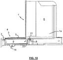
- the tray 6 has an orifice 21, visible to figures 9 and 10 .
- This orifice 21 is arranged so that in deployed configuration and in retracted configuration, the orifice 21 is located at the right of the basin 4, above one of the flow recesses 7 or 8 of the basin 4.
- tray 6 may have a bottom and the orifice 21 may be practiced in the bottom of the tray 6.
- the tray 6 is not in contact with the basin 4. This prevents the propagation of vibrations from the vibrating pump. In addition it allows to change the position of the basin 4 and remove it to empty it without having to extract the tray 6 packaging.
- the pelvis 4 is not articulated on the tray 6. It does not cooperate mechanically with the latter. Thus, a user can remove the basin from the machine while leaving in place the tray 6 for packaging. Typically, a distance of a few millimeters separates the basin 4 from the tray 6 to packaging.
- the basin 4 has at least one fulcrum
- the figures two complementary support points 13 configured to each bear on an inner portion of the body 1a of the machine 1. This is obtained because the Basin 4 has two arms 12 each carrying a complementary fulcrum 13 intended to bear on the body 1a of the machine 1, said arms 12 being intended to serve as sliding guide during the passage of the pelvis 4 of a position to the other.
- These two arms 12 extend from the rear of the receptacle 9 of the pelvis 4 and are able to cooperate with guide surfaces 16 respectively present on each side of the housing 11 carried by the body 1a of the machine 1.
- These surfaces of guide 16 are advantageously in the form of a parallelepipedic slide arranged on each of the two longitudinal inner sides of the housing 11.
- Each of the complementary bearing points 13 has an elastic portion ensuring the contact between the pelvis 4 and the guide surface 16 present inside the housing 11.
- Each of the complementary bearing points 13 is advantageously supported with the surface of guidance 16 by a spherical plane point-to-plane connection, as shown in FIG. figure 3 . This limits the friction surface when moving from the retracted position to the deployed position.
- the pelvis 4 has indexing means. These indexing means serve to place the pelvis 4 exactly in its extended or retracted position, in particular so that the pelvis 4 is in its exact position with respect to the tray 6 for collecting the used packaging arranged above it.
- the indexing means may be recessed means protruding into penetrating holes provided in portions of the housing 11 opposite, this as for the retracted position as the deployed position of the pelvis 4 when the means raised projection are exactly opposite holes.
- the machine 1 is configured so that its body 1a rests on a working plane, which plane is advantageously substantially horizontal.
- the pelvis 4 has at least one fulcrum 14 intended to rest on the working plane of the machine 1. This reduces the transmission of vibrations from the vibrating pump.
- the machine 1 is configured so that the basin 4 has at least one support point and preferably two support points 14 arranged to rest on the working plane of the machine 1.
- the two support points 14 are located symmetrically with respect to the longitudinal median plane of the pelvis 4, this advantageously in the front portion of the pelvis 4. This increases the stability of the assembly.
- Basin 4 is therefore supported on the working plane of the machine 1 by means of the two bearing points 14, preferably elastomeric feet, located in the front part on either side of its median vertical plane.
- the alignment of these two support points 14, preferably in the form of feet, defines a dummy line around which the volume of the pelvis 4 is likely to rock.
- Basin 4 then naturally finds a position of equilibrium by the support of its longitudinal arms 12 on the base of the slides 16 made in the body 1a of the machine 1.
- the basin 4 allows the passage to a container of greater height directly on the work surface.
- the two lower bearing points 14 situated at the front of the basin 4 always remain in contact with the work surface and retain the same articulation of the pelvis 4 relative to the body 1a of the machine 1 to also limit the transmission of vibrations in this retracted position.
- the pelvis 4 on its two longitudinal faces, comprises at least one notch 15, preferably two notches 15 per face. Through these notches 15, the user can insert his finger into one or other of the notches to slide the pelvis 4 towards one of its two positions is retracted or deployed that it can take relative to the body 1a of the machine 1.
- a complementary notch 15a may be provided on the body 1a of the infuser to allow the user a quick recognition that the pelvis 4 is in its exact retracted or output position, which is very advantageous, in addition to or without the indexing means, to ensure an exact position of the basin 4 below the tray 6 for collecting used packaging, so that the basin 4 receives well through its flow recesses 7 and 8 the liquid likely to flow from the tray 6.
- the Figures 5 to 8 show a complete brewing machine, that is to say with the tray 6 mounted on the body.
- the tray 6 is inserted in a reception area 18.
- the tray 6 for collecting used packaging extends substantially from the lower end of the extraction module 2 to the basin 4
- the space 18 is occupied by the tray 6 and, in the retracted position, it is only visible from the pelvis 4 that its front face.
- Tray 6 had been removed from figures 1 and 2 to better show the basin 4.
- it is the tray 6 which carries on each of its lateral sides the complementary notches 15a previously mentioned.
- a complete infuser machine is shown at figure 7 with as a beverage container a large container 20 of the type mug.
- the pelvis 4 is in retracted position and, because of the presence of the tray 6 and the decoration piece 19, only the front face 10 and the front part of the lateral face of the pelvis 4 are visible. In this position, it is the recess front flow 7 which is located under the ejection orifice 21 of the containers of the tray 6, recess 7 which is not visible in this figure because covered by the tray 6.
- a complete infuser machine is shown at figure 8 with as a beverage container a small container 20a cup type.
- the basin 4 is in the deployed position and in this position, it is the rear flow recess 8 which is located under the orifice 21 of the tank 6.
- the front flow recess 7 is visible but is not in use.
- control panel 17 provided with pictograms 17a and 17, preferably in the form of buttons, to select the quantity of beverage to be poured depending on the type of container to be used, either a large container 20 or a small container 20a and to actuate the pouring of the selected amount of beverage.
Landscapes
- Engineering & Computer Science (AREA)
- Food Science & Technology (AREA)
- Physics & Mathematics (AREA)
- Thermal Sciences (AREA)
- Devices For Dispensing Beverages (AREA)
- Apparatus For Making Beverages (AREA)
Claims (15)
- Gerät (1) zur Zubereitung eines Aufgussgetränks, bestehend aus einem Gehäuse (1a) und einem Modul (2) zur Extraktion eines in einer Abfüllung enthaltenen Aufgussprodukts, welche eine kleine Wanne (4) umfasst, wobei das Gerät so gestaltet ist, dass die kleine Wanne (4) in einer ausgefahrenen Position als Halterung für ein zur Aufnahme des Getränks bestimmten Behältnisses (20, 20a) dienen kann, und in einer eingefahrenen Position zumindest teilweise im Inneren des Gehäuses (1a) des Gerätes (1) gelagert ist, wobei das Gerät (1) so gestaltet ist, dass der Wechsel von der ausgefahrenen Position in die eingefahrene Position und umgekehrt durch eine Schubbewegung erfolgt, dadurch gekennzeichnet dass es so gestaltet ist, dass es auf einer Arbeitsfläche abgestellt werden kann und dadurch, dass die kleine Wanne (4) mindestens einen Auflagerpunkt (14) aufweist, der auf dieser Arbeitsfläche aufliegt.
- Gerät (1) nach dem vorhergehenden Anspruch, in welchem die kleine Wanne (4) in eingefahrener Position komplett im Gehäuse (1a) des Geräts (1) gelagert ist. In diesem Gerät weist vorzugsweise die kleine Wanne (4) eine senkrechte Frontfläche (10) und das Gehäuse (1a) des Geräts (1) eine senkrechte Fläche mit einer Aufnahme (11) für die kleine Wanne (4) auf, wobei diese Fläche so gestaltet ist, dass die Frontfläche (10) der kleinen Wanne (4) in der eingefahrenen Position vorzugsweise im rechten Winkel zur vertikalen Fläche des Geräts (1) mit der Aufnahme (11) steht.
- Gerät (1) nach einem der vorhergehenden Ansprüche, in welchem das Gerät (1) so gestaltet ist, dass die kleine Wanne (4) mindestens zwei Auflagerpunkte (14) aufweist, die so angeordnet sind, dass sie auf besagter Arbeitsfläche aufstehen, wobei die beiden Auflagerpunkte (14) symmetrisch zu einer Mittelebene der kleinen Wanne (4) angeordnet sind.
- Gerät (1) nach einem der vorhergehenden Ansprüche, bei dem die kleine Wanne (4) mindestens einen zusätzlichen Auflagerpunkt (13) aufweist, der so gestaltet ist, dass er am Gehäuse (1a) des Geräts (1) anliegt.
- Gerät (1) nach dem vorhergehenden Anspruch, in welchem die kleine Wanne (4) zwei zusätzliche Auflagerpunkte (13) aufweist, die so gestaltet sind, dass sie jeweils am Gehäuse (1a) des Geräts (1) anliegen.
- Gerät (1) nach dem vorhergehenden Anspruch, in welchem die kleine Wanne (4) mindestens zwei Arme (12) umfasst, von denen jeder einen zusätzlichen Auflagerpunkt (13) trägt, der so gestaltet ist, dass er am Gehäuse (1a) des Geräts (1) anliegt, und in welchem die Arme (12) dazu bestimmt sind, beim Positionswechsel der kleinen Wanne (4) in einer Schubbewegung geführt zu werden.
- Gerät (1) nach einem der beiden vorhergehenden Ansprüche, bei dem die beiden zusätzlichen Auflagerpunkte (13) mit den Führungsflächen (16) im Innern der Aufnahme (11) zusammenwirken, wobei die kleine Wanne (4) im Innern der Aufnahme mindestens teilweise eingefahren gelagert ist.
- Gerät (1) nach einem der beiden vorhergehenden Ansprüche, bei dem jeder der zusätzlichen Auflagerpunkte (13) einen elastischen Abschnitt aufweist, welcher den Kontakt zwischen der kleinen Wanne (4) und dem Gehäuse (1a) des Gerätes gewährleistet und in welchem jeder zusätzliche Auflagerpunkt (13) am Gehäuse (1a) vorzugsweise durch eine punktuelle Verbindung, wie zum Beispiel der Berührpunkt einer Kugel mit einer Ebene, am Gehäuse anliegt
- Gerät (1) nach einem der vorhergehenden Ansprüche, welches Indexierungsmittel aufweist, die so angeordnet sind, dass die kleine Wanne (4) in Bezug auf das Gehäuse (1a) des Geräts (1) in der ein- und ausgefahrenen Position indexiert werden kann.
- Gerät (1) nach einem der vorhergehenden Ansprüche, in welchem das Gerät (1) so gestaltet ist, dass Abfüllungen eines Aufgussprodukts aufgenommen werden können, um das in der Abfüllung enthaltene Produkt zu extrahieren, wobei das Gerät (1) einen Behälter (6) zur Aufnahme der aufgegossenen Abfüllungen enthält, wobei das Gerät (1) des Weiteren so gestaltet ist, dass der Behälter (6) mit der kleinen Wanne (4) in eingefahrener und ausgefahrener Position in Strömungsverbindung steht.
- Gerät (1) nach dem vorhergehenden Anspruch, in welchem der für die Abfüllungen bestimmte Behälter (6) mechanisch unabhängig von der kleinen Wanne (4).
- Gerät (1) nach einem der beiden vorhergehenden Ansprüche, in welchem der Behälter (6) eine Öffnung (21) aufweist, die so angeordnet ist, dass sie in eingefahrener und in ausgefahrener Position rechtwinklig zur kleinen Wanne (4) steht.
- Gerät (1) nach dem vorhergehenden Anspruch, in dem die kleine Wanne (4) zwei Ausflussaussparungen (7, 8) aufweist, die zu deren oberen Bereich führen und mit dem Innenbereich verbunden sind, wobei die beiden Ausflussaussparungen (7, 8) in der kleinen Wanne (4) so angeordnet sind, dass eine der beiden Ausflussaussparungen (7) in eingefahrener Position der kleinen Wanne (4) in Strömungsverbindung mit der Öffnung (21) des Behälters (6) steht und die andere (8) in ausgefahrener Position der kleinen Wanne (4) mit der Öffnung (21) des Behälters (6) in Strömungsverbindung steht.
- Gerät (1) nach einem der vorhergehenden Ansprüche, indem die kleine Wanne (4) einen hohlen Innenraum aufweist, der einen Flüssigkeitsbehälter (9) bildet, und in welchem der Flüssigkeitsbehälter (9) und die kleine Wanne (4) mit vorspringenden Teilen (5) bedeckt ist, die sich im Wesentlichen senkrecht erstrecken und von denen zumindest einige der oberen Enden auf ein und derselben Ebene liegen, um eine Auflagefläche für einen Behälter (20, 20a) zu bilden, der dazu bestimmt ist, auf die kleine Wanne (4) gestellt zu werden, wobei der Flüssigkeitsbehälter (9) und die vorspringenden Teile (5) ein einziges Stück bilden.
- Gerät (1) nach dem vorhergehenden Anspruch, in dem das einzige Stück durch Formung erzielt wird und die vorspringenden Teile (5) vorzugsweise vertikale Rippen bilden.
Applications Claiming Priority (2)
| Application Number | Priority Date | Filing Date | Title |
|---|---|---|---|
| FR1256021A FR2992155B1 (fr) | 2012-06-25 | 2012-06-25 | Machine de preparation de boisson par infusion comportant une bassinelle coulissante |
| PCT/EP2013/063320 WO2014001362A1 (fr) | 2012-06-25 | 2013-06-25 | Machine de préparation de boisson par infusion comportant une bassinelle coulissante |
Publications (2)
| Publication Number | Publication Date |
|---|---|
| EP2863777A1 EP2863777A1 (de) | 2015-04-29 |
| EP2863777B1 true EP2863777B1 (de) | 2018-06-06 |
Family
ID=47003001
Family Applications (1)
| Application Number | Title | Priority Date | Filing Date |
|---|---|---|---|
| EP13730915.9A Active EP2863777B1 (de) | 2012-06-25 | 2013-06-25 | Maschine mit verschiebbarer tropfenschale zur zubereitung von getränken mittels infusion |
Country Status (3)
| Country | Link |
|---|---|
| EP (1) | EP2863777B1 (de) |
| FR (1) | FR2992155B1 (de) |
| WO (1) | WO2014001362A1 (de) |
Cited By (7)
| Publication number | Priority date | Publication date | Assignee | Title |
|---|---|---|---|---|
| US12279629B1 (en) | 2024-01-18 | 2025-04-22 | Sharkninja Operating Llc | Mixing vessel baffles for a drink maker |
| USD1076580S1 (en) | 2024-01-18 | 2025-05-27 | Sharkninja Operating Llc | Drink maker dasher |
| USD1091236S1 (en) | 2024-01-18 | 2025-09-02 | Sharkninja Operating Llc | Collection tray for a drink maker |
| US12414578B1 (en) | 2025-03-14 | 2025-09-16 | Sharkninja Operating Llc | Shared output connector assembly for two drink maker dispenser assemblies |
| US12446594B2 (en) | 2024-01-18 | 2025-10-21 | Sharkninja Operating Llc | Drink maker with detachably connectable mixing vessel |
| US12514262B1 (en) | 2025-01-10 | 2026-01-06 | Sharkninja Operating Llc | Feature for preventing material buildup in a mixing vessel of a drink maker |
| US12520857B1 (en) | 2025-01-09 | 2026-01-13 | Sharkninja Operating Llc | Multi-stage dispenser assembly |
Families Citing this family (6)
| Publication number | Priority date | Publication date | Assignee | Title |
|---|---|---|---|---|
| WO2015110128A1 (en) * | 2014-01-22 | 2015-07-30 | Aktiebolaget Electrolux | Drip plate assembly and beverage dispenser comprising a drip plate assembly |
| DE102015203740A1 (de) * | 2015-03-03 | 2016-09-08 | BSH Hausgeräte GmbH | Kaffeeautomat |
| EP3277138B1 (de) * | 2015-04-02 | 2021-01-06 | Société des Produits Nestlé S.A. | Arretierender becherträger |
| EP3158900A1 (de) * | 2015-10-20 | 2017-04-26 | Qbo Coffee GmbH | Getränkezubereitungsmaschine |
| CN107550298A (zh) * | 2017-10-12 | 2018-01-09 | 汕头市智润科技发展有限公司 | 饮水机的接水装置 |
| IT201900001175A1 (it) * | 2019-01-25 | 2020-07-25 | De Longhi Appliances Srl | Macchina da caffè con vaschetta per la raccolta di liquidi migliorata |
Family Cites Families (4)
| Publication number | Priority date | Publication date | Assignee | Title |
|---|---|---|---|---|
| FR2709655B1 (fr) | 1993-09-06 | 1995-11-24 | Cafes Cie Mediterraneenne | Machine à café express utilisant un conditionnement de café moulu du type pastille pré-dosée. |
| DE202004020983U1 (de) * | 2004-08-04 | 2006-06-14 | BSH Bosch und Siemens Hausgeräte GmbH | Getränkebereiter und Auslaufeinrichtung für einen Getränkebereiter |
| DE602005007475D1 (de) * | 2005-06-07 | 2008-07-24 | Nestec Sa | Getränkemaschine mit Auffangwanne für Behälter unterschiedlicher Höhe |
| DE202010000024U1 (de) * | 2010-01-12 | 2011-05-19 | Wik Far East Ltd. | Getränkezubereitungsmaschine |
-
2012
- 2012-06-25 FR FR1256021A patent/FR2992155B1/fr not_active Expired - Fee Related
-
2013
- 2013-06-25 WO PCT/EP2013/063320 patent/WO2014001362A1/fr not_active Ceased
- 2013-06-25 EP EP13730915.9A patent/EP2863777B1/de active Active
Non-Patent Citations (1)
| Title |
|---|
| None * |
Cited By (9)
| Publication number | Priority date | Publication date | Assignee | Title |
|---|---|---|---|---|
| US12279629B1 (en) | 2024-01-18 | 2025-04-22 | Sharkninja Operating Llc | Mixing vessel baffles for a drink maker |
| US12285028B1 (en) | 2024-01-18 | 2025-04-29 | Sharkninja Operating Llc | Mixing vessel baffles for a drink maker |
| USD1076580S1 (en) | 2024-01-18 | 2025-05-27 | Sharkninja Operating Llc | Drink maker dasher |
| USD1091236S1 (en) | 2024-01-18 | 2025-09-02 | Sharkninja Operating Llc | Collection tray for a drink maker |
| US12446594B2 (en) | 2024-01-18 | 2025-10-21 | Sharkninja Operating Llc | Drink maker with detachably connectable mixing vessel |
| US12593855B2 (en) | 2024-01-18 | 2026-04-07 | Sharkninja Operating Llc | Drink maker with detachably connectable mixing vessel |
| US12520857B1 (en) | 2025-01-09 | 2026-01-13 | Sharkninja Operating Llc | Multi-stage dispenser assembly |
| US12514262B1 (en) | 2025-01-10 | 2026-01-06 | Sharkninja Operating Llc | Feature for preventing material buildup in a mixing vessel of a drink maker |
| US12414578B1 (en) | 2025-03-14 | 2025-09-16 | Sharkninja Operating Llc | Shared output connector assembly for two drink maker dispenser assemblies |
Also Published As
| Publication number | Publication date |
|---|---|
| WO2014001362A1 (fr) | 2014-01-03 |
| FR2992155B1 (fr) | 2015-02-20 |
| FR2992155A1 (fr) | 2013-12-27 |
| EP2863777A1 (de) | 2015-04-29 |
Similar Documents
| Publication | Publication Date | Title |
|---|---|---|
| EP2863777B1 (de) | Maschine mit verschiebbarer tropfenschale zur zubereitung von getränken mittels infusion | |
| EP1208782B1 (de) | Perkolationsvorrichtung | |
| RU2488334C2 (ru) | Подставка с двойной опорной поверхностью для чашек и других емкостей в машинах для приготовления напитков | |
| EP2189088B1 (de) | Getränkeautomat mit Auflagesystem und Tropffänger für Behälter verschiedener Größen | |
| EP3398486B1 (de) | Getränkezubereitungsmaschine, u. a. von milchgetränken, die mit einer brause und einem padhalter ausgestattet ist | |
| EP2281494B1 (de) | Metering spoon | |
| EP3682773A1 (de) | Getränkezubereitungsmaschine, die mit einem verbesserten auffangbehälter für benutzte kapseln ausgestattet ist | |
| FR2953112A1 (fr) | Appareil de preparation de boissons infusees avec reserve amovible | |
| EP2704615B1 (de) | Ausgiesszubehör für einen getränkeautomat | |
| MX2008001943A (es) | Dispositivos para la preparacion de bebidas que comprenden tubos moviles. | |
| EP3708038B1 (de) | Maschine zur herstellung von aufgussgetränken, die mit einem drehbaren filterkorb ausgestattet ist | |
| EP3398489B1 (de) | Getränkezubereitungsmaschine, die mit einer versenkbaren halterung für behälter ausgestattet ist | |
| WO2006120314A1 (fr) | Machine a cafe comportant un dispositif de confection de mousse | |
| EP3970579B1 (de) | Automatische kaffeemaschine mit kippschutzvorrichtung einer kuchenschale | |
| EP3937738B1 (de) | Maschine zur herstellung von brühgetränken mit aufhebbarem filterkorb | |
| EP2854606B1 (de) | Infusionskasten für einen getränkeautomaten | |
| EP4678074A1 (de) | Getränkeherstellungsvorrichtung mit verbessertem behälterhalter | |
| FR2955239A3 (fr) | Recipient multiple reversible | |
| EP4437914A1 (de) | Kaffeetrestersammelbehälter und kaffeemaschine mit einem solchen behälter | |
| EP2745752B1 (de) | Deckel eines Ausgussgefäßes, und Einheit für die Getränkeausgabe, die einen solchen Deckel und ein solches Ausgussgefäß umfasst | |
| CA2618186A1 (en) | Squeezed coffee | |
| EP4598407A1 (de) | Getränkeausgabemaschine mit vertikal verschiebbarer milchaufschäumvorrichtung | |
| FR3093631A1 (fr) | Machine de preparation de boissons infusees munie d’un filtre ameliore | |
| FR2824247A1 (fr) | Machine a boissons chaudes comportant un receptacle pivotant perfore pour matieres aromatiques | |
| BE470241A (de) |
Legal Events
| Date | Code | Title | Description |
|---|---|---|---|
| PUAI | Public reference made under article 153(3) epc to a published international application that has entered the european phase |
Free format text: ORIGINAL CODE: 0009012 |
|
| 17P | Request for examination filed |
Effective date: 20150115 |
|
| AK | Designated contracting states |
Kind code of ref document: A1 Designated state(s): AL AT BE BG CH CY CZ DE DK EE ES FI FR GB GR HR HU IE IS IT LI LT LU LV MC MK MT NL NO PL PT RO RS SE SI SK SM TR |
|
| AX | Request for extension of the european patent |
Extension state: BA ME |
|
| DAX | Request for extension of the european patent (deleted) | ||
| GRAP | Despatch of communication of intention to grant a patent |
Free format text: ORIGINAL CODE: EPIDOSNIGR1 |
|
| STAA | Information on the status of an ep patent application or granted ep patent |
Free format text: STATUS: GRANT OF PATENT IS INTENDED |
|
| INTG | Intention to grant announced |
Effective date: 20171220 |
|
| GRAS | Grant fee paid |
Free format text: ORIGINAL CODE: EPIDOSNIGR3 |
|
| GRAA | (expected) grant |
Free format text: ORIGINAL CODE: 0009210 |
|
| STAA | Information on the status of an ep patent application or granted ep patent |
Free format text: STATUS: THE PATENT HAS BEEN GRANTED |
|
| AK | Designated contracting states |
Kind code of ref document: B1 Designated state(s): AL AT BE BG CH CY CZ DE DK EE ES FI FR GB GR HR HU IE IS IT LI LT LU LV MC MK MT NL NO PL PT RO RS SE SI SK SM TR |
|
| REG | Reference to a national code |
Ref country code: GB Ref legal event code: FG4D Free format text: NOT ENGLISH |
|
| REG | Reference to a national code |
Ref country code: CH Ref legal event code: EP Ref country code: AT Ref legal event code: REF Ref document number: 1005118 Country of ref document: AT Kind code of ref document: T Effective date: 20180615 |
|
| REG | Reference to a national code |
Ref country code: IE Ref legal event code: FG4D Free format text: LANGUAGE OF EP DOCUMENT: FRENCH |
|
| REG | Reference to a national code |
Ref country code: FR Ref legal event code: PLFP Year of fee payment: 6 |
|
| REG | Reference to a national code |
Ref country code: DE Ref legal event code: R096 Ref document number: 602013038556 Country of ref document: DE |
|
| REG | Reference to a national code |
Ref country code: NL Ref legal event code: MP Effective date: 20180606 |
|
| REG | Reference to a national code |
Ref country code: LT Ref legal event code: MG4D |
|
| PG25 | Lapsed in a contracting state [announced via postgrant information from national office to epo] |
Ref country code: ES Free format text: LAPSE BECAUSE OF FAILURE TO SUBMIT A TRANSLATION OF THE DESCRIPTION OR TO PAY THE FEE WITHIN THE PRESCRIBED TIME-LIMIT Effective date: 20180606 Ref country code: SE Free format text: LAPSE BECAUSE OF FAILURE TO SUBMIT A TRANSLATION OF THE DESCRIPTION OR TO PAY THE FEE WITHIN THE PRESCRIBED TIME-LIMIT Effective date: 20180606 Ref country code: NO Free format text: LAPSE BECAUSE OF FAILURE TO SUBMIT A TRANSLATION OF THE DESCRIPTION OR TO PAY THE FEE WITHIN THE PRESCRIBED TIME-LIMIT Effective date: 20180906 Ref country code: FI Free format text: LAPSE BECAUSE OF FAILURE TO SUBMIT A TRANSLATION OF THE DESCRIPTION OR TO PAY THE FEE WITHIN THE PRESCRIBED TIME-LIMIT Effective date: 20180606 Ref country code: BG Free format text: LAPSE BECAUSE OF FAILURE TO SUBMIT A TRANSLATION OF THE DESCRIPTION OR TO PAY THE FEE WITHIN THE PRESCRIBED TIME-LIMIT Effective date: 20180906 Ref country code: LT Free format text: LAPSE BECAUSE OF FAILURE TO SUBMIT A TRANSLATION OF THE DESCRIPTION OR TO PAY THE FEE WITHIN THE PRESCRIBED TIME-LIMIT Effective date: 20180606 Ref country code: CY Free format text: LAPSE BECAUSE OF FAILURE TO SUBMIT A TRANSLATION OF THE DESCRIPTION OR TO PAY THE FEE WITHIN THE PRESCRIBED TIME-LIMIT Effective date: 20180606 |
|
| PG25 | Lapsed in a contracting state [announced via postgrant information from national office to epo] |
Ref country code: GR Free format text: LAPSE BECAUSE OF FAILURE TO SUBMIT A TRANSLATION OF THE DESCRIPTION OR TO PAY THE FEE WITHIN THE PRESCRIBED TIME-LIMIT Effective date: 20180907 Ref country code: HR Free format text: LAPSE BECAUSE OF FAILURE TO SUBMIT A TRANSLATION OF THE DESCRIPTION OR TO PAY THE FEE WITHIN THE PRESCRIBED TIME-LIMIT Effective date: 20180606 Ref country code: RS Free format text: LAPSE BECAUSE OF FAILURE TO SUBMIT A TRANSLATION OF THE DESCRIPTION OR TO PAY THE FEE WITHIN THE PRESCRIBED TIME-LIMIT Effective date: 20180606 Ref country code: LV Free format text: LAPSE BECAUSE OF FAILURE TO SUBMIT A TRANSLATION OF THE DESCRIPTION OR TO PAY THE FEE WITHIN THE PRESCRIBED TIME-LIMIT Effective date: 20180606 |
|
| REG | Reference to a national code |
Ref country code: AT Ref legal event code: MK05 Ref document number: 1005118 Country of ref document: AT Kind code of ref document: T Effective date: 20180606 |
|
| PG25 | Lapsed in a contracting state [announced via postgrant information from national office to epo] |
Ref country code: NL Free format text: LAPSE BECAUSE OF FAILURE TO SUBMIT A TRANSLATION OF THE DESCRIPTION OR TO PAY THE FEE WITHIN THE PRESCRIBED TIME-LIMIT Effective date: 20180606 |
|
| REG | Reference to a national code |
Ref country code: DE Ref legal event code: R119 Ref document number: 602013038556 Country of ref document: DE |
|
| PG25 | Lapsed in a contracting state [announced via postgrant information from national office to epo] |
Ref country code: RO Free format text: LAPSE BECAUSE OF FAILURE TO SUBMIT A TRANSLATION OF THE DESCRIPTION OR TO PAY THE FEE WITHIN THE PRESCRIBED TIME-LIMIT Effective date: 20180606 Ref country code: CZ Free format text: LAPSE BECAUSE OF FAILURE TO SUBMIT A TRANSLATION OF THE DESCRIPTION OR TO PAY THE FEE WITHIN THE PRESCRIBED TIME-LIMIT Effective date: 20180606 Ref country code: EE Free format text: LAPSE BECAUSE OF FAILURE TO SUBMIT A TRANSLATION OF THE DESCRIPTION OR TO PAY THE FEE WITHIN THE PRESCRIBED TIME-LIMIT Effective date: 20180606 Ref country code: AT Free format text: LAPSE BECAUSE OF FAILURE TO SUBMIT A TRANSLATION OF THE DESCRIPTION OR TO PAY THE FEE WITHIN THE PRESCRIBED TIME-LIMIT Effective date: 20180606 Ref country code: IS Free format text: LAPSE BECAUSE OF FAILURE TO SUBMIT A TRANSLATION OF THE DESCRIPTION OR TO PAY THE FEE WITHIN THE PRESCRIBED TIME-LIMIT Effective date: 20181006 Ref country code: SK Free format text: LAPSE BECAUSE OF FAILURE TO SUBMIT A TRANSLATION OF THE DESCRIPTION OR TO PAY THE FEE WITHIN THE PRESCRIBED TIME-LIMIT Effective date: 20180606 Ref country code: PL Free format text: LAPSE BECAUSE OF FAILURE TO SUBMIT A TRANSLATION OF THE DESCRIPTION OR TO PAY THE FEE WITHIN THE PRESCRIBED TIME-LIMIT Effective date: 20180606 |
|
| REG | Reference to a national code |
Ref country code: CH Ref legal event code: PL |
|
| PG25 | Lapsed in a contracting state [announced via postgrant information from national office to epo] |
Ref country code: IT Free format text: LAPSE BECAUSE OF FAILURE TO SUBMIT A TRANSLATION OF THE DESCRIPTION OR TO PAY THE FEE WITHIN THE PRESCRIBED TIME-LIMIT Effective date: 20180606 Ref country code: SM Free format text: LAPSE BECAUSE OF FAILURE TO SUBMIT A TRANSLATION OF THE DESCRIPTION OR TO PAY THE FEE WITHIN THE PRESCRIBED TIME-LIMIT Effective date: 20180606 |
|
| REG | Reference to a national code |
Ref country code: IE Ref legal event code: MM4A |
|
| PG25 | Lapsed in a contracting state [announced via postgrant information from national office to epo] |
Ref country code: MC Free format text: LAPSE BECAUSE OF FAILURE TO SUBMIT A TRANSLATION OF THE DESCRIPTION OR TO PAY THE FEE WITHIN THE PRESCRIBED TIME-LIMIT Effective date: 20180606 Ref country code: LU Free format text: LAPSE BECAUSE OF NON-PAYMENT OF DUE FEES Effective date: 20180625 |
|
| PLBE | No opposition filed within time limit |
Free format text: ORIGINAL CODE: 0009261 |
|
| STAA | Information on the status of an ep patent application or granted ep patent |
Free format text: STATUS: NO OPPOSITION FILED WITHIN TIME LIMIT |
|
| PG25 | Lapsed in a contracting state [announced via postgrant information from national office to epo] |
Ref country code: CH Free format text: LAPSE BECAUSE OF NON-PAYMENT OF DUE FEES Effective date: 20180630 Ref country code: LI Free format text: LAPSE BECAUSE OF NON-PAYMENT OF DUE FEES Effective date: 20180630 Ref country code: DE Free format text: LAPSE BECAUSE OF NON-PAYMENT OF DUE FEES Effective date: 20190101 Ref country code: IE Free format text: LAPSE BECAUSE OF NON-PAYMENT OF DUE FEES Effective date: 20180625 |
|
| 26N | No opposition filed |
Effective date: 20190307 |
|
| GBPC | Gb: european patent ceased through non-payment of renewal fee |
Effective date: 20180906 |
|
| PG25 | Lapsed in a contracting state [announced via postgrant information from national office to epo] |
Ref country code: DK Free format text: LAPSE BECAUSE OF FAILURE TO SUBMIT A TRANSLATION OF THE DESCRIPTION OR TO PAY THE FEE WITHIN THE PRESCRIBED TIME-LIMIT Effective date: 20180606 Ref country code: SI Free format text: LAPSE BECAUSE OF FAILURE TO SUBMIT A TRANSLATION OF THE DESCRIPTION OR TO PAY THE FEE WITHIN THE PRESCRIBED TIME-LIMIT Effective date: 20180606 |
|
| PG25 | Lapsed in a contracting state [announced via postgrant information from national office to epo] |
Ref country code: GB Free format text: LAPSE BECAUSE OF NON-PAYMENT OF DUE FEES Effective date: 20180906 |
|
| PG25 | Lapsed in a contracting state [announced via postgrant information from national office to epo] |
Ref country code: AL Free format text: LAPSE BECAUSE OF FAILURE TO SUBMIT A TRANSLATION OF THE DESCRIPTION OR TO PAY THE FEE WITHIN THE PRESCRIBED TIME-LIMIT Effective date: 20180606 |
|
| PG25 | Lapsed in a contracting state [announced via postgrant information from national office to epo] |
Ref country code: MT Free format text: LAPSE BECAUSE OF FAILURE TO SUBMIT A TRANSLATION OF THE DESCRIPTION OR TO PAY THE FEE WITHIN THE PRESCRIBED TIME-LIMIT Effective date: 20180606 |
|
| PG25 | Lapsed in a contracting state [announced via postgrant information from national office to epo] |
Ref country code: TR Free format text: LAPSE BECAUSE OF FAILURE TO SUBMIT A TRANSLATION OF THE DESCRIPTION OR TO PAY THE FEE WITHIN THE PRESCRIBED TIME-LIMIT Effective date: 20180606 |
|
| PG25 | Lapsed in a contracting state [announced via postgrant information from national office to epo] |
Ref country code: PT Free format text: LAPSE BECAUSE OF FAILURE TO SUBMIT A TRANSLATION OF THE DESCRIPTION OR TO PAY THE FEE WITHIN THE PRESCRIBED TIME-LIMIT Effective date: 20180606 |
|
| PG25 | Lapsed in a contracting state [announced via postgrant information from national office to epo] |
Ref country code: HU Free format text: LAPSE BECAUSE OF FAILURE TO SUBMIT A TRANSLATION OF THE DESCRIPTION OR TO PAY THE FEE WITHIN THE PRESCRIBED TIME-LIMIT; INVALID AB INITIO Effective date: 20130625 Ref country code: MK Free format text: LAPSE BECAUSE OF NON-PAYMENT OF DUE FEES Effective date: 20180606 |
|
| P01 | Opt-out of the competence of the unified patent court (upc) registered |
Effective date: 20230601 |
|
| PGFP | Annual fee paid to national office [announced via postgrant information from national office to epo] |
Ref country code: BE Payment date: 20250625 Year of fee payment: 13 |
|
| PGFP | Annual fee paid to national office [announced via postgrant information from national office to epo] |
Ref country code: FR Payment date: 20250625 Year of fee payment: 13 |