EP2864112B1 - Procédé permettant de coller un calandrage intérieur à une nappe de carcasse d'un pneu - Google Patents
Procédé permettant de coller un calandrage intérieur à une nappe de carcasse d'un pneu Download PDFInfo
- Publication number
- EP2864112B1 EP2864112B1 EP12879193.6A EP12879193A EP2864112B1 EP 2864112 B1 EP2864112 B1 EP 2864112B1 EP 12879193 A EP12879193 A EP 12879193A EP 2864112 B1 EP2864112 B1 EP 2864112B1
- Authority
- EP
- European Patent Office
- Prior art keywords
- reinforcing ply
- drum
- pair
- tire components
- air impermeable
- Prior art date
- Legal status (The legal status is an assumption and is not a legal conclusion. Google has not performed a legal analysis and makes no representation as to the accuracy of the status listed.)
- Active
Links
Images


Classifications
-
- B—PERFORMING OPERATIONS; TRANSPORTING
- B29—WORKING OF PLASTICS; WORKING OF SUBSTANCES IN A PLASTIC STATE IN GENERAL
- B29D—PRODUCING PARTICULAR ARTICLES FROM PLASTICS OR FROM SUBSTANCES IN A PLASTIC STATE
- B29D30/00—Producing pneumatic or solid tyres or parts thereof
- B29D30/06—Pneumatic tyres or parts thereof (e.g. produced by casting, moulding, compression moulding, injection moulding, centrifugal casting)
- B29D30/36—Expansion of tyres in a flat form, i.e. expansion to a toroidal shape independently of their building-up process, e.g. of tyres built by the flat-tyres method or by jointly covering two bead-rings
-
- B—PERFORMING OPERATIONS; TRANSPORTING
- B29—WORKING OF PLASTICS; WORKING OF SUBSTANCES IN A PLASTIC STATE IN GENERAL
- B29D—PRODUCING PARTICULAR ARTICLES FROM PLASTICS OR FROM SUBSTANCES IN A PLASTIC STATE
- B29D30/00—Producing pneumatic or solid tyres or parts thereof
-
- B—PERFORMING OPERATIONS; TRANSPORTING
- B29—WORKING OF PLASTICS; WORKING OF SUBSTANCES IN A PLASTIC STATE IN GENERAL
- B29D—PRODUCING PARTICULAR ARTICLES FROM PLASTICS OR FROM SUBSTANCES IN A PLASTIC STATE
- B29D30/00—Producing pneumatic or solid tyres or parts thereof
- B29D30/06—Pneumatic tyres or parts thereof (e.g. produced by casting, moulding, compression moulding, injection moulding, centrifugal casting)
- B29D30/08—Building tyres
- B29D30/10—Building tyres on round cores, i.e. the shape of the core is approximately identical with the shape of the completed tyre
- B29D30/16—Applying the layers; Guiding or stretching the layers during application
-
- B—PERFORMING OPERATIONS; TRANSPORTING
- B29—WORKING OF PLASTICS; WORKING OF SUBSTANCES IN A PLASTIC STATE IN GENERAL
- B29D—PRODUCING PARTICULAR ARTICLES FROM PLASTICS OR FROM SUBSTANCES IN A PLASTIC STATE
- B29D30/00—Producing pneumatic or solid tyres or parts thereof
- B29D30/06—Pneumatic tyres or parts thereof (e.g. produced by casting, moulding, compression moulding, injection moulding, centrifugal casting)
- B29D30/08—Building tyres
- B29D30/10—Building tyres on round cores, i.e. the shape of the core is approximately identical with the shape of the completed tyre
- B29D30/18—Fitting the bead-rings or bead-cores; Folding the textile layers around the rings or cores
-
- B—PERFORMING OPERATIONS; TRANSPORTING
- B29—WORKING OF PLASTICS; WORKING OF SUBSTANCES IN A PLASTIC STATE IN GENERAL
- B29D—PRODUCING PARTICULAR ARTICLES FROM PLASTICS OR FROM SUBSTANCES IN A PLASTIC STATE
- B29D30/00—Producing pneumatic or solid tyres or parts thereof
- B29D30/06—Pneumatic tyres or parts thereof (e.g. produced by casting, moulding, compression moulding, injection moulding, centrifugal casting)
- B29D30/08—Building tyres
- B29D30/20—Building tyres by the flat-tyre method, i.e. building on cylindrical drums
- B29D30/28—Rolling-down or pressing-down the layers in the building process
-
- B—PERFORMING OPERATIONS; TRANSPORTING
- B29—WORKING OF PLASTICS; WORKING OF SUBSTANCES IN A PLASTIC STATE IN GENERAL
- B29D—PRODUCING PARTICULAR ARTICLES FROM PLASTICS OR FROM SUBSTANCES IN A PLASTIC STATE
- B29D30/00—Producing pneumatic or solid tyres or parts thereof
- B29D30/06—Pneumatic tyres or parts thereof (e.g. produced by casting, moulding, compression moulding, injection moulding, centrifugal casting)
- B29D30/08—Building tyres
- B29D30/20—Building tyres by the flat-tyre method, i.e. building on cylindrical drums
- B29D30/32—Fitting the bead-rings or bead-cores; Folding the textile layers around the rings or cores
-
- B—PERFORMING OPERATIONS; TRANSPORTING
- B29—WORKING OF PLASTICS; WORKING OF SUBSTANCES IN A PLASTIC STATE IN GENERAL
- B29D—PRODUCING PARTICULAR ARTICLES FROM PLASTICS OR FROM SUBSTANCES IN A PLASTIC STATE
- B29D30/00—Producing pneumatic or solid tyres or parts thereof
- B29D30/06—Pneumatic tyres or parts thereof (e.g. produced by casting, moulding, compression moulding, injection moulding, centrifugal casting)
- B29D30/0681—Parts of pneumatic tyres; accessories, auxiliary operations
- B29D2030/0682—Inner liners
-
- B—PERFORMING OPERATIONS; TRANSPORTING
- B29—WORKING OF PLASTICS; WORKING OF SUBSTANCES IN A PLASTIC STATE IN GENERAL
- B29D—PRODUCING PARTICULAR ARTICLES FROM PLASTICS OR FROM SUBSTANCES IN A PLASTIC STATE
- B29D30/00—Producing pneumatic or solid tyres or parts thereof
- B29D30/06—Pneumatic tyres or parts thereof (e.g. produced by casting, moulding, compression moulding, injection moulding, centrifugal casting)
- B29D30/08—Building tyres
- B29D30/20—Building tyres by the flat-tyre method, i.e. building on cylindrical drums
- B29D2030/201—Manufacturing run-flat tyres
-
- B—PERFORMING OPERATIONS; TRANSPORTING
- B29—WORKING OF PLASTICS; WORKING OF SUBSTANCES IN A PLASTIC STATE IN GENERAL
- B29D—PRODUCING PARTICULAR ARTICLES FROM PLASTICS OR FROM SUBSTANCES IN A PLASTIC STATE
- B29D30/00—Producing pneumatic or solid tyres or parts thereof
- B29D30/06—Pneumatic tyres or parts thereof (e.g. produced by casting, moulding, compression moulding, injection moulding, centrifugal casting)
- B29D30/08—Building tyres
- B29D30/20—Building tyres by the flat-tyre method, i.e. building on cylindrical drums
- B29D30/30—Applying the layers; Guiding or stretching the layers during application
- B29D2030/3064—Details, accessories and auxiliary operations not otherwise provided for
- B29D2030/3071—Venting air inclusions during the layer applications, e.g. by creating grooves, channels, passages or holes in the band-like tyre component to be applied
Definitions
- the subject matter of the present disclosure relates generally to method of adhering the inner liner of a tire to a reinforcing ply.
- Tires are commonly manufactured using of one or more building drums upon which the tire is constructed from multiple layers and components that are placed sequentially onto the drum. For example, in one technique, a layer of air impermeable rubber is laid onto the forming surface of a cylindrical drum. One or more carcass plies are placed onto the drum. A pair of circular beads are placed on opposing sides and may include bead wires and bead fillers. The plies are turned up and the beads are moved towards each other to create a toroidal shape. A sidewall protective rubber and a tread portion are added.
- the addition of rubber elements into the sidewalls of the tire can be desirable for certain tire applications.
- the addition of rubber reinforcements into the sidewalls can be used along with other features to provide a tire that is capable of operating for a limited distance after losing inflation pressure. Such may allow the driver to reach a service center or other location more suitable than where the pressure loss occurred.
- the forming drum is typically a cylindrical shape having a flat profile along the axial direction but may have recesses for accepting features such as circular beads.
- the reinforcements create a profile that is no longer flat along the axial direction of the drum. Presentation of a carcass ply onto this uneven profile can result in undesirable creases or wrinkles - particularly when attempting to press the carcass ply towards the forming drum to make contact with e.g., an air impermeable layer on the forming drum.
- U.S. Patent No. 7,241,353 relates to method of manufacturing a tire having a crescent-shaped section using a building drum.
- U.S. 2005/002890 relates to a high crown, first stage tire building drum and a method of building a tire carcass.
- JP 2005 119227 relates to a tire molding method directed at preventing the occurrence of air pockets to enhance uniformity.
- a method for assembling a tire having one or more reinforcements or supports in the sidewalls would be useful. More particularly, such a method that can be used to reduce or avoid creases or wrinkles that can lead to deradialization and/or non-uniformities in the joining of the ends of the plies would be beneficial.
- the present invention provides a method of assembling a tire having one or more reinforcements or supporting inserts in the sidewalls.
- the reinforcements are positioned onto one or more air impermeable layers,
- One or more reinforcing plies are positioned over the reinforcing supports and suspended therebetween.
- a gas pressure is used to expand the one or more air impermeable layers away from the forming drum and against a reinforcing ply.
- the present invention provides a method of assembling tire components on a tire building drum having a cylindrically-shaped forming surface extending between opposing sides of the drum.
- the drum defines axial and circumferential directions.
- the method comprises the steps of laying one or more air impermeable layers onto the forming surface; positioning a pair of sidewall support inserts onto the one or more air impermeable layers with each sidewall support insert spaced from a respective side of the drum; placing at least one reinforcing ply over the pair of sidewall support inserts on the drum so as to suspend over the forming surface the at least on reinforcing ply between the pair of sidewall support inserts, wherein the at least one reinforcing ply comprises a plurality of perforations centrally positioned on the at least one reinforcing ply and spaced apart along a circumferential direction of the drum; stitching the at least one reinforcing ply to the pair of sidewall support inserts and to the one or more air impermeable
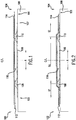
- Drum 100 has a cylindrically-shaped forming surface 101 that extends between opposing sides 102 and 104 and is substantially flat along the axial direction A and curved along circumferential direction C ( FIG. 8 ).
- Drum 100 is rotatable so as to allow various components to be presented onto the forming surface 101 in the construction of a tire.
- Drum 100 may include various internal features for positioning components placed onto surface 101.
- an air impermeable layer 106 (also referred to as an "inner liner") is placed onto forming surface 101 in a generally centered position between sides 102 and 104 as shown. While only one layer is illustrated, it should be understood that one or more air impermeable layers may be used.
- a pair of sidewall support inserts 108 and 110 are positioned onto the air impermeable layer 106. Each insert is placed at a predetermined distance from the sides 102 and 104 of drum 100 in an opposing manner and are generally equally spaced about center line C/L. The shape and size of the inserts is provided by way of example only and other configurations may be used. Additionally, while only a pair of inserts 108 are shown, more than one pair may be used to e.g., increase the sidewall strength of the assembled tire.
- a first reinforcing ply 112 and a second reinforcing ply 114 are placed onto the sidewall support inserts 108 and 110. While two plies 112 and 114 are shown in the figures, using the teachings disclosed herein it will be understood that a single reinforcing ply or more than two reinforcing plies may also be used. Additionally, where multiple reinforcing plies are used, such plies do not have to be applied over drum 100 at the same time.
- Plies 112 and 114 contain multiple cords and/or other reinforcing features that constrain the assembled tire while making plies 112 and 114 generally stiff and substantially non-expandable. As such, attempts to press plies 112 and 114 into contact with air impermeable layer 106 between inserts 108 and 110 can create creases as previously discussed. Accordingly, for this exemplary method of the present invention, plies 112 and 114 are placed onto sidewall support inserts 108 and 110 and are suspended over the forming surface 101 between the inserts 108 and 110. This creates a temporary cavity 116 extending circumferentially about drum 100 between air impermeable layer 106 and reinforcing ply 112.
- Each reinforcing ply includes a plurality of perforations along the circumferential direction. More particularly, as shown in FIG. 8 , reinforcing ply 112 includes a plurality of perforations 126 (e.g., holes or openings) that are spaced apart along circumferential direction C.
- each perforation 126 has a diameter in the range of about 2 mm to about 4 mm. In another exemplary embodiment, each perforation 126 has a diameter of about 3 mm or, for example, 3 mm ⁇ 0.5 mm.
- each perforation 126 is centrally positioned on reinforcing ply 112.
- perforations 126 should be located in the crown region of the tire.
- perforations 126 are within a range of about 0 to about 10 mm from centerline C/L.
- perforations 126 are positioned on or within ⁇ 0.5 mm of centerline C/L.
- Other placements may be used, provided perforations 126 are located in the crown region of the tire.
- Similar perforations are provided in reinforcing ply 114.
- a variety of techniques may be used to create perforations 126 in plies 112 and 114 as will be understood by one of skill in the art. The perforations can be created before plies 112 and 114 are applied or created as plies 112 and 114 are pulled onto drum 100.
- reinforcing plies 112 and 114 It is not necessary for the perforations in the reinforcing plies 112 and 114 to be aligned with each other. Also, while two plies 112 and 114 are shown, other constructions may also be used including a single reinforcing ply or more than two plies 112 and 114. In still another alternative, other components may be added between the application of reinforcing ply 112 and reinforcing ply 114. For example, reinforcing ply 112 may be positioned onto inserts 108 and 110.
- Additional sidewall reinforcement inserts may then be positioned into reinforcing ply 112 at positions axially outward of inserts 108 and 110 followed by the positioning of reinforcing ply 114 over or onto the same.
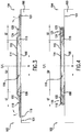
- reinforcing plies 112 and 114 are stitched against inserts 108 and 110 as well as air impermeable layer 106 as shown. More specifically, plies 112 and 114 are pressed towards the forming surface 101 at zones ST - which include inserts 108 and 110 and locations axially outward of inserts 108 and 110 as shown. This stitching leaves a portion of the plies 112 and 114 - designated as zone SU in FIG 2 - suspended over layer 106 between the radially outermost portion of inserts 108 and 110 so that cavity 116 remains.
- a pair of bead fillers 122 and 124 as well as pair of circular bead elements 118 and 120 are positioned onto reinforcing ply 114 as shown in FIG. 3 .
- the shape and size of bead fillers 122 and 124 are provided by way of example only and other configurations may be used. Additionally, while only a pair of bead fillers 122 and 124 are shown, each filler may be constructed from one or more pieces in alternative embodiments of the invention.
- Each bead filler 122 and 124 and bead 118 and 120 is positioned axially outward of a respective sidewall support insert 108 and 110, respectively.
- ends 119 and 121 of the reinforcing plies 112 and 114 are turned up and over bead fillers 122 and 124 and circular bead elements 118 and 120 as indicated by arrows T.
- Several mechanisms can be used to turn up ends 119 and 121.
- forming surface 101 can be provided with pneumatically powered segments that can be inflated to lift portions of surface 101 and turn ends 119 and 121 over as shown. Other mechanisms may be used as well.
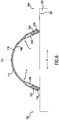
- a gas pressure (e.g., air) is delivered to the forming surface 101 of drum 100 so as to separate air impermeable layer 106 from surface 101.
- a gas pressure e.g., air
- small passages may be provided in drum 100 to supply a gas to the forming surface 101.
- air impermeable layer 106 will separate from forming surface 101 along the portion between bead elements 118 and 120 as shown.
- features associated with drum 100 are activated such that bead elements 118 and 120 are moved towards each other or axially inward as shown by arrows M.
- Such drum features may be activated so as to initiate the movement of bead elements 118 and 120 towards each other at the same time the delivery of the gas pressure is initiated.
- a predetermined interval of time may be allowed to lapse after initiating delivery of the gas pressure before initiating movement of the bead elements 118 and 120 towards each other using features of drum 100.
- reinforcing plies 112 and 114 allows air impermeable layer 106 to be forced against and simultaneously supported by plies 112 and 114,
- the perforations in plies 112 and 114 allow gas in cavity 116 to escape as air impermeable layer 106 moves towards plies 112 and 114 between e.g., the position shown in FIG. 5 and the position shown in FIG. 6 .
- the intermediate tire assembly 130 takes on a toroidal shape as shown in FIG. 7 .
- Protective sidewall rubber members can be added to side wall portions 128 and 130.
- a tread rubber (not shown) can be added to crown portion 132.
- the resulting intermediate tire assembly 132 can then be removed from forming drum 100 and placed into e.g., a curing press for molding and curing.
Landscapes
- Engineering & Computer Science (AREA)
- Mechanical Engineering (AREA)
- Tyre Moulding (AREA)
Claims (15)
- Procédé d'assemblage de composants de pneumatique sur un tambour de fabrication de pneumatique (100) ayant une surface de formage de forme cylindrique (101) s'étendant entre des côtés opposés (102, 104) du tambour, le tambour définissant des directions axiales et circonférentielles, le procédé comprenant les étapes de :couchage d'une ou plusieurs couches imperméables à l'air (106) sur la surface de formage ;positionnement d'une paire d'inserts de support de flanc (108, 110) sur les une ou plusieurs couches imperméables à l'air avec chaque insert de support de flanc espacé depuis un côté respectif du tambour ;placement d'au moins une nappe de renforcement (112) sur la paire d'inserts de support de flanc sur le tambour de façon à suspendre au-dessus de la surface de formage l'au moins une nappe de renforcement entre la paire d'inserts de support de flanc, dans lequel l'au moins une nappe de renforcement comprend une pluralité de perforations (126) positionnées centralement sur l'au moins une nappe de renforcement et espacées le long d'une direction longitudinale du tambour ;assemblage de l'au moins une nappe de renforcement sur la paire d'inserts de support de flanc et sur les une ou plusieurs couches imperméables à l'air en des emplacements axialement vers l'extérieur de chaque support de flanc en laissant la nappe de renforcement suspendue entre la paire d'inserts de support de flanc ;dépôt d'une paire de bourrages sur tringle (122, 124) sur l'au moins une nappe de renforcement avec chaque bourrage sur tringle espacé depuis un côté du tambour ;positionnement d'une paire d'éléments de talon circulaires (118, 120) sur le tambour avec chaque élément de talon positionné sur l'au moins une nappe de renforcement ;retournement des bords de l'au moins une nappe de renforcement sur la paire de bourrages sur tringle et la paire d'éléments de talon ;fourniture d'une pression de gaz sur la surface du tambour de formage de façon à séparer les une ou plusieurs couches imperméables à l'air de la surface de formage en des emplacements entre les éléments de talon ;déplacement des éléments de talon l'un vers l'autre le long de la direction axiale du tambour pendant ladite étape de fourniture d'une pression de gaz ; etutilisation de la pression de gaz pour pousser les une ou plusieurs couches imperméables à l'air loin de la surface de formage en des emplacements entre les éléments de talon et en contact avec les une ou plusieurs nappes de renforcement.
- Procédé d'assemblage de composants de pneumatique selon la revendication 1, comprenant en outre l'étape de :
permettre au gaz situé entre l'au moins une couche imperméable à l'air et l'au moins une nappe de renforcement de passer à travers les perforations dans l'au moins une nappe de renforcement pendant ladite étape de l'utilisation de la pression de gaz. - Procédé d'assemblage de composants de pneumatique selon la revendication 2, dans lequel ladite étape de fourniture et ladite étape de déplacement sont initiées simultanément.
- Procédé d'assemblage de composants de pneumatique selon la revendication 3, comprenant en outre l'étape de :
positionnement d'un caoutchouc de bande de roulement sur une partie de sommet de l'au moins une nappe de carcasse. - Procédé d'assemblage de composants de pneumatique selon la revendication 3, comprenant en outre l'étape de :
placement d'une paire d'éléments de caoutchouc de flanc sur des parties de flanc de l'au moins une nappe de carcasse. - Procédé d'assemblage de composants de pneumatique selon la revendication 1, comprenant en outre l'étape :
d'étirement des une ou plusieurs couches imperméables à l'air pendant ladite étape d'utilisation de la pression de gaz. - Procédé d'assemblage de composants de pneumatique selon la revendication 1, comprenant en outre l'étape de :
permettre au gaz situé entre l'au moins une couche imperméable à l'air et l'au moins une nappe de renforcement de passer à travers les perforations dans l'au moins une nappe de renforcement pendant ladite étape de fourniture. - Procédé d'assemblage de composants de pneumatique selon la revendication 1, comprenant en outre l'étape de création de la pluralité de perforations dans l'au moins une nappe de renforcement avant ladite étape de placement.
- Procédé d'assemblage de composants de pneumatique selon la revendication 1, dans lequel les perforations dans l'au moins une nappe de renforcement sont dans la plage d'environ 1,5 mm à environ 4,5 mm de diamètre.
- Procédé d'assemblage de composants de pneumatique selon la revendication 1, dans lequel les perforations dans l'au moins une nappe de renforcement ont environ 3 mm de diamètre.
- Procédé d'assemblage de composants de pneumatique selon la revendication 1, dans lequel les perforations dans l'au moins une nappe de renforcement sont positionnées dans une plage de 0 à environ 10 mm d'une ligne centrale de l'au moins une nappe de renforcement.
- Procédé d'assemblage de composants de pneumatique selon la revendication 1, dans lequel les une ou plusieurs couches imperméables à l'air comprennent deux couches imperméables à l'air.
- Procédé d'assemblage de composants de pneumatique selon la revendication 1, dans lequel les une ou plusieurs nappes de renforcement comprennent deux nappes de renforcement et dans lequel chacune des nappes comprend une pluralité de perforations positionnées centralement sur l'au moins une nappe de renforcement et espacées le long d'une direction circonférentielle du pneumatique à construire.
- Procédé d'assemblage de composants de pneumatique selon la revendication 1, dans lequel une première nappe de renforcement est positionnée sur la paire de supports de flanc pendant ladite étape de placement et comprenant en outre l'étape de fourniture d'une seconde nappe de renforcement sur la paire de supports de flanc après ladite étape de rotation.
- Procédé d'assemblage de composants de pneumatique selon la revendication 1, dans lequel l'étape de placement crée une cavité temporaire (116) s'étendant circonférentiellement autour du tambour entre les une ou plusieurs couches imperméables à l'air et l'au moins une nappe de renforcement.
Applications Claiming Priority (1)
| Application Number | Priority Date | Filing Date | Title |
|---|---|---|---|
| PCT/US2012/043456 WO2013191692A1 (fr) | 2012-06-21 | 2012-06-21 | Procédé permettant de coller un calandrage intérieur à une nappe de carcasse d'un pneu |
Publications (3)
| Publication Number | Publication Date |
|---|---|
| EP2864112A1 EP2864112A1 (fr) | 2015-04-29 |
| EP2864112A4 EP2864112A4 (fr) | 2016-03-30 |
| EP2864112B1 true EP2864112B1 (fr) | 2018-12-26 |
Family
ID=49769146
Family Applications (1)
| Application Number | Title | Priority Date | Filing Date |
|---|---|---|---|
| EP12879193.6A Active EP2864112B1 (fr) | 2012-06-21 | 2012-06-21 | Procédé permettant de coller un calandrage intérieur à une nappe de carcasse d'un pneu |
Country Status (5)
| Country | Link |
|---|---|
| US (1) | US9908302B2 (fr) |
| EP (1) | EP2864112B1 (fr) |
| KR (1) | KR101800170B1 (fr) |
| CN (1) | CN104411478B (fr) |
| WO (1) | WO2013191692A1 (fr) |
Families Citing this family (5)
| Publication number | Priority date | Publication date | Assignee | Title |
|---|---|---|---|---|
| JP6295812B2 (ja) * | 2014-05-09 | 2018-03-20 | 横浜ゴム株式会社 | ランフラットタイヤの製造方法および成形装置 |
| JP6683470B2 (ja) * | 2015-12-16 | 2020-04-22 | Toyo Tire株式会社 | タイヤの製造方法及び未加硫タイヤ |
| US10960627B2 (en) | 2017-09-01 | 2021-03-30 | The Goodyear Tire & Rubber Company | Method of making a tire |
| DE102020216103A1 (de) * | 2020-12-17 | 2022-06-23 | Continental Reifen Deutschland Gmbh | Verfahren zum Aufbauen eines Fahrzeugreifens mit inverser Seitenwand und Vorrichtung zur Durchführung eines solchen Verfahrens |
| KR20250008780A (ko) * | 2022-05-12 | 2025-01-15 | 리타이어 에이에스 | 타이어 베이스 층 접합 |
Citations (1)
| Publication number | Priority date | Publication date | Assignee | Title |
|---|---|---|---|---|
| JP2005119227A (ja) * | 2003-10-20 | 2005-05-12 | Yokohama Rubber Co Ltd:The | タイヤ成形方法 |
Family Cites Families (32)
| Publication number | Priority date | Publication date | Assignee | Title |
|---|---|---|---|---|
| US2409974A (en) * | 1942-08-06 | 1946-10-22 | Gen Tire & Rubber Co | Tire building machine |
| US2973799A (en) * | 1957-12-18 | 1961-03-07 | Goodrich Co B F | Vented rubberized fabric article and method of making same |
| US3722567A (en) * | 1970-12-15 | 1973-03-27 | Pneumatiques Caoutchouc Mfg | Radial-ply pneumatic tire |
| US4229246A (en) * | 1978-12-18 | 1980-10-21 | The Steelastic Company | Building drum assembly |
| US4226655A (en) * | 1979-01-02 | 1980-10-07 | The B. F. Goodrich Company | Method for building a tire |
| US4402783A (en) * | 1981-04-30 | 1983-09-06 | Nrm Corporation | Axially collapsible and expandable tire building drum |
| JPH05305682A (ja) | 1992-03-04 | 1993-11-19 | Bridgestone Corp | 円筒状部材均一拡径装置、円筒状部材拡径方法、円筒状部材均一拡径用ドラム及び円筒状部材均一拡縮装置 |
| JP2644168B2 (ja) * | 1993-07-14 | 1997-08-25 | 住友ゴム工業株式会社 | タイヤ成形機用フォーマ |
| CA2121159C (fr) | 1993-07-16 | 2005-03-29 | Kenneth Dean Conger | Tambour de fabrication de pneus profiles et fabrication de pneus |
| US6358346B1 (en) | 2000-07-28 | 2002-03-19 | The Goodyear Tire & Rubber Company | Method of building tire with composite ply structure |
| US6488797B1 (en) * | 2000-05-12 | 2002-12-03 | Bridgestone/Firestone North American Tire, Llc | First stage run flat tire building drum and method of using same |
| JP4603736B2 (ja) | 2001-09-06 | 2010-12-22 | 株式会社ブリヂストン | タイヤの製造方法 |
| US6769468B2 (en) | 2001-09-21 | 2004-08-03 | The Goodyear Tire & Rubber Company | Tire building drum having expandable center section and independently expandable bead lock assemblies in the end sections |
| EP1456007A1 (fr) * | 2001-12-19 | 2004-09-15 | Pirelli Pneumatici S.p.A. | Produit semi-fini elastomere destine a la production du calandrage interieur d'un pneumatique et pneumatique obtenu avec ce calandrage interieur |
| WO2003089258A1 (fr) * | 2002-04-19 | 2003-10-30 | Bridgestone Corporation | Pneumatique permettant le roulage a plat et procede de fabrication de ce pneumatique |
| FR2855043B1 (fr) | 2003-05-22 | 2006-08-11 | Oreal | Composition de maquillage pour la peau et plus particulierement une composition de type fond de teint fluide, dotee de qualites d'application optimisees |
| US20050028920A1 (en) * | 2003-08-04 | 2005-02-10 | Roedseth John Kolbjoern | High crown first stage tire building drum |
| JP2005238654A (ja) * | 2004-02-26 | 2005-09-08 | Sumitomo Rubber Ind Ltd | 生タイヤの製造方法 |
| WO2005105419A1 (fr) * | 2004-04-30 | 2005-11-10 | Pirelli Tyre S.P.A. | Procede de fabrication d'un pneu a flancs renforces pour roue de vehicule |
| DE102004032508A1 (de) | 2004-07-06 | 2006-02-16 | Continental Aktiengesellschaft | Verfahren und Vorrichtung zum Aufbau eines Radialreifens |
| JP4537806B2 (ja) * | 2004-08-31 | 2010-09-08 | 住友ゴム工業株式会社 | 空気入りタイヤ、及びその製造方法 |
| US7670449B2 (en) | 2005-11-22 | 2010-03-02 | The Goodyear Tire & Rubber Company | Method of manufacturing tire with turned down ply construction |
| DE602007000888D1 (de) * | 2006-06-16 | 2009-05-28 | Michelin Soc Tech | Verfahren zum Auflegen einer verstärkten Karkassenlage. |
| US8215356B2 (en) | 2006-12-21 | 2012-07-10 | The Goodyear Tire & Rubber Company | Tire with composite ply structure and envelope turnup |
| US20100024986A1 (en) * | 2007-02-14 | 2010-02-04 | Toyo Tire & Rubber Co., Ltd. | Perforating apparatus for tire constituent member |
| US8316903B2 (en) * | 2007-10-01 | 2012-11-27 | The Goodyear Tire & Rubber Company | Pneumatic tire having built-in sealant layer and preparation thereof |
| JP4989449B2 (ja) * | 2007-12-25 | 2012-08-01 | 横浜ゴム株式会社 | 空気入りタイヤの製造方法及び空気入りタイヤ |
| JP5305682B2 (ja) | 2008-02-15 | 2013-10-02 | 日本ぱちんこ部品株式会社 | 遊技機 |
| US8986480B2 (en) * | 2008-04-18 | 2015-03-24 | Pirelli Tyre S.P.A. | Process and apparatus for assembling tyres |
| JP5358681B2 (ja) * | 2008-05-28 | 2013-12-04 | ピレリ・タイヤ・ソチエタ・ペル・アツィオーニ | タイヤを構築する方法および装置 |
| US8205652B2 (en) | 2008-12-12 | 2012-06-26 | The Goodyear Tire & Rubber Company | Self-supporting pneumatic tire with optimized ply line |
| US8785028B1 (en) * | 2012-02-08 | 2014-07-22 | NTS Works, Inc. | High conductivity battery contact |
-
2012
- 2012-06-21 EP EP12879193.6A patent/EP2864112B1/fr active Active
- 2012-06-21 US US14/406,789 patent/US9908302B2/en active Active
- 2012-06-21 CN CN201280074063.0A patent/CN104411478B/zh active Active
- 2012-06-21 WO PCT/US2012/043456 patent/WO2013191692A1/fr not_active Ceased
- 2012-06-21 KR KR1020147035717A patent/KR101800170B1/ko active Active
Patent Citations (1)
| Publication number | Priority date | Publication date | Assignee | Title |
|---|---|---|---|---|
| JP2005119227A (ja) * | 2003-10-20 | 2005-05-12 | Yokohama Rubber Co Ltd:The | タイヤ成形方法 |
Also Published As
| Publication number | Publication date |
|---|---|
| WO2013191692A1 (fr) | 2013-12-27 |
| US9908302B2 (en) | 2018-03-06 |
| CN104411478B (zh) | 2017-05-10 |
| US20150165707A1 (en) | 2015-06-18 |
| KR20150022862A (ko) | 2015-03-04 |
| EP2864112A1 (fr) | 2015-04-29 |
| KR101800170B1 (ko) | 2017-11-22 |
| CN104411478A (zh) | 2015-03-11 |
| EP2864112A4 (fr) | 2016-03-30 |
Similar Documents
| Publication | Publication Date | Title |
|---|---|---|
| CN103587134B (zh) | 无套筒的轮胎成型鼓 | |
| JP4777585B2 (ja) | ランフラットタイヤ製造用の第1段階作成用ドラム及びその使用方法 | |
| EP2864112B1 (fr) | Procédé permettant de coller un calandrage intérieur à une nappe de carcasse d'un pneu | |
| US7241353B2 (en) | Method of manufacturing tire | |
| EP2923827B1 (fr) | Procédé de fabrication d'un pneu de motocyclette | |
| EP1793981B1 (fr) | Procede et installation de confection de pneumatiques | |
| CN104884239B (zh) | 用于构造车轮用轮胎的方法和设备 | |
| EP2239130B1 (fr) | Procédé de fabrication de pneu et pneu | |
| CN106142611B (zh) | 充气轮胎的制造方法、成型装置及充气轮胎 | |
| EP1793980A1 (fr) | Procede et appareil de fabrication de pneus | |
| JP2011230424A (ja) | グリーンタイヤの製造方法および、その方法に用いるサイドブラダー | |
| CN109421302B (zh) | 成型轮胎的方法 | |
| CN109421298B (zh) | 成型轮胎的方法 | |
| JP2005335081A (ja) | 空気入りタイヤの製造方法 | |
| US9290062B2 (en) | Tyre and tyre building method | |
| JP2019098640A (ja) | 空気入りタイヤの製造方法 | |
| JP6484107B2 (ja) | 生タイヤの形成方法 | |
| JP6533692B2 (ja) | 空気入りタイヤの製造方法、及びシェーピング装置 | |
| JP2005212278A (ja) | タイヤの製造方法 | |
| JP6510309B2 (ja) | 空気入りタイヤの製造方法、及びシェーピング装置 | |
| JP2006503727A (ja) | 車両ホイール用タイヤの製造方法及び装置 | |
| JP2019104111A (ja) | 空気入りタイヤの製造方法 | |
| CN109421305A (zh) | 充气轮胎的制造方法以及轮胎成型装置 | |
| JP2016049708A (ja) | タイヤ製造方法 |
Legal Events
| Date | Code | Title | Description |
|---|---|---|---|
| PUAI | Public reference made under article 153(3) epc to a published international application that has entered the european phase |
Free format text: ORIGINAL CODE: 0009012 |
|
| 17P | Request for examination filed |
Effective date: 20141212 |
|
| AK | Designated contracting states |
Kind code of ref document: A1 Designated state(s): AL AT BE BG CH CY CZ DE DK EE ES FI FR GB GR HR HU IE IS IT LI LT LU LV MC MK MT NL NO PL PT RO RS SE SI SK SM TR |
|
| AX | Request for extension of the european patent |
Extension state: BA ME |
|
| DAX | Request for extension of the european patent (deleted) | ||
| RA4 | Supplementary search report drawn up and despatched (corrected) |
Effective date: 20160225 |
|
| RIC1 | Information provided on ipc code assigned before grant |
Ipc: B29D 30/36 20060101AFI20160219BHEP Ipc: B29D 30/20 20060101ALI20160219BHEP Ipc: B29D 30/06 20060101ALN20160219BHEP |
|
| STAA | Information on the status of an ep patent application or granted ep patent |
Free format text: STATUS: EXAMINATION IS IN PROGRESS |
|
| 17Q | First examination report despatched |
Effective date: 20161201 |
|
| RAP1 | Party data changed (applicant data changed or rights of an application transferred) |
Owner name: COMPAGNIE GENERALE DES ETABLISSEMENTS MICHELIN |
|
| RAP1 | Party data changed (applicant data changed or rights of an application transferred) |
Owner name: COMPAGNIE GENERALE DES ETABLISSEMENTS MICHELIN |
|
| GRAP | Despatch of communication of intention to grant a patent |
Free format text: ORIGINAL CODE: EPIDOSNIGR1 |
|
| STAA | Information on the status of an ep patent application or granted ep patent |
Free format text: STATUS: GRANT OF PATENT IS INTENDED |
|
| RIC1 | Information provided on ipc code assigned before grant |
Ipc: B29D 30/06 20060101ALN20180717BHEP Ipc: B29D 30/20 20060101ALI20180717BHEP Ipc: B29D 30/36 20060101AFI20180717BHEP |
|
| INTG | Intention to grant announced |
Effective date: 20180802 |
|
| RAP1 | Party data changed (applicant data changed or rights of an application transferred) |
Owner name: COMPAGNIE GENERALE DES ETABLISSEMENTS MICHELIN |
|
| GRAS | Grant fee paid |
Free format text: ORIGINAL CODE: EPIDOSNIGR3 |
|
| GRAA | (expected) grant |
Free format text: ORIGINAL CODE: 0009210 |
|
| STAA | Information on the status of an ep patent application or granted ep patent |
Free format text: STATUS: THE PATENT HAS BEEN GRANTED |
|
| AK | Designated contracting states |
Kind code of ref document: B1 Designated state(s): AL AT BE BG CH CY CZ DE DK EE ES FI FR GB GR HR HU IE IS IT LI LT LU LV MC MK MT NL NO PL PT RO RS SE SI SK SM TR |
|
| REG | Reference to a national code |
Ref country code: GB Ref legal event code: FG4D |
|
| REG | Reference to a national code |
Ref country code: CH Ref legal event code: EP |
|
| REG | Reference to a national code |
Ref country code: AT Ref legal event code: REF Ref document number: 1080822 Country of ref document: AT Kind code of ref document: T Effective date: 20190115 |
|
| REG | Reference to a national code |
Ref country code: DE Ref legal event code: R096 Ref document number: 602012055308 Country of ref document: DE |
|
| REG | Reference to a national code |
Ref country code: IE Ref legal event code: FG4D |
|
| REG | Reference to a national code |
Ref country code: NL Ref legal event code: FP |
|
| PG25 | Lapsed in a contracting state [announced via postgrant information from national office to epo] |
Ref country code: LT Free format text: LAPSE BECAUSE OF FAILURE TO SUBMIT A TRANSLATION OF THE DESCRIPTION OR TO PAY THE FEE WITHIN THE PRESCRIBED TIME-LIMIT Effective date: 20181226 Ref country code: HR Free format text: LAPSE BECAUSE OF FAILURE TO SUBMIT A TRANSLATION OF THE DESCRIPTION OR TO PAY THE FEE WITHIN THE PRESCRIBED TIME-LIMIT Effective date: 20181226 Ref country code: BG Free format text: LAPSE BECAUSE OF FAILURE TO SUBMIT A TRANSLATION OF THE DESCRIPTION OR TO PAY THE FEE WITHIN THE PRESCRIBED TIME-LIMIT Effective date: 20190326 Ref country code: LV Free format text: LAPSE BECAUSE OF FAILURE TO SUBMIT A TRANSLATION OF THE DESCRIPTION OR TO PAY THE FEE WITHIN THE PRESCRIBED TIME-LIMIT Effective date: 20181226 Ref country code: FI Free format text: LAPSE BECAUSE OF FAILURE TO SUBMIT A TRANSLATION OF THE DESCRIPTION OR TO PAY THE FEE WITHIN THE PRESCRIBED TIME-LIMIT Effective date: 20181226 Ref country code: NO Free format text: LAPSE BECAUSE OF FAILURE TO SUBMIT A TRANSLATION OF THE DESCRIPTION OR TO PAY THE FEE WITHIN THE PRESCRIBED TIME-LIMIT Effective date: 20190326 |
|
| REG | Reference to a national code |
Ref country code: LT Ref legal event code: MG4D |
|
| PG25 | Lapsed in a contracting state [announced via postgrant information from national office to epo] |
Ref country code: GR Free format text: LAPSE BECAUSE OF FAILURE TO SUBMIT A TRANSLATION OF THE DESCRIPTION OR TO PAY THE FEE WITHIN THE PRESCRIBED TIME-LIMIT Effective date: 20190327 Ref country code: RS Free format text: LAPSE BECAUSE OF FAILURE TO SUBMIT A TRANSLATION OF THE DESCRIPTION OR TO PAY THE FEE WITHIN THE PRESCRIBED TIME-LIMIT Effective date: 20181226 Ref country code: AL Free format text: LAPSE BECAUSE OF FAILURE TO SUBMIT A TRANSLATION OF THE DESCRIPTION OR TO PAY THE FEE WITHIN THE PRESCRIBED TIME-LIMIT Effective date: 20181226 Ref country code: SE Free format text: LAPSE BECAUSE OF FAILURE TO SUBMIT A TRANSLATION OF THE DESCRIPTION OR TO PAY THE FEE WITHIN THE PRESCRIBED TIME-LIMIT Effective date: 20181226 |
|
| REG | Reference to a national code |
Ref country code: AT Ref legal event code: MK05 Ref document number: 1080822 Country of ref document: AT Kind code of ref document: T Effective date: 20181226 |
|
| PG25 | Lapsed in a contracting state [announced via postgrant information from national office to epo] |
Ref country code: PL Free format text: LAPSE BECAUSE OF FAILURE TO SUBMIT A TRANSLATION OF THE DESCRIPTION OR TO PAY THE FEE WITHIN THE PRESCRIBED TIME-LIMIT Effective date: 20181226 Ref country code: IT Free format text: LAPSE BECAUSE OF FAILURE TO SUBMIT A TRANSLATION OF THE DESCRIPTION OR TO PAY THE FEE WITHIN THE PRESCRIBED TIME-LIMIT Effective date: 20181226 Ref country code: CZ Free format text: LAPSE BECAUSE OF FAILURE TO SUBMIT A TRANSLATION OF THE DESCRIPTION OR TO PAY THE FEE WITHIN THE PRESCRIBED TIME-LIMIT Effective date: 20181226 Ref country code: PT Free format text: LAPSE BECAUSE OF FAILURE TO SUBMIT A TRANSLATION OF THE DESCRIPTION OR TO PAY THE FEE WITHIN THE PRESCRIBED TIME-LIMIT Effective date: 20190426 Ref country code: ES Free format text: LAPSE BECAUSE OF FAILURE TO SUBMIT A TRANSLATION OF THE DESCRIPTION OR TO PAY THE FEE WITHIN THE PRESCRIBED TIME-LIMIT Effective date: 20181226 |
|
| PG25 | Lapsed in a contracting state [announced via postgrant information from national office to epo] |
Ref country code: SK Free format text: LAPSE BECAUSE OF FAILURE TO SUBMIT A TRANSLATION OF THE DESCRIPTION OR TO PAY THE FEE WITHIN THE PRESCRIBED TIME-LIMIT Effective date: 20181226 Ref country code: EE Free format text: LAPSE BECAUSE OF FAILURE TO SUBMIT A TRANSLATION OF THE DESCRIPTION OR TO PAY THE FEE WITHIN THE PRESCRIBED TIME-LIMIT Effective date: 20181226 Ref country code: SM Free format text: LAPSE BECAUSE OF FAILURE TO SUBMIT A TRANSLATION OF THE DESCRIPTION OR TO PAY THE FEE WITHIN THE PRESCRIBED TIME-LIMIT Effective date: 20181226 Ref country code: IS Free format text: LAPSE BECAUSE OF FAILURE TO SUBMIT A TRANSLATION OF THE DESCRIPTION OR TO PAY THE FEE WITHIN THE PRESCRIBED TIME-LIMIT Effective date: 20190426 Ref country code: RO Free format text: LAPSE BECAUSE OF FAILURE TO SUBMIT A TRANSLATION OF THE DESCRIPTION OR TO PAY THE FEE WITHIN THE PRESCRIBED TIME-LIMIT Effective date: 20181226 |
|
| REG | Reference to a national code |
Ref country code: DE Ref legal event code: R097 Ref document number: 602012055308 Country of ref document: DE |
|
| PG25 | Lapsed in a contracting state [announced via postgrant information from national office to epo] |
Ref country code: DK Free format text: LAPSE BECAUSE OF FAILURE TO SUBMIT A TRANSLATION OF THE DESCRIPTION OR TO PAY THE FEE WITHIN THE PRESCRIBED TIME-LIMIT Effective date: 20181226 Ref country code: AT Free format text: LAPSE BECAUSE OF FAILURE TO SUBMIT A TRANSLATION OF THE DESCRIPTION OR TO PAY THE FEE WITHIN THE PRESCRIBED TIME-LIMIT Effective date: 20181226 |
|
| PLBE | No opposition filed within time limit |
Free format text: ORIGINAL CODE: 0009261 |
|
| STAA | Information on the status of an ep patent application or granted ep patent |
Free format text: STATUS: NO OPPOSITION FILED WITHIN TIME LIMIT |
|
| 26N | No opposition filed |
Effective date: 20190927 |
|
| PG25 | Lapsed in a contracting state [announced via postgrant information from national office to epo] |
Ref country code: MC Free format text: LAPSE BECAUSE OF FAILURE TO SUBMIT A TRANSLATION OF THE DESCRIPTION OR TO PAY THE FEE WITHIN THE PRESCRIBED TIME-LIMIT Effective date: 20181226 |
|
| REG | Reference to a national code |
Ref country code: CH Ref legal event code: PL |
|
| GBPC | Gb: european patent ceased through non-payment of renewal fee |
Effective date: 20190621 |
|
| PG25 | Lapsed in a contracting state [announced via postgrant information from national office to epo] |
Ref country code: SI Free format text: LAPSE BECAUSE OF FAILURE TO SUBMIT A TRANSLATION OF THE DESCRIPTION OR TO PAY THE FEE WITHIN THE PRESCRIBED TIME-LIMIT Effective date: 20181226 |
|
| REG | Reference to a national code |
Ref country code: BE Ref legal event code: MM Effective date: 20190630 |
|
| PG25 | Lapsed in a contracting state [announced via postgrant information from national office to epo] |
Ref country code: TR Free format text: LAPSE BECAUSE OF FAILURE TO SUBMIT A TRANSLATION OF THE DESCRIPTION OR TO PAY THE FEE WITHIN THE PRESCRIBED TIME-LIMIT Effective date: 20181226 |
|
| PG25 | Lapsed in a contracting state [announced via postgrant information from national office to epo] |
Ref country code: GB Free format text: LAPSE BECAUSE OF NON-PAYMENT OF DUE FEES Effective date: 20190621 Ref country code: IE Free format text: LAPSE BECAUSE OF NON-PAYMENT OF DUE FEES Effective date: 20190621 |
|
| PG25 | Lapsed in a contracting state [announced via postgrant information from national office to epo] |
Ref country code: LI Free format text: LAPSE BECAUSE OF NON-PAYMENT OF DUE FEES Effective date: 20190630 Ref country code: LU Free format text: LAPSE BECAUSE OF NON-PAYMENT OF DUE FEES Effective date: 20190621 Ref country code: BE Free format text: LAPSE BECAUSE OF NON-PAYMENT OF DUE FEES Effective date: 20190630 Ref country code: CH Free format text: LAPSE BECAUSE OF NON-PAYMENT OF DUE FEES Effective date: 20190630 |
|
| PG25 | Lapsed in a contracting state [announced via postgrant information from national office to epo] |
Ref country code: CY Free format text: LAPSE BECAUSE OF FAILURE TO SUBMIT A TRANSLATION OF THE DESCRIPTION OR TO PAY THE FEE WITHIN THE PRESCRIBED TIME-LIMIT Effective date: 20181226 |
|
| PG25 | Lapsed in a contracting state [announced via postgrant information from national office to epo] |
Ref country code: HU Free format text: LAPSE BECAUSE OF FAILURE TO SUBMIT A TRANSLATION OF THE DESCRIPTION OR TO PAY THE FEE WITHIN THE PRESCRIBED TIME-LIMIT; INVALID AB INITIO Effective date: 20120621 Ref country code: MT Free format text: LAPSE BECAUSE OF FAILURE TO SUBMIT A TRANSLATION OF THE DESCRIPTION OR TO PAY THE FEE WITHIN THE PRESCRIBED TIME-LIMIT Effective date: 20181226 |
|
| PG25 | Lapsed in a contracting state [announced via postgrant information from national office to epo] |
Ref country code: MK Free format text: LAPSE BECAUSE OF FAILURE TO SUBMIT A TRANSLATION OF THE DESCRIPTION OR TO PAY THE FEE WITHIN THE PRESCRIBED TIME-LIMIT Effective date: 20181226 |
|
| PGFP | Annual fee paid to national office [announced via postgrant information from national office to epo] |
Ref country code: NL Payment date: 20240619 Year of fee payment: 13 |
|
| PGFP | Annual fee paid to national office [announced via postgrant information from national office to epo] |
Ref country code: DE Payment date: 20250618 Year of fee payment: 14 |
|
| PGFP | Annual fee paid to national office [announced via postgrant information from national office to epo] |
Ref country code: FR Payment date: 20250625 Year of fee payment: 14 |
|
| REG | Reference to a national code |
Ref country code: NL Ref legal event code: MM Effective date: 20250701 |
|
| PG25 | Lapsed in a contracting state [announced via postgrant information from national office to epo] |
Ref country code: NL Free format text: LAPSE BECAUSE OF NON-PAYMENT OF DUE FEES Effective date: 20250701 |