EP2864199B1 - Dispositif à oxygène d'urgence dans les toilettes d'avion - Google Patents
Dispositif à oxygène d'urgence dans les toilettes d'avion Download PDFInfo
- Publication number
- EP2864199B1 EP2864199B1 EP13737717.2A EP13737717A EP2864199B1 EP 2864199 B1 EP2864199 B1 EP 2864199B1 EP 13737717 A EP13737717 A EP 13737717A EP 2864199 B1 EP2864199 B1 EP 2864199B1
- Authority
- EP
- European Patent Office
- Prior art keywords
- oxygen
- flow
- aircraft
- air pressure
- breathing mask
- Prior art date
- Legal status (The legal status is an assumption and is not a legal conclusion. Google has not performed a legal analysis and makes no representation as to the accuracy of the status listed.)
- Active
Links
Images





Classifications
-
- A—HUMAN NECESSITIES
- A62—LIFE-SAVING; FIRE-FIGHTING
- A62B—DEVICES, APPARATUS OR METHODS FOR LIFE-SAVING
- A62B7/00—Respiratory apparatus
- A62B7/14—Respiratory apparatus for high-altitude aircraft
-
- B—PERFORMING OPERATIONS; TRANSPORTING
- B64—AIRCRAFT; AVIATION; COSMONAUTICS
- B64D—EQUIPMENT FOR FITTING IN OR TO AIRCRAFT; FLIGHT SUITS; PARACHUTES; ARRANGEMENT OR MOUNTING OF POWER PLANTS OR PROPULSION TRANSMISSIONS IN AIRCRAFT
- B64D11/00—Passenger or crew accommodation; Flight-deck installations not otherwise provided for
-
- B—PERFORMING OPERATIONS; TRANSPORTING
- B64—AIRCRAFT; AVIATION; COSMONAUTICS
- B64D—EQUIPMENT FOR FITTING IN OR TO AIRCRAFT; FLIGHT SUITS; PARACHUTES; ARRANGEMENT OR MOUNTING OF POWER PLANTS OR PROPULSION TRANSMISSIONS IN AIRCRAFT
- B64D2231/00—Emergency oxygen systems
- B64D2231/02—Supply or distribution systems
-
- B—PERFORMING OPERATIONS; TRANSPORTING
- B64—AIRCRAFT; AVIATION; COSMONAUTICS
- B64D—EQUIPMENT FOR FITTING IN OR TO AIRCRAFT; FLIGHT SUITS; PARACHUTES; ARRANGEMENT OR MOUNTING OF POWER PLANTS OR PROPULSION TRANSMISSIONS IN AIRCRAFT
- B64D2231/00—Emergency oxygen systems
- B64D2231/02—Supply or distribution systems
- B64D2231/025—Oxygen masks; Mask storages; Features related to mask deployment
-
- Y—GENERAL TAGGING OF NEW TECHNOLOGICAL DEVELOPMENTS; GENERAL TAGGING OF CROSS-SECTIONAL TECHNOLOGIES SPANNING OVER SEVERAL SECTIONS OF THE IPC; TECHNICAL SUBJECTS COVERED BY FORMER USPC CROSS-REFERENCE ART COLLECTIONS [XRACs] AND DIGESTS
- Y02—TECHNOLOGIES OR APPLICATIONS FOR MITIGATION OR ADAPTATION AGAINST CLIMATE CHANGE
- Y02T—CLIMATE CHANGE MITIGATION TECHNOLOGIES RELATED TO TRANSPORTATION
- Y02T50/00—Aeronautics or air transport
- Y02T50/40—Weight reduction
Definitions
- the present invention generally relates to emergency oxygen supply systems such as are routinely carried on commercial aircraft for deployment upon loss of cabin pressure. More particularly, the invention pertains to enhancing the efficiency with which the supplied oxygen is used to thereby reduce the total amount of oxygen that needs to be carried on an aircraft.
- Emergency oxygen supply systems are commonly installed on aircraft for the purpose of supplying oxygen to passengers upon loss of cabin pressure at altitudes above about 3048m (10,000 feet).
- Such systems typically include a face mask adapted to fit over the mouth and nose which is released from an overhead storage compartment when needed.
- Supplemental oxygen delivered by the mask increases the level of blood oxygen saturation in the mask user beyond what would be experienced if ambient air were breathed at the prevailing cabin pressure altitude condition.
- the flow of oxygen provided thereby is calculated to be sufficient to sustain all passengers until cabin pressure is reestablished or until a lower, safer altitude can be reached.
- Each such face mask has a reservoir bag attached thereto into which a constant flow of oxygen is directed upon deployment of the system and upon activation of the individual face mask via a pull cord.
- the oxygen is supplied continuously at a rate that is calculated to accommodate a worst case scenario, namely to satisfy the need of a passenger with a significantly larger than average tidal volume who is breathing at a faster than average respiration rate when cabin pressure is lost at maximum cruising altitude.
- a total of three valves that are associated with the mask serve to coordinate flows between the bag and the mask, and between the mask and the surroundings.
- An inhalation valve serves to confine the oxygen flowing into the bag to the bag while the passenger is exhaling as well as during the post-expiratory pause and at all times also prevents any flow from the mask into the bag.
- the inhalation valve opens to allow for the inhalation of the oxygen that has accumulated in the bag.
- the dilution valve opens to allow cabin air to be drawn into the mask.
- the continuing flow of oxygen into the bag and through the open inhalation valve into the mask is thereby diluted by the cabin air that is inhaled during the balance of the inhalation phase.
- the exhalation valve opens to allow a free flow from the mask into the surroundings while the inhalation valve closes to prevent flow from the mask back into the bag. All three valves remain closed during the post-expiratory pause while oxygen continues to flow into the reservoir bag.
- An emergency oxygen supply system for use on aircraft in the event of a loss in cabin pressure is configured for delivering allotments of oxygen and timing the delivery such allotments to each passenger so as maximize the efficiency of the transfer of such oxygen into the passenger's bloodstream.
- the delivery of each allotment is selected so that the entire allotment is available for inhalation into the region of the lung most efficient at oxygen transfer while the volume of the allotment is selected to substantially coincide with the volume of such region of the lung.
- the chemical reaction in chemical oxygen generators is exothermic, so that heat released by a chemical oxygen generator needs to be managed in the aircraft installation. Heat can damage nearby aircraft components, and management of the heat adds cost and weight to an aircraft installation.
- AD 2011-04-09 airworthiness directive 2011-04-09 was issued by the FAA requiring the removal or disabling of chemical oxygen generators from aircraft lavatories. This AD is in conflict with FAR 25.1447 requiring supplemental emergency oxygen to be available in aircraft lavatories.
- an aircraft emergency oxygen dispensing device to dispense supplemental oxygen suitable for breathing generates substantially no heat in operation, and that resolves the conflict between the FAA airworthiness and the regulation requiring supplemental emergency oxygen to be available in aircraft lavatories, by providing a stored source of oxygen as an alternative to chemical oxygen generators for aircraft lavatories.
- an aircraft emergency oxygen dispensing device that reduces the quantity of oxygen that must be stored, thereby reducing the weight of the system. It would also be desirable to provide such an aircraft emergency oxygen dispensing device that is configured to fit within the dimensional envelope of an existing aircraft oxygen generator, allowing the device to be retrofit as a direct replacement in size, weight and function for an existing aircraft chemical oxygen generator, to reduce or eliminate the need to alter existing installations in aircraft. It would also be desirable to provide such an aircraft emergency oxygen dispensing device that operates substantially in the same manner as an aircraft chemical oxygen generator, and that can be used by an aircraft passenger or crew in the same manner as an aircraft chemical oxygen generator, thereby eliminating the need for additional or new training and explanation by flight crews. The present invention meets these and other needs.
- US 2012/111871 relates to a stored oxygen system that can release pure oxygen to aircraft crew and passengers with an extended life period that does not require frequent verification of status when installed in an aircraft.
- the present invention provides for an aircraft emergency oxygen dispensing device for use in aircraft cabin to dispense supplemental oxygen suitable for breathing by a user in small quantities, that resolves the conflict between the FAA airworthiness and the regulation requiring supplemental emergency oxygen to be available in aircraft lavatories by providing a non-chemical source of oxygen for aircraft lavatories, generating substantially no heat in operation, reducing or eliminating the heat management concerns of a chemical oxygen generator, and requiring less oxygen, thus reducing the quantity of oxygen that must be stored, and reducing the weight of the system.
- the oxygen storage vessel and hardware are small enough to fit within the dimensional envelope of an oxygen generator, so that the device can be used as a direct replacement in size, weight and function for an aircraft chemical oxygen generator.
- the present invention accordingly provides for an aircraft emergency oxygen dispensing device according to claim 1.
- the pressure seal is a rupture disc formed of frangible material capable of being fractured to open the oxygen storage vessel and initiate the flow of oxygen from the oxygen storage vessel.
- the initiator includes a lance configured to mechanically break the rupture disc. In another presently preferred aspect, the initiator is configured to be manually activated. In another presently preferred aspect, the initiator includes a lever configured to be manually turned to advance the lance to mechanically break the pressure seal. In another presently preferred aspect, the initiator is configured to be electronically activated.
- the flow controller is configured to rapidly supply oxygen at an initial altitude and throughout at least a portion of subsequent descent of the aircraft.
- the aircraft emergency oxygen dispensing device includes a container housing covering at least a portion of the oxygen storage vessel, the manifold, the pressure regulator, the one or more flow control valves, and the flow controller.
- the container housing covers at least a portion of the power supply.
- the aircraft emergency oxygen dispensing device includes an ambient cabin air pressure sensor connected to the flow controller and configured to detect the ambient cabin air pressure in the aircraft and generate a cabin air pressure signal indicating the ambient cabin air pressure in the aircraft, and wherein the container housing covers at least a portion of the ambient cabin air pressure sensor.
- the flow controller is configured to control the one or more flow control valves to modulate the flow of oxygen to flow continuously to the one or more breathing masks. In another presently preferred aspect, the flow controller is configured to control the one or more flow control valves to modulate the flow of oxygen to flow continuously to the one or more breathing masks based upon the ambient cabin air pressure signal.
- the at least one breathing mask air pressure sensor detects a differential vacuum pressure created by a user inhaling through the one or more breathing masks, the at least one breathing mask air pressure sensor is configured to generate a differential vacuum pressure signal, and the one or more flow control valves are controlled by the flow controller responsive to the differential vacuum pressure signal.
- the at least one breathing mask air pressure sensor is disposed in the one or more breathing masks.
- the breathing mask air pressure sensor may be an electro-pneumatic sensor.
- the present invention provides for an aircraft lavatory emergency oxygen device for use in civilian and military airplanes to provide supplemental oxygen suitable for breathing by a user in small quantities.
- the aircraft lavatory emergency oxygen device of the invention preferably is a non- chemical, self-contained oxygen dispensing device that is configured and dimensioned to fit into an existing space allocated for a chemical oxygen generator, allowing the aircraft lavatory emergency oxygen device of the invention to be retrofit into existing chemical oxygen generator systems.
- the invention also incorporates electronic controls, a power supply and hardware to dispense the gaseous oxygen in small quantities.
- the storage vessel and controls are incorporated into a single container to replace traditional chemical oxygen generators or to provide supplemental oxygen in an aircraft lavatory or other airplane locations. Self-containment in a single package makes retrofitting the design possible.
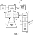
- the present invention accordingly provides for an aircraft lavatory emergency oxygen device 10 for use in civilian and military airplanes to provide supplemental oxygen suitable for breathing.
- the device includes a small, high pressure oxygen storage vessel 12 for storing high pressure gaseous oxygen that preferably is sealed by a pressure seal 14 to prevent flow from the oxygen storage vessel until the pressure seal is broken.
- the pressure seal also provides overpressure protection for the vessel.
- the pressure seal may, for example, be a rupture disc formed of frangible material capable of being fractured to open the oxygen storage vessel and initiate the flow of oxygen from the oxygen storage vessel.
- the pressure in the small, high pressure oxygen storage vessel is typically approximately 20.68MPa (3000 psi), for example, although other similar storage pressures may also be suitable.
- a manifold 16 is connected in fluid communication with the oxygen storage vessel and a pressure regulator 18 that is connected in fluid communication with the manifold to receive the flow of oxygen at the high, first oxygen pressure from the oxygen storage vessel through the manifold.
- the pressure regulator is configured to deliver the flow of oxygen at a second oxygen pressure lower than the first oxygen pressure.
- the lower, second oxygen pressure is 0.11 MPa (16 psig), although similar lower oxygen pressures may also be suitable.
- the pressure seal of the oxygen storage vessel is disposed in the manifold, as will be explained further hereinbelow.
- One or more flow control valves 20 are connected in fluid communication with the pressure regulator, and a flow controller 22 is connected to the one or more flow control valves to control the operation of the one or more flow control valves.
- the flow controller typically is preferably electronic, and may be constructed of one or more printed circuit boards (PCB), for example.
- the flow controller preferably is configured to rapidly supply oxygen at an initial altitude, such as 9144m (30,000 ft.) or greater, for example, and throughout at least a portion of subsequent descent of the aircraft, such as above 3048m (10,000 ft.), for example, typically for periods of approximately 12-22 minutes, for one or more persons, for example.
- the aircraft lavatory emergency oxygen device preferably includes a power supply 24 disposed within the container housing that is configured to provide power to the flow controller and the one or more flow control valves.
- the power supply can be a small battery pack including a one or more batteries, although the device can alternatively use another type of power supply, such as an external battery, for example, or a connection to an aircraft power supply, to obtain the required power.
- the manifold includes an initiator 26 is configured to break the pressure seal to initiate a flow of oxygen from the oxygen storage vessel, and receives a flow of oxygen from the oxygen storage vessel at a first oxygen pressure.
- the initiator preferably includes a lance 28 configured to mechanically break the rupture disc.
- the initiator can be a sealed electro-pyrotechnic actuator 30 that can be electronically activated.
- Other devices for fracturing the rupture disc may alternatively be suitable, as long as an appropriate pressure seal can be maintained downstream of the oxygen storage vessel and opened as desired.
- the aircraft lavatory emergency oxygen device preferably includes an ambient cabin air pressure sensor 34 connected to the flow controller and disposed within the container housing.
- the ambient cabin air pressure sensor is typically a transducer connected to the PCB of the flow controller, and is configured to detect the ambient cabin air pressure in the aircraft and generate an ambient cabin air pressure signal 36 indicating the ambient cabin air pressure in the aircraft.
- the one or more flow control valves each have a flow control valve outlet 38, and receive and meter the flow of oxygen at the second oxygen pressure from the pressure regulator to one or more breathing masks 40, each of which is connected to a corresponding flow control valve outlet, by metering small quantities of oxygen to the one or more breathing masks by a pulse oxygen system, in which the flow controller is configured to receive the ambient cabin air pressure signal from the ambient cabin air pressure sensor in the aircraft, and determine what quantity of oxygen is to be provided to the one or more breathing masks, to control operation of the one or more flow control valves responsive to the ambient cabin air pressure signal.
- the small quantities of oxygen that are metered to the one or more breathing masks that are less than that typically provided by a chemical oxygen generator, while an equivalent level of hypoxia protection is provided by the pulse oxygen system in aircraft decompression events.
- the pulse oxygen system typically adjusts an allotment of oxygen to each individual user as function of the user's actual demand for oxygen, such as according to a user's respiration rate, for example, wherein faster breathing results in a faster delivery rate of the user's oxygen allotments, such as is described in U.S. Patent 7,588,032 .
- One or more breathing masks are typically connected to receive the flow of oxygen at the second oxygen pressure from the one or more flow control valves, and a breathing mask air pressure sensor 46, such as an electro-pneumatic sensor, typically connected to the breathing mask, or disposed in the breathing mask, for example, monitors the breathing of the user, and is connected to the flow controller, so that the one or more flow control valves can be controlled by the flow controller responsive to the breathing mask air pressure sensor.
- the one or more flow control valves are configured to limit the flow of oxygen to the one or more breathing masks to a period of time during each respiratory cycle of the user that is sufficient to allow only a preselected volume of oxygen to flow to the one or more breathing masks during each respiratory cycle of the user.
- the one or more flow control valves may be a solenoid valve, for example, for switching the flow of oxygen to the one or more breathing masks for the period of time during each respiratory cycle of the user responsive to a breathing mask air pressure signal from a pressure sensor configured to detect a pressure within the one or more breathing masks.
- the breathing mask air pressure sensor detects a differential vacuum pressure created by a user inhaling through the one or more breathing masks and generates a differential vacuum pressure signal 48 received by the flow controller, so that the one or more flow control valves can be controlled by the flow controller responsive to the differential vacuum pressure signal.
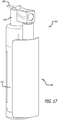
- the aircraft lavatory emergency oxygen device preferably includes a container housing, protective cover portion, shroud or assembly cap 50 that covers the assembly of the flow controller, flow and pressure control components, and power supply, to seal and protect the components.
- the container housing, protective cover portion, shroud or assembly cap is typically generally tubular, and typically can be approx. 69.85mm (2 3/4 inch) diameter, approx. 203.2mm (8 inch) length, for example.
- the combined assembly of the container housing portion or assembly capsule and storage vessel is dimensioned to be retrofit in an existing space envelope allocated for a chemical oxygen generator in an aircraft.
- the oxygen storage vessel is a single use oxygen storage vessel, although the oxygen storage vessel may alternatively be a rechargeable oxygen storage vessel.
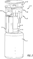
- the present invention provides for an aircraft lavatory emergency oxygen device 110 for use in civilian and military airplanes to provide supplemental oxygen suitable for breathing.
- the device includes a small oxygen storage vessel 112 for storing high pressure gaseous oxygen that preferably is sealed by a pressure seal 114 to prevent flow from the oxygen storage vessel until the pressure seal is broken.
- the pressure seal may, for example, be a rupture disc formed of frangible material capable of being fractured to open the oxygen storage vessel and initiate the flow of oxygen from the oxygen storage vessel.
- a manifold 116 is connected in fluid communication with the oxygen storage vessel and a pressure regulator 118 that is connected in fluid communication with the manifold to receive the flow of oxygen at the high, first oxygen pressure from the oxygen storage vessel through the manifold.
- the pressure regulator is configured to deliver the flow of oxygen at a second oxygen pressure lower than the first oxygen pressure.
- the second oxygen pressure is 0.11 MPa (16 psig).
- the pressure seal is disposed in the manifold.
- One or more flow control valves 120 are connected in fluid communication with the pressure regulator, and a flow controller 122 is connected to the one or more flow control valves to control the operation of the one or more flow control valves.
- the flow controller typically is configured to rapidly supply oxygen at an initial altitude, such as 9144m (30,000 ft.) or greater, for example, and throughout at least a portion of subsequent descent of the aircraft, such as above 3048m (10,000 ft.), for example, typically for periods of approximately 12-22 minutes, for one or more persons, for example.
- the aircraft lavatory emergency oxygen device includes a power supply 124 that is configured to provide power to the flow controller and the one or more flow control valves, and the power supply can be disposed in or protected by the container housing, for example, as will be explained further below.
- the power supply can be a small battery pack including a one or more batteries, although the device can alternatively use another type of power supply, such as an external battery, for example, or a connection to an aircraft power supply, to obtain the required power.
- the manifold includes an initiator 126 configured to break the pressure seal to initiate a flow of oxygen from the oxygen storage vessel, and receives a flow of oxygen from the oxygen storage vessel at a first oxygen pressure.
- the initiator preferably includes a lance 128 configured to mechanically break the rupture disc.
- the initiator can be configured to be manually activated, such as by turning a lever 132 to advance the lance to mechanically break the pressure seal, or by turning a wheel to advance the lance to mechanically break the pressure seal.
- Other devices for fracturing the rupture disc may alternatively be suitable, as long as an appropriate pressure seal can be maintained downstream of the oxygen storage vessel and opened as desired.
- the aircraft lavatory emergency oxygen device preferably includes an ambient cabin air pressure sensor 134 connected to the flow controller and disposed within the container housing.
- the ambient cabin air pressure sensor is typically a transducer connected to the PCB of the flow controller, and is configured to detect the ambient cabin air pressure in the aircraft and generate an ambient cabin air pressure signal 136 indicating the ambient cabin air pressure in the aircraft.
- the one or more flow control valves each have a flow control valve outlet 138, and receive and meter the flow of oxygen at the second oxygen pressure from the pressure regulator to one or more breathing masks 140, each of which is connected to a corresponding flow control valve outlet, by metering small quantities of oxygen to the one or more breathing masks by a pulse oxygen system, in which the flow controller receives the ambient cabin air pressure signal from the ambient cabin air pressure sensor in the aircraft, and determines what quantity of oxygen is to be provided to the one or more breathing masks to control operation of the one or more flow control valves responsive to the ambient cabin air pressure signal.
- the small quantities of oxygen that are metered to the one or more breathing masks that are less than that typically provided by a chemical oxygen generator, while an equivalent level of hypoxia protection is provided by the pulse oxygen system in aircraft decompression events.
- the pulse oxygen system typically adjusts an allotment of oxygen to each individual user as function of the user's actual demand for oxygen, such as according to a user's respiration rate, for example, wherein faster breathing results in a faster delivery rate of the user's oxygen allotments, such as is described in U.S. Patent 7,588,032 .
- the one or more flow control valves are configured to limit the flow of oxygen to the one or more breathing masks to a period of time during each respiratory cycle of the user that is sufficient to allow only a preselected volume of oxygen to flow to the one or more breathing masks during each respiratory cycle of the user.
- the one or more flow control valves may be a solenoid valve, for example, for switching the flow of oxygen to the one or more breathing masks for the period of time during each respiratory cycle of the user responsive to a breathing mask air pressure signal from a pressure sensor configured to detect a pressure within the one or more breathing masks.
- One or more breathing masks are typically connected to receive the flow of oxygen at the second oxygen pressure from the one or more flow control valves, and a breathing mask air pressure sensor 146, such as an electro-pneumatic sensor typically connected to the breathing mask, or disposed in the breathing mask, for example, monitors the breathing of the user, and is connected to the flow controller, so that the one or more flow control valves can be controlled by the flow controller responsive to the breathing mask air pressure sensor.
- the breathing mask air pressure sensor detects a differential vacuum pressure created by a user inhaling through the one or more breathing masks and generates a differential vacuum pressure signal 148 received by the flow controller, so that the one or more flow control valves can be controlled by the flow controller responsive to the differential vacuum pressure signal.
- a container housing, protective cover portion, shroud or assembly cap 150 covers the oxygen storage vessel, flow controller, flow and pressure control components and power supply, to seal and protect the components, and typically can be approx. 69.85mm (2 3/4 inch) diameter, approx. 203.2mm (8 inch) length, for example.
- the combined assembly of the container housing portion or assembly capsule and storage vessel is dimensioned to be retrofit in an existing space envelope allocated for a chemical oxygen generator in an aircraft.
- the oxygen storage vessel is a single use oxygen storage vessel, although the oxygen storage vessel may alternatively be a rechargeable oxygen storage vessel.
- the one or more flow control valves are configured to modulate the flow of oxygen to flow continuously to one or more breathing masks, such as by a modulated oxygen system (MOS).
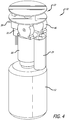
- the aircraft lavatory emergency oxygen device 210 includes a small oxygen storage vessel 212 for storing high pressure gaseous oxygen that preferably is sealed by a pressure seal 214 to prevent flow from the oxygen storage vessel until the pressure seal is broken.
- the pressure seal may, for example, be a rupture disc formed of frangible material capable of being fractured to open the oxygen storage vessel and initiate the flow of oxygen from the oxygen storage vessel.
- a manifold 216 is connected in fluid communication with the oxygen storage vessel, and a pressure regulator 218 is connected in fluid communication with the manifold to receive the flow of oxygen at the first oxygen pressure through the manifold.
- the pressure regulator is configured to deliver the flow of oxygen at a second oxygen pressure lower than the first oxygen pressure.
- the second oxygen pressure is 0.11 MPa (16 psig).
- One or more flow control valves 220 are connected in fluid communication with the pressure regulator, and a flow controller 222 is connected to the one or more flow control valves for controlling the operation of the one or more flow control valves.
- the flow controller typically is configured to rapidly supply oxygen at an initial altitude, such as 9144m (30,000 ft.) or greater, for example, and throughout at least a portion of subsequent descent of the aircraft, such as above 3048m (10,000 ft.), for example, typically for periods of approximately 12-22 minutes, for one or more persons, for example.
- the pressure seal is disposed in the manifold.
- the aircraft lavatory emergency oxygen device includes a power supply 224 configured to provide power to the flow controller and the one or more flow control valves is provided, and the power supply can be disposed in or protected by the container housing, for example, as will be explained further below.
- the power supply can be a small battery pack including a one or more batteries, although the device can alternatively use another type of power supply, such as an external battery, for example, or a connection to an aircraft power supply, to obtain the required power.
- the manifold includes an initiator 226 configured to break the pressure seal to initiate a flow of oxygen from the oxygen storage vessel, and receives a flow of oxygen from the oxygen storage vessel at a first oxygen pressure.
- the initiator preferably includes a lance 228 configured to mechanically break the rupture disc.
- the initiator can be a sealed electro-pyrotechnic actuator 230 that can be electronically activated.
- Other devices for fracturing the rupture disc may alternatively be suitable, as long as an appropriate pressure seal can be maintained downstream of the oxygen storage vessel and opened as desired.
- the aircraft lavatory emergency oxygen device preferably includes an ambient cabin air pressure sensor 234 connected to the flow controller and disposed within the container housing.
- the ambient cabin air pressure sensor is typically a transducer connected to the PCB of the flow controller, and is configured to detect the ambient cabin air pressure in the aircraft and generate an ambient cabin air pressure signal 236 indicating the ambient cabin air pressure in the aircraft.
- the one or more flow control valves each have a flow control valve outlet 238, and receive and meter the flow of oxygen at the second oxygen pressure from the pressure regulator to one or more breathing masks 240, each of which is connected to a corresponding flow control valve outlet, by metering small quantities of oxygen to the one or more breathing masks by a pulse oxygen system, in which the flow controller receives the ambient cabin air pressure signal from an ambient cabin air pressure sensor in the aircraft, and determines what quantity of oxygen is to be provided to the one or more breathing masks to control operation of the one or more flow control valves responsive to the ambient cabin air pressure signal.
- the one or more flow control valves are configured to modulate the flow of oxygen to flow continuously to the one or more breathing masks based upon an ambient cabin air pressure in the aircraft.
- one or more inlet valves may by on-off inlet valves, such as two-position solenoid valves, or one or more electrically operated valves that are capable of assuming a multiplicity of states between fully open and fully closed, for example, which in combination with suitable sensors and suitable control logic, can operate efficiently at a range of altitudes.
- These technologies utilize less oxygen than a chemical oxygen generator to provide an equivalent level of hypoxia protection in aircraft decompression events.
- a container housing, protective cover portion, shroud or assembly cap 250 covers the flow controller, flow and pressure control components and power supply, to seal and protect the components, and is typically generally tubular, and typically can be approx. 69.85 (2 3/4) inch diameter, approx. 203.2mm (8 inch) length, for example.
- the combined assembly of the container housing portion or assembly capsule and storage vessel is dimensioned to be retrofit in an existing space envelope allocated for a chemical oxygen generator in an aircraft.
- the oxygen storage vessel is a single use oxygen storage vessel, although the oxygen storage vessel may alternatively be a rechargeable oxygen storage vessel.
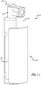
- the present invention provides for an aircraft lavatory emergency oxygen device 310 that includes a small oxygen storage vessel 312 for storing high pressure gaseous oxygen that preferably is sealed by a pressure seal 314 to prevent flow from the oxygen storage vessel until the pressure seal is broken.
- the pressure seal may, for example, be a rupture disc formed of frangible material capable of being fractured to open the oxygen storage vessel and initiate the flow of oxygen from the oxygen storage vessel.
- the aircraft lavatory emergency oxygen device includes a manifold 316 connected in fluid communication with the oxygen storage vessel, and a pressure regulator 318 is connected in fluid communication with the manifold to receive the flow of oxygen at the first oxygen pressure through the manifold.
- the pressure regulator is configured to deliver the flow of oxygen at a second oxygen pressure lower than the first oxygen pressure.
- the second oxygen pressure is 0.11 MPa (16 psig).
- the pressure seal is disposed in the manifold.
- the aircraft lavatory emergency oxygen device includes one or more flow control valves 320 connected in fluid communication with the pressure regulator, and a flow controller 322 is connected to the one or more flow control valves.
- the flow controller typically is configured to rapidly supply oxygen at an initial altitude, such as 9144m (30,000 ft.) or greater, for example, and throughout at least a portion of subsequent descent of the aircraft, such as above 3048m (10,000 ft.), for example, typically for periods of approximately 12-22 minutes, for one or more persons, for example.
- the aircraft lavatory emergency oxygen device includes a power supply 324 configured to provide power to the flow controller and the one or more flow control valves, and the power supply can be disposed in or protected by the container housing, for example, as will be explained further below.
- the power supply can be a small battery pack including a one or more batteries, although the device can alternatively use another type of power supply, such as an external battery, for example, or a connection to an aircraft power supply, to obtain the required power.
- the manifold includes an initiator 326 configured to break the pressure seal to initiate a flow of oxygen from the oxygen storage vessel, and receives a flow of oxygen from the oxygen storage vessel at a first oxygen pressure.
- the initiator preferably includes a lance 328 configured to mechanically break the rupture disc.
- the initiator can be configured to be manually activated, such as by turning a lever 332 to advance the lance to mechanically break the pressure seal, or by turning a wheel to advance the lance to mechanically break the pressure seal.
- Other devices for fracturing the rupture disc may alternatively be suitable, as long as an appropriate pressure seal can be maintained downstream of the oxygen storage vessel and opened as desired.
- the aircraft lavatory emergency oxygen device preferably includes an ambient cabin air pressure sensor 334 connected to the flow controller and disposed within the container housing.
- the ambient cabin air pressure sensor is typically a transducer connected to the PCB of the flow controller, and is configured to detect the ambient cabin air pressure in the aircraft and generate an ambient cabin air pressure signal 336 indicating the ambient cabin air pressure in the aircraft.
- the one or more flow control valves each have a flow control valve outlet 338, and receive and meter the flow of oxygen at the second oxygen pressure from the pressure regulator to one or more breathing masks 340.
- the one or more flow control valves are configured to modulate the flow of oxygen to flow continuously to the one or more breathing masks, such as by a modulated oxygen system (MOS).
- MOS modulated oxygen system
- the one or more flow control valves are configured to modulate the flow of oxygen to flow continuously to the one or more breathing masks based upon an ambient cabin air pressure in the aircraft.
- the one or more inlet valves may by on-off inlet valves, such as two-position solenoid valves, or one or more electrically operated valves that are capable of assuming a multiplicity of states between fully open and fully closed, for example, which in combination with suitable sensors and suitable control logic, can operate efficiently at a range of altitudes.
- the aircraft lavatory emergency oxygen device preferably includes a container housing, protective cover portion, shroud or assembly cap 350 that covers the oxygen storage vessel, flow controller, flow and pressure control components and power supply, to seal and protect the components, and typically can be approx. 69.85mm (2 3/4 inch) diameter, approx. 203.2mm (8 inch) length, for example.
- the combined assembly of the container housing portion or assembly capsule and storage vessel is dimensioned to be retrofit in an existing space envelope allocated for a chemical oxygen generator in an aircraft.
- the oxygen storage vessel is a single use oxygen storage vessel, although the oxygen storage vessel may alternatively be a rechargeable oxygen storage vessel.
- the aircraft lavatory emergency oxygen device of the invention operates in the same manner as a chemical oxygen generator, in the sense that a breathing mask attached to the aircraft lavatory emergency oxygen device is drawn to a passenger's face and donned the same as a breathing mask attached to a chemical oxygen generator, so that to a user, the oxygen masks look and operate the same as in existing oxygen equipment.
- the immediate application of the invention is to replace chemical oxygen generators installed in aircraft lavatories.
- the aircraft lavatory emergency oxygen device of the invention can also be used to replace chemical oxygen generators in passenger service unit (PSU) panels over cabin seats, and in other aircraft locations, such as over flight attendant seats, and in crew rest areas, for example.
- PSU passenger service unit
- the aircraft lavatory emergency oxygen device includes one or more flow control valves 320 connected in fluid communication with the pressure regulator, and a flow controller 322 is connected to the one or more flow control valves.
- the flow controller typically is configured to rapidly supply oxygen at an initial altitude, such as 30,000 ft. or greater, for example, and throughout at least a portion of subsequent descent of the aircraft, such as above 10,000 ft., for example, typically for periods of approximately 12-22 minutes, for one or more persons, for example.
- the aircraft lavatory emergency oxygen device includes a power supply 324 configured to provide power to the flow controller and the one or more flow control valves, and the power supply can be disposed in or protected by the container housing, for example, as will be explained further below.
- the power supply can be a small battery pack including a one or more batteries, although the device can alternatively use another type of power supply, such as an external battery, for example, or a connection to an aircraft power supply, to obtain the required power.
- the manifold includes an initiator 326 configured to break the pressure seal to initiate a flow of oxygen from the oxygen storage vessel, and receives a flow of oxygen from the oxygen storage vessel at a first oxygen pressure.
- the initiator preferably includes a lance 328 configured to mechanically break the rupture disc.
- the initiator can be configured to be manually activated, such as by turning a lever 332 to advance the lance to mechanically break the pressure seal, or by turning a wheel to advance the lance to mechanically break the pressure seal.
- Other devices for fracturing the rupture disc may alternatively be suitable, as long as an appropriate pressure seal can be maintained downstream of the oxygen storage vessel and opened as desired.
- the aircraft lavatory emergency oxygen device preferably includes an ambient cabin air pressure sensor 334 connected to the flow controller and disposed within the container housing.
- the ambient cabin air pressure sensor is typically a transducer connected to the PCB of the flow controller, and is configured to detect the ambient cabin air pressure in the aircraft and generate an ambient cabin air pressure signal 336 indicating the ambient cabin air pressure in the aircraft.
- the one or more flow control valves each have a flow control valve outlet 338, and receive and meter the flow of oxygen at the second oxygen pressure from the pressure regulator to one or more breathing masks 340.
- the one or more flow control valves are configured to modulate the flow of oxygen to flow continuously to the one or more breathing masks, such as by a modulated oxygen system (MOS).
- MOS modulated oxygen system
- the one or more flow control valves are configured to modulate the flow of oxygen to flow continuously to the one or more breathing masks based upon an ambient cabin air pressure in the aircraft.
- the one or more inlet valves may by on-off inlet valves, such as two-position solenoid valves, or one or more electrically operated valves that are capable of assuming a multiplicity of states between fully open and fully closed, for example, which in combination with suitable sensors and suitable control logic, can operate efficiently at a range of altitudes.
- the aircraft lavatory emergency oxygen device preferably includes a container housing, protective cover portion, shroud or assembly cap 350 that covers the oxygen storage vessel, flow controller, flow and pressure control components and power supply, to seal and protect the components, and typically can be approx. 2 3 ⁇ 4 inch diameter, approx. 8 inch length, for example.
- the combined assembly of the container housing portion or assembly capsule and storage vessel is dimensioned to be retrofit in an existing space envelope allocated for a chemical oxygen generator in an aircraft.
- the oxygen storage vessel is a single use oxygen storage vessel, although the oxygen storage vessel may alternatively be a rechargeable oxygen storage vessel.
- the aircraft lavatory emergency oxygen device of the invention operates in the same manner as a chemical oxygen generator, in the sense that a breathing mask attached to the aircraft lavatory emergency oxygen device is drawn to a passenger's face and donned the same as a breathing mask attached to a chemical oxygen generator, so that to a user, the oxygen masks look and operate the same as in existing oxygen equipment.
- the immediate application of the invention is to replace chemical oxygen generators installed in aircraft lavatories.
- the aircraft lavatory emergency oxygen device of the invention can also be used to replace chemical oxygen generators in passenger service unit (PSU) panels over cabin seats, and in other aircraft locations, such as over flight attendant seats, and in crew rest areas, for example.
- PSU passenger service unit
Landscapes
- Health & Medical Sciences (AREA)
- Pulmonology (AREA)
- General Health & Medical Sciences (AREA)
- Business, Economics & Management (AREA)
- Emergency Management (AREA)
- Engineering & Computer Science (AREA)
- Aviation & Aerospace Engineering (AREA)
- Respiratory Apparatuses And Protective Means (AREA)
- Filling Or Discharging Of Gas Storage Vessels (AREA)
Claims (15)
- Dispositif de distribution d'oxygène d'urgence d'aéronef (10, 110, 210, 310) destiné à être utilisé dans une cabine d'aéronef pour distribuer de l'oxygène d'appoint approprié pour la respiration par un utilisateur en petites quantités, comprenant :un réservoir de stockage d'oxygène (12, 112, 212, 312) configuré pour stocker de l'oxygène gazeux ayant une pureté appropriée pour la respiration, ledit réservoir de stockage d'oxygène (12, 112, 212, 312) étant scellé par un joint d'étanchéité (14, 114, 214, 314) susceptible d'être rompu, ledit joint d'étanchéité (14, 114, 214, 314) étant configuré pour assurer l'étanchéité par rapport à un écoulement provenant dudit réservoir de stockage d'oxygène (12, 112, 212, 312) jusqu'à ce que ledit joint d'étanchéité (14, 114, 214, 314) soit rompu ;un collecteur (16, 116, 216, 316) relié en communication fluidique avec ledit réservoir de stockage d'oxygène (12, 112, 212, 312) et configuré pour recevoir un flux d'oxygène à partir dudit réservoir de stockage d'oxygène (12, 112, 212, 312) ayant une première pression d'oxygène, et ledit collecteur (16, 116, 216, 316) comportant un initiateur (26, 126, 226, 326) configuré pour rompre ledit joint d'étanchéité (14, 114, 214, 314) afin d'initier un écoulement d'oxygène à partir dudit réservoir de stockage d'oxygène (12, 112, 212, 312) ;un régulateur de pression (18, 118, 218, 318) relié en communication fluidique avec ledit collecteur (16, 116, 216, 316) pour recevoir un flux d'oxygène à partir dudit réservoir de stockage d'oxygène (12, 112, 212, 312) à travers ledit collecteur (16, 116, 216, 316) ayant une première pression d'oxygène, ledit régulateur de pression (18, 118, 218, 318) étant configuré pour délivrer le flux d'oxygène à une deuxième pression d'oxygène inférieure à ladite première pression d'oxygène ;au moins un masque respiratoire (40, 140, 240, 340) ;au moins une vanne de régulation de débit (20, 120, 220, 320) reliée en communication fluidique avec ledit régulateur de pression (18, 118, 218, 318) pour recevoir et mesurer le flux d'oxygène à la deuxième pression d'oxygène du régulateur de pression (18, 118, 218, 318) à l'au moins un masque respiratoire (40, 140, 240, 340), où l'au moins un masque respiratoire (40, 140, 240, 340) est relié pour recevoir le flux d'oxygène à la deuxième pression d'oxygène à partir de ladite au moins une vanne de régulation de débit (20, 120, 220, 320) ; etun régulateur de débit (22, 122, 222, 322) relié à ladite au moins une vanne de régulation de débit (20, 120, 220, 320), ledit régulateur de débit (22, 122, 222, 322) étant configuré de manière à être relié pour recevoir un signal de pression d'air ambiant de cabine (36, 136, 236, 336) à partir d'un capteur de pression d'air ambiant de cabine (34, 134, 234, 334) indiquant une pression d'air ambiant de cabine dans l'aéronef, ledit régulateur (22, 122, 222, 322) étant configuré pour déterminer une quantité d'oxygène à fournir à l'au moins un masque respiratoire (40, 140, 240, 340) afin de commander le fonctionnement de ladite au moins une vanne de régulation de débit (20, 120, 220, 320) en réponse au signal de pression d'air ambiant de cabine (36, 136, 236, 336) ; caractérisé en ce que le dispositif comprend en outre au moins un capteur de pression d'air de masque respiratoire (46) :ledit au moins un masque respiratoire (40, 140, 240, 340) étant relié à l'au moins un capteur de pression d'air de masque respiratoire (46) qui surveille la respiration de l'utilisateur, ledit au moins un capteur de pression d'air de masque respiratoire (46) étant configuré pour générer un signal de pression d'air de masque respiratoire (48, 148) indiquant une pression dans l'au moins un masque respiratoire (40, 140, 240, 340), ledit au moins un capteur de pression d'air de masque respiratoire (46) étant relié audit régulateur de débit (22, 122, 222, 322), et ladite au moins une vanne de régulation de débit (20, 120, 220, 320) étant commandée par ledit régulateur de débit (22, 122, 222, 322) en réponse audit au moins un capteur de pression d'air de masque respiratoire (46), et ledit régulateur de débit (22, 122, 222, 322) étant relié pour recevoir ledit signal de pression d'air de masque respiratoire (48, 148) ;dans lequel ledit régulateur de débit (22, 122, 222, 322) est configuré pour commander ladite au moins une vanne de régulation de débit (20, 120, 220, 320) afin de commuter l'écoulement d'oxygène vers l'au moins un masque respiratoire (40, 140, 240, 340) pendant une durée au cours d'un cycle respiratoire de l'utilisateur qui est suffisante pour permettre uniquement à un volume présélectionné d'oxygène de s'écouler vers l'au moins un masque respiratoire (40, 140, 240, 340) pendant le cycle respiratoire de l'utilisateur en réponse audit signal de pression d'air de masque respiratoire (48, 148), et où ladite au moins une vanne de régulation de débit (20, 120, 220, 320) est configurée pour limiter l'écoulement d'oxygène vers l'au moins un masque respiratoire (40, 140, 240, 340) à une durée au cours d'un cycle respiratoire de l'utilisateur qui est suffisante pour permettre uniquement à un volume présélectionné d'oxygène de s'écouler vers l'au moins un masque respiratoire (40, 140, 240, 340) au cours du cycle respiratoire de l'utilisateur ; et en ce que le dispositif comprend en outre :une alimentation électrique (24, 124, 224, 324) configurée pour fournir de l'énergie audit régulateur de débit (22, 122, 222, 322) et à ladite au moins une vanne de régulation de débit (20, 120, 220, 320).
- Dispositif de distribution d'oxygène d'urgence d'aéronef (10, 110, 210, 310) de la revendication 1, comprenant en outre un logement (50, 150, 250, 350) recouvrant au moins une partie dudit réservoir de stockage d'oxygène (12, 112, 212), dudit collecteur (16, 116, 216, 316), dudit régulateur de pression (18, 118, 218, 318), de ladite au moins une vanne de régulation de débit (20, 120, 220, 320) et dudit régulateur de débit (22, 122, 222, 322).
- Dispositif de distribution d'oxygène d'urgence d'aéronef (10, 110, 210, 310) de la revendication 1, dans lequel ledit joint d'étanchéité (14, 114, 214, 314) comprend un disque de rupture formé d'un matériau frangible susceptible d'être fracturé pour ouvrir le réservoir de stockage d'oxygène (12, 112, 212, 312) et initier l'écoulement d'oxygène à partir dudit réservoir de stockage d'oxygène (12, 112, 212, 312).
- Dispositif de distribution d'oxygène d'urgence d'aéronef (10, 110, 210, 310) de la revendication 1, dans lequel ledit initiateur (26, 126, 226, 326) comprend une lance configurée pour rompre mécaniquement le disque de rupture.
- Dispositif de distribution d'oxygène d'urgence d'aéronef de la revendication 1, dans lequel ledit initiateur (26, 126, 226, 326) est configuré pour être activé manuellement.
- Dispositif de distribution d'oxygène d'urgence d'aéronef (10, 110, 210, 310) de la revendication 1, dans lequel ledit initiateur (26, 126, 226, 326) comprend en outre un levier configuré pour être tourné manuellement afin de faire avancer ladite lance pour rompre mécaniquement ledit joint d'étanchéité (14, 114, 214, 314).
- Dispositif de distribution d'oxygène d'urgence d'aéronef (10, 110, 210, 310) de la revendication 1, dans lequel ledit initiateur (26, 126, 226, 326) est configuré pour être activé électroniquement.
- Dispositif de distribution d'oxygène d'urgence d'aéronef (10, 110, 210, 310) de la revendication 1, dans lequel ledit joint d'étanchéité (14, 114, 214, 314) est disposé dans ledit collecteur (16, 116, 216, 316).
- Dispositif de distribution d'oxygène d'urgence d'aéronef (10, 110, 210, 310) de la revendication 1, dans lequel ledit régulateur de débit (22, 122, 222, 322) et ladite au moins une vanne de régulation de débit (20, 120, 220, 320) sont configurés pour mesurer une petite quantité d'oxygène à l'au moins un masque respiratoire (40, 140, 240, 340) en fonction de la demande en oxygène de l'utilisateur.
- Dispositif de distribution d'oxygène d'urgence d'aéronef (10, 110, 210, 310) de la revendication 1, dans lequel ledit régulateur de débit (22, 122, 222, 322) est configuré pour commander ladite au moins une vanne de régulation de débit (20, 120, 220, 320) afin de moduler le flux d'oxygène de manière à s'écouler en continu vers l'au moins un masque respiratoire (40, 140, 240, 340).
- Dispositif de distribution d'oxygène d'urgence d'aéronef (10, 110, 210, 310) de la revendication 1, dans lequel ledit régulateur de débit (22, 122, 222, 322) est configuré pour commander ladite au moins une vanne de régulation de débit (20, 120, 220, 320) afin de moduler le flux d'oxygène de manière à s'écouler en continu vers l'au moins un masque respiratoire (40, 140, 240, 340) sur la base du signal de pression d'air ambiant de cabine (36, 136, 236, 336).
- Dispositif de distribution d'oxygène d'urgence d'aéronef (10, 110, 210, 310) de la revendication 1, dans lequel ledit régulateur de débit (22, 122, 222, 322) est configuré pour fournir rapidement de l'oxygène à une altitude initiale et tout au long d'au moins une partie d'une descente ultérieure de l'aéronef.
- Dispositif de distribution d'oxygène d'urgence d'aéronef (10, 110, 210, 310) de la revendication 2, dans lequel ledit logement (50, 150, 250, 350) recouvre au moins une partie de ladite alimentation électrique (24, 124, 224, 324).
- Dispositif de distribution d'oxygène d'urgence d'aéronef (10, 110, 210, 310) de la revendication 2, comprenant en outre le capteur de pression d'air ambiant de cabine relié audit régulateur de débit et configuré pour détecter la pression d'air ambiant de cabine dans l'aéronef et générer un signal de pression d'air de cabine indiquant la pression d'air ambiant de cabine dans l'aéronef, où ledit logement (50, 150, 250, 350) recouvre au moins une partie dudit capteur de pression d'air ambiant de cabine (34, 134, 234, 334).
- Dispositif de distribution d'oxygène d'urgence d'aéronef (10, 110, 210, 310) de la revendication 1, dans lequel ledit au moins un capteur de pression d'air de masque respiratoire (46) détecte une pression de vide différentielle créée par un utilisateur inhalant à travers ledit au moins un masque de respiration (40, 140, 240, 340), ledit au moins un capteur de pression d'air de masque respiratoire (46) étant configuré pour générer un signal de pression de vide différentielle, et ladite au moins une vanne de régulation de débit (20, 120, 220, 320) étant commandée par ledit régulateur de débit (22, 122, 222, 322) en réponse audit signal de pression de vide différentielle.
Applications Claiming Priority (2)
| Application Number | Priority Date | Filing Date | Title |
|---|---|---|---|
| US13/528,414 US10293193B2 (en) | 2012-06-20 | 2012-06-20 | Aircraft lavatory emergency oxygen device |
| PCT/US2013/045995 WO2013192047A1 (fr) | 2012-06-20 | 2013-06-14 | Dispositif à oxygène d'urgence dans les toilettes d'avion |
Publications (2)
| Publication Number | Publication Date |
|---|---|
| EP2864199A1 EP2864199A1 (fr) | 2015-04-29 |
| EP2864199B1 true EP2864199B1 (fr) | 2018-04-25 |
Family
ID=48794183
Family Applications (1)
| Application Number | Title | Priority Date | Filing Date |
|---|---|---|---|
| EP13737717.2A Active EP2864199B1 (fr) | 2012-06-20 | 2013-06-14 | Dispositif à oxygène d'urgence dans les toilettes d'avion |
Country Status (6)
| Country | Link |
|---|---|
| US (1) | US10293193B2 (fr) |
| EP (1) | EP2864199B1 (fr) |
| JP (1) | JP6067847B2 (fr) |
| CN (1) | CN104520190B (fr) |
| CA (1) | CA2876202C (fr) |
| WO (1) | WO2013192047A1 (fr) |
Families Citing this family (11)
| Publication number | Priority date | Publication date | Assignee | Title |
|---|---|---|---|---|
| EP3454929B1 (fr) | 2016-05-13 | 2023-08-30 | Lynntech, Inc. | Dispositif d'entraînement à l'hypoxie |
| EP3988177B1 (fr) | 2018-01-23 | 2025-07-16 | Safran Aerosystems | Systèmes d'oxygène dosé ayant des fonctions antiblocage de tube de distribution |
| US11338158B2 (en) | 2018-03-15 | 2022-05-24 | Safran Aerotechnics Sas | System and a method for delivering breathing gas to passengers on-board an aircraft |
| CA3040714A1 (fr) * | 2018-04-18 | 2019-10-18 | Zodiac Aerotechnics | Un systeme d'oxygene d'urgence destine a un aeronef equipe d'un dispositif de commutation et une methode d'exploitation d'un systeme d'oxygene d'urgence |
| WO2019217289A1 (fr) * | 2018-05-09 | 2019-11-14 | Lynntech, Inc. | Dispositif d'entraînement en hypoxie |
| CN111388891A (zh) * | 2020-03-19 | 2020-07-10 | 中国商用飞机有限责任公司 | 分舱布置的应急氧气装置 |
| US12329997B2 (en) * | 2020-03-26 | 2025-06-17 | The Boeing Company | Apparatus, system, and method for pressure altitude-compensating breath-controlled oxygen release |
| EP4146352B1 (fr) * | 2020-05-07 | 2025-11-12 | Aviation Works Limited | Appareil à circuit fermé |
| US12053654B2 (en) * | 2021-01-12 | 2024-08-06 | B/E Aerospace, Inc. | Pulsed oxygen delivery system and method for a closed breathing environment |
| CN115123548A (zh) * | 2022-06-15 | 2022-09-30 | 中国人民解放军空军工程大学航空机务士官学校 | 一种飞行器供氧调节装置 |
| CN115929956B (zh) * | 2023-01-06 | 2026-01-27 | 成都康拓兴业科技有限责任公司 | 用于高空吸氧系统的基准气压双控式建压机构 |
Family Cites Families (24)
| Publication number | Priority date | Publication date | Assignee | Title |
|---|---|---|---|---|
| US2324389A (en) * | 1941-03-17 | 1943-07-13 | Air Reduction | Portable oxygen aviation unit |
| US3521627A (en) * | 1968-01-23 | 1970-07-28 | Koch & Sons Inc H | Automatic emergency breathing oxygen system for aircraft |
| US4827964A (en) * | 1987-04-23 | 1989-05-09 | Mine Safety Appliances Company | System for metering of breathing gas for accommodation of breathing demand |
| US5531807A (en) * | 1994-11-30 | 1996-07-02 | Airsep Corporation | Apparatus and method for supplying oxygen to passengers on board aircraft |
| US5803062A (en) | 1996-05-14 | 1998-09-08 | Nellcor Puritan Bennett Inc. | Compression molded integrated personal service and oxygen modules for use in transport aircraft with improved mask repacking and test access |
| US6526967B2 (en) * | 2001-06-11 | 2003-03-04 | Be Intellectual Property, Inc. | Crew oxygen mask stowage assembly including selective depressurization valve |
| FR2855812B1 (fr) * | 2003-06-05 | 2005-07-22 | Air Liquide | Systeme embarque de generation et de fourniture d'oxygene et d'azote |
| DE102004026649A1 (de) | 2004-06-01 | 2006-01-05 | DRäGER AEROSPACE GMBH | Sauerstoffnotversorgungseinrichtung |
| US7588032B2 (en) | 2004-12-08 | 2009-09-15 | Be Intellectual Proeprty, Inc. | Oxygen conservation system for commercial aircraft |
| DE102004063698B4 (de) * | 2004-12-28 | 2010-02-04 | Dae Systems Gmbh | Notsauerstoffsystem für Flugzeugpassagiere |
| EP2004294B1 (fr) * | 2006-04-13 | 2010-07-21 | Intertechnique | Circuit d'alimentation en gaz respiratoire destine a un avion transportant des passagers |
| DE102006024052B4 (de) * | 2006-05-23 | 2014-09-25 | B/E Aerospace Systems Gmbh | Flugzeugsauerstoffversorgungseinheit |
| ES2340094T3 (es) * | 2006-08-10 | 2010-05-28 | Intertechnique | Mascarilla respiratoria con un arnes hinchable autonomo. |
| US20080072907A1 (en) * | 2006-09-22 | 2008-03-27 | Inogen Corporation | Oxygen conserver design for general aviation |
| DE102007031043B4 (de) * | 2007-07-04 | 2014-04-10 | B/E Aerospace Systems Gmbh | Sauerstoffversorgungseinrichtung |
| US20090188504A1 (en) | 2008-01-25 | 2009-07-30 | Siska Jr William D | Mechanically actuated emergency oxygen delivery system |
| US8016232B2 (en) | 2008-05-29 | 2011-09-13 | Honeywell International Inc. | Aircraft cabin pressure descent detection and control system and method |
| EP2151263B1 (fr) | 2008-08-04 | 2014-03-05 | Intertechnique | Dispositif de respiration d'oxygène dans un cockpit |
| CA2697592C (fr) * | 2009-04-08 | 2013-11-05 | Anurag Sharma H K | Dispositif de regulation de la dilution d'oxygene, reglable en fonction de la demande, pour utilisation dans des aeronefs |
| US8863743B2 (en) | 2009-07-16 | 2014-10-21 | Ametek Ameron, Llc | Hermetically welded sealed oxygen cylinder assembly and method of charging |
| US20110041853A1 (en) * | 2009-08-21 | 2011-02-24 | Intertechnique, S.A. | Circuit for supplying a respiratory gas to an aircraft passenger from a pressurized source comprising a pressure regulating unit |
| GB0919818D0 (en) * | 2009-09-16 | 2009-12-30 | Airbus Operations Ltd | Adaptable oxygen regulator system and method with an electronic control device |
| US9126063B2 (en) * | 2010-10-26 | 2015-09-08 | Zodiac Aerotechnics | Oxygen breathing device with integrated flexible buffer |
| US9669177B2 (en) * | 2011-05-19 | 2017-06-06 | Dennis R. Coleman | Voice responsive fluid delivery, controlling and monitoring system and method |
-
2012
- 2012-06-20 US US13/528,414 patent/US10293193B2/en active Active
-
2013
- 2013-06-14 EP EP13737717.2A patent/EP2864199B1/fr active Active
- 2013-06-14 JP JP2015518469A patent/JP6067847B2/ja active Active
- 2013-06-14 CN CN201380032732.2A patent/CN104520190B/zh active Active
- 2013-06-14 WO PCT/US2013/045995 patent/WO2013192047A1/fr not_active Ceased
- 2013-06-14 CA CA2876202A patent/CA2876202C/fr active Active
Non-Patent Citations (1)
| Title |
|---|
| None * |
Also Published As
| Publication number | Publication date |
|---|---|
| JP2015526127A (ja) | 2015-09-10 |
| JP6067847B2 (ja) | 2017-01-25 |
| CN104520190A (zh) | 2015-04-15 |
| US10293193B2 (en) | 2019-05-21 |
| CA2876202A1 (fr) | 2013-12-27 |
| CN104520190B (zh) | 2018-06-12 |
| US20130340760A1 (en) | 2013-12-26 |
| CA2876202C (fr) | 2020-07-28 |
| EP2864199A1 (fr) | 2015-04-29 |
| WO2013192047A1 (fr) | 2013-12-27 |
Similar Documents
| Publication | Publication Date | Title |
|---|---|---|
| EP2864199B1 (fr) | Dispositif à oxygène d'urgence dans les toilettes d'avion | |
| EP2514398B1 (fr) | Systeme de conservation d'oxygene pour un avion commercial | |
| EP2247340B1 (fr) | Circuit d'oxygène de bord d'aéronefs utilisant des systèmes de génération d'oxygène embarqués | |
| US12329997B2 (en) | Apparatus, system, and method for pressure altitude-compensating breath-controlled oxygen release | |
| WO2008097569A1 (fr) | Masque à oxygène pourvu d'une poche de réinhalation destiné à être utilisé avec une administration pulsée d'oxygène | |
| EP2089112B1 (fr) | Circuit d'alimentation en gaz respiratoire destiné à alimenter en oxygène les membres d'équipage et les passagers d'un aéronef | |
| US20250303202A1 (en) | Apparatus, System, and Method for Pressure Altitude-Compensating Breath-Controlled Oxygen Release | |
| EP3344321B1 (fr) | Dispositif de demande en gaz, procédé d'installation, système de distribution de gaz, et procédé d'utilisation | |
| Gradwell | Oxygen equipment and pressure clothing |
Legal Events
| Date | Code | Title | Description |
|---|---|---|---|
| PUAI | Public reference made under article 153(3) epc to a published international application that has entered the european phase |
Free format text: ORIGINAL CODE: 0009012 |
|
| 17P | Request for examination filed |
Effective date: 20141211 |
|
| AK | Designated contracting states |
Kind code of ref document: A1 Designated state(s): AL AT BE BG CH CY CZ DE DK EE ES FI FR GB GR HR HU IE IS IT LI LT LU LV MC MK MT NL NO PL PT RO RS SE SI SK SM TR |
|
| AX | Request for extension of the european patent |
Extension state: BA ME |
|
| DAX | Request for extension of the european patent (deleted) | ||
| 17Q | First examination report despatched |
Effective date: 20161202 |
|
| REG | Reference to a national code |
Ref country code: DE Ref legal event code: R079 Ref document number: 602013036471 Country of ref document: DE Free format text: PREVIOUS MAIN CLASS: B64D0013000000 Ipc: B64D0011000000 |
|
| GRAP | Despatch of communication of intention to grant a patent |
Free format text: ORIGINAL CODE: EPIDOSNIGR1 |
|
| RIC1 | Information provided on ipc code assigned before grant |
Ipc: A62B 7/14 20060101ALI20170831BHEP Ipc: B64D 11/00 20060101AFI20170831BHEP |
|
| INTG | Intention to grant announced |
Effective date: 20171004 |
|
| GRAS | Grant fee paid |
Free format text: ORIGINAL CODE: EPIDOSNIGR3 |
|
| GRAA | (expected) grant |
Free format text: ORIGINAL CODE: 0009210 |
|
| RAP1 | Party data changed (applicant data changed or rights of an application transferred) |
Owner name: B/E AEROSPACE, INC. |
|
| AK | Designated contracting states |
Kind code of ref document: B1 Designated state(s): AL AT BE BG CH CY CZ DE DK EE ES FI FR GB GR HR HU IE IS IT LI LT LU LV MC MK MT NL NO PL PT RO RS SE SI SK SM TR |
|
| REG | Reference to a national code |
Ref country code: GB Ref legal event code: FG4D |
|
| REG | Reference to a national code |
Ref country code: CH Ref legal event code: EP |
|
| REG | Reference to a national code |
Ref country code: AT Ref legal event code: REF Ref document number: 992592 Country of ref document: AT Kind code of ref document: T Effective date: 20180515 |
|
| REG | Reference to a national code |
Ref country code: IE Ref legal event code: FG4D |
|
| REG | Reference to a national code |
Ref country code: DE Ref legal event code: R096 Ref document number: 602013036471 Country of ref document: DE |
|
| REG | Reference to a national code |
Ref country code: NL Ref legal event code: FP |
|
| REG | Reference to a national code |
Ref country code: FR Ref legal event code: PLFP Year of fee payment: 6 |
|
| REG | Reference to a national code |
Ref country code: LT Ref legal event code: MG4D |
|
| PG25 | Lapsed in a contracting state [announced via postgrant information from national office to epo] |
Ref country code: NO Free format text: LAPSE BECAUSE OF FAILURE TO SUBMIT A TRANSLATION OF THE DESCRIPTION OR TO PAY THE FEE WITHIN THE PRESCRIBED TIME-LIMIT Effective date: 20180725 Ref country code: FI Free format text: LAPSE BECAUSE OF FAILURE TO SUBMIT A TRANSLATION OF THE DESCRIPTION OR TO PAY THE FEE WITHIN THE PRESCRIBED TIME-LIMIT Effective date: 20180425 Ref country code: BG Free format text: LAPSE BECAUSE OF FAILURE TO SUBMIT A TRANSLATION OF THE DESCRIPTION OR TO PAY THE FEE WITHIN THE PRESCRIBED TIME-LIMIT Effective date: 20180725 Ref country code: PL Free format text: LAPSE BECAUSE OF FAILURE TO SUBMIT A TRANSLATION OF THE DESCRIPTION OR TO PAY THE FEE WITHIN THE PRESCRIBED TIME-LIMIT Effective date: 20180425 Ref country code: LT Free format text: LAPSE BECAUSE OF FAILURE TO SUBMIT A TRANSLATION OF THE DESCRIPTION OR TO PAY THE FEE WITHIN THE PRESCRIBED TIME-LIMIT Effective date: 20180425 Ref country code: ES Free format text: LAPSE BECAUSE OF FAILURE TO SUBMIT A TRANSLATION OF THE DESCRIPTION OR TO PAY THE FEE WITHIN THE PRESCRIBED TIME-LIMIT Effective date: 20180425 Ref country code: SE Free format text: LAPSE BECAUSE OF FAILURE TO SUBMIT A TRANSLATION OF THE DESCRIPTION OR TO PAY THE FEE WITHIN THE PRESCRIBED TIME-LIMIT Effective date: 20180425 |
|
| PG25 | Lapsed in a contracting state [announced via postgrant information from national office to epo] |
Ref country code: LV Free format text: LAPSE BECAUSE OF FAILURE TO SUBMIT A TRANSLATION OF THE DESCRIPTION OR TO PAY THE FEE WITHIN THE PRESCRIBED TIME-LIMIT Effective date: 20180425 Ref country code: HR Free format text: LAPSE BECAUSE OF FAILURE TO SUBMIT A TRANSLATION OF THE DESCRIPTION OR TO PAY THE FEE WITHIN THE PRESCRIBED TIME-LIMIT Effective date: 20180425 Ref country code: RS Free format text: LAPSE BECAUSE OF FAILURE TO SUBMIT A TRANSLATION OF THE DESCRIPTION OR TO PAY THE FEE WITHIN THE PRESCRIBED TIME-LIMIT Effective date: 20180425 Ref country code: GR Free format text: LAPSE BECAUSE OF FAILURE TO SUBMIT A TRANSLATION OF THE DESCRIPTION OR TO PAY THE FEE WITHIN THE PRESCRIBED TIME-LIMIT Effective date: 20180726 |
|
| REG | Reference to a national code |
Ref country code: AT Ref legal event code: MK05 Ref document number: 992592 Country of ref document: AT Kind code of ref document: T Effective date: 20180425 |
|
| PG25 | Lapsed in a contracting state [announced via postgrant information from national office to epo] |
Ref country code: PT Free format text: LAPSE BECAUSE OF FAILURE TO SUBMIT A TRANSLATION OF THE DESCRIPTION OR TO PAY THE FEE WITHIN THE PRESCRIBED TIME-LIMIT Effective date: 20180827 |
|
| REG | Reference to a national code |
Ref country code: DE Ref legal event code: R097 Ref document number: 602013036471 Country of ref document: DE |
|
| PG25 | Lapsed in a contracting state [announced via postgrant information from national office to epo] |
Ref country code: DK Free format text: LAPSE BECAUSE OF FAILURE TO SUBMIT A TRANSLATION OF THE DESCRIPTION OR TO PAY THE FEE WITHIN THE PRESCRIBED TIME-LIMIT Effective date: 20180425 Ref country code: SK Free format text: LAPSE BECAUSE OF FAILURE TO SUBMIT A TRANSLATION OF THE DESCRIPTION OR TO PAY THE FEE WITHIN THE PRESCRIBED TIME-LIMIT Effective date: 20180425 Ref country code: CZ Free format text: LAPSE BECAUSE OF FAILURE TO SUBMIT A TRANSLATION OF THE DESCRIPTION OR TO PAY THE FEE WITHIN THE PRESCRIBED TIME-LIMIT Effective date: 20180425 Ref country code: RO Free format text: LAPSE BECAUSE OF FAILURE TO SUBMIT A TRANSLATION OF THE DESCRIPTION OR TO PAY THE FEE WITHIN THE PRESCRIBED TIME-LIMIT Effective date: 20180425 Ref country code: AT Free format text: LAPSE BECAUSE OF FAILURE TO SUBMIT A TRANSLATION OF THE DESCRIPTION OR TO PAY THE FEE WITHIN THE PRESCRIBED TIME-LIMIT Effective date: 20180425 Ref country code: EE Free format text: LAPSE BECAUSE OF FAILURE TO SUBMIT A TRANSLATION OF THE DESCRIPTION OR TO PAY THE FEE WITHIN THE PRESCRIBED TIME-LIMIT Effective date: 20180425 |
|
| REG | Reference to a national code |
Ref country code: CH Ref legal event code: PL |
|
| PG25 | Lapsed in a contracting state [announced via postgrant information from national office to epo] |
Ref country code: SM Free format text: LAPSE BECAUSE OF FAILURE TO SUBMIT A TRANSLATION OF THE DESCRIPTION OR TO PAY THE FEE WITHIN THE PRESCRIBED TIME-LIMIT Effective date: 20180425 Ref country code: IT Free format text: LAPSE BECAUSE OF FAILURE TO SUBMIT A TRANSLATION OF THE DESCRIPTION OR TO PAY THE FEE WITHIN THE PRESCRIBED TIME-LIMIT Effective date: 20180425 |
|
| PLBE | No opposition filed within time limit |
Free format text: ORIGINAL CODE: 0009261 |
|
| STAA | Information on the status of an ep patent application or granted ep patent |
Free format text: STATUS: NO OPPOSITION FILED WITHIN TIME LIMIT |
|
| REG | Reference to a national code |
Ref country code: BE Ref legal event code: MM Effective date: 20180630 |
|
| REG | Reference to a national code |
Ref country code: IE Ref legal event code: MM4A |
|
| PG25 | Lapsed in a contracting state [announced via postgrant information from national office to epo] |
Ref country code: MC Free format text: LAPSE BECAUSE OF FAILURE TO SUBMIT A TRANSLATION OF THE DESCRIPTION OR TO PAY THE FEE WITHIN THE PRESCRIBED TIME-LIMIT Effective date: 20180425 Ref country code: LU Free format text: LAPSE BECAUSE OF NON-PAYMENT OF DUE FEES Effective date: 20180614 |
|
| 26N | No opposition filed |
Effective date: 20190128 |
|
| PG25 | Lapsed in a contracting state [announced via postgrant information from national office to epo] |
Ref country code: IE Free format text: LAPSE BECAUSE OF NON-PAYMENT OF DUE FEES Effective date: 20180614 Ref country code: CH Free format text: LAPSE BECAUSE OF NON-PAYMENT OF DUE FEES Effective date: 20180630 Ref country code: LI Free format text: LAPSE BECAUSE OF NON-PAYMENT OF DUE FEES Effective date: 20180630 |
|
| PG25 | Lapsed in a contracting state [announced via postgrant information from national office to epo] |
Ref country code: SI Free format text: LAPSE BECAUSE OF FAILURE TO SUBMIT A TRANSLATION OF THE DESCRIPTION OR TO PAY THE FEE WITHIN THE PRESCRIBED TIME-LIMIT Effective date: 20180425 Ref country code: BE Free format text: LAPSE BECAUSE OF NON-PAYMENT OF DUE FEES Effective date: 20180630 |
|
| PGFP | Annual fee paid to national office [announced via postgrant information from national office to epo] |
Ref country code: NL Payment date: 20190626 Year of fee payment: 7 |
|
| PGFP | Annual fee paid to national office [announced via postgrant information from national office to epo] |
Ref country code: GB Payment date: 20190529 Year of fee payment: 7 |
|
| PG25 | Lapsed in a contracting state [announced via postgrant information from national office to epo] |
Ref country code: AL Free format text: LAPSE BECAUSE OF FAILURE TO SUBMIT A TRANSLATION OF THE DESCRIPTION OR TO PAY THE FEE WITHIN THE PRESCRIBED TIME-LIMIT Effective date: 20180425 |
|
| PG25 | Lapsed in a contracting state [announced via postgrant information from national office to epo] |
Ref country code: MT Free format text: LAPSE BECAUSE OF NON-PAYMENT OF DUE FEES Effective date: 20180614 |
|
| PG25 | Lapsed in a contracting state [announced via postgrant information from national office to epo] |
Ref country code: TR Free format text: LAPSE BECAUSE OF FAILURE TO SUBMIT A TRANSLATION OF THE DESCRIPTION OR TO PAY THE FEE WITHIN THE PRESCRIBED TIME-LIMIT Effective date: 20180425 |
|
| PG25 | Lapsed in a contracting state [announced via postgrant information from national office to epo] |
Ref country code: MK Free format text: LAPSE BECAUSE OF NON-PAYMENT OF DUE FEES Effective date: 20180425 Ref country code: HU Free format text: LAPSE BECAUSE OF FAILURE TO SUBMIT A TRANSLATION OF THE DESCRIPTION OR TO PAY THE FEE WITHIN THE PRESCRIBED TIME-LIMIT; INVALID AB INITIO Effective date: 20130614 Ref country code: CY Free format text: LAPSE BECAUSE OF FAILURE TO SUBMIT A TRANSLATION OF THE DESCRIPTION OR TO PAY THE FEE WITHIN THE PRESCRIBED TIME-LIMIT Effective date: 20180425 |
|
| PG25 | Lapsed in a contracting state [announced via postgrant information from national office to epo] |
Ref country code: IS Free format text: LAPSE BECAUSE OF FAILURE TO SUBMIT A TRANSLATION OF THE DESCRIPTION OR TO PAY THE FEE WITHIN THE PRESCRIBED TIME-LIMIT Effective date: 20180825 |
|
| REG | Reference to a national code |
Ref country code: NL Ref legal event code: MM Effective date: 20200701 |
|
| GBPC | Gb: european patent ceased through non-payment of renewal fee |
Effective date: 20200614 |
|
| PG25 | Lapsed in a contracting state [announced via postgrant information from national office to epo] |
Ref country code: NL Free format text: LAPSE BECAUSE OF NON-PAYMENT OF DUE FEES Effective date: 20200701 Ref country code: GB Free format text: LAPSE BECAUSE OF NON-PAYMENT OF DUE FEES Effective date: 20200614 |
|
| PGFP | Annual fee paid to national office [announced via postgrant information from national office to epo] |
Ref country code: DE Payment date: 20250520 Year of fee payment: 13 |
|
| PGFP | Annual fee paid to national office [announced via postgrant information from national office to epo] |
Ref country code: FR Payment date: 20250520 Year of fee payment: 13 |
|
| P01 | Opt-out of the competence of the unified patent court (upc) registered |
Free format text: CASE NUMBER: UPC_APP_0016704_2864199/2025 Effective date: 20251210 |