EP2864549B1 - Hammervorrichtung zum hämmern von pfosten und anderen länglichen gegenständen in den boden - Google Patents
Hammervorrichtung zum hämmern von pfosten und anderen länglichen gegenständen in den boden Download PDFInfo
- Publication number
- EP2864549B1 EP2864549B1 EP13757881.1A EP13757881A EP2864549B1 EP 2864549 B1 EP2864549 B1 EP 2864549B1 EP 13757881 A EP13757881 A EP 13757881A EP 2864549 B1 EP2864549 B1 EP 2864549B1
- Authority
- EP
- European Patent Office
- Prior art keywords
- jaws
- vibrator
- hammering
- help
- devices
- Prior art date
- Legal status (The legal status is an assumption and is not a legal conclusion. Google has not performed a legal analysis and makes no representation as to the accuracy of the status listed.)
- Active
Links
Images


Classifications
-
- B—PERFORMING OPERATIONS; TRANSPORTING
- B06—GENERATING OR TRANSMITTING MECHANICAL VIBRATIONS IN GENERAL
- B06B—METHODS OR APPARATUS FOR GENERATING OR TRANSMITTING MECHANICAL VIBRATIONS OF INFRASONIC, SONIC, OR ULTRASONIC FREQUENCY, e.g. FOR PERFORMING MECHANICAL WORK IN GENERAL
- B06B1/00—Methods or apparatus for generating mechanical vibrations of infrasonic, sonic, or ultrasonic frequency
- B06B1/10—Methods or apparatus for generating mechanical vibrations of infrasonic, sonic, or ultrasonic frequency making use of mechanical energy
- B06B1/16—Methods or apparatus for generating mechanical vibrations of infrasonic, sonic, or ultrasonic frequency making use of mechanical energy operating with systems involving rotary unbalanced masses
-
- E—FIXED CONSTRUCTIONS
- E02—HYDRAULIC ENGINEERING; FOUNDATIONS; SOIL SHIFTING
- E02D—FOUNDATIONS; EXCAVATIONS; EMBANKMENTS; UNDERGROUND OR UNDERWATER STRUCTURES
- E02D11/00—Methods or apparatus specially adapted for both placing and removing sheet pile bulkheads, piles, or mould-pipes
Definitions
- Invention relates to a hammering device meant for hammering poles, profiles and other elongated objects into the ground
- hammering device comprises a body which can be attached to a working machine, one or more moveable pair of jaws which is attached to the body in order to grip the object to be hammered at least with a side grip wherein the jaws of the pair of jaws can be brought nearer and brought farther away from each other with the help of an activator, such as a hydraulic cylinder and the object to be hammered can be pressed between the mentioned jaws and which device further comprises at least two vibrator devices in order to create impacts to be directed to the object to be hammered and that each jaw of the pair of jaws comprises a vibrator device and that the rotations of the vibrator devices are synchronized with each other.
- Hammering devices according to the preamble above are previously known said devices comprising an attachment body with which it is attached for example to an excavator.
- a vibrator device and another body have been attached to this body with the help of damping cushions wherein the other body partly surrounds the mentioned vibrator device and receives the impacts of the vibrator device and conveys them to the target.
- Gripping jaws have been attached to the other body either to be stiff or to be turning with the help of a joint.
- a Finnish patent specification no. 106219 can be mentioned as an example.
- the known solutions have the disadvantage that with the vibrator casing gripping jaws with their arms, cylinders which move the jaws and the driving motor of the vibrator device are affected by the impacts of the vibrator device. It is resulting that as impact receiving masses there are many such masses which in vain attenuate the effectiveness of the impacts. The weight of these unnecessary, moveable masses may be the same as the mass of the pole/pile to be hammered. The coefficient of performance of the impacts will thus be less than 50 % already due to this reason. For example insufficient grip of the gripping jaw at the object to be hammered additionally decreases the coefficient of performance. In the known solutions there is also a disadvantage regarding harmful forces and stresses caused by the location of the vibrator device relating for example jaw structures because in the known solutions the vibrator device is located at the side from the longitudinal axis line of the object to be hammered.
- the vibrator devices which are adjusted separately at both jaw arms and function side by side each comprise two axes for eccentric masses in which case when the masses are rotating and when the jaw arms are being compressed against each other, the operation effect of a vibrator device with four axes can be reached together with the help of two vibrator devices which have been installed in this way during which action effect there are hardly any sideway impacts.
- the advantage of the invention is the fact that the impacts of the vibrator device are conveyed from the body of the vibrator device directly to the gripping element which is compressed to the object to be hammered.
- the impacts will mainly stress only the gripping heads which are isolated from the other device body and convey impacts and are located at the ends of the jaws.
- the impacts of the vibrator devices stress only the gripping heads of the jaws which convey the impacts and are vibration isolated wherein impact energy does not get wasted much for unnecessary masses.
- adjacent vibrator devices are used symmetrically at the same stage, no eccentric masses are needed in spite of two vibrator devices more than in known solutions which comprise one vibrator device. Nearly all unnecessary moveable masses which decrease the impact efficiency of the vibrator devices have been eliminated.
- the jaw structure of the hammering device according to the invention moving of the jaws 2, 7 with the help of a cylinder 9 and a toggle joint structure 12, 13, 17 and the vibrator devices 1, which are located at the jaws 2, 7 are shown in the figure 1 .
- the jaws 2, 7 form a pair of jaws between which gripping devices of the pair of jaws the object 18 to be hammered is taken.
- the arms 7 of the jaws are adjusted to turn while resting on the joint pins 11.
- the jaw arms 7 are turned with a cylinder 9 the piston rod of which cylinder pushes the toggle joint arms 12 from the pivot 17 to be straightened and to be lengthened.
- a cylinder which is smaller than the used cylinders is nowadays enough to be a cylinder 9 regarding its power because in the toggle joint arrangement the power of the cylinder knowingly becomes multiplied when its power is inverted to be a recession force of the jaw arms 7.
- a smallish cylinder 9 also opens the jaws quickly with a pulling movement of the cylinder.
- the vibrator devices 1 are adjusted to be at both jaws 7, 2.
- the gripping heads 2 of the jaws are structurally separated from the jaw arms 7.
- the gripping heads 2 are bearing-mounted to be sliding in a vertical direction at the ends of the jaw arms 7 with the help of slide rails 6.
- slide rails 6 For example a dovetailed form can be a suitable slide rail profile 5.
- the bearing can be performed also with another linear bearing, for example with a roller bearing set which controls and fits the moveable rail profile, which is attached to the adjacent part, with a bearing.
- the gripping heads 2 slide in the operating mode for the amount of an amplitude created by the vibrator device 1 in relation to the end of the jaw arm 7. This distance is fairly short, at the most 5-10 mm.
- the gripping head 2 is attached to the end of the jaw arm 7 with the help of damping rubbers 6.
- the damping rubbers 6 allow the above mentioned moving distance.
- the vibrator devices 1 are located at the gripping heads 2 and in this example both vibrator devices 1 have two axes. Rotating force is transferred from the upper vibrator axis which can be seen in the figure to the other axis of the vibrator located underneath it with the help of a toothed wheel 3.
- the vibrator devices 1 are located symmetrically at both sides of the object 18 to be hammered next to it in which case the impacts are being transferred efficiently to the object through gripping devices 4. Only the gripping heads 2 create vibrating movement when the vibrator devices 1 are being activated.
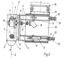
- a body casing 10 which is adjusted around the jaws is shown in the figure 2 from which body casing the device can be attached in a such known way for example to an excavator through a tilting mechanism 15, 16 and a possible rotating device. Structures have been directed from the body casing 10 inwards in order to attach joint pins 11 to a casing 10 and in order to attach a hydraulic motor 8 to the casing 10. Also the other end of the cylinder is attached to the body casing 10. The backmost jaw arms 7 of the pair of jaws, gripping heads 2 and the attachment line L of the object are shown in the figure 2 .
- the hydraulic motor 8 rotates through an articulated shaft 11 the upper eccentric axis 19 of both vibrator devices ( figures 4 and 5 ).
- a diverging rotating movement is arranged for them at their own articulated shafts, but as a mirror image at the same stage, such as is shown more accurately in the figures 4 and 5 .
- FIG 3 a body casing 10 and two support plates 21 which are adjusted inside it are shown in the figure 3 which body casing and support plates can be used as aids when one attaches for example joint pins 11, the hydraulic motor 8 and a cylinder 9 to the body casing 10.
- the figures 4 and 5 show how two vibrator devices with two axes can be used as vibrator devices 1 the rotating directions of the axes 19 of which vibrator devices are reversed both in relation to the axes 19 of the adjacent vibrator device and in the separate vibrator device.
- the eccentric masses 20 of the adjacent vibrator devices are located symmetrically in relation to the vertical centre line.
- the adjacent vibrator devices are almost like the same device regarding their body.
- sideway impacts do not occur in this kind of solution. Only two rotating eccentric masses 20 are needed at the ends of both jaw arms 7 in order to create impacts. Sideway forces are being compensated when the jaw arms 7 are being compressed against each other.
Landscapes
- Engineering & Computer Science (AREA)
- Mechanical Engineering (AREA)
- Life Sciences & Earth Sciences (AREA)
- General Life Sciences & Earth Sciences (AREA)
- Mining & Mineral Resources (AREA)
- Paleontology (AREA)
- Civil Engineering (AREA)
- General Engineering & Computer Science (AREA)
- Structural Engineering (AREA)
- Apparatuses For Generation Of Mechanical Vibrations (AREA)
- Placing Or Removing Of Piles Or Sheet Piles, Or Accessories Thereof (AREA)
Claims (6)
- Hammervorrichtung zum Hämmern von Pfosten, Profilen und anderen länglichen Gegenständen in den Boden, wobei die Hammervorrichtung einen Körper (10), der an einer Arbeitsmaschine befestigt werden kann, ein oder mehrere bewegbare Paare von Klauen, die am Körper (10) befestigt sind, um den zu hämmernden Gegenstand mindestens mit einem Seitengriff zu greifen, umfasst, wobei die Klauen (7, 2) des Paares von Klauen mittels einer Regeleinheit, wie etwa einem Hydraulikzylinder (9), einander angenähert oder weiter voneinander getrennt werden können und der zu hämmernde Gegenstand zwischen den genannten Klauen (7, 2) gepresst werden kann und wobei die Vorrichtung ferner mindestens zwei Vibratorvorrichtungen (1) umfasst, um Stöße zu erzeugen, die auf beide zu hämmernde Gegenstände gerichtet werden können, und dass beide Klauen (7, 2) des Paares von Klauen ihre eigene Vibratorvorrichtung (1) umfassen, wobei die Drehungen der Vibratorvorrichtung miteinander synchronisiert sind, dadurch gekennzeichnet, dass beide Klauen einen Klauenarm (7) und an dessen Ende befestigt einen Greifkopf (2), der an dem Ende des Klauenarms (7) mittels einer Gleitschiene (5) oder mittels eines Lagers mit einer Linearrichtung befestigt ist, umfassen, wobei sich die Vibratorvorrichtungen (1) an den genannten Greifköpfen (2) befinden.
- Hammervorrichtung nach Anspruch 1, dadurch gekennzeichnet, dass die Gleitschiene (5) oder das Lager dieselbe Richtung aufweist wie die Stöße der Vibratorvorrichtung (1) .
- Hammervorrichtung nach Anspruch 1, dadurch gekennzeichnet, dass in Kombination mit den Gleitschienen (5) oder dem Lager Dämpfungsgummis (6) vorgesehen sind, wobei die Dämpfungsgummis die Greifköpfe (2) an den Klauenarmen (7) befestigen und eine wechselseitige begrenzte Vibrationsbewegung für dieselben erlauben.
- Hammervorrichtung nach Anspruch 1, dadurch gekennzeichnet, dass Drehungen mithilfe von Gelenkwellen (11) von einem Antriebsmotor (8) zu den Vibratorvorrichtungen (1) des Paares von Klauen angeordnet sind und die Drehungen auf dieselbe Stufe wie ein Spiegelbild synchronisiert sind.
- Hammervorrichtung nach Anspruch 1, dadurch gekennzeichnet, dass die Bewegung der Klauen (7, 2) des Paares von Klauen derart eingestellt ist, dass sie mittels Kniegelenkarmen (12) erfolgt, wobei das gemeinsame Kniegelenk (17) der Arme der Kniegelenkarme eingestellt ist, um mittels eines Hydraulikzylinders (9) bewegbar zu sein.
- Hammervorrichtung nach Anspruch 1, dadurch gekennzeichnet, dass die Vibratovorrichtungen (1) Seite an Seite funktionieren und an den Greifköpfen (2) beider Klauenarme (7) separat eingestellt werden, wobei diese Vibratorvorrichtungen (1) jeweils zwei Achsen (19) mit exzentrischen Massen (20) umfassen, wobei, wenn sich die Massen drehen und wenn die Greifköpfe (2) der Klauen gegeneinander gepresst sind, der Wirkeffekt einer Vibratorvorrichtung mit vier Achsen mit exzentrischen Massen mittels der zwei Vibratorvorrichtungen erreicht werden kann, die in dieser Weise installiert sind, derart, dass während des Betriebs kaum Seitenstöße bewirkt werden.
Applications Claiming Priority (2)
| Application Number | Priority Date | Filing Date | Title |
|---|---|---|---|
| FI20120071 | 2012-03-07 | ||
| PCT/FI2013/000010 WO2013132138A1 (en) | 2012-03-07 | 2013-03-05 | Hammering device meant for hammering poles and other longish objects into the ground |
Publications (4)
| Publication Number | Publication Date |
|---|---|
| EP2864549A1 EP2864549A1 (de) | 2015-04-29 |
| EP2864549A4 EP2864549A4 (de) | 2016-12-14 |
| EP2864549C0 EP2864549C0 (de) | 2023-11-08 |
| EP2864549B1 true EP2864549B1 (de) | 2023-11-08 |
Family
ID=49115988
Family Applications (1)
| Application Number | Title | Priority Date | Filing Date |
|---|---|---|---|
| EP13757881.1A Active EP2864549B1 (de) | 2012-03-07 | 2013-03-05 | Hammervorrichtung zum hämmern von pfosten und anderen länglichen gegenständen in den boden |
Country Status (2)
| Country | Link |
|---|---|
| EP (1) | EP2864549B1 (de) |
| WO (1) | WO2013132138A1 (de) |
Families Citing this family (4)
| Publication number | Priority date | Publication date | Assignee | Title |
|---|---|---|---|---|
| FI20140081A7 (fi) * | 2014-03-19 | 2015-09-20 | Movax Oy | Työkoneeseen liitettävä iskulaite |
| KR102640403B1 (ko) * | 2021-11-26 | 2024-02-22 | 허일도 | 사이드 그립 진동 해머 |
| GB2618092B (en) * | 2022-04-26 | 2024-12-11 | Dawson Const Plant Ltd | Side grip vibratory pile driver |
| DE102022127205A1 (de) * | 2022-10-18 | 2024-04-18 | Terra Infrastructure Gmbh | Seitengreifer zum Ergreifen und Eintreiben eines Rammgutes |
Family Cites Families (5)
| Publication number | Priority date | Publication date | Assignee | Title |
|---|---|---|---|---|
| GB2130997B (en) * | 1984-06-11 | 1985-09-18 | Joseph Samuel Neil | Vibration clamping device for use in supporting and placing sheeting when excavating |
| FI106219B (fi) | 1991-09-30 | 2000-12-15 | Raunisto Airi | Menetelmä ja laite paalujen tai vastaavien pakottamiseksi maaperään |
| JP2006169942A (ja) * | 2004-11-22 | 2006-06-29 | Chowa Kogyo Kk | 振動併用回転式杭打機および振動併用回転式杭打工法 |
| EP1983112B1 (de) | 2007-04-16 | 2010-01-13 | IHC Holland IE B.V. | Vibrationsrüttler zum Niederbringen eines Pfahls oder eines Formrohres |
| NL2002871C2 (nl) | 2009-05-12 | 2010-11-15 | Decombi B V | Trilinrichting. |
-
2013
- 2013-03-05 EP EP13757881.1A patent/EP2864549B1/de active Active
- 2013-03-05 WO PCT/FI2013/000010 patent/WO2013132138A1/en not_active Ceased
Also Published As
| Publication number | Publication date |
|---|---|
| EP2864549A1 (de) | 2015-04-29 |
| EP2864549C0 (de) | 2023-11-08 |
| WO2013132138A1 (en) | 2013-09-12 |
| EP2864549A4 (de) | 2016-12-14 |
Similar Documents
| Publication | Publication Date | Title |
|---|---|---|
| US8322643B2 (en) | Rock crusher attachment | |
| JP5580528B2 (ja) | 手持ち式工具装置 | |
| WO2013132138A1 (en) | Hammering device meant for hammering poles and other longish objects into the ground | |
| DK2912225T3 (en) | TRACK STOPPING MACHINE WITH SEPARATELY STIMULATED VIBRATING STOP HACKERS | |
| US9192962B2 (en) | Vibration exciter for generating a directed excitation vibration | |
| EP3329052B1 (de) | Greifmaschine | |
| KR20070021163A (ko) | 내구 강도, 특히 크랭크 축의 굽힘 강도 및 비틀림 강도를증가시키기 위한 방법 및 장치 | |
| WO2000077308A1 (en) | A device for driving piles | |
| FI128958B (fi) | Laitteisto paalujen ja ponttien iskemiseksi maaperään | |
| CN107849827B (zh) | 捣固设备 | |
| CN102561303A (zh) | 用于夯实底土的振动夯机 | |
| CN103835293A (zh) | 建筑构件安装的装置与方法 | |
| KR100794396B1 (ko) | 바닥재 제거장치 | |
| CN119096019A (zh) | 侧夹式振动打桩机 | |
| US6848858B1 (en) | Working machine with reduced upper mass vibrations | |
| CN113756276B (zh) | 一种地基修整用垫层夯实机 | |
| CN101869961B (zh) | 用于锻造机的操作器 | |
| FI20100158A7 (fi) | Paalujen maahan iskemiseen tarkoitettu laitteisto | |
| AU2006248194B2 (en) | Improved hammer mounting | |
| EP2660394A1 (de) | System zur zerkleinerung von steinen und dergleichen | |
| EP3119940B1 (de) | Hammervorrichtung | |
| KR101650906B1 (ko) | 단동식 저진동 과수털기 겸용 항타기 | |
| KR20100002095U (ko) | 바닥재 철거장치 | |
| KR101359024B1 (ko) | 진동 브레이커 | |
| RU2116385C1 (ru) | Устройство для разрушения корки электролита |
Legal Events
| Date | Code | Title | Description |
|---|---|---|---|
| PUAI | Public reference made under article 153(3) epc to a published international application that has entered the european phase |
Free format text: ORIGINAL CODE: 0009012 |
|
| 17P | Request for examination filed |
Effective date: 20150319 |
|
| AK | Designated contracting states |
Kind code of ref document: A1 Designated state(s): AL AT BE BG CH CY CZ DE DK EE ES FI FR GB GR HR HU IE IS IT LI LT LU LV MC MK MT NL NO PL PT RO RS SE SI SK SM TR |
|
| AX | Request for extension of the european patent |
Extension state: BA ME |
|
| DAX | Request for extension of the european patent (deleted) | ||
| RA4 | Supplementary search report drawn up and despatched (corrected) |
Effective date: 20161115 |
|
| RIC1 | Information provided on ipc code assigned before grant |
Ipc: E02D 7/18 20060101AFI20161109BHEP Ipc: E02D 11/00 20060101ALI20161109BHEP Ipc: B06B 1/16 20060101ALI20161109BHEP |
|
| STAA | Information on the status of an ep patent application or granted ep patent |
Free format text: STATUS: REQUEST FOR EXAMINATION WAS MADE |
|
| RAP1 | Party data changed (applicant data changed or rights of an application transferred) |
Owner name: Y RAUNISTO OY LTD |
|
| RIN1 | Information on inventor provided before grant (corrected) |
Inventor name: RAUNISTO, YRJOE |
|
| STAA | Information on the status of an ep patent application or granted ep patent |
Free format text: STATUS: EXAMINATION IS IN PROGRESS |
|
| 17Q | First examination report despatched |
Effective date: 20190528 |
|
| GRAP | Despatch of communication of intention to grant a patent |
Free format text: ORIGINAL CODE: EPIDOSNIGR1 |
|
| STAA | Information on the status of an ep patent application or granted ep patent |
Free format text: STATUS: GRANT OF PATENT IS INTENDED |
|
| INTG | Intention to grant announced |
Effective date: 20220729 |
|
| GRAS | Grant fee paid |
Free format text: ORIGINAL CODE: EPIDOSNIGR3 |
|
| GRAA | (expected) grant |
Free format text: ORIGINAL CODE: 0009210 |
|
| STAA | Information on the status of an ep patent application or granted ep patent |
Free format text: STATUS: THE PATENT HAS BEEN GRANTED |
|
| AK | Designated contracting states |
Kind code of ref document: B1 Designated state(s): AL AT BE BG CH CY CZ DE DK EE ES FI FR GB GR HR HU IE IS IT LI LT LU LV MC MK MT NL NO PL PT RO RS SE SI SK SM TR |
|
| REG | Reference to a national code |
Ref country code: GB Ref legal event code: FG4D |
|
| REG | Reference to a national code |
Ref country code: CH Ref legal event code: EP |
|
| REG | Reference to a national code |
Ref country code: DE Ref legal event code: R096 Ref document number: 602013084901 Country of ref document: DE |
|
| REG | Reference to a national code |
Ref country code: IE Ref legal event code: FG4D |
|
| U01 | Request for unitary effect filed |
Effective date: 20231204 |
|
| U07 | Unitary effect registered |
Designated state(s): AT BE BG DE DK EE FI FR IT LT LU LV MT NL PT SE SI Effective date: 20231208 |
|
| PG25 | Lapsed in a contracting state [announced via postgrant information from national office to epo] |
Ref country code: GR Free format text: LAPSE BECAUSE OF FAILURE TO SUBMIT A TRANSLATION OF THE DESCRIPTION OR TO PAY THE FEE WITHIN THE PRESCRIBED TIME-LIMIT Effective date: 20240209 |
|
| PG25 | Lapsed in a contracting state [announced via postgrant information from national office to epo] |
Ref country code: IS Free format text: LAPSE BECAUSE OF FAILURE TO SUBMIT A TRANSLATION OF THE DESCRIPTION OR TO PAY THE FEE WITHIN THE PRESCRIBED TIME-LIMIT Effective date: 20240308 |
|
| PG25 | Lapsed in a contracting state [announced via postgrant information from national office to epo] |
Ref country code: ES Free format text: LAPSE BECAUSE OF FAILURE TO SUBMIT A TRANSLATION OF THE DESCRIPTION OR TO PAY THE FEE WITHIN THE PRESCRIBED TIME-LIMIT Effective date: 20231108 |
|
| PG25 | Lapsed in a contracting state [announced via postgrant information from national office to epo] |
Ref country code: IS Free format text: LAPSE BECAUSE OF FAILURE TO SUBMIT A TRANSLATION OF THE DESCRIPTION OR TO PAY THE FEE WITHIN THE PRESCRIBED TIME-LIMIT Effective date: 20240308 Ref country code: GR Free format text: LAPSE BECAUSE OF FAILURE TO SUBMIT A TRANSLATION OF THE DESCRIPTION OR TO PAY THE FEE WITHIN THE PRESCRIBED TIME-LIMIT Effective date: 20240209 Ref country code: ES Free format text: LAPSE BECAUSE OF FAILURE TO SUBMIT A TRANSLATION OF THE DESCRIPTION OR TO PAY THE FEE WITHIN THE PRESCRIBED TIME-LIMIT Effective date: 20231108 |
|
| PG25 | Lapsed in a contracting state [announced via postgrant information from national office to epo] |
Ref country code: RS Free format text: LAPSE BECAUSE OF FAILURE TO SUBMIT A TRANSLATION OF THE DESCRIPTION OR TO PAY THE FEE WITHIN THE PRESCRIBED TIME-LIMIT Effective date: 20231108 Ref country code: PL Free format text: LAPSE BECAUSE OF FAILURE TO SUBMIT A TRANSLATION OF THE DESCRIPTION OR TO PAY THE FEE WITHIN THE PRESCRIBED TIME-LIMIT Effective date: 20231108 Ref country code: NO Free format text: LAPSE BECAUSE OF FAILURE TO SUBMIT A TRANSLATION OF THE DESCRIPTION OR TO PAY THE FEE WITHIN THE PRESCRIBED TIME-LIMIT Effective date: 20240208 Ref country code: HR Free format text: LAPSE BECAUSE OF FAILURE TO SUBMIT A TRANSLATION OF THE DESCRIPTION OR TO PAY THE FEE WITHIN THE PRESCRIBED TIME-LIMIT Effective date: 20231108 |
|
| PG25 | Lapsed in a contracting state [announced via postgrant information from national office to epo] |
Ref country code: CZ Free format text: LAPSE BECAUSE OF FAILURE TO SUBMIT A TRANSLATION OF THE DESCRIPTION OR TO PAY THE FEE WITHIN THE PRESCRIBED TIME-LIMIT Effective date: 20231108 |
|
| PG25 | Lapsed in a contracting state [announced via postgrant information from national office to epo] |
Ref country code: SK Free format text: LAPSE BECAUSE OF FAILURE TO SUBMIT A TRANSLATION OF THE DESCRIPTION OR TO PAY THE FEE WITHIN THE PRESCRIBED TIME-LIMIT Effective date: 20231108 |
|
| PG25 | Lapsed in a contracting state [announced via postgrant information from national office to epo] |
Ref country code: SM Free format text: LAPSE BECAUSE OF FAILURE TO SUBMIT A TRANSLATION OF THE DESCRIPTION OR TO PAY THE FEE WITHIN THE PRESCRIBED TIME-LIMIT Effective date: 20231108 Ref country code: SK Free format text: LAPSE BECAUSE OF FAILURE TO SUBMIT A TRANSLATION OF THE DESCRIPTION OR TO PAY THE FEE WITHIN THE PRESCRIBED TIME-LIMIT Effective date: 20231108 Ref country code: RO Free format text: LAPSE BECAUSE OF FAILURE TO SUBMIT A TRANSLATION OF THE DESCRIPTION OR TO PAY THE FEE WITHIN THE PRESCRIBED TIME-LIMIT Effective date: 20231108 Ref country code: CZ Free format text: LAPSE BECAUSE OF FAILURE TO SUBMIT A TRANSLATION OF THE DESCRIPTION OR TO PAY THE FEE WITHIN THE PRESCRIBED TIME-LIMIT Effective date: 20231108 |
|
| REG | Reference to a national code |
Ref country code: DE Ref legal event code: R097 Ref document number: 602013084901 Country of ref document: DE |
|
| U21 | Renewal fee for the european patent with unitary effect paid with additional fee |
Year of fee payment: 12 Effective date: 20240730 |
|
| U1N | Appointed representative for the unitary patent procedure changed after the registration of the unitary effect |
Representative=s name: WEICKMANN & WEICKMANN PARTMBB; DE |
|
| PLBE | No opposition filed within time limit |
Free format text: ORIGINAL CODE: 0009261 |
|
| STAA | Information on the status of an ep patent application or granted ep patent |
Free format text: STATUS: NO OPPOSITION FILED WITHIN TIME LIMIT |
|
| 26N | No opposition filed |
Effective date: 20240809 |
|
| PG25 | Lapsed in a contracting state [announced via postgrant information from national office to epo] |
Ref country code: MC Free format text: LAPSE BECAUSE OF FAILURE TO SUBMIT A TRANSLATION OF THE DESCRIPTION OR TO PAY THE FEE WITHIN THE PRESCRIBED TIME-LIMIT Effective date: 20231108 |
|
| PG25 | Lapsed in a contracting state [announced via postgrant information from national office to epo] |
Ref country code: MC Free format text: LAPSE BECAUSE OF FAILURE TO SUBMIT A TRANSLATION OF THE DESCRIPTION OR TO PAY THE FEE WITHIN THE PRESCRIBED TIME-LIMIT Effective date: 20231108 |
|
| PG25 | Lapsed in a contracting state [announced via postgrant information from national office to epo] |
Ref country code: IE Free format text: LAPSE BECAUSE OF NON-PAYMENT OF DUE FEES Effective date: 20240305 |
|
| PG25 | Lapsed in a contracting state [announced via postgrant information from national office to epo] |
Ref country code: IE Free format text: LAPSE BECAUSE OF NON-PAYMENT OF DUE FEES Effective date: 20240305 |
|
| U20 | Renewal fee for the european patent with unitary effect paid |
Year of fee payment: 13 Effective date: 20250225 |
|
| PGFP | Annual fee paid to national office [announced via postgrant information from national office to epo] |
Ref country code: CH Payment date: 20250401 Year of fee payment: 13 |
|
| PG25 | Lapsed in a contracting state [announced via postgrant information from national office to epo] |
Ref country code: CY Free format text: LAPSE BECAUSE OF FAILURE TO SUBMIT A TRANSLATION OF THE DESCRIPTION OR TO PAY THE FEE WITHIN THE PRESCRIBED TIME-LIMIT; INVALID AB INITIO Effective date: 20130305 |
|
| PG25 | Lapsed in a contracting state [announced via postgrant information from national office to epo] |
Ref country code: HU Free format text: LAPSE BECAUSE OF FAILURE TO SUBMIT A TRANSLATION OF THE DESCRIPTION OR TO PAY THE FEE WITHIN THE PRESCRIBED TIME-LIMIT; INVALID AB INITIO Effective date: 20130305 |
|
| PG25 | Lapsed in a contracting state [announced via postgrant information from national office to epo] |
Ref country code: TR Free format text: LAPSE BECAUSE OF FAILURE TO SUBMIT A TRANSLATION OF THE DESCRIPTION OR TO PAY THE FEE WITHIN THE PRESCRIBED TIME-LIMIT Effective date: 20231108 |
|
| REG | Reference to a national code |
Ref country code: CH Ref legal event code: U11 Free format text: ST27 STATUS EVENT CODE: U-0-0-U10-U11 (AS PROVIDED BY THE NATIONAL OFFICE) Effective date: 20260401 |
|
| U20 | Renewal fee for the european patent with unitary effect paid |
Year of fee payment: 14 Effective date: 20260226 |
|
| PGFP | Annual fee paid to national office [announced via postgrant information from national office to epo] |
Ref country code: GB Payment date: 20260324 Year of fee payment: 14 |