EP2864654B1 - Guidage linéaire comprenant au moins deux éléments profilés - Google Patents
Guidage linéaire comprenant au moins deux éléments profilés Download PDFInfo
- Publication number
- EP2864654B1 EP2864654B1 EP13731719.4A EP13731719A EP2864654B1 EP 2864654 B1 EP2864654 B1 EP 2864654B1 EP 13731719 A EP13731719 A EP 13731719A EP 2864654 B1 EP2864654 B1 EP 2864654B1
- Authority
- EP
- European Patent Office
- Prior art keywords
- profile
- linear
- extruded profile
- sliding
- linear guide
- Prior art date
- Legal status (The legal status is an assumption and is not a legal conclusion. Google has not performed a legal analysis and makes no representation as to the accuracy of the status listed.)
- Not-in-force
Links
Images


Classifications
-
- F—MECHANICAL ENGINEERING; LIGHTING; HEATING; WEAPONS; BLASTING
- F16—ENGINEERING ELEMENTS AND UNITS; GENERAL MEASURES FOR PRODUCING AND MAINTAINING EFFECTIVE FUNCTIONING OF MACHINES OR INSTALLATIONS; THERMAL INSULATION IN GENERAL
- F16C—SHAFTS; FLEXIBLE SHAFTS; ELEMENTS OR CRANKSHAFT MECHANISMS; ROTARY BODIES OTHER THAN GEARING ELEMENTS; BEARINGS
- F16C29/00—Bearings for parts moving only linearly
- F16C29/02—Sliding-contact bearings
-
- F—MECHANICAL ENGINEERING; LIGHTING; HEATING; WEAPONS; BLASTING
- F16—ENGINEERING ELEMENTS AND UNITS; GENERAL MEASURES FOR PRODUCING AND MAINTAINING EFFECTIVE FUNCTIONING OF MACHINES OR INSTALLATIONS; THERMAL INSULATION IN GENERAL
- F16C—SHAFTS; FLEXIBLE SHAFTS; ELEMENTS OR CRANKSHAFT MECHANISMS; ROTARY BODIES OTHER THAN GEARING ELEMENTS; BEARINGS
- F16C29/00—Bearings for parts moving only linearly
- F16C29/005—Guide rails or tracks for a linear bearing, i.e. adapted for movement of a carriage or bearing body there along
-
- F—MECHANICAL ENGINEERING; LIGHTING; HEATING; WEAPONS; BLASTING
- F16—ENGINEERING ELEMENTS AND UNITS; GENERAL MEASURES FOR PRODUCING AND MAINTAINING EFFECTIVE FUNCTIONING OF MACHINES OR INSTALLATIONS; THERMAL INSULATION IN GENERAL
- F16C—SHAFTS; FLEXIBLE SHAFTS; ELEMENTS OR CRANKSHAFT MECHANISMS; ROTARY BODIES OTHER THAN GEARING ELEMENTS; BEARINGS
- F16C29/00—Bearings for parts moving only linearly
- F16C29/008—Systems with a plurality of bearings, e.g. four carriages supporting a slide on two parallel rails
-
- F—MECHANICAL ENGINEERING; LIGHTING; HEATING; WEAPONS; BLASTING
- F16—ENGINEERING ELEMENTS AND UNITS; GENERAL MEASURES FOR PRODUCING AND MAINTAINING EFFECTIVE FUNCTIONING OF MACHINES OR INSTALLATIONS; THERMAL INSULATION IN GENERAL
- F16C—SHAFTS; FLEXIBLE SHAFTS; ELEMENTS OR CRANKSHAFT MECHANISMS; ROTARY BODIES OTHER THAN GEARING ELEMENTS; BEARINGS
- F16C29/00—Bearings for parts moving only linearly
- F16C29/12—Arrangements for adjusting play
Definitions
- Linear guide comprising at least two profile-members
- the invention relates to a linear guide comprising at least two profile-members, preferably at least two extruded profile-members.
- Linear guides are used, for example, in telescopic arrangements or roller guides inter alia in the field of mechanical engineering.
- Linear guides in the context of the invention comprise at least two profile-members which can carry out a predetermined relative movement relative to each other.
- a so-called inner profile-member is at least partially surrounded by a so-called outer profile-member.
- linear guiding means which limit the relative movement between the profile-members of the linear guide in such a manner that only the desired relative movement between the profile-members is permitted.
- the linear guiding means are mounted at least at two opposing profile-member sides.
- US 4,566,738 discloses a state of the art positioning apparatus in which a runner is arranged to travel backwards and forwards by way of a threaded spindle extending in the lengthwise direction of the apparatus and engaging the runner.
- the runner is slidably mounted on three guide members positioned symmetrically around the spindle and in parallel therewith.
- the guide members are part of guiding profiled members forming part of the housing of the positioning apparatus. Special slide surfaces are arranged on the guide members.
- the positioning apparatus furthermore comprises bushings mounting said runner, said bushings being movable in the transverse direction of said positioning apparatus.
- US 6,648,508 discloses a linear guide which comprises a travelling carriage having track rollers for support and for rolling along a guide rail, such track rollers, each of which roles on the guide rail, being mounted in pairs for rotation on a first support that is arranged on a first carriage plate of the travelling carriage.
- the travelling carriage comprises a further carriage plate with a second support arranged thereon, and the track rollers rotatably mounted on said second support for rolling on a further guide rail.
- One of the supports is designed as a fixed bearing, the other support being designed as a movable bearing.
- the support faces of the linear guiding means must be mechanically further processed in a complex manner since otherwise occurrences of distortion up to the level of jamming may occur.
- the linear guiding means may be underlaid with spacer disks or spacer bars, so-called shims, in order thereby to compensate for occurrences of unevenness in the profile-members.
- linear guide in an advantageous variant of the linear guide according to the invention, there is provision for all the linear guiding means to be constructed as movable bearings so that the profile-members are completely arranged in a floating manner one inside the other.
- At least one additional linear guiding means forms a fixed bearing.
- a linear guiding means is constructed as a fixed bearing, whereas a diametrically opposed linear guiding means is constructed as a movable bearing so that in this manner a defined, torsion-resistant guide is ensured, at the same time with compensation of height tolerances.
- the first linear guiding means may have at least two degrees of freedom.
- the first linear guiding means may be adjustable in an axis which extends transversely relative to the displacement direction of the profile-members relative to each other.
- the first linear guiding means may be rotatably or pivotably arranged about this axis.
- the linear guiding means each to be formed by a linear guiding rail and a complementary sliding member.
- the rail and the sliding member may be constructed, for example, as groove type profile-members, for example, as dovetail profile-members.
- the sliding member of the first linear guiding means is arranged in a floating manner.
- the sliding member of the first linear guiding means is freely displaceable transversely relative to the guiding direction of the profile-members in an axis which extends perpendicularly relative to the longitudinal extent of the complementary linear guiding rail.
- the sliding member of the first linear guiding means may be retained in a resiliently loaded manner in the direction towards the guide rail.
- the sliding member of the first linear guiding means is further supported so as to be able to be rotated about at least one axis.
- This sliding member is rotatably arranged in a ball joint.
- the linear guiding rail is connected to the inner profile-member and the sliding member is connected to the outer profile-member.
- At least one linear guiding rail preferably all the linear guiding rails, is/are securely connected to the inner profile-member.
- a complex mechanical further processing operation of the support faces of the linear guiding rails is not necessary with the construction according to the invention.
- At least one linear guiding rail is secured in a guiding groove of the inner profile-member by means of sliding blocks.
- the sliding members are advantageously arranged on the outer profile-member.
- the sliding members are each connected to the outer profile-member by means of a retention device, for example, in the form of a covering plate or a covering cap.
- At least one retention device is connected to the outer profile-member so as to be able to be moved relative to the outer profile-member.
- the sliding member of the linear guide may be securely connected to the retention device since the floating support of the sliding member is achieved in that the retention device is connected to the outer profile-member so as to be able to be moved relative to the outer profile-member.
- the retention device is advantageously secured to the outer profile-member by means of sliding bushes.
- the sliding member of the first linear guiding means is retained with a ball joint in a bearing seat which is arranged in a bearing calliper member in a floating and preferably resiliently loaded manner.
- a "spherical" bearing with a height compensation is produced. Any dimensional tolerances in the width of the linear guiding rails are compensated for by means of the spherical bearing, which permits all possible degrees of freedom of the sliding member in terms of tilting and rotation.
- a base plate to be arranged between the retention device and outer profile-member.
- the base plate may in this instance act, for example, as a support for fitting screws which are used to secure the retention device.
- fitting screws there may also be provision for the guiding and securing to be achieved by separately constructed means.
- the outer profile-member is constructed in several parts, preferably two, three or four parts.
- the multi-part construction of the outer profile-member has the advantage that, in particular with relatively large profile-member cross sections, the tool and production costs of the outer profile-member are reduced.
- the spacing of the various parts of the outer profile-member relative to each other may be ensured, for example, by means of the base plate.
- the position of the sliding member can be adjusted relative to the outer profile-member in order to center the inner profile-member in the outer profile-member.
- the position of the sliding member relative to the outer profile-member the position of the inner profile-member in the outer profile-member can be adjusted.
- Figure 1 shows a linear guide 1 comprising an inner extruded profile-member 2 and an outer extruded profile-member 3. Between the inner extruded profile-member 2 and the outer extruded profile-member 3, there are arranged at opposing sides two linear guiding means which guide a relative movement between the inner extruded profile-member 2 and the outer extruded profile-member 3.
- the linear guiding means each comprise a linear guiding rail 4 and a sliding member 5.
- the linear guiding rail 4 is arranged in a guiding groove 6 inside the inner extruded profile-member 2.
- the linear guiding rail 4 is connected to the outer extruded profile-member 3 by means of a retention device 7.
- occurrences of distortion may occur in the region of the linear guiding means during a relative movement between the inner extruded profile-member 2 and outer extruded profile-member 3.
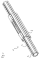
- Figure 2 shows a linear guide according to the invention comprising an inner extruded profile-member 2 and an outer extruded profile-member 3.
- the linear guide 1 comprises two linear guiding means which are arranged between the inner extruded profile-member 2 and the outer extruded profile-member 3 at opposing sides.
- the linear guiding means serve to guide the relative movement between the inner extruded profile-member 2 and the outer extruded profile-member 3.
- the linear guide 1 according to the invention differs from the prior art in that, at least at one side, at least a portion of a linear guiding means is constructed in such a manner that at least a compensation of the height tolerances is carried out at that location.
- the linear guiding means each comprise a linear guiding rail 4 and a sliding member 5.
- the linear guiding rails 4 are securely connected to the inner extruded profile-member 2.
- the linear guiding rails are retained in a guiding groove 6 of the inner extruded profile-member 2 by means of sliding blocks 8.
- the sliding members 5 are connected to the outer extruded profile-member 3 by means of a retention device 7. A floating support is thereby ensured. According to the embodiment illustrated, the sliding member 5 is securely connected to the retention device 7.
- the retention device 7 is in the form of a covering cap in this instance.
- a base plate 9 is arranged between the retention device 7 and the outer extruded profile-member 3.
- the position of the sliding member 5 relative to the outer extruded profile-member 3 is constructed so as to be adjustable in order to be able to center the inner extruded profile-member 2 in the outer extruded profile-member 3.
- the position of the sliding member 5 relative to the outer extruded profile-member 3 can be changed by means of the grub screws 10.
- the sliding member 5 illustrated at the top in the figure is constructed so as to be movable relative to the outer extruded profile-member 3, whilst the sliding member 5 illustrated in the lower region of Figure 3 is securely connected to the outer extruded profile-member 3, that is to say, forms a fixed bearing. If occurrences of distortion now occur between the inner extruded profile-member 2 and the outer extruded profile-member 3 during relative movement, they can be compensated for by means of a relative movement of the upper sliding member 5 relative to the outer extruded profile-member 3 so that jamming of the relative movement between the inner extruded profile-member 2 and outer extruded profile-member 3 is prevented.
- the relative movement between the retention device 7 and outer extruded profile-member 3 is achieved by means of fitting screws which extend through a sliding bush 11.
- a plurality of retention devices 7 with associated sliding members 5 may be arranged in the longitudinal direction of the outer extruded profile-member 3. At the upper side of the outer extruded profile-member 3, two such retention devices 7 with associated sliding members 5 are illustrated in Figure 2 .
- the outer extruded profile-member 3 has at least one recess 12 which is at least slightly larger than the external dimension of the sliding member 5.
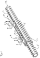
- Figure 3 is an exploded view of the linear guide 1 from Figure 2 .
- the inner extruded profile-member 2 has at opposing sides a linear guiding rail 4 which is retained in a guiding groove 6 inside the inner extruded profile-member 2 by means of sliding blocks.
- two sliding members 5 are arranged in the upper region of the outer extruded profile-member 3 in the embodiment illustrated.
- the sliding members 5 are securely connected to the retention device 7.
- the retention device 7 is connected to the outer extruded profile-member 3 by means of fitting screws with a sliding bush 11 via a base plate 9.
- the guiding of the fitting screws in the sliding bushes 11 enables a relative movement between the retention device 7 and outer extruded profile-member 3.
- the position of the sliding member 5 relative to the outer extruded profile-member 3 can be changed, whereby the inner extruded profile-member 2 can be centerd in the outer extruded profile-member 3.
- the sliding members 5 are arranged in a recess 12 within the outer extruded profile-member 3.
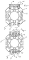
- Figure 4 is a cross section through the linear guide 1 according to Figure 2 in the region of the sliding members 5.
- the upper sliding member 5 is connected to the retention device 7 by means of a screw arrangement 13.
- the retention device 7 is connected to the outer extruded profile-member 3 by means of fitting screws with a sliding bush 11.
- a base plate 9 which is connected to the outer extruded profile-member 3 by means of sliding blocks 8.
- the lower sliding member 5 is connected to the lower retention plate 7 in Figure 4 by means of a screw arrangement 13.
- the lower retention device 7 is securely connected to the outer extruded profile-member 3 by means of sliding blocks 8.
- the sliding members 5 cooperate in each case with a linear guiding rail 4 in order to guide the relative movement between the outer extruded profile-member 3 and the inner extruded profile-member 2.
- the linear rails 4 which are arranged at opposite sides of the inner extruded profile-member 2 are securely connected to the inner extruded profile-member 2 by means of sliding blocks 8.
- the linear rails 4 are in each case arranged inside a guiding groove 6 in the inner extruded profile-member 2.
- Figure 5 is a sectioned view through the linear guide 1 according to Figure 2 in the region of the retention device 7, outside the sliding members 5.
- the retention device 7 illustrated at the top in Figure 5 is connected to the outer extruded profile-member 3 so as to be movable relative to the outer extruded profile-member 3 by means of fitting screws with a sliding bush 11.
- a base plate 9 is arranged between the retention device 7 and outer extruded profile-member 3.
- the retention device 7 in the lower region of the device according to Figure 5 is securely connected to the outer extruded profile-member 3 by means of a screw arrangement 13 and sliding blocks 8.
- Linear guiding rails 4 are connected to the inner extruded profile-member 2 at opposing sides.
- the linear guiding rails 4 are arranged between the inner extruded profile-member 2 and the outer extruded profile-member 3 in order to guide a relative movement between the inner extruded profile-member 2 and outer extruded profile-member 3.
- the linear guiding rails 4 cooperate with sliding members 5.
- the linear guiding rails are constructed as dovetail profile-members, the sliding members 5 are constructed in a complementary manner thereto and engage around them.
- the sliding member 5 which belongs to the retention device 7 in the upper region of the device according to Figure 5 is movably connected to the outer extruded profile-member 3 by means of the retention device 7, whilst the sliding member 5 which belongs to the retention device 7 in the lower region of Figure 5 is securely connected to the outer extruded profile-member.
- the upper sliding member 5 is constructed so as to be movable relative to the outer extruded profile-member 3, height tolerances of the linear rails 4 and/or the inner extruded profile-member 2 can be compensated for.
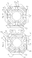
- Figure 6 shows a linear guide 1 according to the invention, three linear guiding rails 4 being securely connected to the inner extruded profile-member 2.
- the linear guiding rails 4 are each connected to the inner extruded profile-member 2 in a guiding groove 6 within the inner extruded profile-member 2.
- Sliding members 5 which are connected to the outer extruded profile-member 3 cooperate in each case with the linear guiding rails 4 in order to guide the relative movement between the inner extruded profile-member 2 and the outer extruded profile-member 3.
- the upper and the left-hand sliding member 5 is securely connected to a retention device 7, the retention device 7 being securely connected to the outer extruded profile-member 3.
- the sliding member 5 illustrated at the bottom in Figure 6 is securely connected to a retention device 7, but with the retention device 7 being connected to the outer extruded profile-member 3 so as to be able to be moved relative to the outer extruded profile-member 3 by means of fitting screws which each extend through a sliding bush 11.
- a base plate 9 is arranged between the lower retention device 7 and outer extruded profile-member 3.
- the outer extruded profile-member 3 is constructed in three parts, the individual parts of the outer extruded profile-member 3 being fixed to each other by means of the fixed retention devices 7, that is to say, in the upper and in the left-hand region of Figure 6 .
- the fixing of the individual parts of the outer extruded profile-member 3 in the lower region is achieved by means of the base plate 9 since the retention device 7 is constructed in the lower region of Figure 6 so as to be movable relative to the outer extruded profile-member 3 and consequently cannot act as a fixing means.
- the inner extruded profile-member 2 has a groove channel 14 for a toothed belt and a groove channel 15 for a measuring strip, the toothed belt which is used being able to cooperate with a drive device which brings about a relative movement between the inner extruded profile-member 2 and outer extruded profile-member 3.
- the measuring strip used in the groove channel 15 can be used in this instance to determine the relative movement between the inner extruded profile-member 2 and outer extruded profile-member 3.
- Figure 7 shows a linear guide 1 having a four-part outer extruded profile-member 3.
- the retention devices 7 illustrated at the top and on the right in Figure 7 are securely connected to the outer extruded profile-member 3, whilst the retention devices 7 illustrated on the left and at the bottom in Figure 7 are connected to the outer extruded profile-member 3 so as to be able to be moved relative to the outer extruded profile-member 3 by means of fitting screws having a sliding bush 11.
- a base plate 9 Between the movably arranged retention devices 7 and the outer extruded profile-member 3, there is arranged a base plate 9, respectively, which plates fix the position of the individual parts of the outer extruded profile-member 3 relative to each other.
- the position of the individual parts of the outer extruded profile-member 3 in the upper and right-hand region of Figure 7 is determined by means of the retention devices 7 which are securely connected to the outer extruded profile-member 3.
- a sliding member 5 is securely connected to the retention devices 7 in each case.
- the sliding members 5 each cooperate with a linear guiding rail 4, which are arranged in each case in a guiding groove 6 in the inner extruded profile-member 2 and securely connected to the inner extruded profile-member 2.
- Figure 8 shows the linear guide according to the invention.
- the linear guiding means are constructed between the outer extruded profile-member 3 and the inner extruded profile-member 2 at the side illustrated at the bottom in the figure as fixed bearings, whereas the linear guide is constructed at the diametrically opposed side of the linear guide as a movable bearing.
- the construction of the fixed bearing side, that is to say, the linear guiding means illustrated at the bottom in Figure 8 is in accordance with the embodiment illustrated in Figures 3 and 4 , the same components being given the same reference numerals.
- the movable bearing side is constructed differently in so far as the sliding member 5 which is secured to the outer extruded profile-member 3 has at that location a plurality of degrees of freedom.
- the sliding member 5 of the movable bearing side is securely provided with a ball head 16, which is retained in a bearing seat 17 which forms a ball joint with the ball head 16.
- the bearing seat 17 is formed by two mutually complementary ball plates 18a, 18b, of which the upper ball plate 18a has a dome-like recess and the lower ball plate 18b has a circular aperture with an edge which is circular-arc-like in cross section.
- the sliding member 5 of the movable bearing side may have, in place of a ball head 16, a barrel-shaped bearing pin which has a spherical or round covering face.
- a bearing pin may, for example, be displaceably guided in a cylindrical bearing bush so that any bearing seat in the context of the above description can be dispensed with.
- a resiliently loaded bearing is not necessarily required.
- the ball plates 18a, 18b are arranged in a floating manner, that is to say, transversely relative to the guiding direction of the extruded profile-members 2, 3 inside a bearing calliper member 19 and are pretensioned by means of compression springs 20 in the direction towards the linear guiding rail 4.
- the compression springs 20 are not necessarily required for the operation and in particular for tolerance compensation.
- the bearing calliper member 19 is securely screwed to the outer extruded profile-member 3.
Landscapes
- Engineering & Computer Science (AREA)
- General Engineering & Computer Science (AREA)
- Mechanical Engineering (AREA)
- Bearings For Parts Moving Linearly (AREA)
Claims (11)
- Guidage linéaire comprenant au moins un élément profilé intérieur et au moins un élément profilé extérieur, l'élément profilé extérieur (3) entourant au moins en partie l'élément profilé intérieur (2) et les éléments profilés (2, 3) étant guidés l'un dans l'autre au moyen d'au moins deux moyens de guidage linéaire disposés l'un par rapport à l'autre de manière diamétralement opposée, dans lequel au moins un tronçon du premier moyen de guidage linéaire est disposé de manière flottante, dans lequel les moyens de guidage linéaire sont respectivement formés par un rail de guidage (4) linéaire et par un élément coulissant (5) complémentaire, dans lequel l'élément coulissant (5) du premier moyen de guidage linéaire est disposé de manière flottante et l'élément coulissant (5) du premier moyen de guidage linéaire peut être déplacé librement dans des limites prédéterminées de manière transversale par rapport à la direction de guidage des éléments profilés (2, 3), caractérisé en ce que l'élément coulissant (5) du premier moyen de guidage linéaire est disposé de manière à pouvoir tourner dans une articulation à rotule.
- Guidage linéaire selon la revendication 1, caractérisé en ce qu'au moins un deuxième moyen de guidage linéaire forme un palier fixe.
- Guidage linéaire selon la revendication 1, caractérisé en ce que l'élément coulissant (5) du premier moyen de guidage linéaire est soumis à l'action d'une force élastique de manière transversale par rapport à la direction de guidage des éléments profilés (2, 3).
- Guidage linéaire selon l'une quelconque des revendications 1 à 3, caractérisé en ce qu'au moins un rail de guidage linéaire (4), de préférence tous les rails de guidage linéaire, est/sont relié/reliés de manière fixe à l'élément profilé intérieur (2).
- Guidage linéaire selon l'une quelconque des revendications 1 à 4, caractérisé en ce que le rail de guidage linéaire (4) est fixé dans une rainure de guidage (6) de l'élément profilé intérieur (2) au moyen de patins coulissants (8).
- Guidage linéaire selon l'une quelconque des revendications 1 à 5, caractérisé en ce que l'élément coulissant (5) est disposé sur l'élément profilé extérieur (3).
- Guidage linéaire selon l'une quelconque des revendications 1 à 6, caractérisé en ce que les éléments coulissants (5) sont respectivement reliés à l'élément profilé extérieur (3) au moyen d'un dispositif de retenue (7), de préférence se présentant sous la forme d'une plaque de recouvrement ou d'un capot de recouvrement.
- Guidage linéaire selon l'une quelconque des revendications 1 à 7, caractérisé en ce que l'élément profilé extérieur (3) est constitué de plusieurs parties, de préférence de deux, trois ou quatre parties.
- Guidage linéaire selon l'une quelconque des revendications 1 à 8, caractérisé en ce que la position de l'élément coulissant (5) par rapport à l'élément coulissant extérieur (3) peut être sensiblement ajustée afin de pouvoir centrer l'élément profilé intérieur (2) dans l'élément profilé extérieur (3).
- Guidage linéaire selon l'une quelconque des revendications 7 à 9, caractérisé en ce que le dispositif de retenue (7) est fixé à l'élément profilé extérieur (3) au moyen de douilles coulissantes (11).
- Guidage linéaire selon l'une quelconque des revendications 1 à 10, caractérisé en ce que l'élément coulissant (5) du premier moyen de guidage linéaire est retenu au moyen d'une articulation à rotule dans un siège de palier (17), qui est disposé dans un élément formant étrier de palier (19) de manière flottante et de préférence de manière à être soumis à l'action d'une force élastique.
Applications Claiming Priority (2)
| Application Number | Priority Date | Filing Date | Title |
|---|---|---|---|
| DE102012012530.5A DE102012012530A1 (de) | 2012-06-26 | 2012-06-26 | Linearführung aus wenigstens zwei Profilen |
| PCT/EP2013/062681 WO2014001161A1 (fr) | 2012-06-26 | 2013-06-19 | Guidage linéaire comprenant au moins deux éléments profilés |
Publications (2)
| Publication Number | Publication Date |
|---|---|
| EP2864654A1 EP2864654A1 (fr) | 2015-04-29 |
| EP2864654B1 true EP2864654B1 (fr) | 2016-07-27 |
Family
ID=48699746
Family Applications (1)
| Application Number | Title | Priority Date | Filing Date |
|---|---|---|---|
| EP13731719.4A Not-in-force EP2864654B1 (fr) | 2012-06-26 | 2013-06-19 | Guidage linéaire comprenant au moins deux éléments profilés |
Country Status (7)
| Country | Link |
|---|---|
| US (1) | US9790989B2 (fr) |
| EP (1) | EP2864654B1 (fr) |
| CN (1) | CN104471261B (fr) |
| BR (1) | BR112014032322A2 (fr) |
| DE (1) | DE102012012530A1 (fr) |
| RU (1) | RU2587738C1 (fr) |
| WO (1) | WO2014001161A1 (fr) |
Families Citing this family (3)
| Publication number | Priority date | Publication date | Assignee | Title |
|---|---|---|---|---|
| NL2018738B1 (en) * | 2017-04-19 | 2018-10-29 | Almotion B V | Guide unit and method for manufacturing such a guide unit. |
| DE202018104466U1 (de) | 2018-08-02 | 2018-09-21 | Igus Gmbh | Teleskopsystem |
| EP4689432A1 (fr) * | 2023-03-31 | 2026-02-11 | igus SE & Co. KG | Ensemble rail coulissant rinçable |
Family Cites Families (23)
| Publication number | Priority date | Publication date | Assignee | Title |
|---|---|---|---|---|
| US3398999A (en) * | 1966-08-15 | 1968-08-27 | Ex Cell O Corp | Linear motion ball bearing assembly |
| DE2607674A1 (de) * | 1975-02-28 | 1976-09-09 | Hiroshi Teramachi | Gleitbahnlagerung |
| SE439968B (sv) * | 1982-10-19 | 1985-07-08 | Ulf Kenneth Folke Fasth | Stelldon |
| US4527840A (en) * | 1983-02-10 | 1985-07-09 | Thomson Industries, Inc. | Linear bearing |
| US4637738A (en) * | 1985-07-31 | 1987-01-20 | Vincent Barkley | Alignment compensator for linear bearings |
| JPS62188636A (ja) * | 1986-02-12 | 1987-08-18 | Hiroshi Teramachi | 直線案内装置 |
| FR2604111B1 (fr) * | 1986-09-23 | 1988-12-30 | Micro Controle | Systeme de guidage lineaire a organes de roulement et dispositif de reglage pour un tel systeme |
| DE3834900A1 (de) * | 1988-10-13 | 1990-04-19 | Boening Manfred | Linearfuehrung - mit selbstnachstellender spieleinstellung ein- und mehrspurig nicht verdrehbar |
| JPH04127418U (ja) * | 1991-05-10 | 1992-11-19 | 日本トムソン株式会社 | 直動転がり案内ユニツト |
| US5388913A (en) * | 1993-04-08 | 1995-02-14 | Ohmstede-Cawley, Ltd. | Linear bearing compensation system |
| DE9315178U1 (de) * | 1993-10-07 | 1995-02-09 | Pies Gerrit | Linearführung |
| DE29613666U1 (de) * | 1996-08-07 | 1997-12-04 | Pies Gerrit | Führungsgestell |
| FR2755653B1 (fr) | 1996-11-14 | 1999-01-08 | Faure Bertrand Equipements Sa | Glissiere pour siege de vehicule, et siege equipe d'une telle glissiere |
| JP4571730B2 (ja) | 1999-07-29 | 2010-10-27 | Thk株式会社 | 相対可動装置 |
| DE19942058A1 (de) * | 1999-09-03 | 2001-03-08 | Schaeffler Waelzlager Ohg | Linearführung |
| DE20013363U1 (de) * | 2000-08-03 | 2000-12-21 | Igus Spritzgußteile für die Industrie GmbH, 51147 Köln | Loslager |
| JP3913598B2 (ja) * | 2002-04-16 | 2007-05-09 | アイダエンジニアリング株式会社 | プレス機械のスライドガイド装置 |
| JP2004232783A (ja) * | 2003-01-31 | 2004-08-19 | Toshiba Mach Co Ltd | 直線案内装置 |
| DE10342386B3 (de) * | 2003-09-13 | 2004-04-29 | Mannesmann Plastics Machinery Gmbh | Linearführung |
| DE202006013952U1 (de) * | 2006-09-12 | 2006-11-02 | Rk Rose + Krieger Gmbh Verbindungs- Und Positioniersysteme | Lineareinheit |
| JP5208621B2 (ja) * | 2008-08-26 | 2013-06-12 | Thk株式会社 | 運動案内装置 |
| JP5807385B2 (ja) * | 2011-05-24 | 2015-11-10 | 日本精工株式会社 | 直動案内装置 |
| CN202132386U (zh) * | 2011-06-30 | 2012-02-01 | 陈颖 | 一种梁式直线导轨模组 |
-
2012
- 2012-06-26 DE DE102012012530.5A patent/DE102012012530A1/de not_active Withdrawn
-
2013
- 2013-06-19 CN CN201380034081.0A patent/CN104471261B/zh not_active Expired - Fee Related
- 2013-06-19 EP EP13731719.4A patent/EP2864654B1/fr not_active Not-in-force
- 2013-06-19 RU RU2015102080/11A patent/RU2587738C1/ru not_active IP Right Cessation
- 2013-06-19 BR BR112014032322A patent/BR112014032322A2/pt not_active IP Right Cessation
- 2013-06-19 US US14/409,690 patent/US9790989B2/en not_active Expired - Fee Related
- 2013-06-19 WO PCT/EP2013/062681 patent/WO2014001161A1/fr not_active Ceased
Also Published As
| Publication number | Publication date |
|---|---|
| DE102012012530A1 (de) | 2014-01-02 |
| CN104471261B (zh) | 2017-05-17 |
| US9790989B2 (en) | 2017-10-17 |
| BR112014032322A2 (pt) | 2017-06-27 |
| CN104471261A (zh) | 2015-03-25 |
| RU2587738C1 (ru) | 2016-06-20 |
| US20150152912A1 (en) | 2015-06-04 |
| EP2864654A1 (fr) | 2015-04-29 |
| WO2014001161A1 (fr) | 2014-01-03 |
Similar Documents
| Publication | Publication Date | Title |
|---|---|---|
| US6476525B2 (en) | Linear actuator | |
| US4576421A (en) | Linear slide bearing | |
| EP2864654B1 (fr) | Guidage linéaire comprenant au moins deux éléments profilés | |
| US3389625A (en) | Device for straightening a rectilinearly displaceable tool reciprocating member of machine tools | |
| US6338573B1 (en) | Universal guide device and moving table device using same | |
| US5439294A (en) | Linear guide | |
| CN107075891A (zh) | 可调滑动翼扇的滑架 | |
| US6227708B1 (en) | Guiding frame | |
| US20120039683A1 (en) | Ram guiding apparatus of machine tool | |
| JPH0251619A (ja) | 直線摺動用ベアリング | |
| US5249867A (en) | Linear motion guide unit assembly having a misalignment absorbing mechanism | |
| US20120058872A1 (en) | Machine tool guide carriage assembly | |
| DE3629368C2 (fr) | ||
| KR102362003B1 (ko) | 운동 안내 장치 | |
| US6164828A (en) | Support for a machine tool portal driven by linear motors on both sides | |
| US4859085A (en) | Travel device for a machine tool or a transfer machine | |
| EP2584209B1 (fr) | Agencement de guidage linéaire | |
| CN104416361A (zh) | 导轨组件及导轨组件的固定方法 | |
| CN216199843U (zh) | 用于重型电动夹爪的组合式滑动装置 | |
| WO2013056728A1 (fr) | Structure de guidage linéaire | |
| WO2010083979A1 (fr) | Entraînement direct linéaire électrodynamique | |
| US5388914A (en) | Linear motion rolling guide unit | |
| US4514018A (en) | Linear slide bearing and linear slide table unit employing the same | |
| CN210161090U (zh) | 一种整体式平衡轴分装台 | |
| SE1451590A1 (sv) | Track, load carrying carriage and track system |
Legal Events
| Date | Code | Title | Description |
|---|---|---|---|
| PUAI | Public reference made under article 153(3) epc to a published international application that has entered the european phase |
Free format text: ORIGINAL CODE: 0009012 |
|
| 17P | Request for examination filed |
Effective date: 20150106 |
|
| AK | Designated contracting states |
Kind code of ref document: A1 Designated state(s): AL AT BE BG CH CY CZ DE DK EE ES FI FR GB GR HR HU IE IS IT LI LT LU LV MC MK MT NL NO PL PT RO RS SE SI SK SM TR |
|
| AX | Request for extension of the european patent |
Extension state: BA ME |
|
| DAX | Request for extension of the european patent (deleted) | ||
| GRAP | Despatch of communication of intention to grant a patent |
Free format text: ORIGINAL CODE: EPIDOSNIGR1 |
|
| RAP1 | Party data changed (applicant data changed or rights of an application transferred) |
Owner name: KONECRANES GLOBAL CORPORATION |
|
| INTG | Intention to grant announced |
Effective date: 20160202 |
|
| GRAS | Grant fee paid |
Free format text: ORIGINAL CODE: EPIDOSNIGR3 |
|
| GRAA | (expected) grant |
Free format text: ORIGINAL CODE: 0009210 |
|
| AK | Designated contracting states |
Kind code of ref document: B1 Designated state(s): AL AT BE BG CH CY CZ DE DK EE ES FI FR GB GR HR HU IE IS IT LI LT LU LV MC MK MT NL NO PL PT RO RS SE SI SK SM TR |
|
| REG | Reference to a national code |
Ref country code: GB Ref legal event code: FG4D |
|
| REG | Reference to a national code |
Ref country code: CH Ref legal event code: EP |
|
| REG | Reference to a national code |
Ref country code: AT Ref legal event code: REF Ref document number: 816065 Country of ref document: AT Kind code of ref document: T Effective date: 20160815 |
|
| REG | Reference to a national code |
Ref country code: IE Ref legal event code: FG4D |
|
| REG | Reference to a national code |
Ref country code: DE Ref legal event code: R096 Ref document number: 602013009885 Country of ref document: DE |
|
| REG | Reference to a national code |
Ref country code: LT Ref legal event code: MG4D |
|
| REG | Reference to a national code |
Ref country code: NL Ref legal event code: MP Effective date: 20160727 |
|
| REG | Reference to a national code |
Ref country code: AT Ref legal event code: MK05 Ref document number: 816065 Country of ref document: AT Kind code of ref document: T Effective date: 20160727 |
|
| PG25 | Lapsed in a contracting state [announced via postgrant information from national office to epo] |
Ref country code: FI Free format text: LAPSE BECAUSE OF FAILURE TO SUBMIT A TRANSLATION OF THE DESCRIPTION OR TO PAY THE FEE WITHIN THE PRESCRIBED TIME-LIMIT Effective date: 20160727 Ref country code: NL Free format text: LAPSE BECAUSE OF FAILURE TO SUBMIT A TRANSLATION OF THE DESCRIPTION OR TO PAY THE FEE WITHIN THE PRESCRIBED TIME-LIMIT Effective date: 20160727 Ref country code: IS Free format text: LAPSE BECAUSE OF FAILURE TO SUBMIT A TRANSLATION OF THE DESCRIPTION OR TO PAY THE FEE WITHIN THE PRESCRIBED TIME-LIMIT Effective date: 20161127 Ref country code: LT Free format text: LAPSE BECAUSE OF FAILURE TO SUBMIT A TRANSLATION OF THE DESCRIPTION OR TO PAY THE FEE WITHIN THE PRESCRIBED TIME-LIMIT Effective date: 20160727 Ref country code: HR Free format text: LAPSE BECAUSE OF FAILURE TO SUBMIT A TRANSLATION OF THE DESCRIPTION OR TO PAY THE FEE WITHIN THE PRESCRIBED TIME-LIMIT Effective date: 20160727 Ref country code: NO Free format text: LAPSE BECAUSE OF FAILURE TO SUBMIT A TRANSLATION OF THE DESCRIPTION OR TO PAY THE FEE WITHIN THE PRESCRIBED TIME-LIMIT Effective date: 20161027 Ref country code: IT Free format text: LAPSE BECAUSE OF FAILURE TO SUBMIT A TRANSLATION OF THE DESCRIPTION OR TO PAY THE FEE WITHIN THE PRESCRIBED TIME-LIMIT Effective date: 20160727 Ref country code: RS Free format text: LAPSE BECAUSE OF FAILURE TO SUBMIT A TRANSLATION OF THE DESCRIPTION OR TO PAY THE FEE WITHIN THE PRESCRIBED TIME-LIMIT Effective date: 20160727 |
|
| PG25 | Lapsed in a contracting state [announced via postgrant information from national office to epo] |
Ref country code: BE Free format text: LAPSE BECAUSE OF FAILURE TO SUBMIT A TRANSLATION OF THE DESCRIPTION OR TO PAY THE FEE WITHIN THE PRESCRIBED TIME-LIMIT Effective date: 20160727 Ref country code: GR Free format text: LAPSE BECAUSE OF FAILURE TO SUBMIT A TRANSLATION OF THE DESCRIPTION OR TO PAY THE FEE WITHIN THE PRESCRIBED TIME-LIMIT Effective date: 20161028 Ref country code: AT Free format text: LAPSE BECAUSE OF FAILURE TO SUBMIT A TRANSLATION OF THE DESCRIPTION OR TO PAY THE FEE WITHIN THE PRESCRIBED TIME-LIMIT Effective date: 20160727 Ref country code: PT Free format text: LAPSE BECAUSE OF FAILURE TO SUBMIT A TRANSLATION OF THE DESCRIPTION OR TO PAY THE FEE WITHIN THE PRESCRIBED TIME-LIMIT Effective date: 20161128 Ref country code: SE Free format text: LAPSE BECAUSE OF FAILURE TO SUBMIT A TRANSLATION OF THE DESCRIPTION OR TO PAY THE FEE WITHIN THE PRESCRIBED TIME-LIMIT Effective date: 20160727 Ref country code: PL Free format text: LAPSE BECAUSE OF FAILURE TO SUBMIT A TRANSLATION OF THE DESCRIPTION OR TO PAY THE FEE WITHIN THE PRESCRIBED TIME-LIMIT Effective date: 20160727 Ref country code: ES Free format text: LAPSE BECAUSE OF FAILURE TO SUBMIT A TRANSLATION OF THE DESCRIPTION OR TO PAY THE FEE WITHIN THE PRESCRIBED TIME-LIMIT Effective date: 20160727 Ref country code: LV Free format text: LAPSE BECAUSE OF FAILURE TO SUBMIT A TRANSLATION OF THE DESCRIPTION OR TO PAY THE FEE WITHIN THE PRESCRIBED TIME-LIMIT Effective date: 20160727 |
|
| PG25 | Lapsed in a contracting state [announced via postgrant information from national office to epo] |
Ref country code: EE Free format text: LAPSE BECAUSE OF FAILURE TO SUBMIT A TRANSLATION OF THE DESCRIPTION OR TO PAY THE FEE WITHIN THE PRESCRIBED TIME-LIMIT Effective date: 20160727 Ref country code: RO Free format text: LAPSE BECAUSE OF FAILURE TO SUBMIT A TRANSLATION OF THE DESCRIPTION OR TO PAY THE FEE WITHIN THE PRESCRIBED TIME-LIMIT Effective date: 20160727 |
|
| REG | Reference to a national code |
Ref country code: DE Ref legal event code: R097 Ref document number: 602013009885 Country of ref document: DE |
|
| PG25 | Lapsed in a contracting state [announced via postgrant information from national office to epo] |
Ref country code: BG Free format text: LAPSE BECAUSE OF FAILURE TO SUBMIT A TRANSLATION OF THE DESCRIPTION OR TO PAY THE FEE WITHIN THE PRESCRIBED TIME-LIMIT Effective date: 20161027 Ref country code: DK Free format text: LAPSE BECAUSE OF FAILURE TO SUBMIT A TRANSLATION OF THE DESCRIPTION OR TO PAY THE FEE WITHIN THE PRESCRIBED TIME-LIMIT Effective date: 20160727 Ref country code: CZ Free format text: LAPSE BECAUSE OF FAILURE TO SUBMIT A TRANSLATION OF THE DESCRIPTION OR TO PAY THE FEE WITHIN THE PRESCRIBED TIME-LIMIT Effective date: 20160727 Ref country code: SK Free format text: LAPSE BECAUSE OF FAILURE TO SUBMIT A TRANSLATION OF THE DESCRIPTION OR TO PAY THE FEE WITHIN THE PRESCRIBED TIME-LIMIT Effective date: 20160727 Ref country code: SM Free format text: LAPSE BECAUSE OF FAILURE TO SUBMIT A TRANSLATION OF THE DESCRIPTION OR TO PAY THE FEE WITHIN THE PRESCRIBED TIME-LIMIT Effective date: 20160727 |
|
| PLBE | No opposition filed within time limit |
Free format text: ORIGINAL CODE: 0009261 |
|
| STAA | Information on the status of an ep patent application or granted ep patent |
Free format text: STATUS: NO OPPOSITION FILED WITHIN TIME LIMIT |
|
| REG | Reference to a national code |
Ref country code: FR Ref legal event code: PLFP Year of fee payment: 5 |
|
| 26N | No opposition filed |
Effective date: 20170502 |
|
| PG25 | Lapsed in a contracting state [announced via postgrant information from national office to epo] |
Ref country code: SI Free format text: LAPSE BECAUSE OF FAILURE TO SUBMIT A TRANSLATION OF THE DESCRIPTION OR TO PAY THE FEE WITHIN THE PRESCRIBED TIME-LIMIT Effective date: 20160727 |
|
| REG | Reference to a national code |
Ref country code: DE Ref legal event code: R119 Ref document number: 602013009885 Country of ref document: DE |
|
| PG25 | Lapsed in a contracting state [announced via postgrant information from national office to epo] |
Ref country code: MC Free format text: LAPSE BECAUSE OF FAILURE TO SUBMIT A TRANSLATION OF THE DESCRIPTION OR TO PAY THE FEE WITHIN THE PRESCRIBED TIME-LIMIT Effective date: 20160727 |
|
| REG | Reference to a national code |
Ref country code: CH Ref legal event code: PL |
|
| REG | Reference to a national code |
Ref country code: IE Ref legal event code: MM4A |
|
| PG25 | Lapsed in a contracting state [announced via postgrant information from national office to epo] |
Ref country code: LI Free format text: LAPSE BECAUSE OF NON-PAYMENT OF DUE FEES Effective date: 20170630 Ref country code: CH Free format text: LAPSE BECAUSE OF NON-PAYMENT OF DUE FEES Effective date: 20170630 Ref country code: LU Free format text: LAPSE BECAUSE OF NON-PAYMENT OF DUE FEES Effective date: 20170619 Ref country code: IE Free format text: LAPSE BECAUSE OF NON-PAYMENT OF DUE FEES Effective date: 20170619 Ref country code: DE Free format text: LAPSE BECAUSE OF NON-PAYMENT OF DUE FEES Effective date: 20180103 |
|
| REG | Reference to a national code |
Ref country code: FR Ref legal event code: PLFP Year of fee payment: 6 |
|
| PGFP | Annual fee paid to national office [announced via postgrant information from national office to epo] |
Ref country code: FR Payment date: 20180615 Year of fee payment: 6 |
|
| PG25 | Lapsed in a contracting state [announced via postgrant information from national office to epo] |
Ref country code: MT Free format text: LAPSE BECAUSE OF NON-PAYMENT OF DUE FEES Effective date: 20170619 |
|
| PG25 | Lapsed in a contracting state [announced via postgrant information from national office to epo] |
Ref country code: AL Free format text: LAPSE BECAUSE OF FAILURE TO SUBMIT A TRANSLATION OF THE DESCRIPTION OR TO PAY THE FEE WITHIN THE PRESCRIBED TIME-LIMIT Effective date: 20160727 |
|
| PGFP | Annual fee paid to national office [announced via postgrant information from national office to epo] |
Ref country code: GB Payment date: 20180618 Year of fee payment: 6 |
|
| PG25 | Lapsed in a contracting state [announced via postgrant information from national office to epo] |
Ref country code: HU Free format text: LAPSE BECAUSE OF FAILURE TO SUBMIT A TRANSLATION OF THE DESCRIPTION OR TO PAY THE FEE WITHIN THE PRESCRIBED TIME-LIMIT; INVALID AB INITIO Effective date: 20130619 |
|
| PG25 | Lapsed in a contracting state [announced via postgrant information from national office to epo] |
Ref country code: CY Free format text: LAPSE BECAUSE OF FAILURE TO SUBMIT A TRANSLATION OF THE DESCRIPTION OR TO PAY THE FEE WITHIN THE PRESCRIBED TIME-LIMIT Effective date: 20160727 |
|
| PG25 | Lapsed in a contracting state [announced via postgrant information from national office to epo] |
Ref country code: MK Free format text: LAPSE BECAUSE OF FAILURE TO SUBMIT A TRANSLATION OF THE DESCRIPTION OR TO PAY THE FEE WITHIN THE PRESCRIBED TIME-LIMIT Effective date: 20160727 |
|
| GBPC | Gb: european patent ceased through non-payment of renewal fee |
Effective date: 20190619 |
|
| PG25 | Lapsed in a contracting state [announced via postgrant information from national office to epo] |
Ref country code: TR Free format text: LAPSE BECAUSE OF FAILURE TO SUBMIT A TRANSLATION OF THE DESCRIPTION OR TO PAY THE FEE WITHIN THE PRESCRIBED TIME-LIMIT Effective date: 20160727 |
|
| PG25 | Lapsed in a contracting state [announced via postgrant information from national office to epo] |
Ref country code: GB Free format text: LAPSE BECAUSE OF NON-PAYMENT OF DUE FEES Effective date: 20190619 |
|
| PG25 | Lapsed in a contracting state [announced via postgrant information from national office to epo] |
Ref country code: FR Free format text: LAPSE BECAUSE OF NON-PAYMENT OF DUE FEES Effective date: 20190630 |